

Page 1

CEM3
®
User Manual
Version 1.5.1
Copyright © 2014 Electronic Theatre Controls, Inc.
All Rights reserved.
Product information and specifications subject to change.
Part Number:
7140M1200-1.5.1
Released: 2014-06
Rev A
Page 2

ETC® and Sensor® are either registered trademarks or trademarks of Electronic Theatre Controls, Inc. in the
United States and other countries.
All other trademarks, both marked and not marked, are the property of their respective owners.
ETC intends this document, whether printed or electronic, to be provided in its entirety.
Page 3

Table of Contents
Introduction . . . . . . . . . . . . . . . . . . . . . . . . . . 1
Using this Manual. . . . . . . . . . . . . . . . . . . . . . . . . . . . . . . . . . . . . . . .2
Text Conventions. . . . . . . . . . . . . . . . . . . . . . . . . . . . . . . . . . . . .2
Help from ETC Technical Services . . . . . . . . . . . . . . . . . . . . . . . . . .3
Chapter 1
Chapter 2
Getting Started . . . . . . . . . . . . . . . . . . . . . . .5
The User Interface . . . . . . . . . . . . . . . . . . . . . . . . . . . . . . . . . . . . . . .6
CEM3 face panel . . . . . . . . . . . . . . . . . . . . . . . . . . . . . . . . . . . . .6
Navigation . . . . . . . . . . . . . . . . . . . . . . . . . . . . . . . . . . . . . . . . . .6
Performing a Quick Setup . . . . . . . . . . . . . . . . . . . . . . . . . . . . . . . . .7
Other Setup Functions. . . . . . . . . . . . . . . . . . . . . . . . . . . . . . . . .8
System Reference . . . . . . . . . . . . . . . . . . . . 9
Important Concepts . . . . . . . . . . . . . . . . . . . . . . . . . . . . . . . . . . . . .10
Advanced Features (AF) . . . . . . . . . . . . . . . . . . . . . . . . . . . . . .10
Balanced (rack numbering) . . . . . . . . . . . . . . . . . . . . . . . . . . . .10
Circuit. . . . . . . . . . . . . . . . . . . . . . . . . . . . . . . . . . . . . . . . . . . . .11
Configuration . . . . . . . . . . . . . . . . . . . . . . . . . . . . . . . . . . . . . . .11
Dimmer Doubling (UL/ 120V 60 Hz systems only) . . . . . . . . . .11
Latch-Lock . . . . . . . . . . . . . . . . . . . . . . . . . . . . . . . . . . . . . . . . .12
Lug. . . . . . . . . . . . . . . . . . . . . . . . . . . . . . . . . . . . . . . . . . . . . . .12
Panic . . . . . . . . . . . . . . . . . . . . . . . . . . . . . . . . . . . . . . . . . . . . .12
Patch . . . . . . . . . . . . . . . . . . . . . . . . . . . . . . . . . . . . . . . . . . . . .13
Preset Functions . . . . . . . . . . . . . . . . . . . . . . . . . . . . . . . . . . . .13
Redundant Tracking (ESR and FDX racks only) . . . . . . . . . . . .15
Straight (rack numbering) . . . . . . . . . . . . . . . . . . . . . . . . . . . . .16
Menu Structure. . . . . . . . . . . . . . . . . . . . . . . . . . . . . . . . . . . . . . . . .17
Test . . . . . . . . . . . . . . . . . . . . . . . . . . . . . . . . . . . . . . . . . . . . . .17
About . . . . . . . . . . . . . . . . . . . . . . . . . . . . . . . . . . . . . . . . . . . . .17
Setup . . . . . . . . . . . . . . . . . . . . . . . . . . . . . . . . . . . . . . . . . . . . .18
Dimmer Property Definitions . . . . . . . . . . . . . . . . . . . . . . . . . . . . . .19
Rack Property Definitions . . . . . . . . . . . . . . . . . . . . . . . . . . . . . . . . .22
Dimmer Curves . . . . . . . . . . . . . . . . . . . . . . . . . . . . . . . . . . . . . . . .23
Linear. . . . . . . . . . . . . . . . . . . . . . . . . . . . . . . . . . . . . . . . . . . . .23
Modified Linear (Mod-Linear). . . . . . . . . . . . . . . . . . . . . . . . . . .25
Square Law (Square). . . . . . . . . . . . . . . . . . . . . . . . . . . . . . . . .25
Modified Square Law (Mod-Square) . . . . . . . . . . . . . . . . . . . . .26
Sensor 2.0 . . . . . . . . . . . . . . . . . . . . . . . . . . . . . . . . . . . . . . . . .26
Stage 1 . . . . . . . . . . . . . . . . . . . . . . . . . . . . . . . . . . . . . . . . . . .27
Stage 2 . . . . . . . . . . . . . . . . . . . . . . . . . . . . . . . . . . . . . . . . . . .27
Fluor 1 . . . . . . . . . . . . . . . . . . . . . . . . . . . . . . . . . . . . . . . . . . . .28
Fluor 2 . . . . . . . . . . . . . . . . . . . . . . . . . . . . . . . . . . . . . . . . . . . .28
Andi . . . . . . . . . . . . . . . . . . . . . . . . . . . . . . . . . . . . . . . . . . . . . .29
Table of Contents i
Page 4

VIP 90 . . . . . . . . . . . . . . . . . . . . . . . . . . . . . . . . . . . . . . . . . . . .29
Dimmer Output Diagram . . . . . . . . . . . . . . . . . . . . . . . . . . . . . . . . .30
Chapter 3
Common Tasks. . . . . . . . . . . . . . . . . . . . . .31
Recording and Playing Back Presets . . . . . . . . . . . . . . . . . . . . . . . .32
Preset Menu . . . . . . . . . . . . . . . . . . . . . . . . . . . . . . . . . . . . . . .32
Saving or Uploading Files and Firmware . . . . . . . . . . . . . . . . . . . . .33
Saving Configurations . . . . . . . . . . . . . . . . . . . . . . . . . . . . . . . .33
Loading Configurations . . . . . . . . . . . . . . . . . . . . . . . . . . . . . . .33
Loading CEM3 Software . . . . . . . . . . . . . . . . . . . . . . . . . . . . . .34
Setting Up Panic. . . . . . . . . . . . . . . . . . . . . . . . . . . . . . . . . . . . . . . .35
Setting Up Patch . . . . . . . . . . . . . . . . . . . . . . . . . . . . . . . . . . . . . . .37
Automatic Patch. . . . . . . . . . . . . . . . . . . . . . . . . . . . . . . . . . . . .37
Manual Patch. . . . . . . . . . . . . . . . . . . . . . . . . . . . . . . . . . . . . . .38
Set Data Loss Behavior . . . . . . . . . . . . . . . . . . . . . . . . . . . . . . . . . .38
Setting Up CEM3 on the Network . . . . . . . . . . . . . . . . . . . . . . . . . .39
Network Setup for Redundant Tracking Racks . . . . . . . . . . . . .39
Working with an FTP Server . . . . . . . . . . . . . . . . . . . . . . . . . . .39
Setting Rack DIP Switches and Termination . . . . . . . . . . . . . . . . . .40
DIPswitch settings . . . . . . . . . . . . . . . . . . . . . . . . . . . . . . . . . . .40
Termination Switches . . . . . . . . . . . . . . . . . . . . . . . . . . . . . . . .41
Rack Maintenance and Cleaning . . . . . . . . . . . . . . . . . . . . . . . . . . .42
Cleaning Rack Air Filters . . . . . . . . . . . . . . . . . . . . . . . . . . . . . .42
Vacuuming Dimmer Modules. . . . . . . . . . . . . . . . . . . . . . . . . . .43
Appendix A
Appendix B
Appendix C
Replacing AF Cards . . . . . . . . . . . . . . . . . . . . . . . . . . . . . . . . . . . . .44
Restore Rack Defaults . . . . . . . . . . . . . . . . . . . . . . . . . . . . . . . . . . .45
Error Messages. . . . . . . . . . . . . . . . . . . . . . 47
Using the CEM3 Web Interface . . . . . . . . . 49
System. . . . . . . . . . . . . . . . . . . . . . . . . . . . . . . . . . . . . . . . . . . .49
Dimmers . . . . . . . . . . . . . . . . . . . . . . . . . . . . . . . . . . . . . . . . . .49
Set Levels . . . . . . . . . . . . . . . . . . . . . . . . . . . . . . . . . . . . . . . . .50
Setup . . . . . . . . . . . . . . . . . . . . . . . . . . . . . . . . . . . . . . . . . . . . .50
Files . . . . . . . . . . . . . . . . . . . . . . . . . . . . . . . . . . . . . . . . . . . . . .50
Redundant Tracking Systems. . . . . . . . . . .51
Redundant Tracking Switch. . . . . . . . . . . . . . . . . . . . . . . . . . . .51
Automatic Control . . . . . . . . . . . . . . . . . . . . . . . . . . . . . . . . . . .52
Display Status . . . . . . . . . . . . . . . . . . . . . . . . . . . . . . . . . . . . . .52
Configuration Management in Redundant Tracking Systems . .53
Firmware Upgrades in Redundant Tracking Systems . . . . . . . .53
ii CEM3 User Manual
Page 5

Appendix D
FDX 3000 Dimmer Racks . . . . . . . . . . . . . . 55
Hardware . . . . . . . . . . . . . . . . . . . . . . . . . . . . . . . . . . . . . . . . . .55
Regulatory Information . . . . . . . . . . . . . . . . . . . . . . . . . . . . . . .57
Initial Setup . . . . . . . . . . . . . . . . . . . . . . . . . . . . . . . . . . . . . . . .57
Module Types . . . . . . . . . . . . . . . . . . . . . . . . . . . . . . . . . . . . . .57
Advanced Features in FDX . . . . . . . . . . . . . . . . . . . . . . . . . . . .58
FDX2000 vs. FDX3000 Dimmer Curve Comparison . . . . . . . . .59
iii
Page 6

iv CEM3 User Manual
Page 7

Introduction
Welcome to your new CEM3 Power Control system!
This manual is designed to introduce you to the CEM3 user interface and the primary
features and functions available to you in the setup and use of your CEM3 power control
system.
For additional information you may also access our online CEM3 wiki page at http://
www.etcconnect.com/Sensor3help.This wiki is updated regularly to reflect the most current
information and may provide information on less commonly used features of your CEM3.
The introduction contains the following sections:
• Using this Manual . . . . . . . . . . . . . . . . . . . . . . . . . . . . . . . . . . .2
• Text Conventions. . . . . . . . . . . . . . . . . . . . . . . . . . . . . . . . . . . .2
• Help from ETC Technical Services. . . . . . . . . . . . . . . . . . . . . .3
Introduction 1
Page 8
Using this Manual
The following graphics and conventions are used throughout this manual to convey
important information.
Note:
CAUTION:
WARNING:
WARNING:
Notes are helpful hints and information that is supplemental to the main text.
A Caution statement indicates situations where there may be undefined or
unwanted consequences of an action, potential for data loss or an equipment
problem.
A Warning statement indicates situations where damage may occur, people
may be harmed, or there are serious or dangerous consequences of an
action.
RISK OF ELECTRIC SHOCK! This warning statement indicates situations
where there is a risk of electric shock.
Text Conventions
Many of the procedures in this manual use a combination of text conventions to identify
various types of inputs that are used to program your CEM3. Below is a list of commonly
used conventions in this manual.
Bold is used to indicate a necessary action (such as a button press or menu path)
in a procedure.
[Brackets] are used to indicate the press of a tactile button on the face of the CEM3
(such as [Setup], [Test], and [Enter]).
Italics are used to indicate a menu item listed in the display window.
Right angle bracket (>) is used to indicate a flow of button presses and menu
selection options.
When used together, this instruction: [Setup]>Panic>Record Panic Look>[Enter]
indicates you should, “Press [Setup], select Panic from the menu, select Record Panic Look
from the menu, Press [Enter].”
Advantages of Electronic Version
ETC's technical documentation is designed for printed or electronic use. However, there
are many bonuses to using the electronic (.PDF) versions of our documents. Aside from
having all of the benefits of a PDF (such as word find, bookmarks, and commenting tools)
ETC documents include the ability to click headings in the Table of Contents or Index and
jump to the desired page. Also, our cross-references (indicated in blue italics like this:
Introduction, page 1) are links that may be clicked to jump to the specific part of the manual.
And all of ETC's documents are available for free download from our website:
www.etcconnect.com
You can download a .PDF copy of this manual directly from the USB port on the CEM3. See
About CEM3, page 17.
Please email comments about this manual to: TechComm@etcconnect.com
2 CEM3 User Manual
.
Page 9

Help from ETC Technical Services
If you are having difficulties, your most convenient resources are the references given in
this user manual. To search more widely, try the ETC Web site at www.etcconnect.com
the Sensor3 Online Community Wiki at http://www.etcconnect.com/Sensor3help.
If none of these resources is sufficient, contact ETC Technical Services directly at one of
the offices identified below. Emergency service is available from all ETC offices outside of
normal business hours.
When calling for help, please have the following information handy:
• Product model and serial number (located on the bottom of the CEM3)
• Dimmer manufacturer and installation type
• Other components in your system (Unison
Americas United Kingdom
Electronic Theatre Controls Inc. Electronic Theatre Controls Ltd.
Technical Services Department Technical Services Department
3031 Pleasant View Road 26-28 Victoria Industrial Estate
Middleton, WI 53562 Victoria Road,
800-775-4382 (USA, toll-free) London W3 6UU England
+1-608 831-4116 +44 (0)20 8896 1000
service@etcconnect.com service@etceurope.com
®
, other consoles, etc.)
or
Asia Germany
Electronic Theatre Controls Asia, Ltd. Electronic Theatre Controls GmbH
Technical Services Department Technical Services Department
Room 1801, 18/F Ohmstrasse 3
Tower 1, Phase 1 Enterprise Square 83607 Holzkirchen, Germany
9 Sheung Yuet Road +49 (80 24) 47 00-0
Kowloon Bay, Kowloon, Hong Kong techserv-hoki@etcconnect.com
+852 2799 1220
service@etcasia.com
Introduction 3
Page 10

4 CEM3 User Manual
Page 11

Chapter 1
Getting Started
This chapter contains the following sections:
• The User Interface . . . . . . . . . . . . . . . . . . . . . . . . . . . . . . . . . . .6
• Navigation. . . . . . . . . . . . . . . . . . . . . . . . . . . . . . . . . . . . . . . . . .6
• Performing a Quick Setup. . . . . . . . . . . . . . . . . . . . . . . . . . . . .7
1 Getting Started 5
Page 12
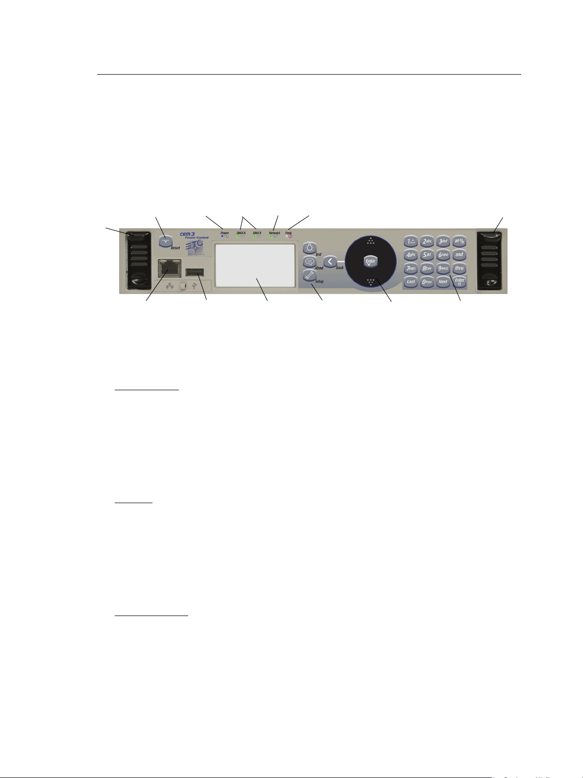
The User Interface
Eject - Pull
both levers
forward from
the top edge.
Grasp and pull
to remove
control module
(power down
the rack before
removing).
Eject
LEDs identify current states of:
Power DMX Ports Network Panic
Reset
Net3
Ethernet
USB
Load Software and
configurations
Display window Navigation
Buttons
Scroll wheel
Keypad
This section will clarify the physical features of the hardware interface and the general
functionality with the software.
CEM3 face panel
These are the various components in the hardware interface. Familiarize yourself with
these terms as they are used throughout this manual.
Navigation
Scroll Wheel
Use the scroll wheel and up/down arrows to move the selection cursor on any menu screen
until the desired item is highlighted. You can also tap the top or bottom of the scroll wheel
to move the display cursor up or down.
The scroll wheel also lets you scroll through number fields (such as circuit number) or
through the available options for a selected item (such as Module Type).
The center button of the scroll wheel functions as [Enter]. Press [Enter] to select the
highlighted item on the display window or to commit entered data.
Keypad
Use keypad to enter values for any value fields in the display window. When setting levels
you can select individual dimmers or ranges of dimmers using the [and] and [thru] buttons.
Both the center button of the scroll wheel and the bottom right keypad button function as
[Enter]. Press [Enter] to select the highlighted item on the display window or to commit
entered data.
The menu buttons ([Test], [About], [Setup]) and the [Back] button are integral in navigating
the menu structure.
Display Menus
The navigation buttons are used to navigate the menu structure.
6 CEM3 User Manual
Press the menu buttons ([Test], [About], [Setup]) to access features within that menu type
(see Menu Structure, page 17).
Use the scroll wheel to navigate through menu items in the display window, using [Enter]
to select desired items, entry fields, or access submenus.
Press [Back] to return to the previous screen on any menu.
Page 13
Performing a Quick Setup
Quick Setup is used to set up your rack using a minimum amount of data to achieve a basic
configuration.
Note:
CAUTION:
You can begin a quick setup by navigating to [Setup]>Quick Setup>[Enter].
From this interface you can use the CEM3 interface to enter data in up to four fields to
quickly establish your rack configuration: Rack Number, First Circuit, Numbering, and
Dimmer Double (see below for field descriptions).
Once you have entered data in the desired fields, select [Go] and press [Enter] to save the
setup changes.
Rack Number
Enter a reference number between 1-999 to identify the rack. Default is 1.
First Circuit
Enter the desired number for the first circuit in the rack. If this is your first or only rack, this
number is typically 1. If this rack is one of many in your system, this number typically
continues the numbering sequence from the previous rack. Default is 1.
Prior to performing a Quick Setup, make sure that your rack DIP switch settings
are set appropriately for your rack type. See Setting Rack DIP Switches and
Termination, page 40 for more information.
Quick rack setup will overwrite some of the data in your rack. Only perform a quick
setup when you wish to reconfigure your system or are instructed to do so by ETC
Technical Services.
Numbering
Choose between “Straight” or “Balanced”. “Straight” results in circuit numbering that will
proceed sequentially straight through the entire rack. See Straight (rack numbering), page
16 for more information.
“Balanced” results in circuit numbering that will distribute the circuits evenly across the
different power phases so that neighboring circuits do not place an uneven load on any
phase. See Balanced (rack numbering), page 10 for more information.
Default for Sensor3 installed racks (SR3)is “Balanced”. Default for Sensor3 portable racks
(SP3) is “Straight.”
Dimmer Double
Choose between “Yes” and “No” to activate or deactivate dimmer doubling for the rack.
Default is “No” (see Dimmer Doubling (UL/ 120V 60 Hz systems only), page 11).
1 Getting Started 7
Page 14

Other Setup Functions
Once you have completed the quick setup, you may wish to proceed to these other
common setup tasks:
Setting the module type in Circuit Assignment, page 18.
Setting Up Patch, page 37,
Setting Up Panic, page 35,
or Setting Up CEM3 on the Network, page 39.
8 CEM3 User Manual
Page 15

Chapter 2
System Reference
Refer to this chapter for information about the general concepts behind the features of your
CEM3, the general menu structure of the software, definitions of all dimmer properties, and
illustrations of the various dimmer curves available in your system.
This chapter contains the following sections:
• Important Concepts. . . . . . . . . . . . . . . . . . . . . . . . . . . . . . . . .10
• Menu Structure. . . . . . . . . . . . . . . . . . . . . . . . . . . . . . . . . . . . .17
• Dimmer Property Definitions . . . . . . . . . . . . . . . . . . . . . . . . .19
• Rack Property Definitions. . . . . . . . . . . . . . . . . . . . . . . . . . . .22
• Dimmer Curves . . . . . . . . . . . . . . . . . . . . . . . . . . . . . . . . . . . .23
• Dimmer Output Diagram . . . . . . . . . . . . . . . . . . . . . . . . . . . . .30
2 System Reference 9
Page 16

Important Concepts
This section introduces you to some of the primary concepts and their functionality, which you
may encounter through your use of the CEM3 power control system. Topics are listed
alphabetically.
Advanced Features (AF)
Advanced Features (AF) allow you to receive feedback from your dimmer modules about
their current state, including the amount of current being drawn on each circuit, whether the
module is installed or not, and whether the circuit breaker on the module has tripped. This
feedback information is available both at the front panel of the rack and at remote devices
including ETC's Eos and Congo control systems, and other ACN capable devices.
Having Advanced Features also allows you to monitor circuit loads by recording and
running a rig check (see Rig Check, page 13).
In order to use AF you need AF capable modules (denoted by having AF in the module
name, for example D20AF or ED15AF), and also AF cards installed in the rack.
Balanced (rack numbering)
Balanced rack numbering alternates dimmer numbering across phases in groups of two
dimmers.
This table compares the circuit numbering of an SR3-6 filled with D20 modules when set to
straight or balanced numbering:
SR3-6
Rack
Phase
A
B
C
Racks can be set as balanced by Performing a Quick Setup, page 7.
Straight Circuit
Numbering
11
22
37
48
53
64
79
810
95
10 6
11 11
12 12
SR3-6
Balanced Circuit
Numbering
10 CEM3 User Manual
Page 17

Circuit
A circuit is a user assignable number, between 1 and 99999. the circuit is the reference
number for that dimmer in the rack. Circuit numbers must be unique per space; it is possible
to have multiple circuits of the same number, but they must be in different spaces.
Configuration
The rack configuration is a collection of all of the data stored about the rack and all of its
circuits. The configuration is stored automatically in the CEM3 whenever you make a
change (for example, changing a circuit from switched to dimmed).
The configuration of any rack is automatically stored on both the CEM3 module and the
CEM3 backplane. Therefore, you can remove a CEM3, replace it with a new, unconfigured
CEM3, and the configuration from the backplane will be loaded to the new CEM3.
You can save and load rack configurations by connecting a USB removable media device
to the USB port on the front of the module. Saving and loading are performed from the File
Operations menu (see File Operations, page 18).
Dimmer Doubling (UL/ 120V 60 Hz systems only)
ETC’s Dimmer Doubler™ technology allows you to double the number of controllable
circuits in your system without adding dimmer modules or running additional cable. The key
to this feature is the Dimmer Doubler two-fer.
The Dimmer Doubler two-fer is installed between a Sensor dimmer module and two ETC
Source Four 77 volt fixtures. It splits the output of a single dimmer into two, separately
controlled outputs.
2 System Reference 11
Page 18
Latch-Lock
Level
Time
LatchLock On Range
LatchLock On Time
LatchLock Off Range
LatchLock Off Time
In this range the control source can go
to any level, as long as it does not stay
in the off time range for more than the
latchlock off time value
Control Level
Relay Closes
Relay Opens
Diagram of How Latch-Lock is Applied to a Circuit
Latch Lock is a control mode available to any dimmer circuit (see Control:, page 20). Similar
to switched mode, Latch-Lock features an additional safeguard so that circuits can not be
turned on or off as easily. The circuit only turns on when a defined control level range is
held for a specified amount of time, and only turns off when a different control level range
is held for another amount of time. Latch-lock is useful for avoiding accidental dowsing of
arc lamps during shows (often caused by running the Grandmaster down). By requiring a
level range and time, most master fades will not hover in a given range for long enough to
trigger on or off.
The level ranges and times can be edited on a per dimmer basis (see Dimmer Property
Definitions, page 19). On and Off level ranges may not overlap.
Lug
“Lug” refers to a physical position in the rack. Lugs are always numbered counting
downwards from the top of the rack, starting at “1.” Some modules may take up multiple lug
positions in the rack.
Panic
CEM3 offers a Panic capability that complies with UL 924 Panic functionality.
When a properly connected and enabled CEM3 has a panic “look” stored, when it receives
a signal over the panic circuit it will automatically play the recorded look.
Panic can be enabled when a maintained (normally open or normally closed) contact
closure is properly wired to the backplane (for more information, see the data termination
guide or installation guide that was supplied with the rack).
For information on how to configure Panic on your CEM3, see Setting Up Panic, page 35.
12 CEM3 User Manual
Page 19
Patch
Patching governs the relationship between control input sources (DMX A, DMX B, and
sACN) and the control of circuits in the rack. This relationship can be edited to match the
needs of your control sources and rack constraints. For information on patching, see
Setting Up Patch, page 37.
Preset Functions
CEM3 supports a built-in preset control system allowing the recording and playback of
preset looks. Preset looks can be played back either from the CEM3 face panel or using
connected Echo preset stations. For more information on recording and playing back
presets see Recording and Playing Back Presets, page 32.
CEM3 allows the circuits within the rack to be divided up into spaces (performed in Circuit
Assignment, page 18) with 64 presets available per space. Each space can only have one
active preset at a time.
CEM3 includes default presets that include all circuits in the space. The default presets for
any space start with 100% and then cycle through 75%, 50%, 25%, 100% and so on.
Sensor3’s built-in EchoConnect power supply is limited to powering six racks or panels and
six stations. An additional wall mounted or rack mounted power supply can be added to a
system to support up to sixteen hosts and sixteen stations
CAUTION:
Preset activation propagates across the Net3 network. So if a given preset is activated for
Space 1, all CEM3s on the network will activate that preset for space 1.
Rig Check
In Sensor3 racks with Advanced Features (see Advanced Features (AF), page 10) you can
record a special preset called “Rig Check” which includes both circuit levels and the amount
of load (current) expected on each circuit.
Once recorded, the rig check can be played back, either from the CEM3 face panel or
remotely, and the CEM3 will post load high, load low, or no load messages based on how
the load of the circuit has changed since you recorded the rig check preset. These
messages will be available on the CEM3 display or on a connected console that monitors
AF feedback.
Recording, running, and clearing a rig check can be performed from the Test menu (See
“Test” on page 17.)
Do not activate “Station power” on more than one CEM3 on the same
EchoConnect bus. Doing so may cause undesirable station function.
2 System Reference 13
Page 20
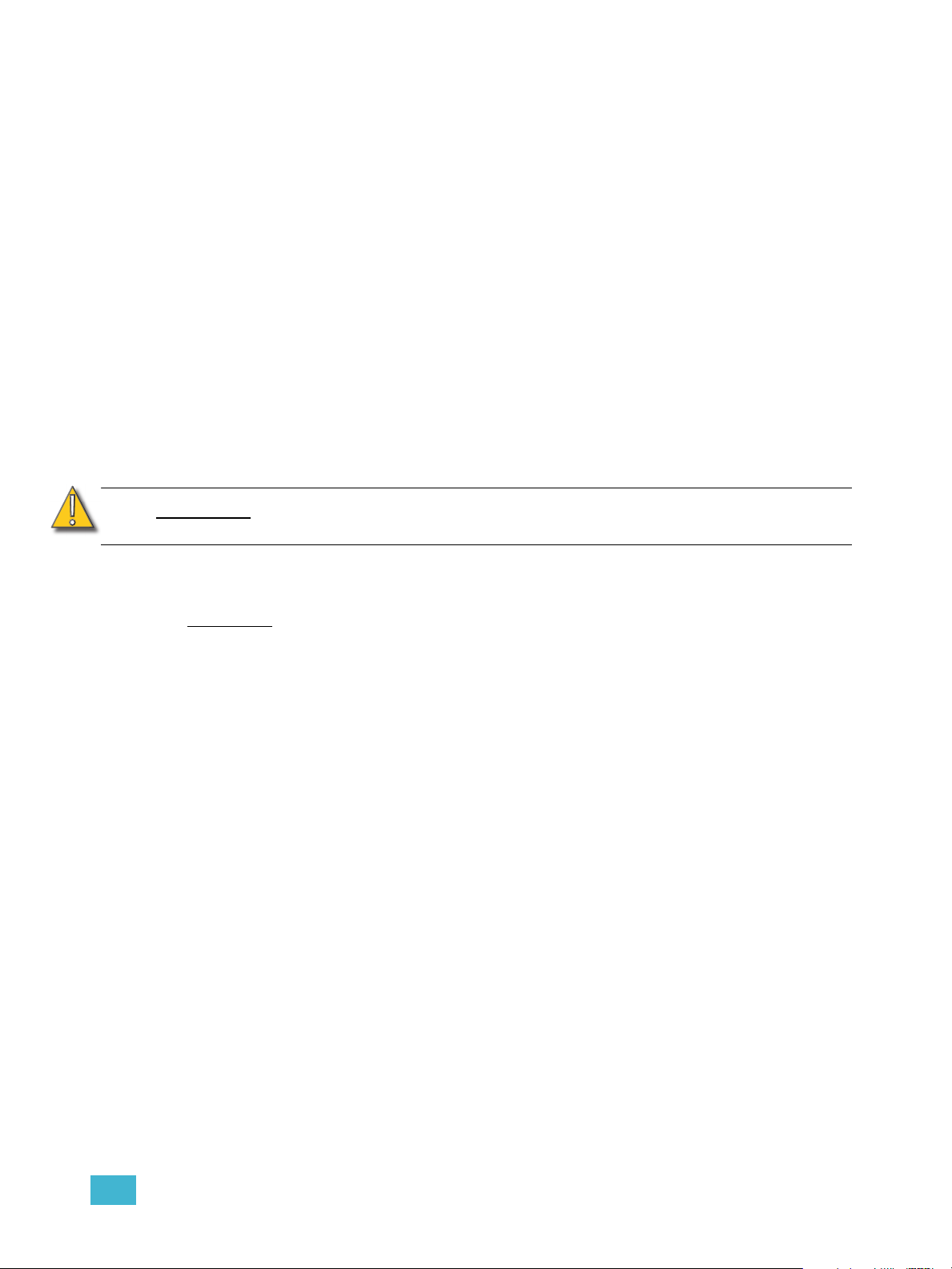
System Topology
EchoConnect - Belden 8471 + (1) 14 AWG ESD Ground Wire
External Power
Supply
Facilitates up to
16 racks and 16
stations
EchoConnect - Belden 8471 + (1) 14 AWG ESD Ground Wire
14 CEM3 User Manual
Page 21

Spaces
Spaces are logical divisions within a system (such as different rooms) that isolate station
control (preset and sequence control) to the defined group of controllable outputs in that
division. CEM3 supports separation of its controllable circuits into spaces.
Station Functions
Presets can be played back from preset stations in the system.
• Press a preset station button to activate a preset.
• Press it again to deactivate the preset.
• Stations can be configured with an “Off” button. This option is performed at the
station and should only be done by a qualified technician.
• The group of presets controlled by any station can be altered at the station. This
should only be done by a qualified technician.
For more information see the Echo Preset Station Installation Guide available from the ETC
web site.
Zones
A space can be broken down further into zones. You can assign zone control to a preset
station for direct control using that station’s buttons and fader knob. Multiple zones can exist
within a space and a single zone can control multiple outputs across multiple racks.
A circuit’s control zone is a dimmer property and is assigned by accessing the dimmer setup
menu (see “Arch Zone:” in Dimmer Property Definitions, page 19).
Each space can have up to 16 zones assigned (numbered 1-16).You can omit a circuit from
zone control by setting the Arch Zone value to zero.
Redundant Tracking (ESR and FDX racks only)
Redundant tracking provides extra security in the event of system failure, allowing a
secondary CEM3 control module to immediately take control of the rack.
Redundant tracking is available in ESR and FDX racks only.
For more information, see Redundant Tracking Systems, page 51.
2 System Reference 15
Page 22
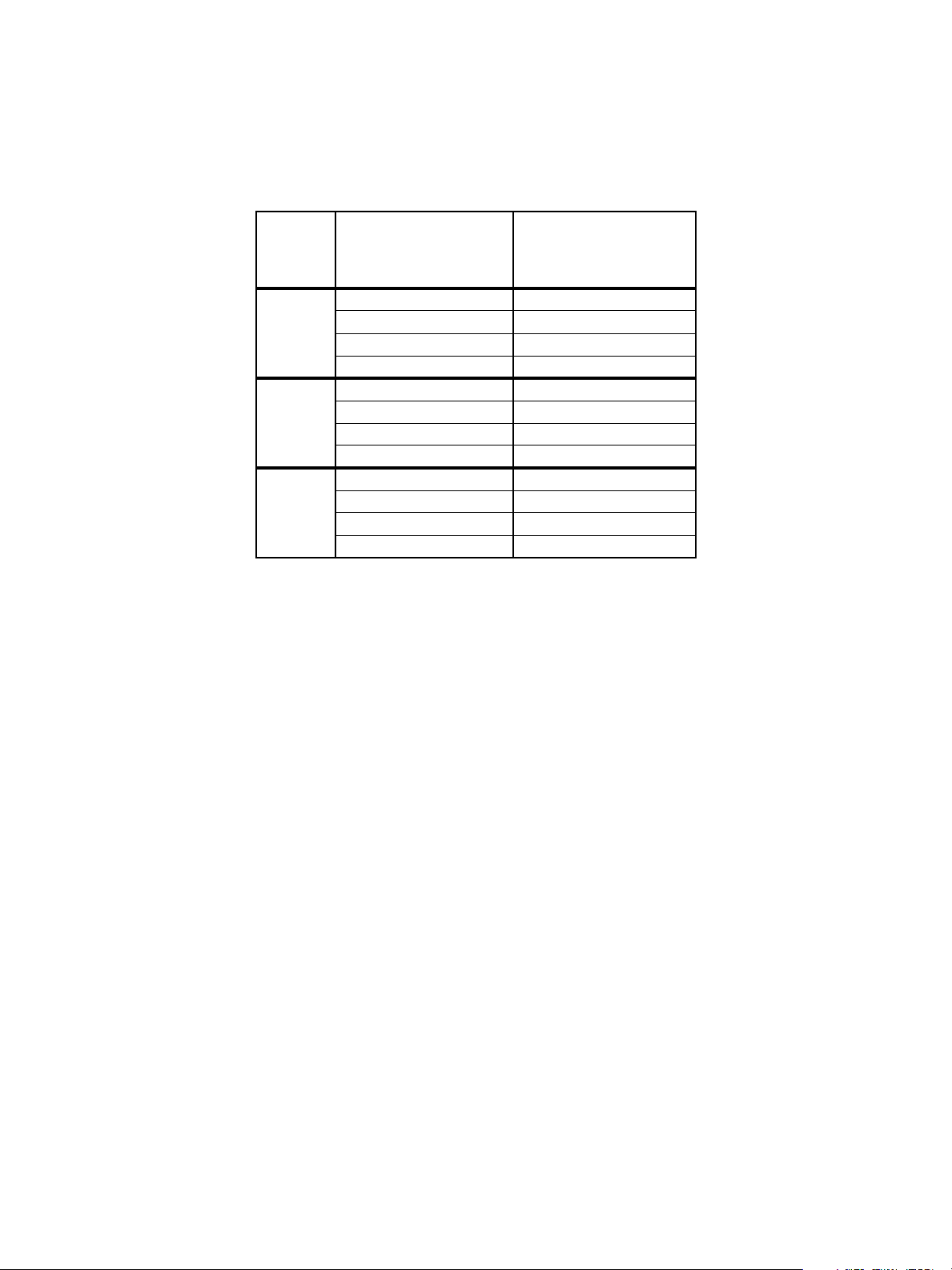
Straight (rack numbering)
Straight rack numbering assigns consecutive dimmer numbering vertically, from top of the
rack to the bottom, regardless of phasing.
This table compares the circuit numbering of an SR3-6 filled with D20 modules when set to
straight or balanced numbering:
SR3-6
Rack
Phase
A
B
C
Racks can be set to straight through Performing a Quick Setup, page 7.
Straight Circuit
Numbering
11
22
37
48
53
64
79
810
95
10 6
11 11
12 12
SR3-6
Balanced Circuit
Numbering
16 CEM3 User Manual
Page 23

Menu Structure
This section lays out the entire menu structure for the software. Press the desired button to
access the menu items below. Use the standard navigation method to select and enter
options in the menus (see Navigation, page 6).
Test
Set Levels
Set levels for all circuits in a space.
Dimmer Check
Quickly run through all circuits in a space to test their output at a given percentage.
Release Set Levels
Release any active levels for a given space at once.
Presets
Record or play back presets. See Recording and Playing Back Presets, page 32.
Record Rig Check
Records a rig check preset to facilitate AF reporting. See Rig Check, page 13 and
Advanced Features (AF), page 10 for more information.
Run Rig Check
Runs a rig check preset. You will be notified of any load inconsistencies found during the
rig check.
Clear Rig Check
Clears the recorded rig check from the CEM3.
About
Dimmers
View all properties for any circuit in a space. See Dimmer Property Definitions, page 19.
Rack
View all properties for the host Sensor rack. See Rack Property Definitions, page 22.
Errors
View any current errors or other status messages. See Error Messages, page 47.
Source Info
View the current control source (Highest-Takes-Precedence or “HTP”) and related output
level being received by all circuits in a space.
About CEM3
Download a PDF of the CEM3 User Manual to a connected USB drive.
2 System Reference 17
Page 24

Setup
Commonly used features found here include:
• changing dimmer, rack, and network settings
• enabling control ports
• changing operating mode
• upgrading software or backing up the rack configuration
• changing curve and firing mode
Dimmers
View and alter the settings for any circuit in a space. See Dimmer Property Definitions, page
19.
Rack
View and alter the settings for the host Sensor3 rack. See Rack Property Definitions, page
22.
Circuit Assignment
Assign the space, circuit number, and module type for any circuit slot in the rack. You can
auto assign or manually edit the options for any circuit.
Note:
Patching
Allows editing of the patch and functionality for any port (DMX or sACN). See Setting Up
Patch, page 37.
Network
Allows setup and editing of network properties for the CEM3. See Setting Up CEM3 on the
Network, page 39.
File Operations
Save configurations, load configurations, or upgrade CEM3 software using a USB memory
device, or you can do this from a computer on the network or FTP server. See Saving or
Uploading Files and Firmware, page 33.
Panic
Record a Panic look and set the specific details (such as fade and delay times) for when a
Panic look is executed. See Setting Up Panic, page 35.
Time/Date
Allows you to set or alter the rack’s time and date or switch between automatic or manual
time setting.
Single and half density modules such as the D20F need to be changed in the “Edit
Circuit Layout” screen of Circuit Assignment to adjust circuit numbering prior to
performing final patch updates.
Quick Setup
Allows for fast configuration of the rack. For more information see Performing a Quick
Setup, page 7.
18 CEM3 User Manual
Page 25

UI Preferences
Allows you to alter various settings regarding the user interface.
Backlight Mode
This setting affects the backlight behind the display window. Choices are “On,” “Off,”
and “Auto”. Auto will illuminate the window after a button press or boot up for the time
specified in Backlight Time. Default is “Auto.”
Backlight Time
Appears only when Backlight Mode is set to “Auto”. Specify the time in minutes and
seconds (between 0:10 and 9:59) for the backlight to stay lit after a reboot or button press.
Default is 3:00.
Contrast
Adjusts the contrast of the display window. This can also be done from the home screen by
holding the back arrow and using the scroll wheel.
Language
Alters the display language for the display window. Default is English.
Temp Locale
Alters the units used for the temperature display, Celsius (C) or Fahrenheit (F). Default is
“F”.
sACN
Determines the method of displaying sACN addresses: Universe/Channel (Uni/Ch) or
absolute address (Abs). Default is Uni/Ch.
Dimmer Property Definitions
Each dimmer has specific properties that dictate how the dimmer functions and how CEM3 will
control it. These properties are accessible and editable for any dimmer by navigating to
[Setup]>Dimmers.
Below is a list of the various dimmer properties in the order they appear on the display:
Dimmer Property Definition
Circuit Number. A user-assigned number for a unique circuit
Cct:
Lug:
Lvl:
Module:
within a “space.” Typically the circuit number matches the labelling
at the corresponding power outlet.
Describes the physical location of a circuit in a rack. This field
cannot be altered. Some module types may take up multiple lug
positions in the rack. In this case, not all module “slots” will have a
circuit number
The current level (0-100%) of the HTP source in control of the
dimmer.
The type of module controlling the circuit. Defines module density,
ratings, and features to ensure proper function of the connected
equipment and power devices in the module.
2 System Reference 19
Page 26

Dimmer Property Definition
The firing mode of the dimmer module. Options are: Normal,
Firing:
Control:
Curve:
Threshold%:
On-Level%:
Off-Level%:
On Time (sec):
Off Time (sec):
DMX A: The DMXA channel the circuit is patched to.
Dimmer Double, or Fluorescent. Specific module types will also
offer respectively: Reverse Phase, and Thru-Power.
Determines the control mode of the dimmer. Possible settings are
Dimmable, Smoothing, Off, Always-On, Switched, Latch Lock,
TPAuto, and TPDMX (see individual definitions below).
Dimmable - Circuit dims according to curve within the minimum and
maximum scaled voltages.
Smoothing - The dimmer adds a deliberately slow reaction time to
changes in control level to “smooth out” dimming performance with
loads that react quickly such as LEDs or low wattage lamps.
Off - Circuit ignores incoming levels and will not turn on even with
local overrides.
Always-On - Circuit ignores incoming levels and will not turn off even
with local overrides.
Switched - Circuit operates as a relay with output unregulated AC
voltage when the control level is above the control threshold level.
Latch-Lock - similar to switched mode, Latch-Lock functions as a
relay but features an additional safeguard so that circuits can not be
turned on or off so easily. See Latch-Lock, page 12.
TPAuto - For ThruPower modules. The control input to the circuit
dims the circuit if it is between 0 and 99%. When the output is set to
100%, the relay of the ThruPower module closes.
TPDMX - For ThruPower modules. Two addresses (or three
addresses when combined with 16-bit mode) control the dimmer and
the relay of the ThruPower module. When the second address is
below 50%, the first address acts as a relay control, turning the relay
on at the threshold value. When the second address is above 50%,
the first address acts as a dimmer in the normal manner, dimming the
output.
The current operating curve for the dimmer. Options are: Mod-
Square, Square, Linear, Mod-Linear, Sensor 2.0, and Custom 1-5.
For more information curves see Dimmer Curves, page 23.
In switched mode the threshold value defines the control
percentage at which the output turns on. In dimmed mode, the
threshold defines the level at which preheat is applied. See
Dimmer Output Diagram, page 30 for an illustration of how
threshold works with other dimmer properties.
Latch-Lock only - The control level range (as percentage) that
causes the “On Time” to start counting down. Ranges available in
10% increments. Default is 41-50%.
See Latch-Lock, page 12.
Latch-Lock only - The control level range (as percentage) that
causes the “Off Time” to start counting down. Ranges available in
10% increments. Default is 81-90%.
See Latch-Lock, page 12.
Latch-Lock only - The time that a level must be maintained before
a circuit is switched on.
seconds. See Latch-Lock, page 12.
Available range is 1-360 seconds. Default is 5
Latch-Lock only - The time that a level must be maintained before
a circuit is switched off.
seconds.See Latch-Lock, page 12.
Available range is 1-360 seconds. Default is 5
20 CEM3 User Manual
Page 27

Dimmer Property Definition
DMX A 16-Bit:
DMX B The DMXB channel the circuit is patched to.
DMX B 16-Bit:
sACN:
sACN 16-Bit:
Arch Zone:
Scale Load:
AF Enabled
Recorded Load: AF-Enabled only - Displays the recorded load for this circuit.
Actual Load: AF-Enabled only - Displays the current load for this circuit.
Min Scale (VAC):
Max Scale (VAC):
Regulation:
Preheat: Displays whether the Preheat setting is on (Yes = On).
Time (sec):
DC Out Prevent:
Inrush Protect:
Allow in Panic: Determines if this circuit should be included in the panic look.
Allow in Preset:
Determines if the circuit receives 16-Bit data from DMX A. Yes/No
(Default = No)
Determines if the circuit receives 16-Bit data from DMX B. Yes/No
(Default = No)
The sACN channel the circuit is patched to. Displayed as either
universe/channel or absolute, based on UI Preference settings
(see UI Preferences, page 19).
Determines if the circuit receives 16-Bit data from DMX A. Yes/No
(Default = No)
Set the desired zone that the circuit will control. Range is from 0-
16. Default is 1. Zero will exclude the circuit from zone control.
The scale load setting allows hyper-accurate regulation of the
voltage of the dimmer output. The scale load allows the CEM3
dimming engine to compensate for power losses occurring in the
choke of the dimmer. The scale load is calculated as the load on
the channel divided by the channel’s capacity (in Amperes) and is
expressed as a percentage. For example, a 5A load on a 20A
channel would have a scale load of 25% (5A / 20A x 100% =
25%).
Enables/disables advanced features for this circuit. Yes = AF
enabled. This field is not available for circuits set to Dimmer
Double.
Displays the minimum scale voltage of the circuit. See Dimmer
Output Diagram, page 30 for an illustration relating to this
property.
Displays the maximum scale voltage of the circuit. See Dimmer
Output Diagram, page 30 for an illustration relating to this
property.
Displays whether voltage regulation is enabled for the circuit (Yes/
No). Default is “Yes”.
Preheat Time value allows the preheat level to be sneaked back in
after a blackout to allow rapid snap blackouts. This property
specifies the length of time for the ramp back to preheat level.
Default = 2 seconds.
If enabled, ensures that both positive and negative half cycles of
the dimmer output are always equal. This setting is typically used
for loads sensitive to DC for example transformers and electronic
loads. Default is “No” (No = Off, Yes = On).
Provides a soft start feature when lamps are turned on from “0” by
ramping up the level over three mains cycles. Default is “No” (No
= Off, Yes = On).
Determines if this circuit should be included in any presets that
may be recorded in the future.
2 System Reference 21
Page 28

Dimmer Property Definition
AF-Enabled only - Defines the load reporting mode for this circuit.
Reporting Mode:
Sensitivity:
AF Reaction:
Options are: Off, No-Load, and Load Change. Default for AF
modules is Load Change.
AF-Enabled only - Defines the threshold a load can be within
before triggering a load error. Available in 0.5Amp increments. 2A
is default.
AF-Enabled only - Determines the length of time for an AF
reaction to occur. Default = 5 seconds.
Rack Property Definitions
Each rack has specific properties that dictate how the rack is identified and functions. When
selected in the Rack Setup display ([Setup]>Rack), the rack’s properties are shown on the
display window. Below is a list of the various rack properties in the order they appear on the
display:
Rack Property Definition
Rack Number:
System Number:
DMX A:
Priority (DMX A):
DMX B:
Priority (DMX B):
sACN:
Preset Priority
Fan:
AF Enabled:
Displays the current rack number, which you can change to be
between 1-999.
Displays the current system number, which you can change to be
between 1-999. Default is 1.
Toggles the output of the DMX A port between “Enabled” and
“Disabled.” When disabled the respective “Priority” field is not
visible and “Off” is displayed on the home screen. Default for DMX
A is “Enabled”.
Visible only when DMX A output is enabled. This field allows you
to configure the priority of the DMX A output signal from the rack.
Range is between 1-200 (200 = highest priority). Default is 100.
Toggles the output of the DMX B port between “Enabled” and
“Disabled.” When disabled the respective “Priority” field is not
visible and “Off” is displayed on the home screen. Default for DMX
B is “Disabled”.
Visible only when DMX B output is enabled. This field allows you
to configure the priority of the DMX B output signal from the rack.
Range is between 1-200 (200 = highest priority). Default is 100.
Toggles the output of the sACN port between “Enabled” and
“Disabled.” When disabled, “Off” displays on the home screen.
Default for sACN is “Enabled”.
Set the priority for all outgoing preset levels. Range is between
1(lowest) - 200 (Highest). Default is 100.
This is the length of time (in minutes) the rack fan will stay on after
the last load in the rack has reached 0%. Range is between 30180 minutes or can be set to “Always-on”. Default is 30.
Displays whether the rack has Advanced Features (AF) enabled
or not (Yes/No). Default is based on the backplane DIP switch
setting.
22 CEM3 User Manual
Page 29

Rack Property Definition
Presets on Boot:
Setup at Home:
Voltage High Warn:
Tem p H i g h Warn:
Station Power:
Remote Record
Data Loss Behavior:
Dimmer Curves
If enabled, and rack is rebooted when a preset (or presets) are
active, then those same presets will be reactivated when the rack
reboots.
Allows the “Quick Setup” shortcut menu option to be displayed on
the home screen. Default is “Yes” for portable racks and “No” for
install racks.
This setting defines the threshold to report an “over voltage”
condition
250VAC for 230-240VAC systems.
This setting defines the threshold to report an “over temperature”
condition
(65°C)
This setting determines whether the preset station power supply
for this CEM3 is turned on. Default is “Off” (see Preset Functions,
page 13 for more information)
This setting determines whether presets can be remotely
recorded from preset stations. Default is “No”.
Opens the “Data Loss behavior” submenu (see Set Data Loss
Behavior, page 38).
. Default is 140VAC for 100-120VAC systems and
. The range is between 32-158°F (0-70°C). Default is 149°F
Dimmer curves determine how dimmers set voltage output in response to control signal
input. To accommodate designer preferences and load response variations, Sensor3 offers
several dimmer curves which can be applied to individual dimmers (see Curve:, page 20).
The available curves in CEM3 are as follows.
Linear
The linear curve matches the control input percentage to Root Mean Squared (RMS)
voltage output. Each percent increase in control level increases dimmer voltage output by
2 System Reference 23
Page 30

the same amount.
0 20406080100
0
20
40
60
80
100
Control Input (%)
Dimmer Output (%)
24 CEM3 User Manual
Page 31

Modified Linear (Mod-Linear)
0 20406080100
0
20
40
60
80
100
Control Input (%)
Dimmer Output (%)
Control Input (%)
Dimmer Output (%)
A modified linear curve reduces the voltage change at low control levels for better
performance in low-wattage fixtures.
Square Law (Square)
At low control levels, much of a traditional incandescent fixture’s light output is in the
invisible infrared spectrum. This results in poor visible response to low control levels. A
square law curve applies a multiple derived from the square root of the control level (with
full output equal to 1.00) to increase voltage response at low control levels to compensate
for the infrared loss.
100
80
60
40
20
0
0 20406080100
2 System Reference 25
Page 32

Modified Square Law (Mod-Square)
Control Input (%)
Dimmer Output (%)
Control Input (%)
Dimmer Output (%)
A standard square law curve may overcompensate for infrared loss, resulting in “steppy”
response to incremental control changes at low levels. ETC’s modified square law curve
applies a second multiple to the standard square law curve for more uniform response to
control levels changes across the entire range of dimmer output.
100
80
60
40
20
0
0 20406080100
Sensor 2.0
The Sensor 2.0 curve is the previous version of ETC’s modified square law curve. It
provides backwards compatibility for shows created using earlier versions of ETC
equipment and familiar response for designers who prefer the earlier version.
100
80
60
40
20
0
0 20406080100
26 CEM3 User Manual
Page 33

Stage 1
Control Input (%)
Dimmer Output (%)
Control Input (%)
Dimmer Output (%)
This curve matches the stage curve of the Transtechnik PM90 dimming system.
100
80
60
40
20
0
Stage 2
This is a traditional German stage lighting curve.
0 20406080100
100
80
60
40
20
0
0 20406080100
2 System Reference 27
Page 34

Fluor 1
Control Input (%)
Dimmer Output (%)
Control Input (%)
Dimmer Output (%)
This curve is specifically for Nesys fluorescent devices.
100
80
60
40
20
0
Fluor 2
This curve is tuned to work with common 3-wire fluorescent ballasts.
0 20406080100
100
80
60
40
20
0
0 20406080100
28 CEM3 User Manual
Page 35

Andi
Control Input (%)
Dimmer Output (%)
Control Input (%)
Dimmer Output (%)
This curve is tuned to match the curve of Strand ANDI dimmer systems.
100
80
60
40
20
0
VIP 90
VIP90 is a curve specifically tuned to produce good dimming performance with the VIP-90
fluorescent ballast from SE Light management AG, commonly used in European theatrical
fluorescent luminaires.
0 20406080100
100
80
60
40
20
0
0 20406080100
2 System Reference 29
Page 36

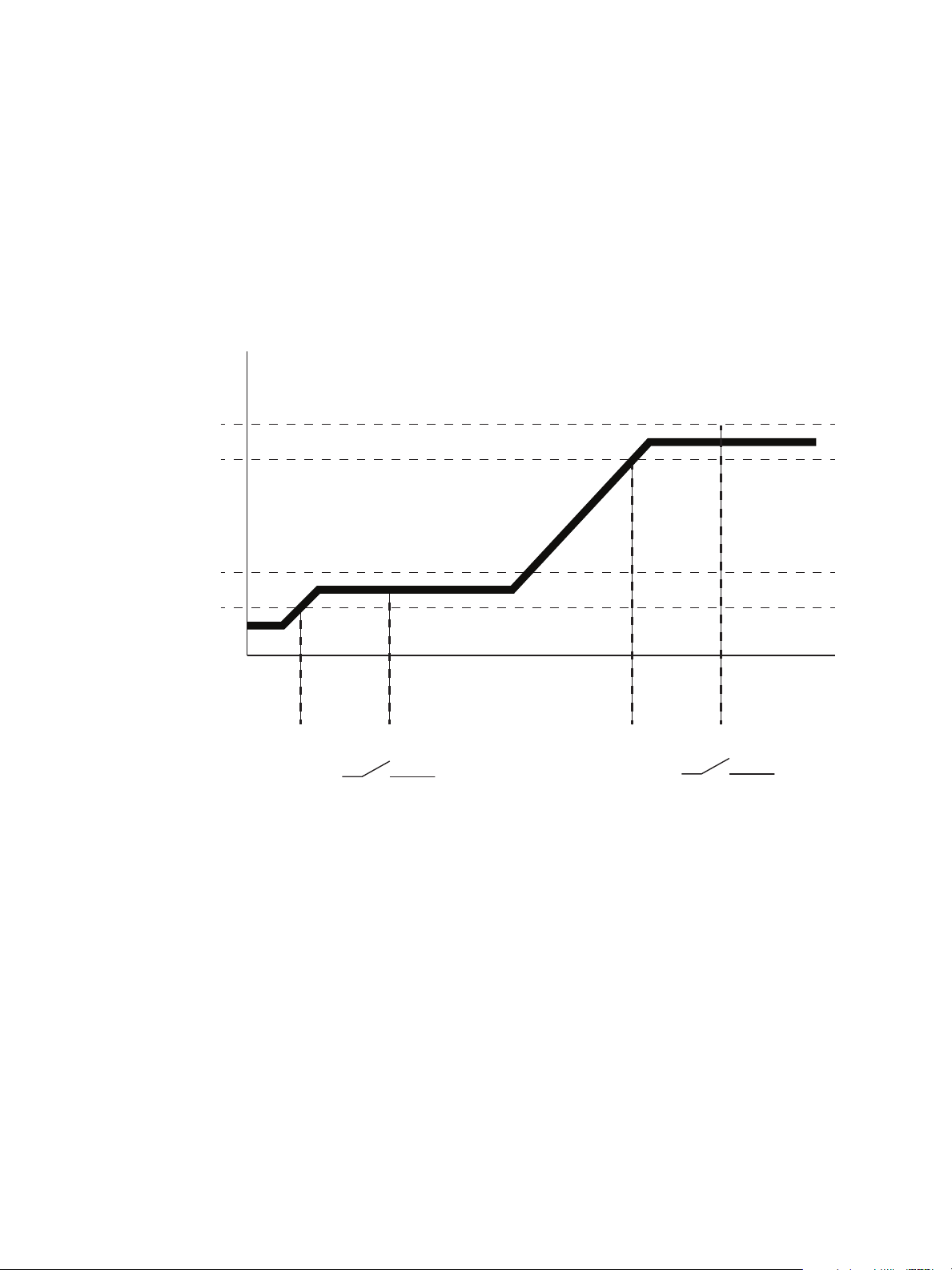
Dimmer Output Diagram
This diagram illustrates the relationship between min scale, max scale, curve, threshold,
and preheat for the dimmer output from a CEM3 channel.
Threshold(%)
Output Voltage
100%
Max Scale Voltage
Min Scale Voltage
Control Level
With Preheat Disabled
Output goes to zero
With Preheat Enabled
Output is at min scale
below threshold
30 CEM3 User Manual
Page 37

Chapter 3
Common Tasks
This chapter contains the following sections:
• Recording and Playing Back Presets . . . . . . . . . . . . . . . . . .32
• Saving or Uploading Files and Firmware . . . . . . . . . . . . . . .33
• Setting Up Panic . . . . . . . . . . . . . . . . . . . . . . . . . . . . . . . . . . .35
• Setting Up Patch . . . . . . . . . . . . . . . . . . . . . . . . . . . . . . . . . . .37
• Set Data Loss Behavior. . . . . . . . . . . . . . . . . . . . . . . . . . . . . .38
• Setting Up CEM3 on the Network. . . . . . . . . . . . . . . . . . . . . .39
• Setting Rack DIP Switches and Termination. . . . . . . . . . . . .40
• Rack Maintenance and Cleaning . . . . . . . . . . . . . . . . . . . . . .42
• Replacing AF Cards. . . . . . . . . . . . . . . . . . . . . . . . . . . . . . . . .44
3 Common Tasks 31
Page 38

Recording and Playing Back Presets
CEM3 has the ability to record and play back snapshot looks called “Presets.”
Presets can be recalled from the CEM3 or from any compatible Echo preset stations. For
information on wiring preset stations, see the Sensor3 CEM3 Data Terminations Guide and
the Echo Preset Station Installation Guide.
Up to 64 presets can be recorded for each space, numbered from 1-64. Only one preset
can be active at a time in the same space.
Preset Menu
Presets are recorded by taking a snapshot of the current levels for all circuits assigned to
the space that are set to be included in presets (see Allow in Preset:, page 21). If a circuit
is not set to be included in presets, any level it is currently using will be withheld from the
record action.
To record or play back a preset:
Step 1: Set the desired output levels for any dimmers in your rack using any method
(methods include: “Set Levels” feature on CEM3, DMX device, or sACN device).
Step 2: Using the CEM3 face panel, navigate to [Test]>Presets. The “Select Space”
screen will appear (if multiple spaces exist).
Step 3: Select the space you wish to record the preset for (if applicable) and then select
OK. The Preset screen will open.
Step 4: Select the preset (1-64) that you wish to record for the space. This will then give
you access to the preset menu. From this menu you can now perform the
following actions:
• [Activate/Deactivate] - [Enter] toggles the preset between on and off.
• [Snapshot/Record] - [Enter] records the current levels for the space to the
selected preset.
• Fade Time: set the desired time (in seconds) for the preset to fade in and out
when activated/deactivated. Range is from 0-360 seconds. Default is 2
seconds.
Step 5: Release the output levels ([Test]>Release Set Levels) or turn off the control
source data.
32 CEM3 User Manual
Page 39

Saving or Uploading Files and Firmware
CEM3 allows you to save configurations to USB removable media, a computer connected
to the network (using the CEM3 web interface), or an FTP server on the network.
You can also upload a configuration or update the CEM3 software using the same methods.
Saving Configurations
To USB media
Step 1: Navigate to [Setup]>File Operations>Save to USB. The “Save As” screen will
appear.
Step 2: If desired, edit the name of the configuration using the scroll wheel and keypad.
a: Select the file name using the scroll wheel and press [Enter]. The first
character of the rack name will be highlighted.
b: Use the keypad to alter the selected character. Keypad numbers have
standard keypad text input letters. Multiple presses of any key will cycle
through the number, lower case letters, and then upper case letters for that
key.
c: When the desired character is displayed, use the scroll wheel to move to the
next character in the rack name. If you want the name to be longer, press
[Next] to add another character.
d: Repeat steps b-c until the desired rack name is displayed.
e: When the rack name is correct, press [Enter].
Step 3: Select “OK” and press [Enter]. The configuration will be saved to the device.
To a computer
To save a configuration to a computer on the system network, see the appendix Using the
CEM3 Web Interface, page 49.
To an FTP server
To save a configuration to an FTP server on the system network, see Working with an FTP
Server, page 39.
Loading Configurations
From USB media
Step 1: Navigate to [Setup]>File Operations>Load from USB. The “Load cfg file”
screen will appear.
Step 2: Use the scroll wheel to navigate the file structure to the desired configuration file
(the file name will end in “.etc”) and press [Enter]. The configuration will load.
From a computer
To load a configuration from a computer on the system network, see the appendix Using
the CEM3 Web Interface, page 49.
To an FTP server
To load a configuration from an FTP server on the system network, see Working with an
FTP Server, page 39.
3 Common Tasks 33
Page 40

Loading CEM3 Software
You can upgrade your CEM3 software using the same methods as loading configurations
(see above). CEM3 software can be obtained by contacting ETC Technical Services (see
page 3).
From USB media
Step 1: Back up the rack configuration using the steps outlined in Saving Configurations,
page 33.
Step 2: Navigate to [Setup]>File Operations>Upgrade from USB. The “software
upgrade” screen will appear.
Step 3: Use the scroll wheel to navigate the file structure to the desired configuration file
(CEM3 software file names will end in “.bld”) and press [Enter]. A confirmation
screen will appear.
Step 4: Select “Yes” to continue. Select “No” abort the upgrade. The software upgrade
process will take several minutes.
From a computer
To load a configuration from a computer on the system network, see the appendix Using
the CEM3 Web Interface, page 49.
You can also use ETC’s Updaterator software to upgrade your CEM3. Updaterator can be
downloaded from ETC’s website www.etcconnect.com
To an FTP server
.
To load software from an FTP server on the system network, see Working with an FTP
Server, page 39.
34 CEM3 User Manual
Page 41

Setting Up Panic
To fully enable Panic functionality for your CEM3, the following criteria must be met:
• a maintained contact closure has been wired to the panic circuit on the CEM3
backplane (for more information, see the Sensor3 CEM3 Data Terminations Guide
that ships with the Sensor3 rack),
• the “Emergency Contact” switch on the CEM3 backplane is the correct position for
the contact closure type (normally open “NO” or normally closed “NC”),
• a snapshot of the desired Panic look has been recorded in the CEM3 software.
Note:
To set the Emergency Contact switch on the CEM3 backplane:
WARNING:
Step 1: Remove the CEM3 control module.
Step 2: Move the switch labeled “EMERGENCY CONTACT” to the appropriate setting:
To record a Panic look:
A Panic look can be recorded, regardless of if you have a wired Panic circuit.
Power must be turned OFF when you perform this procedure. Before
removing dimmer or control modules for service, de-energize main feed to
dimmer rack and follow appropriate Lockout/Tagout procedures as
described in NFPA Standard 70E. It is important to note that electrical
equipment such as dimmer racks can present an arc flash safety hazard if
improperly serviced. This is due to available large short circuit currents on
the feeders of the equipment. Any work on energized equipment must
comply with OSHA Electrical Safe Working Practices.
• “NC” - Use this setting if the emergency contact closure is a “Normally
Closed” contact closure.
• “Disabled” - This setting disables the Panic function for this CEM3 control
module.
• “NO” - Use this setting if the emergency contact closure is a “Normally Open”
contact closure.
Step 1: Set the desired output levels for any dimmers in your rack using any method
(methods include: Set Levels, DMX device, or sACN device).
Step 2: Using the CEM3 face panel, navigate to [Setup]>Panic>Record Panic
Look>[Enter]. If a panic look was already recorded, a confirmation screen will
appear asking you if you wish to overwrite the Panic look.
• Select “Yes/Save” to overwrite the old Panic Look. The look will be saved.
• Select “No/Cancel” to abort the record. The look will be aborted.
Once a Panic look is recorded, when the emergency contact closure is triggered the Panic
look will be activated. When the contact closure is returned to its normal state, the Panic
look will be deactivated.
Other Panic Settings
From the Panic Setup menu ([Setup]>Panic) you have access to the following settings that
will affect the manner of a Panic look activation:
• In Delay (sec) - This setting determines the length of time (in seconds) for the Panic
look to delay before activating (default is 0).
3 Common Tasks 35
Page 42

• Out Delay (sec) - This setting determines the length of time (in seconds) for the Panic
Level
Time
Panic
Activated
Panic
DeActivated
In Delay
0-360s
Fade In
0-360s
Out Delay
0-360s
Fade Out
0-360s
Steady State
until contact changes
Indicator turns on
Indicator turns off
Panic Levels
Off
Panic Fade Diagram
look to delay before deactivating (default is 0).
• Fade In (sec) - This setting determines the length of time (in seconds) for the Panic look
to fade in when activated (default is 2).
• Fade Out (sec) - This setting determines the length of time (in seconds) for the Panic
look to fade out when deactivated (default is 2).
• Shed Other Loads - This Yes/No setting determines if active levels at the moment of
the Panic trigger should remain active or be forced off. Default is “N” (No).
The following graphic illustrates how these settings affect panic function:
36 CEM3 User Manual
Page 43

Setting Up Patch
Patch governs the relationship between control sources (DMX A, DMX B, and sACN) and
the rack’s circuits and is editable from the CEM3 face panel. Typically, repatching is used
in portable rack situations where the dimmer rack must adapt to different control sources
and lighting systems. For permanent rack installs, altering your patch is rarely needed.
Racks with only one assigned space can have their patch edited through one of two
methods: Manual or Automatic. Racks with multiple assigned spaces can only be edited
manually. For racks edited using an automatic method, circuits will be numbered
sequentially from the specified starting address following the designated “Straight” or
“Balanced” setting in Quick Setup.
Any circuit set to a patch of “0” will render that circuit uncontrollable from the data source
specified.
Automatic Patch
Note:
When you chose an automatic patching method the entire rack will be patched sequentially
based on the criteria of the chosen option in Quick Setup. Only racks with one assigned
space can use these methods.
If dimmer doubling is enabled, you will see additional fields for addressing dimmer doubled
circuits.
There are three options offered for automatic patching: Simple, Split, and Independent.
Simple
This patching method specifies the same starting circuit for all three data ports (DMX A,
DMX B, and sACN) at once. Enter the starting number for the patch. Universe size is 512
dimmers (256 if dimmer doubling is enabled). If the patch count exceeds 512, the patch will
“wrap” and start numbering again at 1 (257 for dimmer doubling).
Split
This patching method should be used when a DMX universe will end part way through the
rack’s patch. Enter the starting number for the patch. If the patch sequence exceeds 512
(256 if dimmer doubling is enabled) DMX A will patch the rest of the circuits to “0” and DMX
B will restart the patch numbers at 1 for those remaining circuits.
Independent
This method allows you to specify different starting numbers for each data port in the patch
(DMX A, DMX B, and sACN). Select a data port and assign the desired starting address for
the rack. If the rack count then exceeds 512 (for DMX ports) the remainder of circuits in the
rack will be patched to zero for that DMX port.
Module density can affect patching. Prior to patching, make sure you set up the
module type in [Setup]>Circuit Assignment.
To set an automatic patching method:
Step 1: Navigate to [Setup]>Patching>Automatic: <choose method>.
Step 2: Enter or scroll to the desired starting channel number using the keypad. For
Independent Mode, repeat for the other data ports.
Step 3: Press [Enter] and confirm to save the changes.
3 Common Tasks 37
Page 44

Manual Patch
Manual patching allows you to alter the patch on a circuit-by-circuit basis. There are two
independent options for manual patch editing: DMX and sACN. Both can be set individually
for your needs.
To edit the patch manually:
Step 1: Navigate to [Setup]>[Patching]>[Edit DMX / sACN Patch]
Step 2: Press [Enter]. The Select Space screen will appear (if multiple spaces exist).
Step 3: Select the desired space (if applicable) and then select OK. The Patch Table will
open.
Step 4: Use the scroll wheel or keypad to select the DMX port (A or B) or sACN universe
and channel for the desired circuit.
Step 5: Press [Enter]. The field will become editable.
Step 6: Scroll to or enter the desired channel from the keypad.
Step 7: Press [Enter].
Step 8: Repeat steps 4-7 for all desired circuits in the space.
Step 9: Press [Back] when done. A confirmation dialog will open.
Step 10: Select [Yes/Save] to save the changes. Press [No/Cancel] to abort. Press
[Continue Editing] to edit further circuits.
Step 11: Repeat steps 2-10 for any additional spaces.
Set Data Loss Behavior
You can designate the rack’s reaction to a loss of data from any of the three data ports
(DMX A, DMX B, or sACN). For each of the ports you can select one of the following
behaviors:
• Crossfade - On loss of data, the look will transition to a specified internal preset.
• Wait & Fade - On loss of data, the rack will wait for a specified amount of time and
then fade to black over another specified time.
• Hold Last Look - On loss of data, no transition occurs. The levels will stay at the
last known look until data is restored to the port. Resetting the processor will
release the levels.
To set the data loss behavior for any port:
Step 1: Navigate to [Setup]>Rack>Data Loss Behavior. The Data Loss Behavior
screen will be displayed.
Step 2: Use the scroll wheel to highlight the desired port behavior (DMX A, DMX B, or
sACN) and press [Enter]. The behavior will be highlighted.
Step 3: Use the scroll wheel to select the desired behavior (see above) and press
[Enter].
a: Select “Fade Time” (if applicable) and set the desired time (range is 0-360
seconds).
b: Select “Wait Time” (if applicable) and set the desired time (range is 0-360
seconds).
c: Select “Preset Space” (Crossfade only) and select the space that contains
38 CEM3 User Manual
Page 45

the desired crossfade preset.
d: Select “Preset Number” (Crossfade only) and select the desired preset (1-
64) for the crossfade.
Step 4: Repeat for the remaining data ports if desired.
Setting Up CEM3 on the Network
Network setup allows editing of the CEM3 network properties to establish the rack’s IP,
address. Three options for setting network characteristics are available: Link Local, DHCP,
and custom. The default is DHCP.
You can access this menu by navigating to [Setup]>Network>[Enter]. After the desired
method is set, a confirmation window will open asking you to confirm or abort the changes.
Link Local
Choose Link Local if you work in a touring system where equipment changes frequently.
Link Local automatically assigns an IP address, in a special rang, with the IP being
randomly generated.
DHCP
Choose DHCP if your system includes a DHCP server (for example, an Eos console).
This setting will attempt to acquire an IP address from a DHCP server. If the request fails,
CEM3 will acquire its address through Link-Local (see above) for this boot cycle only. If
rebooted, the rack will attempt a DHCP request again.
Custom
With this method you can directly set the IP address, Subnet, and Gateway manually using
the keypad. ETC’s convention for IP address is to use 10.101.xxx.yy (“x” varies by ETC
product line, “y” increments for products of the same type).
Network Setup for Redundant Tracking Racks
The Redundant Tracking option is only available for ESR and FDX systems.
In a redundant tracking system, each processor has a separate network connection to
which a separate IP address may be assigned. When working in a redundant tracking
system CEM3 will prompt to select which processor (A or B) you wish to alter the IP settings
for.
Working with an FTP Server
CEM3 supports automatic or manual backup of the dimmer rack configuration to a server
on an Ethernet network using the FTP (File Transfer Protocol) standard.
Before you can save to an FTP server you must first set one up from the CEM3 face panel.
To set up an FTP server from CEM3:
Step 1: Navigate to [Setup]>File Operations>Set Up Server.
Step 2: Press enter to change enable to “yes”.
Step 3: Specify the IP address of the server.
Step 4: Specify the file name in “File”.
Step 5: Set AutoSave. When set to “Yes,” every time a change is applied to the
3 Common Tasks 39
Page 46

configuration it will be saved to the server. “No” means you will have to manually
save.
To manually save a configuration to an FTP server, navigate to [Setup]>File
Operations>Save to Server.You can edit the file name prior to saving using the scroll
wheel and the keypad to enter letters.
To load a configuration from an FTP server, navigate to [Setup]>File Operations>Load
from Server and choose the desired file from the list that appears (CEM3 configuration file
names end in “.etc”).
To upgrade CEM3 software from an FTP server, navigate to [Setup]>File
Operations>Load from Server and choose the desired file from the list that appears
(CEM3 software file names end in “.bld”).
Setting Rack DIP Switches and Termination
WARNING:
On the CEM3 backplane, located in the rack behind the CEM3 control module, there is a
small bank of 8 DIP switches. The setting of these switches should be set to match the
specific size, features, and desired behavior of your dimmer rack.
Generally, you should not need to alter these settings as they should have been set when
your system was commissioned by an ETC technician. However in the event that you must
replace your CEM3 control module or backplane, you will need to ensure these settings
match the previous controller.
Use this section to determine the required settings for your dimmer rack. There is also a
label on the underside of the CEM3 that explains the function of each switch.
When setting the DIP switches, you may also need to check the DMX A and DMX B
termination settings for the rack. Reference the backplane label to determine the
appropriate position of the termination switch.
To avoid the possibility of electric shock, power must be turned OFF when
you perform this procedure. Before removing dimmer or control modules,
de-energize main feed to dimmer rack and follow appropriate Lockout/
Tagout procedures as described in NFPA Standard 70E. It is important to
note that electrical equipment such as dimmer racks can present an arc
flash safety hazard if improperly serviced. This is due to available large
short circuit currents on the feeders of the equipment. Any work on
energized equipment must comply with OSHA Electrical Safe Working
Practices.
DIPswitch settings
The eight DIP switches relate to behavior, features, or the module size of the rack. In the
descriptions below, switches set in the up position are “On” and switches set in the down
position are “Off”.
DIP 1 - “DBM”
This switch disables the backplane memory so that the configuration is not stored on the
rack itself. Default is “OFF”. If set to “ON”, a Rack Memory Error will be displayed on the
CEM3.
40 CEM3 User Manual
Page 47

DIP 2 - “AF”
This switch should be set to “On” if your rack has Advanced Features (AF - see Advanced
Features (AF), page 10).
DIP 3 - “HSR 240V”
This switch should be set to “On” if your rack is an HSR rack intended for use with 240VAC
power feeds.
DIP 4 - “ESR 230V”
This switch should be set to “On” if your rack is an ESR rack intended for use with 230VAC
power feeds.
Note:
For JSR dimmer racks, intended for use with 100VAC power feeds, both DIP 3
and DIP 4 should be set to “On”.
DIP 5 - “ND”
This switch should be set to “On” if your rack includes a neutral disconnect.
DIPs 6-8
These DIP switches are used together to determine the number of module slots in your
rack. Refer to the table below to find the desired settings for your rack size.
Rack size 6 7 8
6 module slots Off On On
12 module slots Off On Off
24 module slots Off Off On
36 module slots On Off Off
48 module slots Off Off Off
Termination Switches
DMX signal requires a a signal termination at the end of a data run. If your rack is the last
device on the data run for either DMX A or DMX B, set the termination switch for the
appropriate run to “ON”. The switches are labeled “B” or “A” on the backplane label.
If the rack is not the last device on either data run, leave these set to “Off”.
DIP Number
3 Common Tasks 41
Page 48
Rack Maintenance and Cleaning
Proper air flow is necessary for your Sensor3 rack to function properly and consistently.
Perform the following procedures regularly to keep dust and foreign debris from impeding
the proper function of your rack.
Cleaning Rack Air Filters
Clean the air filter in the Sensor3 rack door a minimum of every six months, more often if
your system operates in a dusty environment. This will also provide an opportunity to
inspect the dimmer module air vents and clean them if necessary (see Vacuuming Dimmer
Modules, page 43).
To clean your rack air filter:
Step 1: Open the dimmer rack door. The air filter is mounted on the inside of the door,
held in by a metal lip at the bottom of the door frame.
Note:
Sensor3 48-module racks have two filters, one stacked on top of the other with a
retention bar in the middle of the rack. Remove the top filter screen before
removing the bottom one.
Step 2: Slide the filter upwards approximately 1/2 inch (1.25cm) until the base of the filter
clears the top of the metal lip.
Step 3: Pull the bottom of the air filter out and away from the door far enough to clear the
retaining lip and slide the filter downwards and out of the door frame.
Step 4: In an area away from your dimmer rack and other dust-sensitive equipment,
remove all dust or debris from the filter using either compressed air or a vacuum.
CAUTION:
42 CEM3 User Manual
You may rinse the filter under cold tap water, but it must be completely dry before
you reinstall it.
Do not use soap or other chemical cleaners to clean the filter. They may damage
the filter screen.
Page 49

Step 5: Slide the top of the filter up into the slot at the top of the door until the base clears
O
FF
OFFO
F
FOF
F
12
11
6
5
Dimmer choke vent SCR air inlet
the metal retaining lip at the bottom.
Step 6: Ease the filter back into the door frame and carefully let it drop back into place.
Note:
For Sensor3 48-module racks, install the bottom filter first. The top filter rests on
the top edge of the bottom filter.
Vacuuming Dimmer Modules
As with cleaning the air filters, you should inspect the dimmer module air vents and SCR
power cube inlets every six months and clean if necessary, more often if your system
operates in a dusty environment.
WARNING:
To vacuum the dimmer module air inlets:
Step 1: Open the rack door and inspect the air vents on the CEM3 and the air vents and
Step 2: If necessary, use a vacuum cleaner and nozzle to remove any visible dust or
To avoid the possibility of electric shock, power must be turned OFF when
you perform this procedure. Before vacuuming dimmer or control modules
de-energize main feed to dimmer rack.and follow appropriate Lockout/
Tagout procedures as described in NFPA Standard 70E. It is important to
note that electrical equipment such as dimmer racks can present an arc
flash safety hazard if improperly serviced. This is due to available large
short circuit currents on the feeders of the equipment. Any work on
energized equipment must comply with OSHA Electrical Safe Working
Practices.
Do not remove dimmer modules when vacuuming. Phase voltages inside
the rack can be deadly, therefore only qualified technicians should be
allowed to remove modules and expose the inside of the dimmer rack.
SCR power cube air inlets on the dimmer modules for any collection of dust or
other debris.
other accumulated matter from the front of the modules without removing them
from the rack. Most dust collects on the dimmer choke vents and SCR power
cube air inlets of the modules (shown below).
CAUTION:
Be careful not to push any foreign matter into the module.
Step 3: Close the rack door when you are finished vacuuming.
3 Common Tasks 43
Page 50

Replacing AF Cards
Flip tab down, pull card out
1
2
AF cards are located on the right side of the dimmer module slot between the copper
neutral busses and the dimming circuitry cards.
WARNING:
To replace the AF cards:
Step 1: Note the module types and positions and remove the modules from the rack.
Step 2: Remove the old AF cards by flipping the white
Step 3: Pull the old cards out of the slots.
Step 4: Set the DIP switches on the new cards
Step 5: Flip the white tab up to prevent it from
Step 6: Slide the new AF cards completely into the
To avoid the possibility of electric shock, power must be turned OFF when
you perform this procedure. Before removing modules or AF cards deenergize main feed to dimmer rack and follow appropriate Lockout/Tagout
procedures as described in NFPA Standard 70E. It is important to note that
electrical equipment such as dimmer racks can present an arc flash safety
hazard if improperly serviced. This is due to available large short circuit
currents on the feeders of the equipment. Any work on energized equipment
must comply with OSHA Electrical Safe Working Practices.
Phase voltages inside the rack can be deadly, therefore only qualified
technicians should be allowed to remove modules and expose the inside of
the dimmer rack.
tab on the cards into the down position.
according to the chart below. Only the first two
DIP switches are used.
interfering with the dimmer module.
vacant slots starting with card #1 in the top.
The number of cards depends on rack size
(see table below).
AF Card Addressing
S
S
S
S
W
W
W
1
SR3-6
(E)SR3-12
(E)SR3-24
ESR3-36
(E)SR3-48
Card 1
Card 2
Card 3
Card 4
2
3
4
44 CEM3 User Manual
W
1
2
3
4
Page 51

Restore Rack Defaults
Restoring rack defaults is a fast way to completely reset all rack settings back to their
original state. This feature is only intended for users with touring or portable racks
where a complete reset is a common requirement.
Restoring defaults on an installed rack is not recommended unless you are expressly told
to do so by ETC Technical Services.
CAUTION:
To restore the factory defaults to your CEM3:
Step 1: Save a backup of the rack configuration (see Saving Configurations, page 33).
Step 2: Press and hold [Setup].
Step 3: Tap [Reset], found in the upper left corner of the CEM3 interface.
Step 4: Continue holding [Setup] until the “Deep Clear” screen appears.
Step 5: Select “Yes” to clear all rack settings and restore the factory defaults.
Restoring rack defaults will erase all rack data. Do not perform this procedure
unless you absolutely intend to restore the rack back to its original factory settings.
Select “No” to abort.
3 Common Tasks 45
Page 52

46 CEM3 User Manual
Page 53

Appendix A
Error Messages
The table below lists all of the possible error/status messages that may be listed on the
CEM3 display followed by the probably cause and any possible corrective action to remedy
the error.
If you have any problems resolving errors, or do not feel comfortable performing them,
contact ETC Technical Services (see Help from ETC Technical Services, page 3).
WARNING:
To avoid the possibility of electric shock, power must be turned OFF before
removing dimmer or control modules. Prior to any action that involves
removing any module, de-energize main feed to dimmer rack and follow
appropriate Lockout/Tagout procedures as described in NFPA Standard
70E. It is important to note that electrical equipment such as dimmer racks
can present an arc flash safety hazard if improperly serviced. This is due to
available large short circuit currents on the feeders of the equipment. Any
work on energized equipment must comply with OSHA Electrical Safe
Working Practices.
Phase voltages inside the rack can be deadly, therefore only qualified
technicians should be allowed to remove modules and expose the inside of
the dimmer rack.
Message Cause Possible Corrective Action
Ambient Temp High
CPU Temp Low
DMX Error Port A The DMX signal on port A is corrupt or invalid Check DMX wiring and termination
DMX Error Port B The DMX signal on port B is corrupt or invalid Check DMX wiring and termination
No DMX Port A No DMX signal is detected on port A
No DMX Port B No DMX signal is detected on port B
Frequency Error
Phase A, B, or C
Error
Phase A, B, or C Off No power is detected on the indicated phase.
Temp Sensor Stuck
Zero Cross Error
Phase A, B, or C
Volts High
Phase A, B, or C
Volts Low
Phase A, B, or C
Overvolts
Rack Memory Error
The temperature detected at the CEM3 has
exceeded the limit set under the “Temp High
Warn” option in [Setup]->Rack
The temperature detected at the CEM3 is
below 0C (32F)
The power frequency is out the supported
range of 47-63Hz
The power on the indicated phase could not be
interpreted due to noise or interference
The temperature sensor is giving an invalid
reading
The dimming engine is unable to detect the
power zero cross correctly
The power on the indicated phase is above the
volts high warning level (in [Setup]->Rack)
The voltage on the indicated phase is below
the minimum required value for the CEM3
The voltage on the indicated phase is above
the maximum value for the CEM3
The CEM3 is unable to communicate with the
memory chip on the backplane
Decrease ambient temperature, or adjust
temperature warning level. Ensure that fan is
functioning properly.
Increase room temperature
Check DMX wiring, termination or transceiver
chip
Check DMX wiring, termination or transceiver
chip
Check the incoming power supply to the rack.
Contact a qualified electrician.
Check the incoming power supply to the rack.
Contact a qualified electrician.
Check the incoming power supply to the rack.
Contact a qualified electrician.
Replace or service CEM3
Check the incoming power supply/Service or
replace CEM3. Power cycle the rack.
Check the incoming power supply to the rack.
Contact a qualified electrician.
Check the incoming power supply to the rack.
Contact a qualified electrician.
Check the incoming power supply to the rack.
Contact a qualified electrician.
Check the CEM3 is seated correctly; Replace
backplane
A Error Messages 47
Page 54

Message Cause Possible Corrective Action
Rack Detect Error
Fan Fail
Config Rejected
AF Card Error 1, 2, 3,
or 4
AF Card 1, 2, 3, or 4
Loading
AF Dim Removed
<Dimmer Nr>
AF Bkr Trip <Dimmer
Nr>
AF RCD Trip
<Dimmer Nr>
AF Load High
<Dimmer Nr>
AF Load Low
<Dimmer Nr>
AF No Load <Dimmer
Nr>
Dim Overtemp
<Dimmer Nr>
Ambient Overtemp
(FDX 3000 only)
The CEM3 is unable to detect the rack type
from the DIP switches on the backplane
The CEM3 detects that the rack fan is drawing
current outside the expected value
A config was loaded that contained invalid
data or values
The CEM3 is unable to communicate with the
indicated AF card.
The indicated AF card is loading software Wait until software load has completed
AF detects that a dimmer has been removed Re-insert dimmer; check dimmer module
AF detects that a dimmer circuit breaker has
tripped
AF detects that a dimmer circuit with RCD has
tripped due to earth leakage
AF detects that the current load on a circuit is
higher than the recorded load
AF detects that the current load on a circuit is
lower than the recorded load
AF detects that there is no load on a circuit Check load/lamps
An overtemperature condition has been
detected on a dimmer module
The temperature detected at the CEM3 has
exceeded the limit set under the “Temp High
Warn” option in [Setup]->Rack
Check the CEM3 is seated correctly; Replace
the backplane
Check the rack fan and fan fuse.
Re-generate configuration; contact ETC
Technical Services
Check the AF cards and CEM3 are seated
correctly; Check rack hardware for damage.
Check DIP switch settings.
Re-set circuit breaker; check dimmer module
Re-set circuit breaker; check dimmer module
and load
Check load/lamps
Check load/lamps
Clear the error from the home screen and see
if it returns.
Check rack cooling fan is running and that
room is in recommended temperature range.
If normal temp, replace module.
Decrease ambient temperature, or adjust
temperature warning level. Ensure that fan is
functioning properly.
48 CEM3 User Manual
Page 55

Appendix B
Web Interface System Page
Using the CEM3 Web Interface
CEM3 features a basic web interface accessible over the system network using any
internet browser (such as Internet Explorer
you to view the system status, perform some basic functions, update software, and upload
or download the rack configuration.
To access the CEM3 over the network:
Step 1: Connect an internet browsing
device (such as a computer or
mobile device) to the system
network. You can connect using the
network connector on the face of
the CEM3.
Step 2: Set the connected device to the
proper IP address range if using a
system of fixed IP addresses.
If your system uses dynamically
assigned addresses (DHCP), your
address will be assigned from the
system server.
Step 3: Open an internet browser on the
connected device.
Step 4: In the browser address bar, enter
the IP address of the CEM3 you
wish to view. The address can be
found by navigating to [Setup]>Network and noting the digits in the “IP:”
field.The CEM3 “System” page will appear in the browser.
The home page menu provides access to the five available pages of the interface: System,
Dimmers, Set Levels, Setup, and Files.
®
, Firefox™, Safari®, or Chrome®) which allows
System
This page displays the software and power information for the rack, as well as any currently
active error messages.
Dimmers
This page allows you to view the current status of all circuits in the rack.
B Using the CEM3 Web Interface 49
Page 56

Set Levels
Set Levels Page
This page allows you to set and release levels
for any circuit in the rack.
You can use the displayed keypad or a
connected keyboard to input commands into
the green command window.
Once the command line reaches complete
syntax it will be automatically entered as
signified by a “*” at the end of the command
line.
• Select the desired space using the
“Select Space” field at top (if applicable).
• Use “and” and “thru” to select multiple
circuits or ranges of circuits.
• Use “A/B” to specify any dimmer doubled
circuits (if applicable).
• Use “rel” to release channels.
• Use “Release All” to release all current
levels.
• Use “Previous” and “Next” to cycle
through successive channels.
Setup
Files
• “Clear” clears the command line.
This page allows you to alter the “Control Mode” or “Curve” for any circuit in the rack. Click
“Apply Changes” when you have completed all the desired changes.
This page allows you to upload CEM3 firmware or configurations as well as download the
current rack configuration.
To upload a file:
Step 1: First select the file type (Configuration or Firmware) by clicking the appropriate
box at top.
Step 2: Use the “Browse” button to navigate to the desired file on your connected device.
Step 3: Once the file is selected, click “Begin Upload”.
50 CEM3 User Manual
Page 57

Appendix C
Power
DMX A DMX A Network Panic
Reset
Test
About Back
Setup
Enter
Enter
thru
and
atdef
mno
wxyz
jkl
abc
tuv
#nav
Last
A
Next
B
pqrs
ghi
Power DMX A DMX A Network Panic
Reset
Test
About Back
Setup
Enter
Enter
thru
and
atdef
mno
wxyz
jkl
abc
tuv
#nav
Last
A
Next
B
pqrs
ghi
Redundant tracking in a Sensor ESR Rack
Redundant
Tracking Switch
Controller
A
Controller
B
Redundant
Tracking Switch
Controller
A
Controller
B
Redundant tracking in an FDX3000 Rack
Redundant Tracking Systems
CEM3 features the ability to support dual redundant controllers in ETC's ESR24, ESR36
and ESR48 rack types, as well as in the FDX3000 rack.
Redundant controllers provide extra security in the event of system failure, allowing a
secondary processor to immediately take control of the rack.
C Redundant Tracking Systems 51
Redundant Tracking Switch
The redundant tracking switch determines which controller runs the output to the dimmers.
It has three positions.
• When the switch is set to A (upper position), the upper controller has control of the
dimmers.
• When the switch is set to B (lower position), the lower controller has control of the
dimmers.
• When the switch is set to Auto (center position), control is automatically allocated
based on the health of the system (see below for details).
Page 58

Automatic Control
Processor A
Processor B
Typically, in a redundant tracking system, the switch should be left in the auto position.
When the switch is set to auto, the A processor will have control by default. Control will
switch to B when any of the following events occur.
Loss of network
If network connectivity is lost to one processor but not the other, control will switch to the
one which still has network connectivity.
Loss of DMX
If DMX is lost by one processor but not the other, control will switch to the one still able to
receive DMX (note that the DMX data line is interconnected between both, so this would
only occur in the event of the failure of a DMX transceiver on the processor itself).
Power errors
If one processor experiences power errors but the other does not, control will switch to the
one that does not. Again, note that the same power is connected to both processors so this
would only occur in the event of an internal failure in the processor.
Total processor loss
If communication is completely lost to one processor but not the other, then control will
switch to the processor which is still available.
Display Status
When tracking is active and the A processor is in control, the displays will show as follows:
Rack 1 - CEM3 Rack
System OK
DMXA: 1 DMXB: Off
sACN: 2/1
[Info]
CEM3 Control
Backup Ready
When control switches to the B processor (either by automatic failover or manual control
using the switch), the displays change to the following:
52 CEM3 User Manual
Page 59

Rack 1 - CEM3 Rack
CEM3 Control
Backup Active
Processor A
Processor B
System OK
DMXA: 1 DMXB: Off
sACN: 2/1
[Info]
The switchover from A to B for dimming happens instantaneously, so that control of lights
is not lost. However, the switchover of the user interface has built in hysteresis to eliminate
bounce in certain circumstances (for example, when DMX is lost, both processors may not
see and account for the DMX loss at exactly the same time). For this reason it may
sometimes appear to take a long time for the user interface of the backup unit to start up;
however, bear in mind that dimming control always transfers near-instantaneously,
however some hysteresis is required for the startup of the user interface.
Configuration Management in Redundant Tracking Systems
In a tracking CEM3 system the two processors automatically communicate and
synchronize their configurations though the backplane - no external Ethernet network is
needed for the two processors to synchronize data.
Once you make a configuration change on one processor, that change is automatically
transferred to the second processor.
When the system boots up, it is assumed that the A processor has the most recent
configuration, so the configuration will be automatically transferred from A to B if B has a
different configuration.
Firmware Upgrades in Redundant Tracking Systems
When you upgrade firmware in a redundant system (either via the network or using a USB
key), the firmware upgrade is automatically transferred to both processors. Once the
firmware is transferred the upgrade will occur on both processors simultaneously.
Therefore it is not necessary to update both processors independently in a rack.
C Redundant Tracking Systems 53
Page 60

54 CEM3 User Manual
Page 61

Appendix D
PSU Indicators
Redundant Tracking switch
FDX 3000 Dimmer Racks
CEM3 may be used as a control module in ETC's FDX3000 dimming system, providing
networking facilities, dual redundant control modules, and precision 16-bit dimming. This
appendix details information needed to work with CEM3 in an FDX3000 system, as well as
outlining the hardware of your FDX3000 rack.
Hardware
Front Panel
The FDX3000 carrier contains two CEM3 modules in a dual redundant configuration.
PSU Indicators
The PSU indicators show the status of the two internal power supplies which supply the
15VDC required by FDX dimmer modules.
The two indicators should be lit at all times. If either is not lit, this could indicate a failure of
the internal power supply. If you see this condition, contact ETC Technical Services (see
page 3).
Redundant Tracking Switch
The redundant tracking switch allows you to test the ability to switch from the upper (A)
processor to the lower (B) processor. If it is set to the (A) or (B) position, the A or B
processor will preferentially have control. In normal operation, the switch should be set to
the center “Auto” position. This will ensure that A has control unless communication is lost
to A, or certain hardware failures occur on A but not B (for example if A does not see DMX
but B does).
D FDX 3000 Dimmer Racks 55
Page 62

Rear Panel
DIMMER OUTPUTS
AB CDE FGH
DMX A DMX B
FEEDBACK
EXT
15VDC
NET A NET B
FUSES
POWER
Panic Return
Panic Send
Station -
Station +
Grid
Panic Out
Beacon
+24VDC
Option Connector
Dimmer Outputs
The dimmer outputs connect from the FDX3000 processor to the dimmer module trays.
They should generally be pre-configured from the factory. They are grouped in blocks of 12
dimmers, from A(1-12) through H(85-96).
Feedback
The feedback connections allow the FDX3000 to determine the status of voltage and
current for modules that support sensing. Again the two feedback connections should be
made from the factory.
15VDC
The 15VDC connection provides 15V power to the FDX dimmer modules.
Option Connector
The option connector allows field connection of the rack options such as panic (see page
35), stations (see page 15), and a remote beacon. For information on these connections,
see the termination markings on the rear of the FDX3000 carrier.
DMX Connections
The FDX3000 processor features DMX In and Thru connections on two industry-standard
5 pin XLR connectors. The two DMX ports, A and B, are fed to both of the redundant
processors.
Ethernet Connections
Two Ethernet connections are provided using Neutrik Ethercon connectors, which may be
either connected to a neutrik ethercon jack or a standard RJ45 connector. “Net A” connects
to the A (upper) CEM3, and “Net B” connects to the lower. The CEM3s feature an internal
switch allowing use of the rear and front panel Ethernet connections at the same time.
Power Input
The power input connector is a three phase supply, fed from the supply in the rack. The
FDX3000 processor will function regardless of any phase loss; as long as at least one
phase is still active the processor will still dim any dimmers which still have power.
Fuses
The power input has three panel-mount fuse holders to protect against internal failure. The
56 CEM3 User Manual
fuses should only be replaced with the same type, 2.5A 20mm.
Page 63

Regulatory Information
64 16 8 4 2 132
The FDX3000 rack is certified to the following CE standards:
Safety: EN61439-1 (Low voltage Switchgear and Controlgear assemblies)
Electromagnetic Immunity: EN61547 (EMC Immunity for Lighting Systems)
Initial Setup
Module Count
The FDX3000 controller supports between 1 and 96 dimmers. The number of dimmers is
configured using DIP switches on the backplane of the controller.
To configure or alter the number of modules configured in your FDX system:
Step 1: Turn off power to the rack.
Step 2: Remove the two CEM3 modules from the FDX3000 carrier.
Step 3: Set the DIP switches in binary to the number of modules in your rack. The DIP
switches are counted from left to right as follows:
• Up indicates the DIP switch is on. So, for example to set the rack up for 96
modules, set DIP switches 32 and 64.
Step 4: Reinstall the CEM3 modules.
Step 5: Power up the rack.
Module Types
The following module types are supported in FDX:
• Blank - Used where a blank plate is fitted; gives no control and no feedback
• NoV-Nol - A dimmer module with no current or voltage feedback.
• V-Nol - A dimmer module with voltage feedback but no current feedback.
• NoV-I - A dimmer module with current feedback but no voltage feedback.
• V-I - A dimmer module with voltage and current feedback.
D FDX 3000 Dimmer Racks 57
Page 64

Advanced Features in FDX
FDX 3000
Rack
LIVE
NEUTRAL
Short Circuit
Load
FDX3000 supports all module types available in the FDX series of racks, including the
DP90 and DP90S series of modules.
Advanced Features in an FDX rack allows modules which provide Voltage or Current
feedback data to be monitored and to report errors both at the local UI and at ETC's console
products and feedback software.
Feedback Modes and Module Types
FDX modules may be set to one of the following module types:
Module
Type
NoV-NoI
NoV-I
V-Nol
V-I
Module provides no
monitoring
Module monitors current,
not voltage
Module monitors voltage,
not current
Module monitors both
voltage and current
Purpose Error Messages
No AF Error messages will be produced
“No Load” messages will be produced if the
channel is turned
“Breaker Trip” messages will be produced if the
channel is turned on with the breaker turned off.
Both “Breaker Trip” and “No Load” messages
may be produced and the roasting short
protecting feature will be enabled.
To configure the module type see Dimmer Property Definitions, page 19.
Roasting Short Protection
FDX3000 features a unique method for providing additional safety in the event of a roasting
short situation. A roasting short can occur when a dimmer is at a low level and driven into
a short circuit load with a long cable.
Because the dimmer is at a low level, the roasting short does not draw enough current to
trip the circuit breaker, however it is still a dangerous condition as currents can flow at a
high enough amperage to cause heat or, in extreme circumstances, fire.
The FDX3000 rack has the capability to detect this condition. When it is detected with a
module set to V/I mode the dimmer is automatically driven to full, allowing the high current
of the short circuit to trip the circuit breaker.
This facility is automatically enabled on any modules set to V/I mode.
58 CEM3 User Manual
Page 65

FDX2000 vs. FDX3000 Dimmer Curve Comparison
Curves in FDX3000 reference voltage rather than power. Therefore the following table will
help to show the correlation between FDX2000 curve names and FDX3000 curve names.
.
FDX2000 Curve
English / German
1 = Linear (default) Square proportional to RMS power output (FDX2000 Linear)
2 = Stage1 Stage 1 Built to match an old Siemens curve
3 = Stage2 Stage 2 Built to match an old Siemens curve
4 = Log Linear proportional to RMS voltage output
5 = Fluor1 Fluor 1
6 = Fluor2 Fluor 2
7 = Pow/2 n.a. obsolete
8 = 10% n.a. obsolete
9 = VIP90 VIP
10 = ANDI ANDI
n.a Mod-Square (Default)
n.a Mod-Linear
n.a Sensor 2.0 older mod square law
FDX3000 Curve
English
Comment
D FDX 3000 Dimmer Racks 59
Page 66

60 CEM3 User Manual
Page 67

Index
A
About menu . . . . . . . . . . . . . . . . . . . . . . . . . . . . 17
About CEM3 . . . . . . . . . . . . . . . . . . . . . . . . . 17
dimmers . . . . . . . . . . . . . . . . . . . . . . . . . . . . 17
download manual . . . . . . . . . . . . . . . . . . . . . 17
errors . . . . . . . . . . . . . . . . . . . . . . . . . . . . . . 17
rack. . . . . . . . . . . . . . . . . . . . . . . . . . . . . . . . 17
source info . . . . . . . . . . . . . . . . . . . . . . . . . . 17
Actual Load
in dimmer properties. . . . . . . . . . . . . . . . . . . 21
Advanced Features
definition . . . . . . . . . . . . . . . . . . . . . . . . . . . . 10
see AF
AF
actual load
in dimmer properties . . . . . . . . . . . . . . . 21
AF reaction
in dimmer properties . . . . . . . . . . . . . . . 22
definition . . . . . . . . . . . . . . . . . . . . . . . . . . . . 10
recorded load
in dimmer properties . . . . . . . . . . . . . . . 21
reporting mode
in dimmer properties . . . . . . . . . . . . . . . 22
rig check . . . . . . . . . . . . . . . . . . . . . . . . . . . . 13
sensitivity
in dimmer properties . . . . . . . . . . . . . . . 22
AF Enabled
in dimmer properties. . . . . . . . . . . . . . . . . . . 21
in rack properties . . . . . . . . . . . . . . . . . . . . . 22
AF Reaction
in dimmer properties. . . . . . . . . . . . . . . . . . . 22
air filter
cleaning . . . . . . . . . . . . . . . . . . . . . . . . . . . . 42
Allow in Panic
in dimmer properties. . . . . . . . . . . . . . . . . . . 21
Allow in Preset . . . . . . . . . . . . . . . . . . . . . . . . . . 32
in dimmer properties. . . . . . . . . . . . . . . . . . . 21
Andi curve. . . . . . . . . . . . . . . . . . . . . . . . . . . . . . 29
Arch Zone
definition . . . . . . . . . . . . . . . . . . . . . . . . . . . . 21
in dimmer properties. . . . . . . . . . . . . . . . . . . 21
assign
circuit number. . . . . . . . . . . . . . . . . . . . . . . . 18
module type . . . . . . . . . . . . . . . . . . . . . . . . . 18
space to circuit . . . . . . . . . . . . . . . . . . . . . . . 18
automatic patch . . . . . . . . . . . . . . . . . . . . . . . . . .37
B
backlight mode . . . . . . . . . . . . . . . . . . . . . . . . . .19
backlight time . . . . . . . . . . . . . . . . . . . . . . . . . . .19
backplane
DIP switches . . . . . . . . . . . . . . . . . . . . . . . . .40
termination switches . . . . . . . . . . . . . . . . . . .41
balanced (rack numbering) . . . . . . . . . . . . . . . . .10
bold text
use of in procedures . . . . . . . . . . . . . . . . . . . .2
brackets
use of in procedures . . . . . . . . . . . . . . . . . . . .2
C
Cct
see Circuit
Celsius. . . . . . . . . . . . . . . . . . . . . . . . . . . . . . . . .19
Circuit
assign to space . . . . . . . . . . . . . . . . . . . . . . .18
definition . . . . . . . . . . . . . . . . . . . . . . . . . . . .11
in dimmer properties . . . . . . . . . . . . . . . . . . .19
Circuit Assignment . . . . . . . . . . . . . . . . . . . . . . .18
circuit number
assign . . . . . . . . . . . . . . . . . . . . . . . . . . . . . .18
cleaning
dimmer modules . . . . . . . . . . . . . . . . . . . . . .43
rack . . . . . . . . . . . . . . . . . . . . . . . . . . . . . . . .42
rack air filters. . . . . . . . . . . . . . . . . . . . . . . . .42
configure rack
definition . . . . . . . . . . . . . . . . . . . . . . . . . . . .11
contact ETC technical services . . . . . . . . . . . . . . .3
contrast . . . . . . . . . . . . . . . . . . . . . . . . . . . . . . . .19
control mode . . . . . . . . . . . . . . . . . . . . . . . . . . . .20
Crossfade (data loss behavior) . . . . . . . . . . . . . .38
Curve
in dimmer properties . . . . . . . . . . . . . . . . . . .20
Curves . . . . . . . . . . . . . . . . . . . . . . . . . . . . . 23
Andi. . . . . . . . . . . . . . . . . . . . . . . . . . . . . . . .29
definition . . . . . . . . . . . . . . . . . . . . . . . . . . . .23
Fluor 1. . . . . . . . . . . . . . . . . . . . . . . . . . . . . .28
Fluor 2. . . . . . . . . . . . . . . . . . . . . . . . . . . . . .28
Linear . . . . . . . . . . . . . . . . . . . . . . . . . . . . . .23
Modified Square Law . . . . . . . . . . . . . . . . . .26
–29
61
Page 68

Mod-Linear . . . . . . . . . . . . . . . . . . . . . . . . . . 25
Sensor 2.0 . . . . . . . . . . . . . . . . . . . . . . . . . . 26
Square law . . . . . . . . . . . . . . . . . . . . . . . . . . 25
Stage 1 . . . . . . . . . . . . . . . . . . . . . . . . . . . . . 27
Stage 2 . . . . . . . . . . . . . . . . . . . . . . . . . . . . . 27
VIP 90. . . . . . . . . . . . . . . . . . . . . . . . . . . . . . 29
custom network settings . . . . . . . . . . . . . . . . . . . 39
D
Data Loss Behavior
in rack properties . . . . . . . . . . . . . . . . . . . . . 23
setting. . . . . . . . . . . . . . . . . . . . . . . . . . . . . . 38
Date . . . . . . . . . . . . . . . . . . . . . . . . . . . . . . . . . . 18
DC Out Prevent
in dimmer properties. . . . . . . . . . . . . . . . . . . 21
defaults
restoring . . . . . . . . . . . . . . . . . . . . . . . . . . . . 45
DHCP . . . . . . . . . . . . . . . . . . . . . . . . . . . . . . . . . 39
dimmer
curves. . . . . . . . . . . . . . . . . . . . . . . . . . . . . . 23
Andi . . . . . . . . . . . . . . . . . . . . . . . . . . . . 29
Fluor 1 . . . . . . . . . . . . . . . . . . . . . . . . . . 28
Fluor 2 . . . . . . . . . . . . . . . . . . . . . . . . . . 28
Linear. . . . . . . . . . . . . . . . . . . . . . . . . . . 23
Modified Square Law . . . . . . . . . . . . . . . 26
Mod-Linear. . . . . . . . . . . . . . . . . . . . . . . 25
Sensor 2.0 . . . . . . . . . . . . . . . . . . . . . . . 26
Square law. . . . . . . . . . . . . . . . . . . . . . . 25
Stage 1 . . . . . . . . . . . . . . . . . . . . . . . . . 27
Stage 2 . . . . . . . . . . . . . . . . . . . . . . . . . 27
VIP 90 . . . . . . . . . . . . . . . . . . . . . . . . . . 29
properties
actual load . . . . . . . . . . . . . . . . . . . . . . . 21
AF Enabled . . . . . . . . . . . . . . . . . . . . . . 21
AF reaction . . . . . . . . . . . . . . . . . . . . . . 22
allow in panic . . . . . . . . . . . . . . . . . . . . . 21
allow in preset . . . . . . . . . . . . . . . . . . . . 21
arch zone . . . . . . . . . . . . . . . . . . . . . . . . 21
control mode . . . . . . . . . . . . . . . . . . . . . 20
curve . . . . . . . . . . . . . . . . . . . . . . . . . . . 20
DC out prevent. . . . . . . . . . . . . . . . . . . . 21
DMX A . . . . . . . . . . . . . . . . . . . . . . . . . . 20
DMX A 16-bit . . . . . . . . . . . . . . . . . . . . . 21
DMX B . . . . . . . . . . . . . . . . . . . . . . . . . . 21
DMX B 16-bit . . . . . . . . . . . . . . . . . . . . . 21
firing mode . . . . . . . . . . . . . . . . . . . . . . . 20
inrush protect . . . . . . . . . . . . . . . . . . . . . 21
max scale. . . . . . . . . . . . . . . . . . . . . . . . 21
min scale . . . . . . . . . . . . . . . . . . . . . . . . 21
module type . . . . . . . . . . . . . . . . . . . . . . 19
off time . . . . . . . . . . . . . . . . . . . . . . . . . . 20
off-level. . . . . . . . . . . . . . . . . . . . . . . . . .20
on time . . . . . . . . . . . . . . . . . . . . . . . . . .20
on-level. . . . . . . . . . . . . . . . . . . . . . . . . .20
preheat . . . . . . . . . . . . . . . . . . . . . . . . . .21
preheat time . . . . . . . . . . . . . . . . . . . . . .21
recorded load (AF) . . . . . . . . . . . . . . . . .21
regulation . . . . . . . . . . . . . . . . . . . . . . . .21
reporting mode . . . . . . . . . . . . . . . . . . . .22
sACN . . . . . . . . . . . . . . . . . . . . . . . . . . .21
sACN 16-Bit . . . . . . . . . . . . . . . . . . . . . .21
scale load . . . . . . . . . . . . . . . . . . . . . . . .21
sensitivity . . . . . . . . . . . . . . . . . . . . . . . .22
threshold. . . . . . . . . . . . . . . . . . . . . . . . .20
property definitions . . . . . . . . . . . . . . . . . . . .19
dimmer check . . . . . . . . . . . . . . . . . . . . . . . . . . .17
dimmer doubling
definition . . . . . . . . . . . . . . . . . . . . . . . . . . . .11
dimmer modes
Latch Lock . . . . . . . . . . . . . . . . . . . . . . . . . .12
dimmer modules
cleaning . . . . . . . . . . . . . . . . . . . . . . . . . . . .43
dimmer output
diagram. . . . . . . . . . . . . . . . . . . . . . . . . . . . .30
DIP switches
setting . . . . . . . . . . . . . . . . . . . . . . . . . . . . . .40
display
backlight . . . . . . . . . . . . . . . . . . . . . . . . . . . .19
contrast . . . . . . . . . . . . . . . . . . . . . . . . . . . . .19
language . . . . . . . . . . . . . . . . . . . . . . . . . . . .19
sACN options . . . . . . . . . . . . . . . . . . . . . . . .19
DMX
setting priority . . . . . . . . . . . . . . . . . . . . . . . .22
termination . . . . . . . . . . . . . . . . . . . . . . . . . .41
DMX A
in dimmer properties . . . . . . . . . . . . . . . . . . .20
in rack properties . . . . . . . . . . . . . . . . . . . . .22
DMX A 16-bit
in dimmer properties . . . . . . . . . . . . . . . . . . .21
DMX B
in dimmer properties . . . . . . . . . . . . . . . . . . .21
in rack properties . . . . . . . . . . . . . . . . . . . . .22
DMX B 16-bit
in dimmer properties . . . . . . . . . . . . . . . . . . .21
E
ETC Offices . . . . . . . . . . . . . . . . . . . . . . . . . . . . . .3
ETC web site . . . . . . . . . . . . . . . . . . . . . . . . . . . . .3
62 CEM3 User Manual
Page 69

F
fade time
in presets . . . . . . . . . . . . . . . . . . . . . . . . . . . 32
Fahrenheit. . . . . . . . . . . . . . . . . . . . . . . . . . . . . . 19
Fan
in rack properties . . . . . . . . . . . . . . . . . . . . . 22
FDX dimmer racks
Advanced Features in . . . . . . . . . . . . . . . . . 58
dimmer curve comparison . . . . . . . . . . . . . . 59
module types . . . . . . . . . . . . . . . . . . . . . . . . 57
regulatory information. . . . . . . . . . . . . . . . . . 57
setup. . . . . . . . . . . . . . . . . . . . . . . . . . . . . . . 57
using CEM3 with . . . . . . . . . . . . . . . . . . . . . 55
filter
cleaning . . . . . . . . . . . . . . . . . . . . . . . . . . . . 42
firing mode . . . . . . . . . . . . . . . . . . . . . . . . . . . . . 20
Fluor 1 curve. . . . . . . . . . . . . . . . . . . . . . . . . . . . 28
Fluor 2 curve. . . . . . . . . . . . . . . . . . . . . . . . . . . . 28
FTP server
network setup with . . . . . . . . . . . . . . . . . . . . 39
H
Hold Last Look . . . . . . . . . . . . . . . . . . . . . . . . . . 38
I
independent patch . . . . . . . . . . . . . . . . . . . . . . . 37
Inrush Protect
in dimmer properties. . . . . . . . . . . . . . . . . . . 21
italics
use of in procedures. . . . . . . . . . . . . . . . . . . . 2
L
language . . . . . . . . . . . . . . . . . . . . . . . . . . . . . . . 19
Latch Lock
definition . . . . . . . . . . . . . . . . . . . . . . . . . . . . 12
off time . . . . . . . . . . . . . . . . . . . . . . . . . . . . . 20
off-level. . . . . . . . . . . . . . . . . . . . . . . . . . . . . 20
on time . . . . . . . . . . . . . . . . . . . . . . . . . . . . . 20
on-level. . . . . . . . . . . . . . . . . . . . . . . . . . . . . 20
LCD settings, see UI preferences. . . . . . . . . . . . 19
LCD window
backlight . . . . . . . . . . . . . . . . . . . . . . . . . . . . 19
contrast. . . . . . . . . . . . . . . . . . . . . . . . . . . . . 19
language. . . . . . . . . . . . . . . . . . . . . . . . . . . . 19
Level
in dimmer properties. . . . . . . . . . . . . . . . . . . 19
Linear curve. . . . . . . . . . . . . . . . . . . . . . . . . . . . .23
Link Local . . . . . . . . . . . . . . . . . . . . . . . . . . . . . .39
Lug
definition . . . . . . . . . . . . . . . . . . . . . . . . . . . .12
in dimmer properties . . . . . . . . . . . . . . . . . . .19
Lvl
see Level . . . . . . . . . . . . . . . . . . . . . . . . . . .19
M
maintenance
cleaning . . . . . . . . . . . . . . . . . . . . . . . . . . . .42
rack . . . . . . . . . . . . . . . . . . . . . . . . . . . . . . . .42
Manual
downloading from CEM3. . . . . . . . . . . . . . . .17
manual patch. . . . . . . . . . . . . . . . . . . . . . . . . . . .38
Max Scale
diagram. . . . . . . . . . . . . . . . . . . . . . . . . . . . .30
in dimmer properties . . . . . . . . . . . . . . . . . . .21
menu
About . . . . . . . . . . . . . . . . . . . . . . . . . . . . . .17
preset . . . . . . . . . . . . . . . . . . . . . . . . . . . . . .32
structure . . . . . . . . . . . . . . . . . . . . . . . . . . . .17
test . . . . . . . . . . . . . . . . . . . . . . . . . . . . . . . .17
Min Scale
diagram. . . . . . . . . . . . . . . . . . . . . . . . . . . . .30
in dimmer properties . . . . . . . . . . . . . . . . . . .21
Mod-Linear curve . . . . . . . . . . . . . . . . . . . . . . . .25
Mod-Square curve. . . . . . . . . . . . . . . . . . . . . . . .26
module type. . . . . . . . . . . . . . . . . . . . . . . . . . . . .19
assigning. . . . . . . . . . . . . . . . . . . . . . . . . . . .18
modules
cleaning . . . . . . . . . . . . . . . . . . . . . . . . . . . .43
N
network
custom settings . . . . . . . . . . . . . . . . . . . . . . .39
DHCP . . . . . . . . . . . . . . . . . . . . . . . . . . . . . .39
Link Local . . . . . . . . . . . . . . . . . . . . . . . . . . .39
set up with FTP server . . . . . . . . . . . . . . . . .39
setup . . . . . . . . . . . . . . . . . . . . . . . . . . . . . . .39
setup for redundant tracking . . . . . . . . . . . . .39
O
Off Time. . . . . . . . . . . . . . . . . . . . . . . . . . . . . . . .20
Off-Level . . . . . . . . . . . . . . . . . . . . . . . . . . . . . . .20
On Time. . . . . . . . . . . . . . . . . . . . . . . . . . . . . . . .20
63
Page 70

On-Level . . . . . . . . . . . . . . . . . . . . . . . . . . . . . . . 20
P
Panic
definition . . . . . . . . . . . . . . . . . . . . . . . . . . . . 12
settings . . . . . . . . . . . . . . . . . . . . . . . . . . . . . 35
setup. . . . . . . . . . . . . . . . . . . . . . . . . . . . . . . 35
patch
automatic . . . . . . . . . . . . . . . . . . . . . . . . . . . 37
definition . . . . . . . . . . . . . . . . . . . . . . . . . . . . 13
independent . . . . . . . . . . . . . . . . . . . . . . . . . 37
manual . . . . . . . . . . . . . . . . . . . . . . . . . . . . . 38
setup. . . . . . . . . . . . . . . . . . . . . . . . . . . . . . . 37
simple . . . . . . . . . . . . . . . . . . . . . . . . . . . . . . 37
split . . . . . . . . . . . . . . . . . . . . . . . . . . . . . . . . 37
playback
preset . . . . . . . . . . . . . . . . . . . . . . . . . . . . . . 32
Preheat
diagram . . . . . . . . . . . . . . . . . . . . . . . . . . . . 30
in dimmer properties. . . . . . . . . . . . . . . . . . . 21
time
in dimmer properties . . . . . . . . . . . . . . . 21
preset
allow in . . . . . . . . . . . . . . . . . . . . . . . . . . . . . 32
description . . . . . . . . . . . . . . . . . . . . . . . . . . 13
fade time. . . . . . . . . . . . . . . . . . . . . . . . . . . . 32
menu . . . . . . . . . . . . . . . . . . . . . . . . . . . . . . 32
play back . . . . . . . . . . . . . . . . . . . . . . . . . . . 32
priority. . . . . . . . . . . . . . . . . . . . . . . . . . . . . . 22
record . . . . . . . . . . . . . . . . . . . . . . . . . . . . . . 32
remote record function . . . . . . . . . . . . . . . . . 23
rig check . . . . . . . . . . . . . . . . . . . . . . . . . . . . 13
spaces usable in. . . . . . . . . . . . . . . . . . . . . . 32
station topology . . . . . . . . . . . . . . . . . . . . . . 14
Preset stations
general function . . . . . . . . . . . . . . . . . . . . . . 15
Presets on Boot
in rack properties . . . . . . . . . . . . . . . . . . . . . 23
Priority
for presets . . . . . . . . . . . . . . . . . . . . . . . . . . 22
in rack properties . . . . . . . . . . . . . . . . . . . . . 22
Priority (DMX A or B)
in rack properties . . . . . . . . . . . . . . . . . . . . . 22
properties
dimmer . . . . . . . . . . . . . . . . . . . . . . . . . . . . . 19
rack. . . . . . . . . . . . . . . . . . . . . . . . . . . . . . . . 22
Q
Quick Setup. . . . . . . . . . . . . . . . . . . . . . . . . . . . .18
setup on home page . . . . . . . . . . . . . . . . . . .23
R
rack
balanced numbering . . . . . . . . . . . . . . . . . . .10
properties
AF enabled . . . . . . . . . . . . . . . . . . . . . . .22
data loss behavior . . . . . . . . . . . . . . . . .23
DMX A . . . . . . . . . . . . . . . . . . . . . . . . . .22
DMX B . . . . . . . . . . . . . . . . . . . . . . . . . .22
fan . . . . . . . . . . . . . . . . . . . . . . . . . . . . .22
preset priority . . . . . . . . . . . . . . . . . . . . .22
priority. . . . . . . . . . . . . . . . . . . . . . . . . . .22
remote record . . . . . . . . . . . . . . . . . . . . .23
sACN . . . . . . . . . . . . . . . . . . . . . . . . . . .22
setup at home. . . . . . . . . . . . . . . . . . . . .23
station power . . . . . . . . . . . . . . . . . . . . .23
system number. . . . . . . . . . . . . . . . . . . .22
temp high warn. . . . . . . . . . . . . . . . . . . .23
voltage high warn . . . . . . . . . . . . . . . . . .23
property definitions . . . . . . . . . . . . . . . . . . . .22
straight numbering . . . . . . . . . . . . . . . . . . . .16
rack configuration
definition . . . . . . . . . . . . . . . . . . . . . . . . . . . .11
Rack Number
in rack properties . . . . . . . . . . . . . . . . . . . . .22
rack type
set with DIP switches . . . . . . . . . . . . . . . . . .40
record
preset . . . . . . . . . . . . . . . . . . . . . . . . . . . . . .32
Recorded Load (AF)
in dimmer properties . . . . . . . . . . . . . . . . . . .21
redundant tracking
automatic control. . . . . . . . . . . . . . . . . . 51
definition . . . . . . . . . . . . . . . . . . . . . . . . . . . .15
firmware upgrades . . . . . . . . . . . . . . . . . . . .53
full feature description. . . . . . . . . . . . . . . . . .51
managing configurations. . . . . . . . . . . . . . . .53
network setup . . . . . . . . . . . . . . . . . . . . . . . .39
switch . . . . . . . . . . . . . . . . . . . . . . . . . . . . . .51
Regulation
in dimmer properties . . . . . . . . . . . . . . . . . . .21
release set levels. . . . . . . . . . . . . . . . . . . . . . . . .17
Remote Record
in rack properties . . . . . . . . . . . . . . . . . . . . .23
Reporting Mode (AF)
in dimmer properties . . . . . . . . . . . . . . . . . . .22
, 52
64 CEM3 User Manual
Page 71

restore defaults . . . . . . . . . . . . . . . . . . . . . . . . . . 45
Rig check . . . . . . . . . . . . . . . . . . . . . . . . . . . 13
, 17
S
sACN
display method . . . . . . . . . . . . . . . . . . . . . . . 19
in dimmer properties. . . . . . . . . . . . . . . . . . . 21
in rack properties . . . . . . . . . . . . . . . . . . . . . 22
sACN 16-Bit
in dimmer properties. . . . . . . . . . . . . . . . . . . 21
Scale Load
in dimmer properties. . . . . . . . . . . . . . . . . . . 21
Sensitivity (AF)
in dimmer properties. . . . . . . . . . . . . . . . . . . 22
Sensor 2.0 curve. . . . . . . . . . . . . . . . . . . . . . . . . 26
set data loss behavior. . . . . . . . . . . . . . . . . . . . . 38
set levels. . . . . . . . . . . . . . . . . . . . . . . . . . . . . . . 17
settings
panic. . . . . . . . . . . . . . . . . . . . . . . . . . . . . . . 35
setup . . . . . . . . . . . . . . . . . . . . . . . . . . . . . . . . . . 18
network. . . . . . . . . . . . . . . . . . . . . . . . . . . . . 39
network for redundant tracking. . . . . . . . . . . 39
Panic . . . . . . . . . . . . . . . . . . . . . . . . . . . . . . 35
patch. . . . . . . . . . . . . . . . . . . . . . . . . . . . . . . 37
Setup at Home
in rack properties . . . . . . . . . . . . . . . . . . . . . 23
Setup menu . . . . . . . . . . . . . . . . . . . . . . . . . . . . 18
Circuit Assignment . . . . . . . . . . . . . . . . . . . . 18
Dimmers . . . . . . . . . . . . . . . . . . . . . . . . . . . . 18
File Operations . . . . . . . . . . . . . . . . . . . . . . . 18
Network . . . . . . . . . . . . . . . . . . . . . . . . . . . . 18
Panic . . . . . . . . . . . . . . . . . . . . . . . . . . . . . . 18
Patching . . . . . . . . . . . . . . . . . . . . . . . . . . . . 18
Quick Setup . . . . . . . . . . . . . . . . . . . . . . . . . 18
Rack . . . . . . . . . . . . . . . . . . . . . . . . . . . . . . . 18
Time/Date. . . . . . . . . . . . . . . . . . . . . . . . . . . 18
UI Preferences . . . . . . . . . . . . . . . . . . . . . . . 19
simple patch . . . . . . . . . . . . . . . . . . . . . . . . . . . . 37
space
assign to circuit. . . . . . . . . . . . . . . . . . . . . . . 18
usable for recording presets. . . . . . . . . . . . . 32
Spaces
definition . . . . . . . . . . . . . . . . . . . . . . . . . . . . 15
split patch . . . . . . . . . . . . . . . . . . . . . . . . . . . . . . 37
Square curve . . . . . . . . . . . . . . . . . . . . . . . . . . . 25
Stage 1 curve . . . . . . . . . . . . . . . . . . . . . . . . . . . 27
Stage 2 curve . . . . . . . . . . . . . . . . . . . . . . . . . . . 27
Station Power
in rack properties . . . . . . . . . . . . . . . . . . . . .23
stations
see Preset stations . . . . . . . . . . . . . . . . . . . .15
straight (rack numbering) . . . . . . . . . . . . . . . . . .16
support
technical . . . . . . . . . . . . . . . . . . . . . . . . . . . . .3
switches
DIP settings . . . . . . . . . . . . . . . . . . . . . . . . .40
termination . . . . . . . . . . . . . . . . . . . . . . . . . .41
System Number
in rack properties . . . . . . . . . . . . . . . . . . . . .22
T
technical services . . . . . . . . . . . . . . . . . . . . . . . . .3
Temp High Warn
in rack properties . . . . . . . . . . . . . . . . . . . . .23
temperature
units . . . . . . . . . . . . . . . . . . . . . . . . . . . . . . .19
termination
DMX . . . . . . . . . . . . . . . . . . . . . . . . . . . . . . .41
Test menu . . . . . . . . . . . . . . . . . . . . . . . . . . . . . .17
clear rig check. . . . . . . . . . . . . . . . . . . . . . . .17
Dimmer check. . . . . . . . . . . . . . . . . . . . . . . .17
presets . . . . . . . . . . . . . . . . . . . . . . . . . . . . .17
record rig check . . . . . . . . . . . . . . . . . . . . . .17
release set levels . . . . . . . . . . . . . . . . . . . . .17
run rig check . . . . . . . . . . . . . . . . . . . . . . . . .17
set levels. . . . . . . . . . . . . . . . . . . . . . . . . . . .17
text conventions . . . . . . . . . . . . . . . . . . . . . . . . . .2
threshold . . . . . . . . . . . . . . . . . . . . . . . . . . . . . . .20
diagram. . . . . . . . . . . . . . . . . . . . . . . . . . . . .30
Time . . . . . . . . . . . . . . . . . . . . . . . . . . . . . . . . . .18
Time (sec)
in dimmer properties . . . . . . . . . . . . . . . . . . .21
U
UI Preferences . . . . . . . . . . . . . . . . . . . . . . . . . .19
units
temperature . . . . . . . . . . . . . . . . . . . . . . . . .19
USB
download manual from . . . . . . . . . . . . . . . . .17
User Manual
downloading from CEM3. . . . . . . . . . . . . . . .17
65
Page 72

V
VIP 90 curve . . . . . . . . . . . . . . . . . . . . . . . . . . . . 29
Voltage High Warn
in rack properties . . . . . . . . . . . . . . . . . . . . . 23
W
Wait & Fade . . . . . . . . . . . . . . . . . . . . . . . . . . . . 38
web site (ETC) . . . . . . . . . . . . . . . . . . . . . . . . . . . 3
X-Z
Zones
assigning to circuit . . . . . . . . . . . . . . . . . . . . 21
definition . . . . . . . . . . . . . . . . . . . . . . . . . . . . 15
66 CEM3 User Manual
Page 73

Page 74

Page 75

Page 76

Corporate Headquarters
London, UK
Rome, IT
Unit 26-28, Victoria Industrial Estate, Victoria Road, London W3 6UU, UK Tel +44 (0)20 8896 1000 Fax +44 (0)20 8896 2000
Via Pieve Torina, 48, 00156 Rome, Italy Tel +39 (06) 32 111 683 Fax +44 (0) 20 8752 8486
Holzkirchen, DE
3031 Pleasant View Road, P.O. Box 620979, Middleton, Wisconsin 53562-0979 USA Tel +608 831 4116 Fax +608 836 1736
Ohmstrasse 3, 83607 Holzkirchen, Germany Tel +49 (80 24) 47 00-0 Fax +49 (80 24) 47 00-3 00
Hong Kong Rm 1801, 18/F, Tower 1 Phase 1, Enterprise Square, 9 Sheung Yuet Road, Kowloon Bay, Kowloon, Hong Kong Tel +852 2799 1220 Fax +852 2799 9325
Service:
(Americas) service@etcconnect.com
Web:
www.etcconnect.com
7140M1200-1.5.1
Rev A Released 2014-06
Copyright © 2014 ETC. All Rights Reserved. Product information and specifications subject to change.
(UK) service@etceurope.com (DE) techserv-hoki@etcconnect.com
(Asia) service@etcasia.com
 Loading...