

Page 1
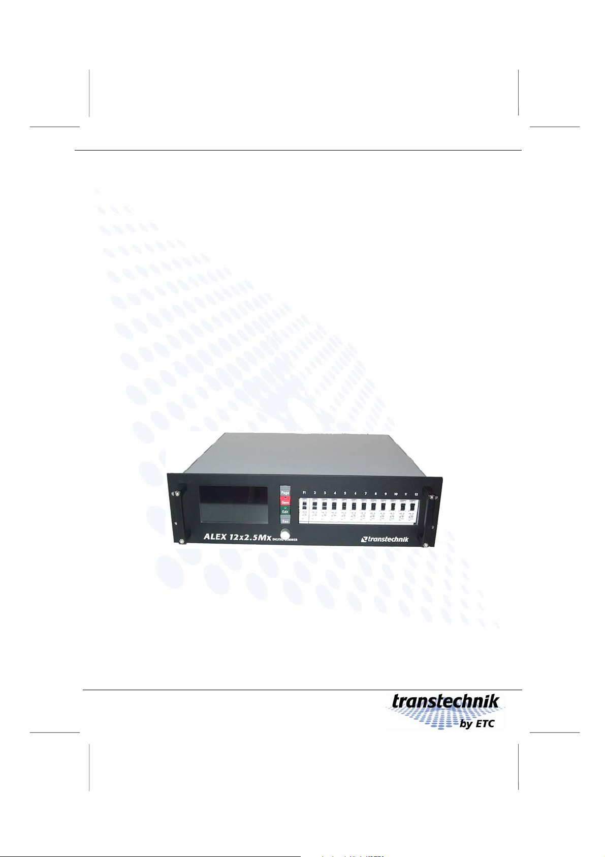
Integrated digital thyristor dimmer
Operating Manual
Alex M /
Alex MX
Manual version 030430-150C
Manual ID no. 7280M1201
ETC – Electronic Theatre Controls
Page 2

Page 3

Operating Manual
Alex M / Alex Mx
Integrated digital thyristor dimmer
© 2000 – 2006 Electronic Theatre Controls GmbH
All rights reserved.
No part of this manual may be reproduced
or copied in any form without the written
approval of Electronic Theatre Controls GmbH.
Technical data subject to change.
Alex M
030430-150B
Alex_M_E_150C_A5.doc
– 3 –
Page 4

Page 5

Alex M Contents
Contents
Meet Alex M.................................................................................................7
First impressions .....................................................................................7
Operation.................................................................................................8
Special features.......................................................................................9
Safety.........................................................................................................10
Symbols.................................................................................................10
Important rules.......................................................................................11
Alex M is very robust, but... ...................................................................12
Lighting in no time with Alex M............................................................... 13
Working with Alex M.................................................................................14
Wiring.....................................................................................................14
Switching the device on.........................................................................15
Controls .................................................................................................15
Keys..................................................................................................15
Rotating knob ...................................................................................16
Preventing improper use of Alex ...........................................................17
Basic settings.........................................................................................18
Language selection ..........................................................................18
Setting the display contrast ..............................................................19
Resetting the dimmer processor ......................................................19
Selecting the source for the dimmer control signals ........................20
Setting the DMX start address .........................................................21
Further basic settings.......................................................................23
Provid i n g s t at i on a ry lightin g (m a n ua l i nt e ns i ty adjustm en t ).................24
Setting the intensity of a channel...........................................................24
Setting the same intensity for all channels............................................25
Saving current output levels as presets ................................................26
Preheating .............................................................................................27
Setting preheating individually for each dimmer channel.................27
Setting the same preheat intensity for all dimmer channels ............28
Intensity limit..........................................................................................29
Setting an intensity limit....................................................................29
Setting the same intensity limit for all dimmer channels ..................30
Dimmer curves.......................................................................................31
Alex M
030430-150B
Alex_M_E_150C_A5.doc
– 5 –
Page 6

Contents Alex M
Assigning a dimmer curve individually for each dimmer
channel .............................................................................................32
Assigning the same dimmer curve to all channels...........................33
Setting the switching threshold for a non-dim curve.........................33
Providing light automatically...................................................................35
Fading in stored presets ........................................................................35
Displaying the contents of stored presets ........................................36
Creating a chase with the chaser function.............................................37
Setting the fade time.........................................................................37
Setting the wait time for presets .......................................................37
Setting a sequence of presets..........................................................38
Running a chase...............................................................................39
Holding/terminating a chase.............................................................40
The menu pages........................................................................................41
Status line.........................................................................................41
Menu page 1: Intensities........................................................................42
Output level display ..........................................................................42
Input/display fields............................................................................43
Menu page 2: Parameters .....................................................................44
Input fields for each individual channel.............................................44
Input fields for each channel individually..........................................45
Input fields for all channels together.................................................45
Menu page 3: Memory/Chaser..............................................................46
Output diagrams...............................................................................46
Input/display fields............................................................................47
Menu page 4: Basic settings..................................................................49
Input/display fields............................................................................49
Software version...............................................................................52
Identifying whether a base load is fitted ...........................................52
Software updates......................................................................................53
Appendix....................................................................................................55
Technical data........................................................................................55
List of factory settings............................................................................58
Pin assignments.....................................................................................59
Pin assignment of the load outputs (HTS plug-in connector)...........59
Pin assignment for the EXT socket ..................................................61
Version status........................................................................................63
– 6 –
Alex M
030430-150B
Alex_M_E_150C_A5.doc
Page 7

Meet Alex M First impressions
g
Meet Alex M
First impressions
Beschreibun
Functions
Features
Alex M allows you to:
• Convert DMX control commands received from the
lighting control system into voltage values for
electrical loads like spotlights
• Save a maximum of twelve presets and make them
available for use.
• Run several presets at the same time with
selectable weightings.
The chaser function allows you to:
• Run entire lighting programs – from chases to
complex sequences of stored presets.
• All common loads controllable
• Selection of three signal sources:
DMX, analog, internally stored presets
• Selection of dimmer characteristics:
Different curves can be defined for each dimmer
channel, including a genuine non-dim function
• Preheat:
Preheating of spotlights of up to 30% independently
for each channel
• Output level limitation:
Between 30% and 100% independently for each
channel
• Precaution in case the input signal fails:
Output of the last preset, one of the twelve stored
presets or synchronizing-dark connection
• Automatic switching to 50 Hz or 60 Hz line
frequency
• Alex MX: Electronic base load allows convenient
dimming of fluorescent lamps.
Alex M
030430-150B
Alex_M_E_150C_A5.doc
– 7 –
Page 8

Operation Meet Alex M
g
Operation
Bedienun
Display
Menu-driven
interface
Status
information
Update
An extremely high-contrast CFL (cathode fluorescent
lamp) backlit display with a visible area of 13 x 7 centimeters and over 30,000 pixels, making it easy to read
even from a considerable distance whatever the
ambient lighting conditions.
You operate Alex M using four keys, a rotating knob
(encoder) and the menus that appear on the display.
Graphical output level displays for each of the six or
twelve channels and plain-text messages or instructions
constantly keep you informed of the current operating
status.
The dimmer processor software is constantly being
further developed. Your dimmer processor can be
updated to match the latest developments at any time.
Alex M
– 8 –
Alex_M_E_150C_A5.doc
030430-150B
Page 9

Meet Alex M Special features
Special features
Thyristors
Fan
Emergency
shutdown
The thyristors, which use phase angle control for the
output voltage, each contain a separate ignition
circuit for the positive and negative half-waves. This
means that the output voltages of each of the dimmer
units have no DC components and makes them
suitable for controlling low-voltage transformers.
A temperature controller ensures that the fan only
ever runs just as fast as is absolutely necessary.
If the temperature level on the dimmer unit gets too
high (e.g. because of a blockage in the air intake),
the device is shut down automatically to prevent
damage due to overheating. Once the temperature
returns to permissible values, the dimmer unit
automatically resumes operation. The loads
connected undergo a soft restart.
Alex M
030430-150B
Alex_M_E_150C_A5.doc
– 9 –
Page 10
Sicherhei
t
Symbols Safety
Safety
Symbols
This manual uses the symbols depicted below for Danger, Caution and
Note. The meanings of these symbols are as follows:
Danger
This symbol indicates situations where failure to follow the
instructions carefully can result in death, injury or accidents.
Caution
This symbol indicates situations where failure to follow the
instructions carefully can cause damage to your equipment.
Note
This symbol is used to draw your attention to a particularly
important passage of text.
Alex M
– 10 –
Alex_M_E_150C_A5.doc
030430-150B
Page 11

Safety Important rules
Important rules
It is not dangerous to work with Alex M. Protective insulation and a whole
series of other protective measures ensure that you cannot come into
contact with any harmful electric currents. However, as with all electrical
equipment, you will need to observe a few simple rules:
• Never switch on equipment that is obviously damaged. Send
the equipment to an authorized dealer or back to the factory
for repairs.
• If there is any reason to suspect a fault, unplug the
equipment from the mains supply immediately. Make sure
that it cannot be started up again and send it to an
authorized dealer or back to the factory for repairs.
• Always unplug equipment from the power supply before
opening it.
• Components inside the equipment can be very hot if they
have only just been switched off.
Repairs are only ever to be made by an authorized dealer or by
transtechnik.
Alex M
030430-150B
Alex_M_E_150C_A5.doc
– 11 –
Page 12

Alex M is very robust, but... Safety
Alex M is very robust, but...
Alex M is designed to cope with the rigors of mobile service, so it will put up
with a lot. Nevertheless, you should still adhere to the following guidelines:
• Only use your equipment for the purpose for which it is
intended.
• Never cover the front and back of your equipment in such
a way that this would impede air circulation (e.g. with
plastic sheeting).
• Ensure that there are always sufficient openings for heat
to be expelled.
• Avoid direct contact with moisture.
– 12 –
Alex M
030430-150B
Alex_M_E_150C_A5.doc
Page 13

Lighting in no time with Alex M 6 or 12 output channels
Lighting in no time with Alex M
• Alex M lets you get down to business straight away. Over the
The screenshots used in this manual depict the menu pages for an
Alex M dimmer unit with twelve output channels. If your Alex M unit
has six output channels, the Intensities, Parameters and Memory/
Chaser menu pages will look rather different owing to the smaller
number of output channels.
next few pages you will find an outline of the major functions
for operating and adjusting the system.
• For detailed information on the menu pages and all the
opportunities afforded by Alex M, please turn to page 41.
• You will find a list of the factory settings on page 58.
Alex M with six or twelve output channels
Alex M
030430-150B
Alex_M_E_150C_A5.doc
– 13 –
Page 14
Wiring Working with Alex M
Working with Alex M
Wiring
Not even Alex M lets you get away without setting up any cable connections:
• A connection to the power supply
• Connections to the required dimmer channels
This is all you need to go ahead and provide lighting with Alex M. If the
dimmers are to be controlled by external signals as well, you also need to
connect the signal source:
Control with
DMX512/1990 signal
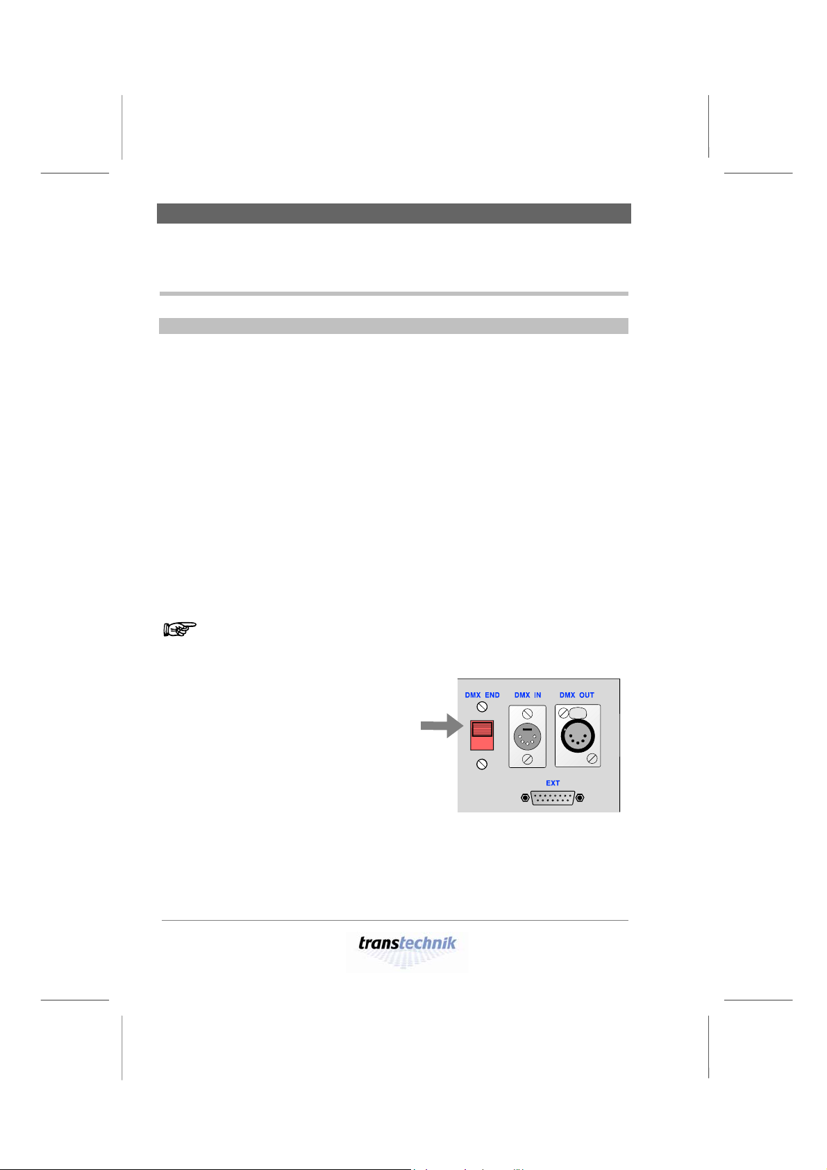
If the DMX OUT socket is left unoccupied, it must be terminated with a
resistor. Set the switch on the backplane of the device to the position "DMX
END". The DMX output socket is now terminated with 100 Ω.
Failure to apply a terminating resistor can lead to errors in DMX
transmission or make such transmission impossible altogether.
When the "DMX END" switch on
the backplane of the device is set
to this position, the DMX output
socket is terminated with 100 Ω.
Connect DMX cables to the DMX IN and DMX
OUT sockets.
Control with
Connect the signal cable to the EXT socket.
0 – 10 V analog signals
For the pin assignment for the EXT socket, see page 61.
– 14 –
Alex M
030430-150B
Alex_M_E_150C_A5.doc
Page 15
Working with Alex M Switching the device on
Switching the device on
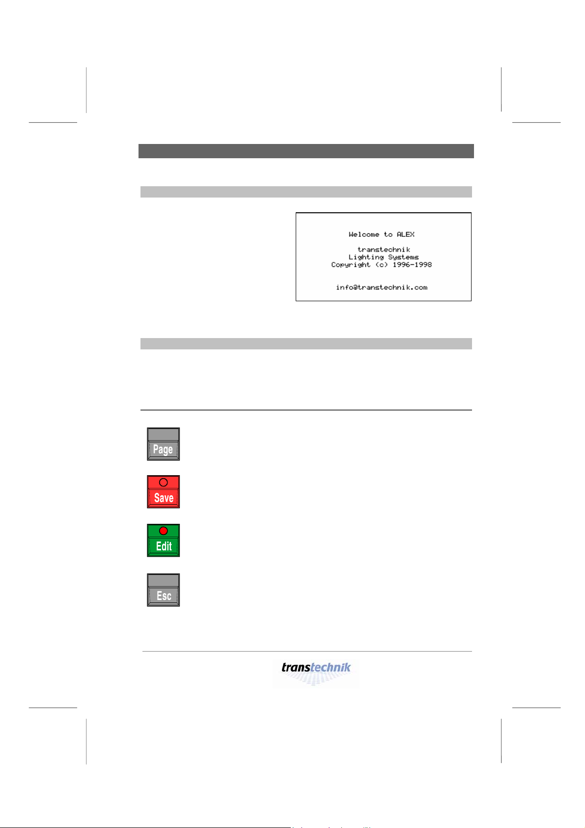
As soon as the power (at
least one phase) has been
switched on, the dimmer
system starts up and the
welcome screen appears on
the display for five seconds.
The first menu page,
Intensities, then appears (see
page 42).
Fig. 1: Welcome screen
Controls
All input is made using 4 keys and a rotating knob (the encoder).
Menus and messages are displayed on a backlit LCD screen.
Keys
Scrolls from one menu page to the next.
Prerequisite: Edit mode must be inactive.
Saves the changes you have made and terminates edit
mode.
Activates edit mode so that entries and changes can be
made.In edit mode you can change values (e.g. dimmer
values).
Terminates edit mode without saving the changes you have
made.
Alex M
030430-150B
Alex_M_E_150C_A5.doc
– 15 –
Page 16
Controls Working with Alex M
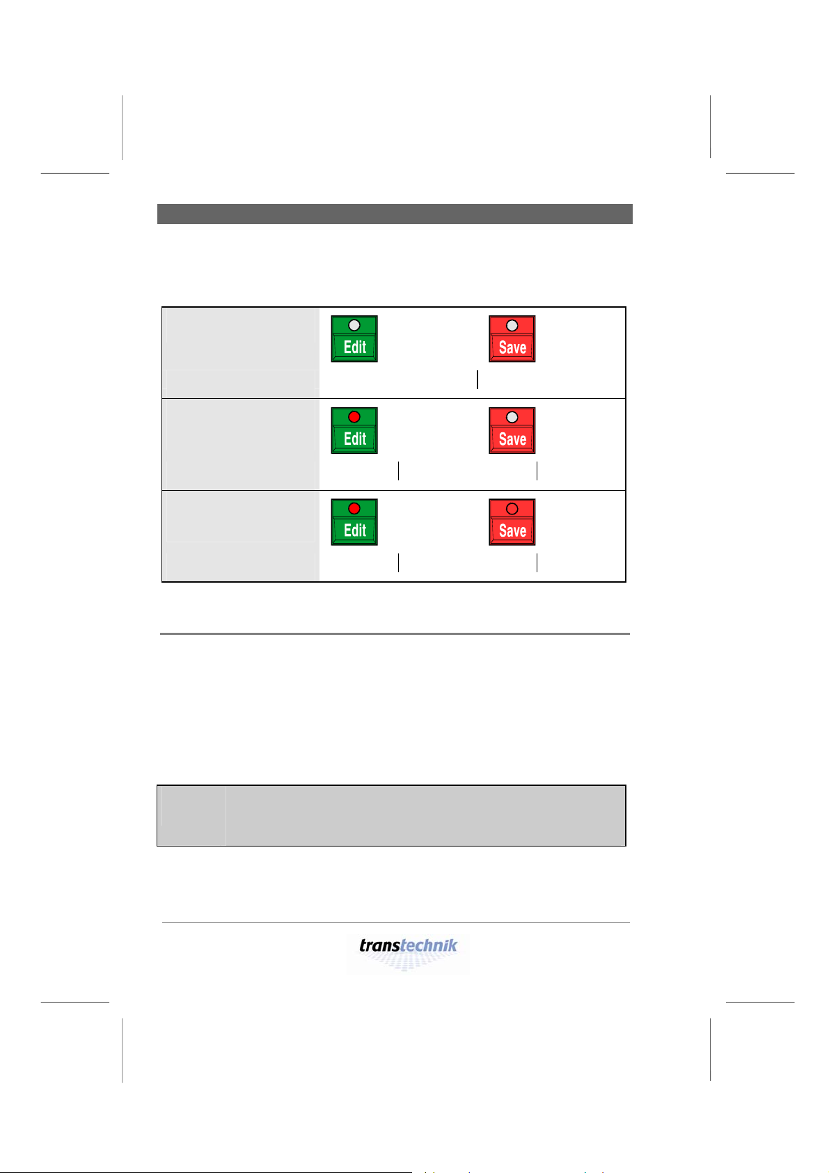
The LEDs in the [Edit] and [Save] keys and the status line at the bottom of
the display provide information on the current input status:
Edit mode
not active
Status line
Edit mode active,
no values
Wheel selects Edit to change
Í LED on
changed yet
Status line
Edit mode active,
at least one
Wheel Save confirms Esc quits
Í LED on
Í LED on
value changed
Status line
Wheel Save confirms Esc quits
Rotating knob
The rotating knob has two modes:
Edit mode inactive
All input fields are displayed one after the other.
The current input field is highlighted.
Edit mode active
The relevant parameter (e.g. numeric value) in
the current input field (highlighted) is changed.
To save space, the rotating knob is referred to simply as a
knob in the menus. The same applies to the rest of this
manual.
– 16 –
Alex M
030430-150B
Alex_M_E_150C_A5.doc
Page 17
Working with Alex M Preventing improper use of Alex
Preventing improper use of Alex
You can secure the device against inadvertent improper use by activating
LOCK mode.
Prerequisite for activating LOCK mode:
EDIT mode must not be active.
1
Switch lock mode on or off by pressing
and holding [Save] and then additionally
pressing [Esc].
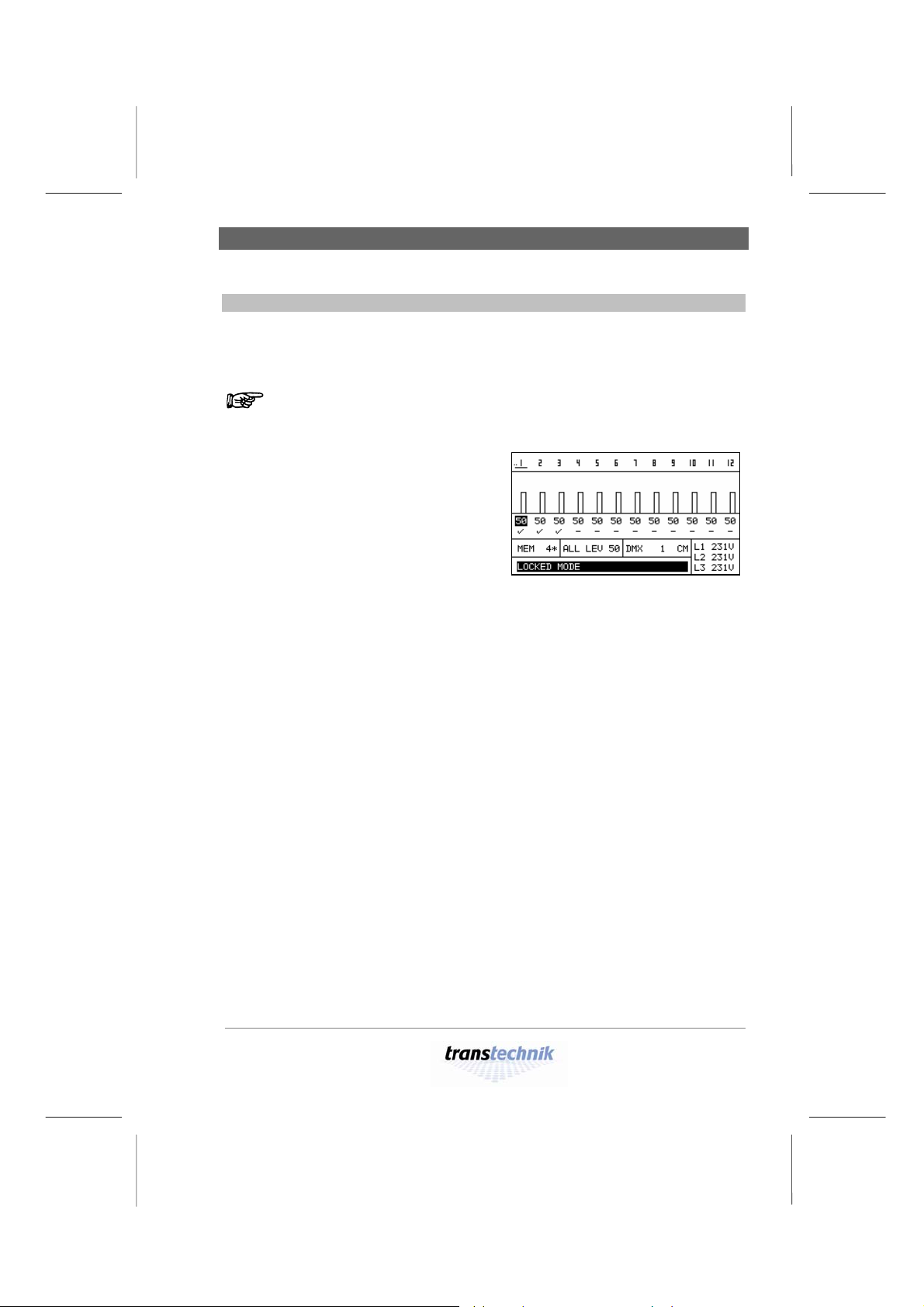
• In LOCK mode, menu page 1,
Intensities, is displayed constantly.
• The text LOCKED_MODE appears
highlighted (Fig. 2).
• Used on their own, none of the four
keys have a function.
• If you turn the knob, this moves the underlining under the DMX address and
the highlighting of the intensity value.
Fig. 2: Display with LOCK mode
activated
Alex M
030430-150B
Alex_M_E_150C_A5.doc
– 17 –
Page 18
Basic settings Working with Alex M
Basic settings
Before you start, you can rest assured:
The device is ready for operation immediately even if you don’t
make any basic settings.
Before you start working with Alex M, you should nevertheless have a look
at selected basic settings (there are a total of 12). You can use them to
customize Alex M to suit your exact requirements.
To make working with the device easier for you, you can set the menu
language and display contrast, for example. Then select the signal source
and the DMX start address. The reset function allows you, if you wish, to
reset the device to the factory settings.
These five steps are described on the following pages.
Grundeinstellungen
Language selection
Currently, the menu texts can be displayed in five languages:
English – German – Dutch – Italian – Spanish.
The factory setting is English. To set another language, proceed as follows:
1
Press [Page] until menu page 4, Basic
Settings, appears.
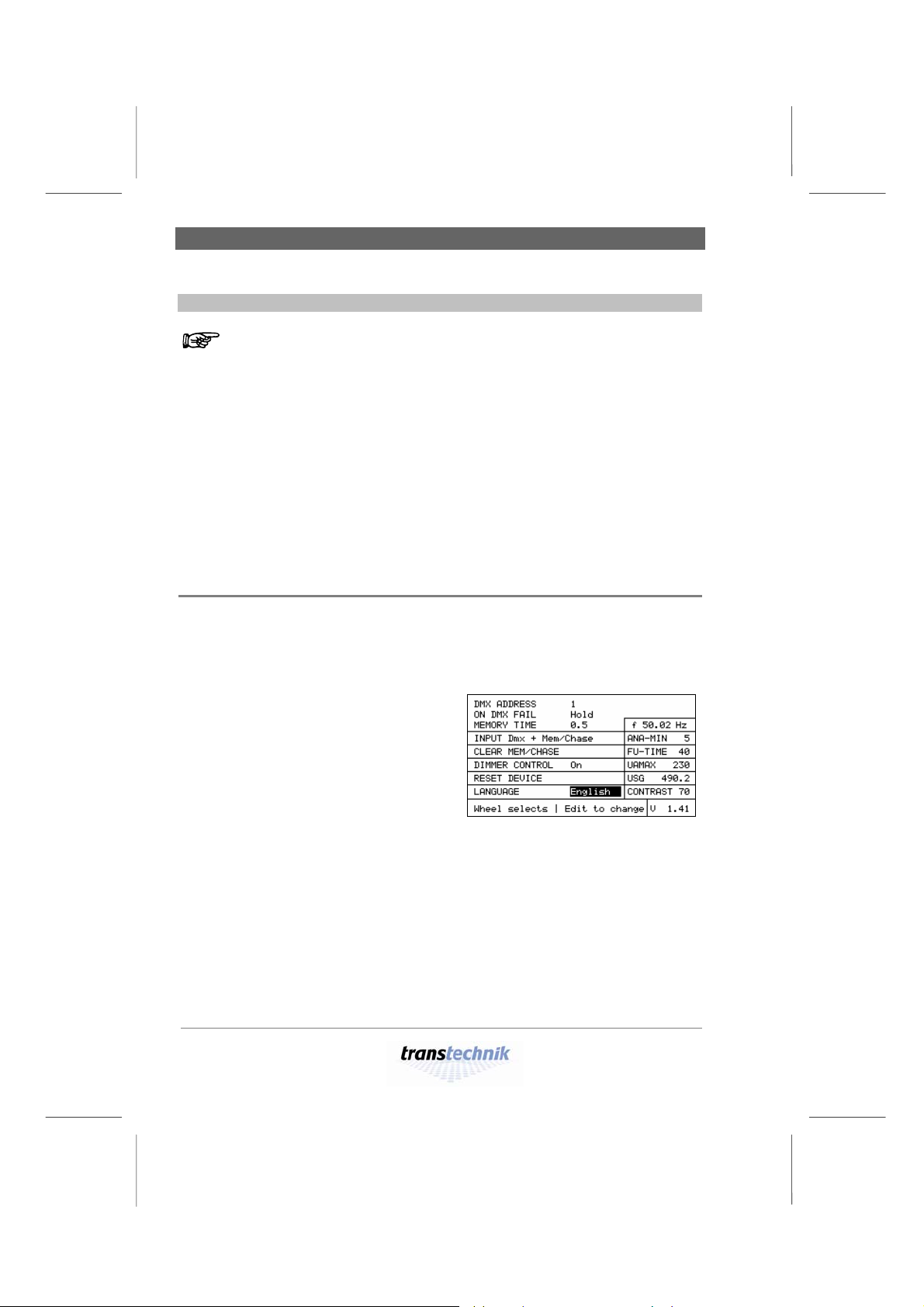
2 Turn the knob until the LANGUAGE
field is highlighted.
• The currently set language is
highlighted.
3 Press [Edit].
4 Use the knob to select a language.
5 Use [Save] to save the language you
have selected.
Fig. 3: Basic Settings menu
Active field: LANGUAGE
– 18 –
Alex M
030430-150B
Alex_M_E_150C_A5.doc
Page 19
Working with Alex M Basic settings
Setting the display contrast
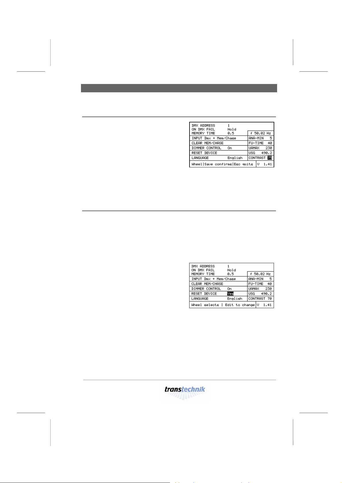
1 Press [Page] until menu page 4, Basic
Settings, appears.
2 Turn the knob until the CONTRAST
field is highlighted.
3 Press [Edit].
4 Use the knob to set the desired
contrast (factory setting: 75).
5 Press [Edit].
• The contrast setting is saved.
Fig. 4: Basic Settings menu
Active field: CONTRAST
Resetting the dimmer processor
The reset function resets all settings and parameters to the factory settings.
In particular:
• All dimmer parameters are reset.
• All the stored presets are reset to zero.
• The language is set to English.
1
Press [Page] until menu page 4, Basic
Settings, appears.
2 Turn the knob until the RESET DEVICE
field is highlighted.
• Yes is the highlighted default value.
3 Press [Edit].
4 Use the knob to select
– Yes for reset or
– No for do not reset.
Fig. 5: Basic Settings menu
Active field: RESET DEVICE
Alex M
030430-150B
Alex_M_E_150C_A5.doc
– 19 –
Page 20
Basic settings Working with Alex M
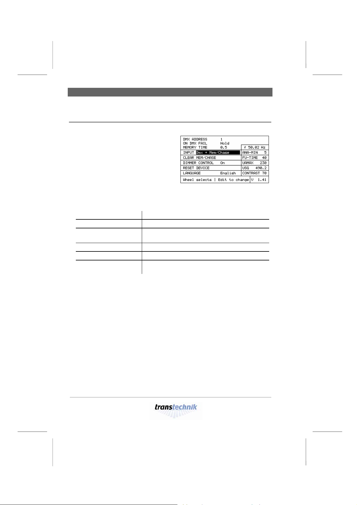
Selecting the source for the dimmer control signals
1
Press [Page] until menu page 4, Basic
Settings, appears.
2 Turn the knob until the INPUT field is
highlighted.
3 Press [Edit].
4 Use the knob to select a signal source.
(Factory setting:
Dmx + Mem/Chase)
Fig. 6: Basic Settings menu
Active field: INPUT
Dmx
Analog
Mem/Chase
Dmx + Mem/Chase
Analog + Mem/Chase
Ana+Dmx+Mem/Chase
External device via DMX signal
External device via analog signal
Alex M
(manual control, stored presets, chases)
External device via DMX signal and Alex M
External device via analog signal and Alex M
External devices via analog signal, DMX signal and
Alex M
5 Press [Save] to save the setting for the selected signal source.
– 20 –
Alex M
030430-150B
Alex_M_E_150C_A5.doc
Page 21

Working with Alex M Basic settings
Setting the DMX start address
There are two ways to set the DMX addresses:
• All twelve channels receive a DMX address, which is incremented in
ascending order from the start address.
• Each of the twelve channels receives its own address.
Setting a sequence of DMX addresses in ascending order
1
Press [Page] until menu page 4, Basic
Settings, appears.
2 Turn the knob until the DMX ADDRESS
field is highlighted.
3 Press [Edit].
4 Turn the knob clockwise to set the
desired DMX start address
(Factory setting: 1).
5 Press [Save].
• The selected start address is saved.
• Each channel receives the address corresponding to its channel number
incremented from the start address.
• The resulting DMX addresses are then displayed on
menu page 1, Intensities.
Fig. 7: Basic Settings menu
Active field: DMX ADDRESS
Alex M
030430-150B
Alex_M_E_150C_A5.doc
– 21 –
Page 22

Basic settings Working with Alex M
Assigning each channel an individual DMX address
1
Press [Page] until menu page 4, Basic
Settings, appears.
2 Turn the knob until the DMX ADDRESS
field is highlighted.
3 Press [Edit].
4 Turn the knob counterclockwise until
the SINGLE setting appears.
5 Press [Save].
• The setting SINGLE is saved, and the next line is highlighted.
Fig. 8: Basic Settings menu
Active field: DMX ADDRESS
Selected: SINGLE
6 Press [Page].
• The field for entering addresses
individually appears.
7 Use the knob to highlight a channel,
and then press [Edit].
8 Use the knob to set the DMX address.
9 Repeat this procedure for each of the
twelve channels.
Fig. 9: Entering addresses
individually
The LINEAR field in the lower left corner of the display allows you to enter
a start address as of which the channels receive addresses in ascending
order. This entry thus corresponds to the method described in the previous
section.
Fig. 10: Appearance of menu page 1,
Intensities, when DMX addresses have
been assigned to the channels
individually.
If individual DMX adresses are assigned, the individual adresses page
(Fig. 9) appears as fifth menu page when scrolling with [Page].
Alex M
– 22 –
Alex_M_E_150C_A5.doc
030430-150B
Page 23

Weitere Grundeinstellungen
Working with Alex M Basic settings
Further basic settings
Further basic settings can be made on menu page 4, Basic Settings, in the
same way as described in the previous pages:
Setting Entry field
Behavior if DMX signal fails ON DMX FAIL
Fade-in time for the selected auxiliary group if
MEMORY TIME
the DMX signal fails
Minimum value for dimmer control via analog signal
Resetting of all preset and chase parameters
ANA-MIN
CLEAR MEM/CHASE
Fade-in time for intensity increments FU-TIME
Dimmer control on/off DIMMER CONTROL
Maximum output voltage UAMAX
For explanations and selection options: See the section entitled Menu page
4: Basic settings on page 49.
The USG field on menu page 4, Basic Settings, is not an input
field; it merely indicates the operating time in hours.
Alex M
030430-150B
Alex_M_E_150C_A5.doc
– 23 –
Page 24

Setting the intensity of a channel Providing stationary lighting
Providing stationary lighting (manual intensity adjustment)
Alex M with six or twelve output channels
The screenshots used in this manual depict the menu pages for an
Alex M dimmer unit with twelve output channels. If your Alex M unit
has six output channels, the Intensities, Parameters and Memory/
Chaser menu pages will look rather different owing to the smaller
number of output channels.
Intensität einstellen
Setting the intensity of a channel
The description that follows explains how to set the intensity of a single
dimmer channel.
1
On menu page 4, Basic Settings, select
Mem/Chase as the signal source (see
page 19).
2 Press [Page] to call menu page 1,
Intensities.
3 Use the knob to select the (dimmer)
channel you require.
• The dimmer channel number is
underlined in the uppermost line
(1 in the figure); the current setting is
selected (56 in the figure).
Fig. 11:
Setting the intensity of a channel
4 Press [Edit] and use the knob to set the desired intensity value.
• The setting takes effect immediately and is displayed in the form of a
transparent bar and a numeric value. Value range: 0 to FF (0% to 100%).
5 Press [Save] to save the setting.
– 24 –
Alex M
030430-150B
Alex_M_E_150C_A5.doc
Page 25

Providing stationary lighting Setting the same intensity for all channels
Setting the same intensity for all channels
1 Press [Page] to call menu page 1,
Intensities.
2 Use the knob to select the ALL LEV
function.
• The current setting is selected (75 in
the figure).
3 Press [Edit] and use the knob to set the
desired value.
• The setting takes effect immediately and is displayed in the form of a
transparent bar with a numeric value for each channel. Value range: 0 to FF
(0% to 100%).
Fig. 12: ALL LEV function
4 Press [Save] to save the setting.
If you find that you are unable to go below a certain value when
changing the output level, it may be because:
• At least one stored preset or chase is activated (see menu page 3,
Memory/Chaser, on page 46)
• Mem/Chase is not selected as the signal source. Example:
− Selected signal source: DMX
− Selected response in the event of a DMX failure: preset 2
− No DMX signal
º The stored preset 2 is thus active.
Output level values that are determined by activated presets can be
increased by making settings on menu page 1, Intensities, but never
reduced (HTP principle: highest takes precedence).
Similarly, intensity values that are determined by an external signal
source can also only be increased but never reduced. External
intensity values are shown on menu page 1, Intensities, by means of
solid bars.
Alex M
030430-150B
Alex_M_E_150C_A5.doc
– 25 –
Page 26

Saving current output levels as presets Providing stationary lighting
Saving current output levels as presets
This function saves the current intensity settings as a preset – irrespective
of its composition in terms of external and internal intensities (solid and
transparent bars).
Press [Page] to call menu page 1,
1
Intensities.
2 Use the knob to select the MEM
function.
3 Press [Edit] and use the knob to set the
desired memory block number (from 1
to 12).
• Memory blocks to which presets are
already assigned are indicated by an
asterisk (=).
Fig. 13: MEM function
4 Press [Save] to save the current intensities as a preset under the selected
number (no. 4 in the figure).
Any preset that was already assigned to this memory block (=) will be
overwritten.
– 26 –
Alex M
030430-150B
Alex_M_E_150C_A5.doc
Page 27

Providing stationary lighting Preheating
Preheating
Setting preheating individually for each dimmer channel
The preheat intensity can be adjusted in 0.1% steps in the range from 0 to
10%. Above 10% you can change the value in 1% steps.
1
Press [Page] to call menu page 2,
Parameters.
2 Use the knob to move the selection
cursor to the PRE row and to the
desired channel in this row.
3 Press [Edit] and use the knob to set the
desired percentage for the preheat
intensity (15% in the figure).
• The setting takes effect immediately.
Value range:
0 to 30%
Fig. 14:
Setting the preheat intensity value
4 Press [Save] to save the currently selected preheat intensity.
Set preheat intensity values are constantly output to the corresponding
channels but do not appear in the bar chart on menu page 1, Intensities.
Alex M
030430-150B
Alex_M_E_150C_A5.doc
– 27 –
Page 28

Preheating Providing stationary lighting
Setting the same preheat intensity for all dimmer channels
1
Press [Page] to call menu page 2,
Parameters.
2 Use the knob to move the selection
cursor to the ALL input field.
3 You can set the same values here for
all channels for the following:
− Preheat (PRE)
− Intensity limit (LIM)
− Dimmer curve (DCU)
Fig. 15: Setting the same preheat
intensity for all channels
4 Turn the knob until ALL PRE appears.
• The currently set preheat intensity value is highlighted (5.0 in the figure).
5 Press [Edit] and use the knob to set the desired preheat intensity value.
The preheat intensity can be adjusted in 0.1% steps in the range from 0 to 10%.
Above 10% you can change the value in 1% steps.
6 Press [Save] to save the currently selected preheat intensity value for all
channels.
– 28 –
Alex M
030430-150B
Alex_M_E_150C_A5.doc
Page 29

Providing stationary lighting Intensity limit
Intensity limit
Setting an intensity limit
1
Press [Page] to call menu page 2,
Parameters.
2 Use the knob to move the selection
cursor to the LIM row and to the desired
channel in this row.
3 Press [Edit] and use the knob to set the
desired limit intensity value
(FF = 100% in the figure).
• The setting takes effect immediately.
Value range: 0 to FF
(0% to 100%)
Fig. 16: Setting an intensity limit
4 Press [Save] to save the currently selected limit intensity value.
Set limit intensity values are not taken into account in the bar chart on
menu page 1, Intensities. If a given channel is limited to 90%, for example,
a maximum of 90% is output – even if menu page 1, Intensities, indicates
a higher value for this channel.
Alex M
030430-150B
Alex_M_E_150C_A5.doc
– 29 –
Page 30

Intensity limit Providing stationary lighting
Setting the same intensity limit for all dimmer channels
1
Press [Page] to call menu page 2,
Parameters.
2 Use the knob to move the selection
cursor to the ALL input field.
3 You can set the same values here for
all channels for the following:
− Preheat (PRE)
− Intensity limit (LIM)
− Dimmer curve (DCU)
Fig. 17: Setting the same intensity
limit for all channels
4 Turn the knob until ALL LIM appears.
• The currently set limit intensity value is highlighted (90 in the figure).
5 Press [Edit] and use the knob to set the desired limit intensity value.
6 Press [Save] to save the currently selected limit intensity value for all channels.
– 30 –
Alex M
030430-150B
Alex_M_E_150C_A5.doc
Page 31

Providing stationary lighting Dimmer curves
Dimmer curves
The dimmers are controlled using characteristic curves. A curve assigns
each output level (e.g. 50%) to a specified 'real' dimmer level. The dimmer
curve can be used to modify the dimming behavior of a spotlight to the
given requirements (e.g. to come on when a particular threshold value is
achieved, unlike linear control).
All dimmer curves refer to the power output. Characteristic curve LI “linear”
thus means “linear power output”.
You can assign a specific dimmer curve to each dimmer channel.
You can choose between five curves:
Linear = linear power
LI
output
Halogen
SC
Currently not implemented, behaves as LI = linear power output
For fluorescent lamps
EX
100
90
80
70
60
50
40
30
20
Output power (%)
10
0
1
1631466176
91
106
121
136
151
166
181
196
211
226
241
Input
100
90
80
70
60
50
40
30
20
Output power (%)
10
0
1
1631466176
91
106
121
136
151
166
181
196
211
226
241
256
Input
256
Alex M
030430-150B
Alex_M_E_150C_A5.doc
– 31 –
Page 32

Dimmer curves Providing stationary lighting
Logarithmic or voltage
LG
linear,
for 115 V at an output
level of 50%
Non-Dim (switching curve)
ND
100
90
80
70
60
50
40
30
Output power (%)
20
10
0
1
1631466176
91
106
121
136
151
166
181
196
211
226
241
Input
256
100
90
80
70
60
50
40
30
Output pow er (%)
20
10
0
1
1631466176
91
106
121
136
151
166
181
196
211
226
241
Input
256
Assigning a dimmer curve individually for each dimmer channel
1 Press [Page] to call menu page 2,
Parameters.
2 Use the knob to move the selection
cursor to the DCU row and to the
desired channel in this row.
3 Press [Edit] and use the knob to set the
desired dimmer curve.*
4 Press [Save] to save the currently
selected dimmer curve (ND for non-dim
on channel 5 in the figure).
As you turn the knob, four unassigned characteristic curve storage locations (--)
*)
appear between the LG and ND curves.
– 32 –
Fig. 18: Assigning a dimmer curve
individually
030430-150B
Alex_M_E_150C_A5.doc
Alex M
Page 33

Providing stationary lighting Dimmer curves
Assigning the same dimmer curve to all channels
1 Press [Page] to call menu page 2,
Parameters.
2 Use the knob to move the selection
cursor to the ALL input field.
3 You can set the same values here for
all channels for the following:
− Preheat (PRE)
− Intensity limit (LIM)
− Dimmer curve (DCU)
Fig. 19: Assigning the same dimmer
curve to all dimmer channels
4 Turn the knob until ALL DCU appears.
• The currently set dimmer curve is highlighted (LI in the figure).
5 Press [Edit] and use the knob to set the desired dimmer curve (LI, SC, EX, LG or
ND; see page 31).*
6 Press [Save] to save the dimmer curve selected for all channels.
As you turn the knob, four unassigned characteristic curve storage locations (--)
*)
appear between the LG and ND curves.
Setting the switching threshold for a non-dim curve
1 Press [Page] to call menu page 2,
Parameters.
2 Use the knob to move the selection
cursor to the THRESHLD input field.
3 Press [Edit] and use the knob to set the
desired switching threshold (applies to
all channels with a non-dim curve).
• Value range: 5 to 95
4 Press [Save] to save the switching
threshold selected for all channels.
Fig. 20: Setting the switching
threshold for a non-dim curve
Alex M
030430-150B
Alex_M_E_150C_A5.doc
– 33 –
Page 34

– 34 –
Alex M
030430-150B
Alex_M_E_150C_A5.doc
Page 35

Providing light automatically Fading in stored presets
Providing light automatically
Fading in stored presets
You can fade in several stored presets with individually selected
weightings.
1
Press [Page] to call menu page 3,
Memory/Chaser.
2 Use the knob to move the selection
cursor to the MEM row and to the
desired preset in this row
(3 in the figure).
• The bar chart displays the individual
intensities of this preset.
3 Press [Edit] and use the knob to set the
desired output level (weighting factor)
for the selected preset:
• Value range: 0 to FF (0% to 100%).
The weighting factor is displayed in three forms:
• As a wide bar in the OUT field
• As a numerical value in the OUT field (60% in the figure)
• As a narrow bar under the number of the preset
4 Press [Save] to save the selected weighting factor.
The bar and the numeric value in the OUT field apply only to the selected
preset. By contrast, the narrow bars under the preset number constantly
display the weighting factors for the presets. This enables you to identify at
a glance which presets are contributing how much to the current lighting
scene.
Fig. 21: Bar chart with the intensities
of a preset
Alex M
030430-150B
Alex_M_E_150C_A5.doc
– 35 –
Page 36

Fading in stored presets Providing light automatically
While the presets are faded in, output levels from other settings or
sources continue to be output:
• Internally:
Manual output levels created using menu
page 1, Intensities
• Externally:
Output levels determined by other signal
sources
If you want to output all presets that have been stored alone,
the following prerequisites must be met:
• Signal source: Mem/Chase
• All manually created output levels must be at zero
Displaying the contents of stored presets
1
Press [Page] to call menu page 3,
Memory/Chaser.
2 Use the knob to move the selection
cursor to the MEM row and to the
desired preset in this row
(preset 3 in the figure).
• The bar chart displays the intensities
of this preset.
Fig. 22: Bar chart with the intensities
of preset 3
– 36 –
Alex M
030430-150B
Alex_M_E_150C_A5.doc
Page 37

Providing light automatically Creating a chase with the chaser function
Creating a chase with the chaser function
Setting the fade time
The fade time is the time taken for the first preset to fade in, for the first
preset to crossfade to the second, and so on.
1
Press [Page] to call menu page 3,
Memory/Chaser.
2 Use the knob to move the selection
cursor to the FADE field.
3 Press [Edit] and use the knob to set the
desired fade time (0.0 seconds in the
figure).
• Applies to all presets.
• Value range: 0.0 to 999.0 (seconds)
Fig. 23: Setting the fade time
4 Press [Save] to save the selected fade time.
Setting the wait time for presets
The wait time is the period of time for which each preset remains on at full
power in the case of chase lighting.
1
Press [Page] to call menu page 3,
Memory/Chaser.
2 Use the knob to move the selection
cursor to the SPEED field.
3 Press [Edit] and use the knob to set the
desired wait time of the presets
(1.0 seconds in the figure).
• Applies to all presets.
• Value range: 0.0 to 999.0 (seconds)
Fig. 24: Setting the wait time
4 Press [Save] to save the selected wait time.
Alex M
030430-150B
Alex_M_E_150C_A5.doc
– 37 –
Page 38

Creating a chase with the chaser function Providing light automatically
Setting a sequence of presets
You can define a sequence of 1 to a maximum of 12 presets in any order.
The SEQ row on menu page 3, Memory/Chaser, contains 12 positions for
this purpose that are prefilled with the 12 storable presets in ascending
order (factory setting). However, any preset can be assigned to each of
these sequence positions.
1
Press [Page] to call menu page 3,
Memory/Chaser.
2 Use the knob to move the selection
cursor to the SEQ row and to the
desired sequence position in this row.
3 Press [Edit] and use the knob to set the
desired preset number at this sequence
position
(preset no. 3 in the figure).
• Value range: . ., 1 to 12
• Two dots (. .) conclude a sequence that has less than 12 presets.
Fig. 25: Assigning a sequence
position
4 Press [Save] to save the selected preset or the characters concluding the
sequence (. .) at the current sequence position.
Example:
You want to run the following sequence:
Preset 7 – preset 2 – preset 12
Enter it in the SEQ row, as shown in Fig. 26.
• The sequence is executed as follows:
7 – 2 – 12 –
7 – 2 – 12 –
7 – 2 – 12 –
...
Fig. 26: Sequence of three as an
example
– 38 –
Alex M
030430-150B
Alex_M_E_150C_A5.doc
Page 39

Providing light automatically Creating a chase with the chaser function
Running a chase
1 Press [Page] to call menu page 3,
Memory/Chaser.
2 Use the knob to move the selection
cursor to the CHASE field.
• The current status (STOP) is
selected.
3 Press [Edit].
• The status display changes to GO.
Fig. 27: Running a chase
Press [Save] to activate the chase.
4
What you see on the display while the chaser function is active:
CHASE GO → XX =
Crossfade
from one preset to the next
Chaser
function active
Current preset or next preset
Press [Page] twice to switch to menu page 1, Intensities, in order to
be able to follow the execution of the lighting sequence in the bar
chart.
While the presets are faded in, output levels from other settings or
sources continue to be output:
• Internally:
• Externally:
Manual output levels created using menu
page 1, Intensities
Output levels determined by other signal
sources
If you want to output all presets that have been stored alone,
the following prerequisites must be met:
• Signal source: Mem/Chase
• All manually created output levels must be at zero
Alex M
030430-150B
Alex_M_E_150C_A5.doc
– 39 –
Page 40

Creating a chase with the chaser function Providing light automatically
Holding/terminating a chase
1 Press [Page] to call menu page 3,
Memory/Chaser.
2 Use the knob to move the selection
cursor to the CHASE field.
• The current status (GO__XX =) is
selected.
3 Press [Edit].
• The number of the preset that has
just been output disappears, but the
chaser function remains active.
Fig. 28: Holding a chase
4 Use the knob:
• To set the HOLD function to hold the chase.
The current output values are retained.
• To set the STOP function to terminate the chase.
The chase is faded out immediately.
Difference:
• HOLD: [SAVE] holds the chaser function; the current output values are retained.
• STOP: [SAVE] terminates the chaser function; the chase is faded out
immediately.
5 Press [Save] to activate the selected function (HOLD or STOP).
Every time the chaser function restarts, it begins with the first preset in the
sequence, irrespective of whether HOLD or STOP was active last.
– 40 –
Alex M
030430-150B
Alex_M_E_150C_A5.doc
Page 41

The menu pages Status line
The menu pages
In conjunction with the keypad and the knob, four menu pages (shown here
for an Alex M with 12 channels) allow you to make all the entries you need
and keep you in the picture at all times regarding the current operating
status of Alex M:
Menu page 1: Intensities
(see page 42)
Menu page 2: Parameters
(see page 44)
Menu page 3: Memory/Chaser
(see page 46)
Menu page 4: Basic Settings
(see page 49)
You press [Page] to cycle through these 4 menu pages. The
welcome screen only appears when the device has been
booted.
Status line
All menu pages have a status line along the bottom edge of the display.
This is where help texts and error messages are displayed.
During normal operation, the status line displays the following texts:
Wheel selects | Edit to change (edit mode inactive)
or
Wheel | Save confirms | Esc quits (edit mode active)
Alex M
030430-150B
Alex_M_E_150C_A5.doc
– 41 –
Page 42

Menu page 1: Intensities The menu pages
Menu page 1: Intensities
Menu page 1, Intensities, constantly displays the current output levels for
all dimmer channels in a bar chart.
Fig. 29: Menu page 1,
Intensities, for a
configuration with 12 dimmers. When there are
6 dimmers, you will, of
course, only see six channelspecific indicators (e.g. bars).
Output level display
Menu page 1, Intensities, constantly displays the current output levels for
all dimmer channels in a bar chart. Each bar is split into two:
Left half (solid)
Contribution made by other, external devices (DMX or
analog) to the output level
Right half
(transparent)
Contribution made internally by Alex M to the output
level (stored presets, chases).
The output value displayed is always whichever of the external and the
internal contributions is the higher.
– 42 –
Alex M
030430-150B
Alex_M_E_150C_A5.doc
Page 43

The menu pages Menu page 1: Intensities
Input/display fields
1st row
under bar chart
Value range:
2nd row
under bar chart
Contribution made by Alex M to the output levelSpecified
in percent for each channel
0 to FF (0% to 100%)
Factory setting:
All 0
Status display, entry for each channel
Circuit closed, no error
− Circuit open (no lamp connected,
spotlight defective)*
E Fuse triggered
MEM X=
ALL LEV
DMX 1 CM
P Phase error
Input field for saving the current output level as a preset
X Memory block, value range: 1 to 12
= Memory block is assigned
Input field: The same internal output level can be assigned to all channels.
Indicates the signal source, which can be any of the
following:
DMX xxx CM DMX and Memory/Chaser or
analog, DMX and Memory/Chaser
L1 230V
L2 230V
L3 230V
DMX xxx - - DMX only
ANA - - - CM Analog and Memory/Chaser
ANA - - - - - Analog only
- - - - - - CM Memory/Chaser only
xxx = DMX start address
Memory/Chaser = stored presets/chases
Displays the current phase voltages.
- - - Phase missing
*) The display ”-” (Circuit open) is not available on units fitted with an
electronic base load.
Alex M
030430-150B
Alex_M_E_150C_A5.doc
– 43 –
Page 44

Menu page 2: Parameters The menu pages
Menu page 2: Parameters
This menu page shows the individual dimmer parameters for each channel
and allows you to modify them.
Fig. 30: Menu page 2,
Parameters, for a
configuration with 12 dimmers. When there are
6 dimmers, you will, of
course, only see six
channel-specific displays
(e.g. bars).
Input fields for each individual channel
PRE
LIM
DCU
Preheat for spotlights
Value range:
Factory setting:
0 to 30
All 0
Output level limit
Value range:
Factory setting:
30 to FF (30% to 100%)
All FF
Dimmer curve, possible settings:
LI
SC
EX
LG
- ND
Factory setting:
Linear
Halogen
Fluorescent lamps
Logarithmic
(not assigned)
Non-Dim (switched dimmer
curve)
All LI
Dimmer curves: see page 31.
– 44 –
Alex M
030430-150B
Alex_M_E_150C_A5.doc
Page 45

The menu pages Menu page 2: Parameters
Input fields for each channel individually
LEV
Internal contribution to the output level
Value range: 0 to FF (0% to 100%)
STA
Status display
Circuit closed, no error
Circuit open (no lamp connected, spotlight
−
defective)*
Fuse triggered
E
Phase error
P
The symbol is also displayed if a lamp is not
connected and output exceeds 90%.
*) The display ”-” (Circuit open) is not available on units fitted with an
electronic base load.
Input fields for all channels together
CLR
Yes [Save] resets all the parameters on this page to their
factory settings (see page 58).
ALL PRE
ALL LIM
ALL DCU
You can assign all channels the same:
− Preheat values
− Output level limits
− Dimmer curves
The value ranges are as for PRE, LIM and DCU (see
previous page).
THRESHLD
Value range:
Switching threshold for a non-dim curve
5 to 95
Factory setting:
10
Alex M
030430-150B
Alex_M_E_150C_A5.doc
– 45 –
Page 46

Menu page 3: Memory/Chaser The menu pages
Menu page 3: Memory/Chaser
Menu page 3, Memory/Chaser, allows you to activate stored presets
statically or as chases.
Fig. 31: Menu page 3,
Memory/Chaser for a
configuration with 12 dimmers. When there are
6 dimmers, you will, of
course, only see six
channel-specific indicators
(e.g. bars).
Output diagrams
For the currently selected preset, the bar charts indicate:
• The (internal) output for each channel
• The percentage to which this preset is activated and is therefore
contributing to the current lighting
These values are also displayed in numeric form.
– 46 –
Alex M
030430-150B
Alex_M_E_150C_A5.doc
Page 47

The menu pages Menu page 3: Memory/Chaser
Input/display fields
OUT
Contribution made by the selected preset to the current
lighting. A bar shows you at a glance the weighting
factor applied for the preset.
Value range:
Factory setting:
0 to FF (0% to 100%)
0
MEM
List of stored presets (12 memory blocks). The
weighting factor (the contribution made by a given
preset to the current lighting) is displayed as a small bar
under the preset number. The same applies to presets
that are not selected.
FADE
Fade time for the chaser function: This is the time taken
for the first preset to fade in, for the first preset to
crossfade to the second, and so on. The fade time
applies to all presets.
Value range:
Factory setting:
0.0 to 999.0 (seconds)
0.0
SPEED
Wait time for individual presets in the case of chases
Value range:
Factory setting:
1.0 to 999.0 (seconds)
0.0
Alex M
030430-150B
Alex_M_E_150C_A5.doc
– 47 –
Page 48

Menu page 3: Memory/Chaser The menu pages
Input/display fields (continued)
CHASE
Activates, holds and terminates the chaser function.
GO [Save] starts the chaser function.
HOLD [Save] holds the chaser function; the current
output values are retained.
STOP [Save] terminates the chaser function.
Crossfade
SEQ
What you see on the display while the chaser function
is active:
CHASE GO → XX =
Chaser
from one preset to the next
function active
Current
preset or next preset
Sequence of stored presets that can be output using
the chaser function. The sequence can contain up to
12 presets.
Value range:
Factory setting:
. .
. ., 1 to 12
1 2 3 ... 12
Concludes a sequence which
contains less than 12 entries.
CLR
_Yes_
[Save] sets the weighting factors (OUT) of all
presets to zero and terminates the chaser
function, if it is active.
The contents of the presets are retained.
– 48 –
Alex M
030430-150B
Alex_M_E_150C_A5.doc
Page 49

The menu pages Menu page 4: Basic settings
Menu page 4: Basic settings
This menu page shows the basic settings for the dimmer system and
allows you to modify them.
Fig. 32: Menu page 4,
Basic Settings
Input/display fields
DMX ADDRESS
ON DMX FAIL
DMX start address of the dimmer system
Value range:
Factory setting:
1 to 512 and SINGLE
1
Behavior if the DMX signal fails
(detected after 2 seconds)
Hold Maintains the current output levels
Memory XX Fades in the stored preset XX
Only effective if DMX + Mem/Chase is
selected as the signal source under INPUT.
Chaser Chaser function active (chase)
Only effective if DMX + Mem/Chase is
selected as the signal source under INPUT.
Blackout Deactivates all channels.
Factory setting: Hold
Alex M
030430-150B
Alex_M_E_150C_A5.doc
– 49 –
Page 50

Menu page 4: Basic settings The menu pages
Input/display fields (continued)
MEMORY TIME
Fade-in time for preset XX if the DMX signal fails
FREQ
Display of mains frequency
Display only. This is not an input field and cannot be
addressed with the knob.
INPUT
Source of the dimmer control signals
Dmx DMX signal only
Analog Analog signal only
Mem/Chase Stored presets or chases only
Dmx + Mem/Chase DMX signal and stored
presets/chases
Analog + Mem/Chase Analog signal and stored
presets/chases
Ana+Dmx+Mem/Chase
Analog signal, DMX signal and
stored presets/chases
Factory setting: Dmx + Mem/Chase
ANA-MIN
CLEAR
MEM/CHASE
Minimum value for output level through analog signal in
percent. Below this value: output = zero.
Value range:
Factory setting:
5 to 10
5
_Yes_ + [Save] reset all parameters that affect stored
presets and the chaser function to the factory settings.
In particular, all stored presets are reset to zero. For a
list of the factory settings, see page 58.
Alex M
– 50 –
Alex_M_E_150C_A5.doc
030430-150B
Page 51

The menu pages Menu page 4: Basic settings
Input/display fields (continued)
FU-TIME
Fade-in time with intensity increments. Instead of
outputting an intensity increment, the device fades the
increment in over the specified time to "smooth out" the
incremental effect.
Value range:
Factory setting:
40 to 500 (milliseconds)
40 (equivalent to the inertia of
spiral-wound filaments in a lamp)
DIMMER
Dimmer control on/off
CONTROL
An
Aus
Factory setting:
Dimmer control active
Dimmer control off
An
UAMAX
Output voltage at full output
Value range:
Factory setting:
180 to 280 (volts)
230
RESET DEVICE
Yes + [Save] resets all the settings and parameters to the
factory settings (see page 58).
USG
Operating hours counter
Display only. This is not an input field and cannot be
addressed with the knob.
LANGUAGE
Menu language
Available: English, German, Dutch, Italian,
Spanish
Factory setting: English
CONTRAST
Display contrast
Value range:
Factory setting:
0 to 99
75
Alex M
030430-150B
Alex_M_E_150C_A5.doc
– 51 –
Page 52

Menu page 4: Basic settings The menu pages
Software version
The software version number of the device is shown on the bottom right of
the display next to the status line on menu page 4, Basic Settings.
Identifying whether a base load is fitted
The dimmer unit can be fitted with an optional electronic base load
(“Alex MX“). You can see whether your unit is fitted with this optional extra
on menu page 4, Basic Settings: The letter "A" at the end of the software
version number indicates that a base load is fitted.
Fig. 33: Menu page 4,
Basic Settings. The "A" in the
software version number at
the bottom right of the page
indicates that this unit is
fitted with an electronic base
load.
– 52 –
Alex M
030430-150B
Alex_M_E_150C_A5.doc
Page 53

Alex-M Loader Software updates
Software updates
The software tool “Alex-M Loader” provides you with a simple method of
updating the dimmer processor software from a PC or laptop. You will need
the following cable:
• 9-pin Submin-D, male to female. Pins 4, 7 and 8 must be bridged. See
Fig. 35 on page 54.
Fig. 34:
The “Alex-M Loader”
software tool
1
Use the cable to connect the RS232 submin-D socket at the rear of the unit to a
serial port on the PC / laptop.
2 Start the “Alex-M Loader” software tool.
3 Select the file with the software you want to install. The file must have the
extension .h86.
• Either enter the path and name of the file in the text box
or
• Click [_..._] and browse for the file as normal under Windows (in much the
same way as you would open a file in Microsoft Word, for instance).
Alex M
030430-150B
Alex_M_E_150C_A5.doc
– 53 –
Page 54

Software updates Alex-M Loader
4 Select the serial port of the PC / laptop which is being used (COM1 or COM2).
5 Switch the dimmer unit off briefly and then on again (disconnect the power supply
briefly).
• If the cable is connected correctly and the settings are correct, the display on
the unit remains white. If, on the other hand, the welcome screen appears, it is
probable that either the incorrect serial port has been selected or the cable
has been connected incorrectly.
6 If the screen of the dimmer processor is white: Start the software update process
by pressing [Start_Upload].
• The new software is read in and progress bars indicate the status of the
update. This process may take several minutes. The software has been read
in when the progress bars disappear.
7 When the software update has been completed, close “Alex-M Loader” and
remove the cable.
• The unit is immediately operational with the new software.
• The settings you have selected and any presets you have stored are retained.
Fig. 35: 9-pin Submin-D
cable, male to female.
Pins 4, 7 and 8 are
bridged.
Submin-D socket
9-pin
Submin-D plug
9-pin
– 54 –
Alex M
030430-150B
Alex_M_E_150C_A5.doc
Page 55

Appendix Technical data
Appendix
Technical data
Interfaces
DMX512/1990 1 x In
Analog control voltages 12 x 0 V to +10 V
RS-232 1 x e.g. for a laptop
Link 1 x to link a number of devices
Functions
Sources of the control signals 1. DMX
Combination of different control
signals
DMX512/1990 address area Can be set from 1 to 512 for each
Auxiliary groups 12, independently of the lighting control
Chase Adjustable wait and fade-in times, free
Preheat 0% to 30%; can be set independently
Output level limit 30% to 100%; can be set independently
1 x Out (loop output)
2. Analog
3. Stored presets,
individual or simultaneous
Real-time maximum creation
channel individually via the display on
the front plate
system
sequence selection, independently of
the lighting control system
for each dimmer channel
for each dimmer channel
Alex M
030430-150B
Alex_M_E_150C_A5.doc
– 55 –
Page 56

Technical data Appendix
Selection options if DMX signal
fails
1. Last setting
2. One of the 12 auxiliary groups
3. Chase
4. All circuits dark
Surge immunity Cold lamps can be powered up with no
restrictions.
Control curves 1. Linear
2. Halogen (currently not
implemented)
3. Fluorescent lamps
4. Logarithmic
5. Non-Dim
Base load Integrated electronic base load for
convenient dimming of fluorescent
lamps (Alex MX)
Output stages
Rated power 12 x 2.5 kVA (13 A) or
6 x 5 kVA (25 A)
Power loss < 1% (300 W) at full load
< 2 % (600 W) at full load
90 W at no-load operation
Minimum load Not required (0 VA) with Alex Mx
DC component at output
±1 V (control symmetrical)
cos ϕ of the controlled load ≥ 0.4
Risetime 400 µs
– 56 –
Alex M
030430-150B
Alex_M_E_150C_A5.doc
Page 57

Allgemeine Daten
Appendix Technical data
General data
Mechanical design 19” rack-mountable unit as a
standalone device or for mounting in a
flight case or rack
Display LCD, 130 x 70 mm, backlit CFL,
240 x 128 pixels
Computer system Modern processor architecture based
on SMD technology
Power supply 400 V AC, 3 P + N + PE
CEE 32 A or CEE 63 A
48 to 52 Hz or 58 to 62 Hz
Power system input 5-pin CEE connector, 32 A or 63 A
Load output Multicore (Harting);
others available on request
Dimensions 19", 3 HE (132 mm),
approx. 400 mm deep without
connectors
Weight Approx. 28 kg
Cooling system Temperature-controlled fan
Housing protection class IP21
Ambient temperature Recommended: 0 to 35 °C
Permissible relative humidity 0% to 90% (non-condensing)
Safety In accordance with the European
standards EN 60204 and EN 60950
EMC In accordance with the European
standards EN 50081/82 and EN 55014
Technical data subject to change.
Alex M
030430-150B
Alex_M_E_150C_A5.doc
– 57 –
Page 58

List of factory settings Appendix
List of factory settings
RESET DEVICE on menu page 4, Basic Settings, allows you to reset all
the settings on your dimmer system to the factory settings. The menu
pages Parameters and Memory/Chaser offer reset functions that only apply
to certain settings.
Size
Value
DMX start address 1
Behavior if DMX signal fails Hold
Fade-in time after DMX failure 0.5 s
Signal source DMX + Memory/Chaser
Minimum analog output 5 %
Fade-in time for intensity increments 40 ms
Dimmer control on
Max. output voltage 230 V
Menu language English
Display contrast 75 %
Manual output control for all channels 0 %
All stored presets deleted
All preheat output levels 0 %
All output limits 100 %
Dimmer curve for all channels linear
Non-Dim switching threshold 10 %
Weighting factor for all presets 0 %
Chaser fade-in time 0.0 s
Chaser wait time 1.0 s
Chaser sequence 1 2 3 ... 12
– 58 –
Alex M
030430-150B
Alex_M_E_150C_A5.doc
Page 59

Appendix Pin assignments
Pin assignments
Pin assignment of the load outputs (HTS plug-in connector)
Alex M 12 x 2.5 kVA
Upper HTS plug-in connector (CH 1-6):
Pin 1 2 3 4 5 6 7 8
Assignment
(phase)
Pin 9 10 11 12 13 14 15 16
Assignment
(neutral)
L
CH 1 L CH 2 L CH 3 L CH 4 L CH 5 L CH 6
N
CH 1 N CH 2 N CH 3 N CH 4 N CH 5 N CH 6
– –
– –
Lower HTS plug-in connector (CH 7-12):
Pin 1 2 3 4 5 6 7 8
Assignment
(phase)
Pin 9 10 11 12 13 14 15 16
Assignment
(neutral)
L
CH 7 L CH 8 L CH 9 L CH 10L CH 11L CH 12
N
CH 7 N CH 8 N CH 9 N CH 10N CH 11N CH 12
– –
– –
Fig. 36:
16-pin HTS plug-in connector
(load outputs
Alex M 12 x 2.5 kVA)
L
N
Alex M
030430-150B
Alex_M_E_150C_A5.doc
– 59 –
Page 60

Pin assignments Appendix
Alex M 6 x 5 kVA
Upper HTS plug-in connector (CH 1-3):
Pin 1 3 5
Assignment
(phase)
Pin 2 4 6
Assignment
(neutral)
L
CH 1 L CH 2 L CH 3
N
CH 1 N CH 2 N CH 3
Lower HTS plug-in connector (CH 4-6):
Pin 1 3 5
Assignment
(phase)
Pin 2 4 6
Assignment
(neutral)
L
CH 4 L CH 5 L CH 6
N
CH 4 N CH 5 N CH 6
Fig. 37:
6-pin HTS plug-in connector
(load outputs
L
Alex M 6 x 5 kVA)
– 60 –
N
Alex M
030430-150B
Alex_M_E_150C_A5.doc
Page 61

Appendix Pin assignments
Pin assignment for the EXT socket
The 15-pin Submin-D socket EXT on the backplane of the dimmer unit
serves as the feed-in for analog control signals (12 channels, 0 – 10 V).
8 7 6 5 4 3 2 1
Pin
15 14 13 12 11 10 9
Channel
number
12
11 10 9 8 7 6 5 4 3 2 1
– – GND
Alex M
030430-150B
Alex_M_E_150C_A5.doc
– 61 –
Page 62

– 62 –
Alex M
030430-150B
Alex_M_E_150C_A5.doc
Page 63

Appendix Version status
Version status
Manual
version
080897-120A 1.20 08.08.1997 First complete edition of the manual,
171298-129A 1.29B 17.12.1998 German edition
240399-130A 1.30 24.03.1999 Addition to the manual version
241199-141A 1.41 24.11.1999 German edition
140200-141B 1.41 14.02.2000 Complete edition, German and English
241100-141C 1.41 24.11.2000 Small additions and corrections in the
SW
vers.
Date Changes/additions
German and English
Additional menu languages, individual
address assignment for each channel,
preheat settings enhanced
080897-120A, German and English
LOCK mode
Additional signal source
“DMX, Analog and Memory/Chaser”
manual
020927-150A 1.50 27.09.2002 Additions German and English:
• Automatic change-over 50/60 Hz
• Optional fitting with electronic base
load
• New Dimmer curves
030430-150B 1.50 31.03.2003 Small additions and corrections in the
manual
Alex M
030430-150B
Alex_M_E_150C_A5.doc
– 63 –
Page 64

Page 65

Page 66

Integrated digital thyristor dimmer
Electronic Theatre Controls GmbH
Ohmstrasse 3 . 83607 Holzkirchen . Germany eMail Deutschland@etcconnect.com
Tel +49 (0) 80 24 / 47 00-0 Internet www.etcconnect.com
Fax +49 (0) 80 24 / 47 00-3 00
 Loading...