

Page 1
ETC® Setup Guide
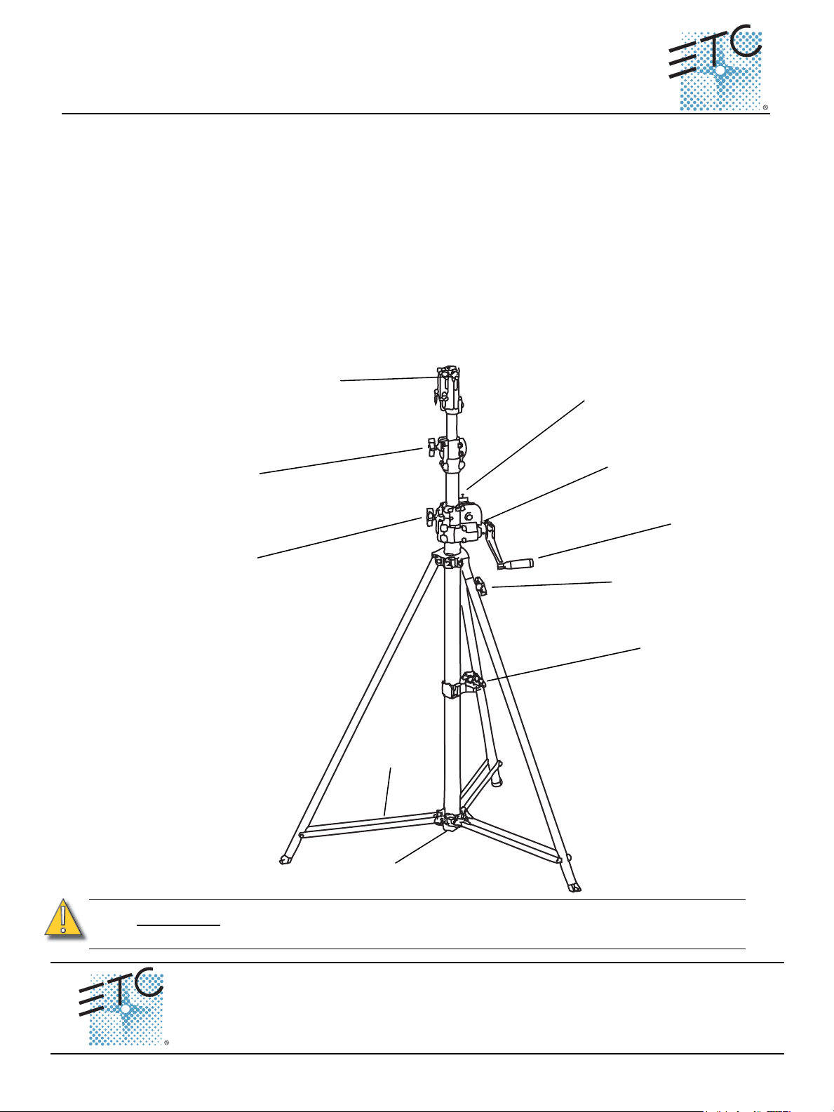
Crank
Handle
Hand
Crank
Lock
Adjustable Leg
Locking Knob
Foot Step
Leg
Support
Top Locking
Knob
Base Locking
Knob
Slide-handle set
screw
Middle Locking
Knob
Slide
Locking Pin
SmartStand
Overview
Your SmartStand is an excellent addition to your Smart Solutions lighting package. Its ease of use,
sturdy composition, and adaptable design offer the perfect solution for your lighting support needs.
Safety Restrictions
• Your SmartStand can support a maximum total load of 30kg (66 lbs).
• Try to balance loads as much as possible when using a crossbar at the top of the SmartStand.
• When using the optional casters, SmartStand should only be set up on a level surface.
• Periodically check to verify that the steel cables inside of the support columns are in good
condition (no fraying, crimping, or rusting).
SmartStand Diagram
Below is a diagram of the SmartStand with its primary parts labeled. Please take time to familiarize
yourself with these terms as they are used consistently throughout this guide.
™
CAUTION:
Before placing any loads on the SmartStand, you must open the tripod stand and
set it firmly in place.
Corporate Headquarters
London, UK
Rome, IT
Holzkirchen, DE
Hong Kong Room 605-606, Tower III Enterprise Square, 9 Sheung Yuet Road, Kowloon Bay, Kowloon, Hong Kong Tel +852 2799 1220 Fax +852 2799 9325
Service:
Web:
7501M2200
Unit 26-28, Victoria Industrial Estate, Victoria Road, London W3 6UU, UK Tel +44 (0)20 8896 1000 Fax +44 (0)20 8896 2000
Via Pieve Torina, 48, 00156 Rome, Italy Tel +39 (06) 32 111 683 Fax +44 (0) 20 8752 8486
Ohmstrasse 3, 83607 Holzkirchen, Germany Tel +49 (80 24) 47 00-0 Fax +49 (80 24) 47 00-3 00
(Americas) service@etcconnect.com
www.etcconnect.com
Rev C Released 2011-07 ETC intends this document to be provided in its entirety.
3031 Pleasant View Road, P.O. Box 620979, Middleton, Wisconsin 53562-0979 USA Tel +608 831 4116 Fax +608 836 1736
Copyright © 2011 ETC. All Rights Reserved. Product information and specifications subject to change.
(UK) service@etceurope.com (DE) techserv-hoki@etcetcconnect.com
(Asia) service@etcasia.com
SmartStand™ Setup Guide Page 1 of 2 Electronic Theatre Controls, Inc.
Page 2
ETC Setup Guide
Setup
Step 1: Loosen the base locking knob and expand the three legs out until the leg supports
slide to the bottom of the center post.
Step 2: Tighten the base locking knob.
Step 3: If your SmartStand has the optional casters installed, engage the locking mechanism
on each of the casters.
Step 4: If you are not using the optional casters, you may use the adjustable leg to
compensate for uneven surfaces by extending the adjustable leg to level the stand
and locking the leg in place with the adjustable leg locking knob
Attach Crossbar
Step 1: If using a SmartBar™ or DumbBar (crossbar), insert the adapter stud bolt through the
center hole in the crossbar device.
Step 2: Screw the stud adapter onto the bolt so that the crossbar device is secured to the stud
adapter. Tighten the bolt.
Step 3: Make sure the SmartStand is lowered to its shortest height.
Step 4: Loosen the slide-handle set screw at the very top of the SmartStand.
Step 5: Insert the bottom of the stud adapter (the end opposite the bolt) into the top of the
SmartStand center post.
Step 6: Tighten the slide-handle set screw so that the screw fits into the bottom notch in the
stud adapter.
SmartStand
Adjust Height
WARNING:
Step 1: Loosen the top and middle locking knobs. If the knobs are locked, the hand crank will
Step 2: Make sure the locking pin at the top of the hand crank assembly is disengaged.
Step 3: Gradually crank the handle to raise or lower the center post to the desired height
Step 4: When raised or lowered sufficiently, engage the locking pin. The locking pin can
Step 5: To secure the top locking knob, straddle the tripod leg closest to the foot step. This will
Step 6: Using your preferred foot, step up using the foot step. Hold the center post for
CAUTION:
Align the foot step so that it is opposite to the crank handle. This will prevent
injury and allow you to access the top locking knob more easily.
Turing the hand crank with the locking knobs engaged may damage your
SmartStand.
be difficult to turn.
(maximum height of 3650mm [12’-0”]).
remain engaged when raising the stand. It must be disengaged to lower it.
provide more support while using the foot step.
balance, and tighten the top locking knob. Foot step maximum load: 90 kg (200 lbs)
When lowering, crank the handle at a gradual controlled rate. Stay aware of the
overhead load and its relation to nearby persons or objects.
The brake shoe controls descent when lowering the SmartStand. You may adjust
tension of the brake shoe to prevent rapid descent of the post. You can do this by
tightening the set screw nearest the hand crank lock with a 5mm Allen wrench.
Secure the Stand
Step 1: Loosen the hand crank lock (turn counter-clockwise).
Step 2: Bend the crank handle down so that it fits between the center post and one tripod leg.
This will help prevent fall-off and/or unauthorized lowering of the stand.
Step 3: Tighten the hand crank lock (turn clockwise) and ensure that all locking knobs have
been tightened.
SmartStand™ Setup Guide Page 2 of 2 Electronic Theatre Controls, Inc.
 Loading...