

Page 1

D00968120A
Stereo Tube Power Amplifier
OWNER’S MANUAL ...............2
MANUEL DU PROPRIÉTAIRE
...15
A-100
Page 2
2
CAUTION
< DO NOT REMOVE THE EXTERNAL CASES OR CABINETS TO
EXPOSE THE ELECTRONICS. NO USER SERVICEABLE PARTS
ARE INSIDE!
< IF YOU ARE EXPERIENCING PROBLEMS WITH THIS PRODUCT,
CONTACT TEAC FOR A SERVICE REFERRAL. DO NOT USE THE
PRODUCT UNTIL IT HAS BEEN REPAIRED.
WARNING: TO PREVENT FIRE OR SHOCK
HAZARD, DO NOT EXPOSE THIS APPLIANCE
TO RAIN OR MOISTURE.
IMPORTANT SAFETY INSTRUCTIONS
1) Read these instructions.
2) Keep these instructions.
3) Heed all warnings.
4) Follow all instructions.
5) Do not use this apparatus near water.
6) Clean only with dry cloth.
7) Do not block any ventilation openings. Install in accordance
with the manufacturer’s instructions.
8) Do not install near any heat sources such as radiators, heat
registers, stoves, or other apparatus (including amplifiers) that
produce heat.
9) Do not defeat the safety purpose of the polarized or
grounding-type plug. A polarized plug has two blades with
one wider than the other. A grounding type plug has two
blades and a third grounding prong. The wide blade or the
third prong are provided for your safety. If the provided plug
does not fit into your outlet, consult an electrician for
replacement of the obsolete outlet.
10) Protect the power cord from being walked on or pinched
particularly at plugs, convenience receptacles, and the point
where they exit from the apparatus.
11) Only use attachments/accessories specified by the
manufacturer.
12) Use only with the cart, stand, tripod,
bracket, or table specified by the
manufacturer, or sold with the apparatus.
When a cart is used, use caution when
moving the cart/apparatus combination to
avoid injury from tip-over.
13) Unplug this apparatus during lightning storms or when
unused for long periods of time.
14) Refer all servicing to qualified service personnel. Servicing is
required when the apparatus has been damaged in any way,
such as power-supply cord or plug is damaged, liquid has
been spilled or objects have fallen into the apparatus, the
apparatus has been exposed to rain or moisture, does not
operate normally, or has been dropped.
CAUTION: TO REDUCE THE RISK OF ELECTRIC SHOCK,
DO NOT REMOVE COVER (OR BACK). NO USERSERVICEABLE PARTS INSIDE. REFER SERVICING TO
QUALIFIED SERVICE PERSONNEL.
The lightning flash with arrowhead symbol, within an
equilateral triangle, is intended to alert the user to the
presence of uninsulated “dangerous voltage” within
the product’s enclosure that may be of sufficient
magnitude to constitute a risk of electric shock to
persons.
The exclamation point within an equilateral triangle is
intended to alert the user to the presence of important
operating and maintenance (servicing) instructions in
the literature accompanying the appliance.
< Do not expose this apparatus to drips or splashes.
< Do not place any objects filled with liquids, such as vases, on
the apparatus.
< Do not install this apparatus in a confined space such as a
book case or similar unit.
< The apparatus draws nominal non-operating power from the
AC outlet even with its POWER switch turned off.
< The apparatus should be located close enough to the AC
outlet so that you can easily reach the power cord plug at any
time.
< An apparatus with Class !construction shall be connected to
an AC outlet with a protective grounding connection.
< Batteries (battery pack or batteries installed) shall not be
exposed to excessive heat such as sunshine, fire or other heat
sources.
< Excessive sound pressure from earphones and headphones
can cause hearing loss.
Page 3
3
ENGLISH
Contents
Thank you for choosing Esoteric. Read this manual
carefully to get the best performance from this unit.
Contents. . . . . . . . . . . . . . . . . . . . . . . . . . . . . . . . . . . . . . . . . . 3
Before use . . . . . . . . . . . . . . . . . . . . . . . . . . . . . . . . . . . . . . . . 4
Speaker connection . . . . . . . . . . . . . . . . . . . . . . . . . . . . . . . . . 5
Connection example (Connecting speakers) . . . . . . . . . . . . . . . 6
Other connections . . . . . . . . . . . . . . . . . . . . . . . . . . . . . . . . . . 8
Connection (Direct). . . . . . . . . . . . . . . . . . . . . . . . . . . . . . . . . 10
Front panel features . . . . . . . . . . . . . . . . . . . . . . . . . . . . . . . . 11
Remote control unit . . . . . . . . . . . . . . . . . . . . . . . . . . . . . . . . 12
Protection circuits . . . . . . . . . . . . . . . . . . . . . . . . . . . . . . . . . . 13
Troubleshooting . . . . . . . . . . . . . . . . . . . . . . . . . . . . . . . . . . . 14
Specifications . . . . . . . . . . . . . . . . . . . . . . . . . . . . . . . . . . . . . 14
CAUTION Regarding Placement
To maintain proper ventilation, be sure to leave a space
around the unit (from the largest outer dimensions including
projections) equal to, or greater than, shown below.
Left and Right Panels: 20 cm (8”)
Rear Panel: 10 cm (4”)
Top Panel: 5 cm (2”)
This equipment has been tested and found to comply with the
limits for a Class B digital device, pursuant to Part 15 of the
FCC Rules. These limits are designed to provide reasonable
protection against harmful interference in a residential
installation. This equipment generates, uses, and can radiate
radio frequency energy and, if not installed and used in
accordance with the instructions, may cause harmful
interference to radio communications. However, there is no
guarantee that interference will not occur in a particular
installation. If this equipment does cause harmful interference
to radio or television reception, which can be determined by
turning the equipment off and on, the user is encouraged to
try to correct the interference by one or more of the following
measures:
• Reorient or relocate the equipment and/or the receiving
antenna.
• Increase the separation between the equipment and
receiver.
• Connect the equipment into an outlet on a circuit different
from that to which the receiver is connected.
• Consult the dealer or an experienced radio/TV technician
for help.
CAUTION
Changes or modifications to this equipments not expressly
approved by TEAC CORPORATION for compliance will void the
user’s warranty.
For U.S.A.
For European customers
Disposal of your old appliance
1. When this crossed-out wheeled bin symbol is
attached to a product it means the product is
covered by the European Directive
2002/96/EC.
2. All electrical and electronic products should be disposed of
separately from the municipal waste stream via designated
collection facilities appointed by the government or the
local authorities.
3. The correct disposal of your old appliance will help prevent
potential negative consequences for the environment and
human health.
4. For more detailed information about disposal of your old
appliance, please contact your city office, waste disposal
service or the shop where you purchased the product.
Page 4
4
What’s in the box
Please confirm that the following accessories are in the box
when you open it.
Power cord x 1
Remote control unit (RC-1156) x 1
Batteries (AA, R6, SUM-3) x 2
Felt pads x 3
Owner’s manual x 1
Warranty card x 1
Read this before operation
< Place the unit in a stable location near the stereo system that
you will use.
< Be careful to avoid injury when moving the unit due to its
weight. Get someone to help you if necessary.
< To protect easily scratched furniture, you may stick the felt
pads supplied with the unit to the feet.
< As the unit may become warm during operation, always leave
sufficient space around the unit for ventilation.
The ventilation holes should not be covered. Make sure there
is at least 20 cm (8”) of space above and at least 5 cm (2”) of
space on each side of the unit. Do NOT place anything such
as CD, CD-R, cassette tape etc. on top of the unit.
< The voltage supplied to the unit should match the voltage as
printed on the rear panel. If you are in any doubt regarding
this matter, consult an electrician.
< Choose the installation location of your unit carefully. Avoid
placing it in direct sunlight or close to a source of heat. Also
avoid locations subject to vibrations and excessive dust, heat,
cold or moisture.
< Do not open the cabinet as this might result in damage to the
circuitry or electrical shock. If a foreign object should get into
the unit, contact your dealer or service company.
< When removing the power plug from the wall outlet, always
pull directly on the plug, never yank the cord.
< Do not attempt to clean the unit with chemical solvents as
this might damage the finish. Use a clean, dry cloth.
< Keep this manual in a safe place for future reference.
< Specially selected tubes are used for this unit. Special
measurement is necessary to adjust the tubes at the time of
replacement. DO NOT replace the tubes by yourself.
Maintenance
If the surface of the unit gets dirty, wipe with a soft cloth or
use diluted neutral cleaning liquid. Be sure to remove any
fluid completely. Do not use thinner, benzine (naphtha) or
alcohol as they may damage the surface of the unit.
Before use
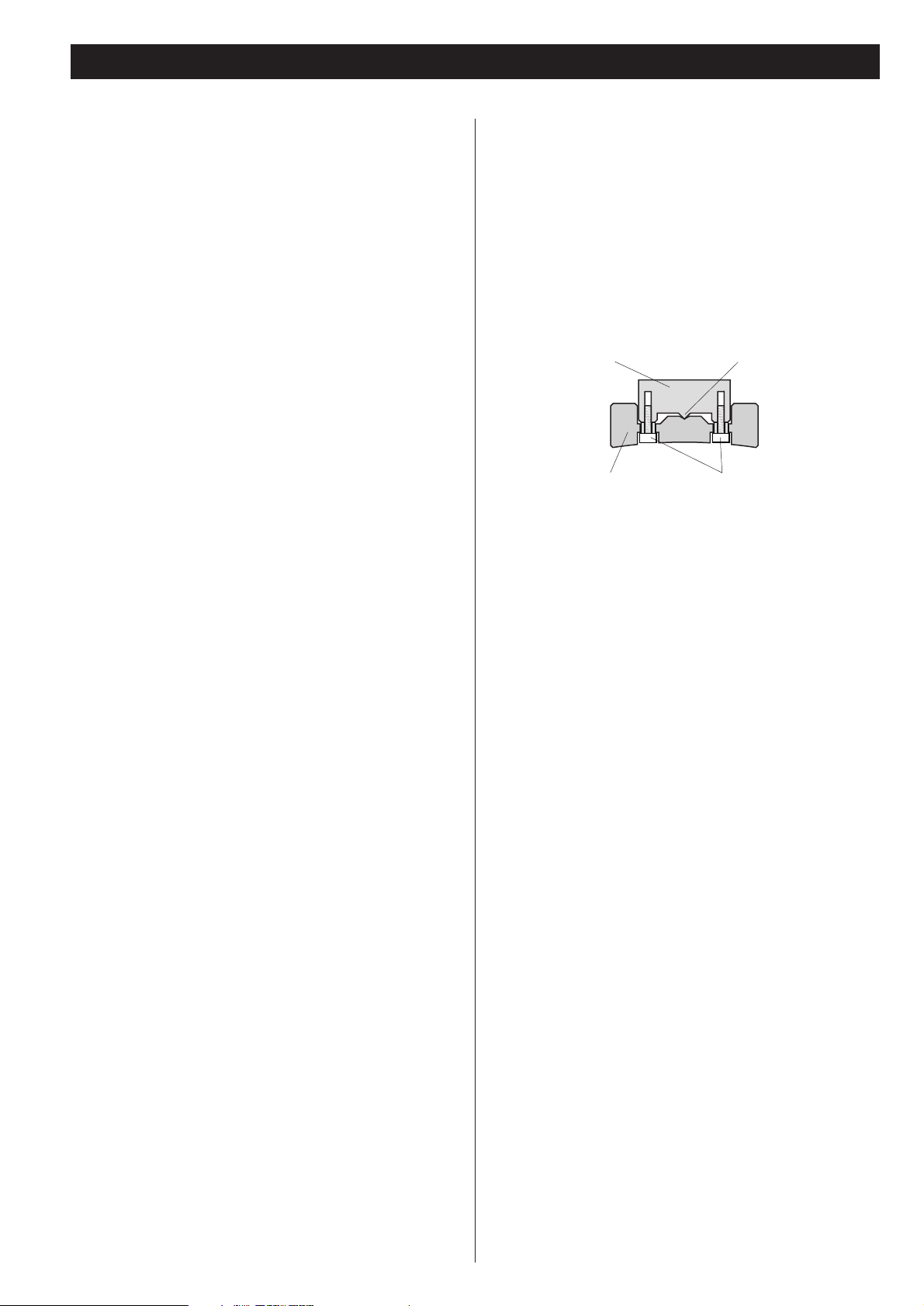
Placement of the unit
High-quality hardened tool stainless-steel is used for the pinpoint feet attached to the bottom of the component.
Although the outer feet may appear loose, the weight of the
unit causes them to become firm and secure. The design
effectively damps and reduces vibration.
< To protect the supporting furniture surface, you may stick the
felt pads supplied with the unit to the bottom of the metal
feet.
Stainless-steel Pin-point foot
Cover foot retaining screwsCover foot
Page 5

ENGLISH
5
About the speaker cable
< Use commercially available speaker cables.
< Use the same length of speaker cables for the left and right
speakers. Minimizing excess speaker cable length may allow
an improvement in sound quality.
Connection method
Connect the unit’s + terminal to the speaker’s + terminal,
and the unit’s – terminal to the speaker’s – terminal.
< This unit is equipped with WBT's speaker terminals. Turn the
terminal cap counterclockwise to loosen and clockwise to
tighten.
< The metal portions of the two separate wires (Positive and
negative), should not touch or an electrical short can occur.
Shorted wires can create a fire hazard or induce a failure in
your equipment.
< Generally, the + side of the speaker cable is marked to make
it distinguishable from the – side of the cable. Connect this
marked side to the + terminal and the unmarked side to the
black – terminal.
CAUTION:
< Switch off the power to all equipment before making
connection.
< Read the instructions of each component you intend to use
with this unit.
About the speaker terminal
When your speaker cable is bare wire:
Twist the strands of the stripped wires tightly together.
< The thickness of wires should be less than 4 mm (1/8”).
When your speaker cable has spades:
Loosen the terminal cap and insert the spade into the
terminal. Then turn the terminal cap clockwise to tighten it.
< The inside diameter of spades should be 8 mm or more.
Connection using speaker cables with
banana plugs
Tighten the terminal cap and insert a banana plug.
For European customers
In accordance with European safety regulations, it is not
possible to connect banana plugs into the speaker terminals
on European models.
The holes into which banana plugs are inserted have been
covered with black caps. Connect the speakers using spades
or bare wires.
If the black caps become separated from the terminals, return
them to their original position.
Speaker connection
Page 6

6
When 4$$speakers are connected
When 6
$$
, 8$$or 16$$speakers are connected
Q
Note:
< Connect to a terminal which corresponds to the impedance of the speaker.
To connect 4
Ω
speakers to the unit, connect the unit’s 4Ωterminals to the speaker’s + terminals.
To connect the speakers of 6
Ω
, 8Ω, 16Ωor higher, connect the unit’s 8Ωterminals to the speaker’s + terminals.
Connect the unit’s COM terminal to the speaker’s – terminal.
Connection example (Connecting speakers)
Right speaker Left speaker
Right speaker Left speaker
Page 7

ENGLISH
7
When biwiring 4$$speakers
When biwiring 6
$$
, 8$$or 16$$speakers
Q
Note:
< To biwire this unit and speaker, use either one of the 8Ωterminal or 4Ωterminal.
Do not connect the 4
Ω
terminal to a tweeter, 8Ωterminal to a woofer, etc.
Right speaker Left speaker
Right speaker Left speaker
Page 8

8
Other connections
AUDIO OUT
RL
LINE OUT
RL
AUDIO OUT
RL
AUDIO OUT
RL
A
B
C
D
EF
Page 9

9
ENGLISH
Analog audio input terminals [LINE IN]
Used for the input of analog 2-channel audio signals.
Connect these terminals to a Super Audio CD player
(Example: SA-10, X-01SE, etc), DVD player, cassette tape
deck, tuner, etc. using commercially available XLR or RCA
audio cables. Connect the unit’s R terminal to the player’s R
terminal, and the unit’s L terminal to the player’s L terminal.
To use line input, set the LINE IN/DIRECT IN switch to “LINE
IN”. Select an input with the INPUT button on the front
panel and adjust the volume with the VOLUME control
knob. The remote control can also be used in this “LINE IN”
(Integrated amplifier), setting.
< Push in the XLR balanced plug until the lever is locked. To
remove the balance plug, hold the lever and pull out the
plug.
< XLR connector pin assignment:
BIAS switch
It is possible to select the bias current for the KT-88 output
tube with this switch.
A bias current is a current that continues to flow to a tube
when there is no input signal. Depending on preset values, a
bias current can cause distortions in sound quality. The
standard setting is B. The bias current will decrease when set
to A, and depending on the compatibility between the tube
and the system it is connected to, sound quality may
become slightly more delicate. There is a tendency to use
this setting when playing classical music.
Depending on the accompanying machine, changes can be
difficult to detect on the A setting. Please set to B if you
cannot detect audible changes on the A setting.
Volume control motor cover
This covers the motor that drives the volume control. This is
not an operational control. Do not remove this cover.
C
B
A
Fuse holder
The fuse used in this unit is 250V5A slow blow. Do not use
other fuses.
< Unplug the power cord when you replace the fuse.
< If the fuse blows out even if you replace it, consult your
dealer.
AC inlet
Use only the supplied Esoteric power cord. Use of other
power cords may result in fire or electric shock. Unplug the
power cord when you are not going to use the unit for an
extended period of time.
SIGNAL GND connection
Use a commercially available PVC-covered cord to connect
the signal ground terminal on the unit to the player’s signal
ground.
< Note that this is NOT an electrical safety ground (earth).
F
E
D
Page 10

10
Connection (Direct)
When using an external preamplifier, use the DIRECT terminal,
and set the LINE IN/DIRECT IN switch to “DIRECT IN”.
(This setting allows you to use this device as a direct power
amplifier bypassing it‘s pre-amplifier stage.)
< Your remote control cannot be used in this setting.
AUDIO OUT
RL
G
H
DIRECT terminal
Connect to an external preamplifier’s output port using an
RCA audio cable.
LINE IN/DIRECT IN switch
This switch changes between LINE IN and DIRECT IN.
< The “LINE IN” setting allows this amplifier to operate as an
integrated amplifier.
H
G
Page 11

ENGLISH
11
Front panel features
BA
DE
C
Note: The following 3 controls will only work in the “LINE IN”
(Integrated amplifier) mode.
INPUT
Select the terminal to which the equipment to play is
connected.
MUTING
Use this button to mute the sound.
VOLUME
Turn this knob to adjust the volume.
C
B
A
When the LINE IN/DIRECT IN switch on the rear panel is set to “DIRECT IN”, the front panel buttons will not work except for the
POWER switch. This is normal for DIRECT mode operation.
POWER
Use this switch to turn the unit on and off.
The indicator lights in red once when you turn on the unit.
Then the indicator lights in blue after 1 minute and audio is
output. The indicator lights in red also when the protection
circuit is operating (page 14).
< Once the unit is turned off, wait for at least 5 minutes to turn
it on again in order to protect the tubes.
Remote control sensor
Receives signals from the remote control unit. Point the
remote control unit at this sensor when operating the remote
control unit (This works in the rear panel “LINE IN” setting
only).
E
D
Page 12

12
Remote control unit
Notes on use
< Point the remote control unit at the amplifier’s remote sensor
within seven meters (23 feet) of the amplifier. There should
not be any obstacles between the amplifier and the remote
control unit.
< Do not allow direct sun or other light to shine on the remote
sensor part of the amplifier. This may cause the remote
control unit to work incorrectly.
< Note that other units with remote controls may operate
incorrectly because of infrared light “overspill” when you
operate this remote control unit.
< To use the remote control unit, set the LINE IN/DIRECT IN
switch on the rear panel to “LINE IN”.
Remote control sensor
The remote control unit RC-1156 is used in common with
Esoteric digital amplifiers and certain CD/DVD players (other than
P-01/D-01).
When configured as an integrated amplifier, you can use the
following buttons for A-100:
VOLUME, INPUT, MUTING
< The remote control unit is available only when the LINE
IN/DIRECT IN switch on the rear panel is set to “LINE IN”.
VOLUME
Use these buttons to adjust the volume.
INPUT
Use these buttons to select an input.
MUTING
Use this button to mute the sound. Note that A, B and C
above only operate in the “LINE IN” (Integrated amp), mode.
C
B
A
A
B
C
Page 13

ENGLISH
13
How to insert the batteries
Remove the cover of the remote control unit with a
screwdriver. After checking the polarity (
+/_) of two AA
batteries, insert the batteries, replace the cover and replace
the screws.
< Take care not to pinch cables with the battery case.
Battery Replacement
If the distance required between the remote control unit and
main unit decreases, the batteries are exhausted. In this case
replace the batteries with new ones.
Precautions concerning batteries
< Be sure to insert the batteries with correct positive “+” and
negative “
_” polarities.
< Use batteries of the same type. Never use different types of
batteries together.
< Rechargeable or non-rechargeable batteries can be used but
not mixed together. Refer to the precautions on their labels.
< When the remote control unit is not to be used for a long
time (more than a month), remove the batteries from the
remote control unit to prevent them from leaking. If they
leak, wipe away the liquid inside the battery compartment
and replace the batteries with new ones.
< Do not heat or disassemble batteries and never dispose of old
batteries by throwing them in a fire.
Protection circuits
In order to protect the output level to the tubes, this unit is
equipped with a protection circuit to detect overcurrents.
When an overcurrent is detected, the protection circuit will shut
off the output tube’s current and continue to do so until the
power is switched off.
Presumably, the main cause of a protection circuit activating is
when the speaker cord connected to the output port short
circuits. The protection circuit may also activate when it is
connected to a speaker with lower impedance than allowed,
resulting in a large input that creates an overcurrent.
When the protection circuit has activated, look at the output
port and the speaker it is connected to and remove the cause of
the overcurrent. Following this action, wait 5 minutes and then
turn the power back on. Should the protection circuit continue
to activate even after removing the cause of the overcurrent,
please contact your dealer or contact TEAC for service
instructions.
When a large signal is input while a protection circuit is
functioning, a very slight electrical noise from the current may be
heard. This is not cause for alarm. This is the circuit maintaining
its protection of the output tubes.
Page 14

14
Specifications
General
Power supply
Europe model. . . . . . . . . . . . . . . . . . . . . AC 230 V, 50 Hz
U.S.A./Canada model . . . . . . . . . . . . . . . AC 120 V, 60 Hz
Power consumption . . . . . . . . . . . . . . . . . . . . . . . . . . 200 W
Weight . . . . . . . . . . . . . . . . . . . . . . . . . . . . 40 kg (88 4/5 lb)
External dimensions (W x H x D)
382 x 252 x 486 mm (15 1/16” x 9 7/8” x 19 1/16”)
Operating temperature . . . . . . . . . . . . . . . . . . +10˚C - +30˚C
Operating humidity . . . . . . . . 5% to 85% (no condensation)
Storage temperature . . . . . . . . . . . . . . . . . . . . –20˚C - +55˚C
Amplifier Section
Maximum useful output power . . . . . . . . . . . . 45 W + 45 W
(1 kHz, 8 ohms/4 ohms, JEITA)
Total Harmonic Distortion . . . 0.1 % (at 1 W, 1 kHz, 8 ohms)
Frequency Response . . . . . . . . . . . . . . . . . . . . 20 Hz to 60 kHz
(at 1 W, 8 ohms, +1/–3 dB)
Signal-to-Noise Ratio . . . . . . . . . . . . more than 98 dB (JEITA)
Input Sensitivity (maximum output at maximum volume)
400 mVrms/45W (8
Ω
)
Input impedance. . . . . . . . . LINE IN: 10 k
Ω
, DIRECT IN: 1 M
Ω
Tube Section
First stage . . . . . . . . . . . . . . . . . . . . . . . . . . . . . . . 12AT7 x 2
Drive stage . . . . . . . . . . . . . . . . . . . . . . . . . . . . . . 12AU7 x 4
Bottom stage. . . . . . . . . . . . . . . . . . . . . . . . . . . . . . KT88 x 4
Accessories
Power cord x 1
Remote control unit (RC-1156) x 1
Batteries (AA, R6, SUM-3) x 2
Felt pads x 3
Owner’s manual x 1
Warranty card x 1
• Design and specifications are subject to change without
notice.
• Weight and dimensions are approximate.
• Illustrations may differ slightly from production models.
Troubleshooting
If you experience any problem with this unit, please take the
time to look through this chart and see if you can solve the
problem yourself before you call your dealer.
General
No power
e Check the connection to the AC power supply. Check and
make sure the AC source is not a switched outlet and that,
if it is, the switch is turned on.
e Insert the power cord into the AC inlet of this unit.
Remote control doesn’t work.
e Press the POWER switch of the main unit to turn it on (page
13).
e If the batteries are dead, change the batteries (page 12).
e Use remote control unit within the range (7m/23ft) and
point at the front panel (page 12).
e Set the LINE IN/DIRECT IN switch on the rear panel to “LINE
IN” (page 10). The remote control for this amplifier will only
work in the “LINE IN” (Integrated amp), mode.
There is no sound or only a very low-level sound is heard.
e Press the POWER switch to turn on the unit, your external
pre-amplifier (If any), and disc player, etc.
e Make sure a signal is output from a pre-amplifier or a player,
etc.
e Check if the pre-amplifier, speakers and source components
are secure connected.
e Select input setting of the pre-amplifier correctly.
e Adjust the pre-amplifier volume.
e The protection circuit is in operation when the color of the
indicator ring of the POWER switch changes from blue to
red. Turn off the unit immediately if this indicator is red and
solve the cause of problem.
e The speaker cord may be shorted out. Check your speaker
connections.
Unstable sound.
e Speaker polarity (+/_) is reversed. Check all speakers for
correct polarity.
If normal operation cannot be obtained, unplug the power
cord from the outlet, wait about 60 seconds and plug it
again. This resets the internal micro-computer which can
be disturbed during electrical storms, power interruptions,
etc.
Page 15

382mm 486mm
252mm
15
Page 16

1207.MA-1313A
This appliance has a serial number located on the rear panel. Please record
the model number and serial number and retain them for your records.
Model number Serial number
TEAC ESOTERIC COMPANY
1-47 Ochiai, Tama-shi, Tokyo 206-8530, Japan Fax: (042) 356-9240 e-mail: eso-os@tec.teac.co.jp
TEAC AMERICA, INC. 7733 Telegraph Road, Montebello, California 90640 Phone: (323) 726-0303 e-mail: esoteric_info@teac.com
TEAC CANADA LTD. 5939 Wallace Street, Mississauga, Ontario L4Z 1Z8, Canada Phone: (905) 890-8008
TEAC MEXICO, S.A. De C.V Campesinos N°184, Colonia Granjas Esmeralda, Delegacion Iztapalapa, CP 09810, México DF Phone: (525) 581-5500
TEAC UK LIMITED Unit 19 & 20, The Courtyards, Hatters Lane, Watford, Hertfordshire, WD18 8TE, U.K. Phone: (0845) 130-2511
TEAC EUROPE GmbH Bahnstrasse 12, 65205 Wiesbaden-Erbenheim, Germany Phone: 0611-71580
 Loading...