

Page 1
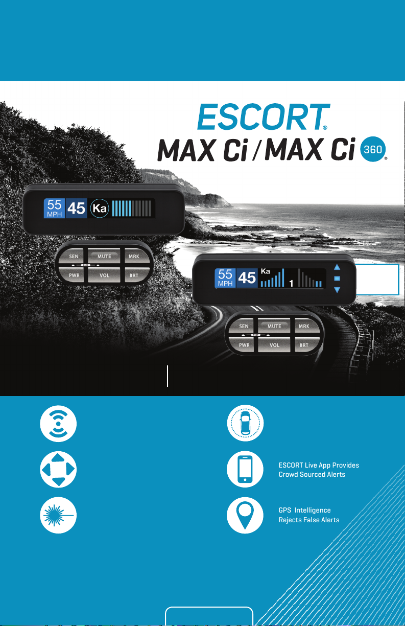
The World’s Most Advanced Detection System
360°
Alerts
MAX Ci / MAX Ci 360
Dual Antenna Front and Rear
Protection (MAX Ci 360)
360° Directional Alert
Arrows (MAX Ci 360)
Laser Shifters Provide
Speed of Light Protection
The most powerful & complete
protection available
True Stealth Operation Lets
You Drive 100% Undetected
ESCORT Live App Provides
Crowd Sourced Alerts
GPS Intelligence
Rejects False Alerts
Installation Manual
Page 2
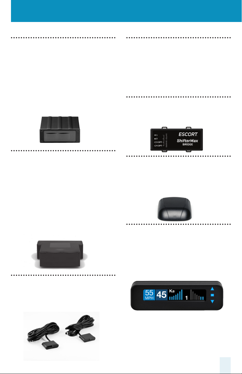
ESCORT MAX Ci Components
Front Radar Receiver
• Weatherproof radar receiver
• Two universal mounting brackets with stainless
steel hardware
• Built-in 3-foot cable with waterproof
connector
• 13-foot cable with waterproof connector and
inline grommet
• 12 nylon wire ties to secure cable
Rear Radar Receiver* (optional)
• Weatherproof radar receiver
• Two universal mounting brackets with stainless
steel hardware
• Built-in 2.9 foot cable with waterproof connector
• 13-foot cable with waterproof connector and
inline grommet
• 12-foot extension cable with waterproof
connectors
• 12 nylon wire ties to secure cable
Rear Laser ShifterMax Sensors*
(optional)
• Twin weatherproof sensors
• 6-foot cables with waterproof connectors
• 2 x 20-foot extension cables
• Mounting hardware
ShifterMax Bridge Box
• Weatherproof Bridge Box is used to connect
ShifterMax Sensors to main Interface
GPS Antenna
• Weatherproof magnetically mounted GPS
Antenna
• 30-foot cable with modular connector
Display Module
• Display mounts easily to instrument pod,
dashboard, or console
• Two bezels provided for optional in-dash
mounting
• Adhesive pads provided for secure mounting
Front Laser ShifterMax Sensors
• Twin weatherproof sensors
• 6-foot cables with waterproof connectors
• Mounting hardware and bubble level
* Included with ESCORT MAX Ci 360
2
Page 3
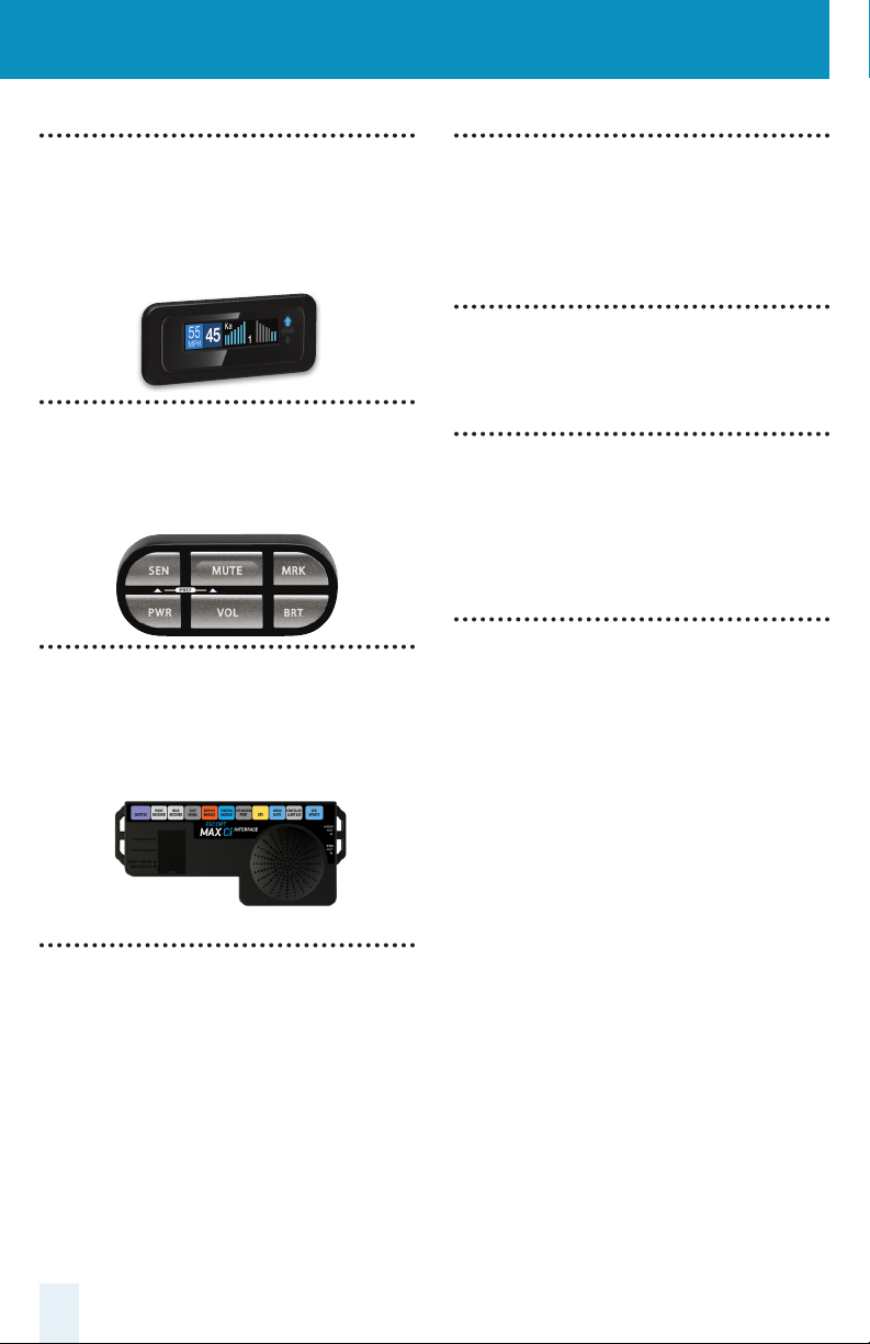
In-dash Display Bezels
• For a factory-installed look, use either the black or
platinum in-dash bezel for easy mounting to
instrument pod, dashboard, or console.
• Integrated adhesive backing for secure mounting
Control Module
• Controller mounts easily to instrument pod,
dashboard, or console
• Adhesive pads provided for secure mounting
Interface
• Central module connects to switched 12-volt
power and ground
• All components plug directly in using modular
connections
Radio Mute Cable
• 6-foot cable connects to compatible vehicle
audio systems and automatically mutes the
audio during alerts
Download Data Cable
• Provides access to update data via the Internet
Documentation
• Comprehensive Owner’s Manual
• Installation guide
Built-in Diagnostics
• Confirms all components are operational
Concealed Alert Indicator
• Multi-color indicator is:
• Solid green when power is ON
Blinking red when receiving a front alert
•
Blinking blue when receiving a rear alert
•
(ESCORT MAX Ci 360 only)
• 6-foot cable with modular connector
• Bezel provided mounts easily to instrument pod,
dashboard, or console
3
Page 4
Important Notes
Installation Warnings
1 It is recommended that you have a
professional install your new ESCORT MAX Ci .
Installation of this system requires experience
and expertise in automotive electronics. If you
are unfamiliar with automotive electronics, car
audio specialists and many car dealers can
install your ESCORT MAX Ci for you.
2 Attempting to install this product without
expertise in automotive electronics installation
can cause personal injury or damage to your
vehicle.
3 If your vehicle is damaged during
installation its safety systems may be
compromised, which could cause personal
injury or property damage.
4 Improper installation may void ESCORT
MAX CI’s warranty.
Performance Warning
To get the best performance possible, the
mounting location of the radar receiver is
critical. Although radar signals will pass
through some types of plastic, mounting
the radar receiver so that it has a clear
“view” of the road will ensure maximum
warning.
Since Laser signals will not pass through
objects, including most plastics, it is critical
that the Laser Shifters are mounted
perfectly level and have an unobstructed
“view” of the road.
E Read This First
Please read these instructions in their entirety
before starting your installation.
For the easiest, trouble-free installation, install
the interface first and wire it to a 12-volt
switched circuit.
Then, before installing the other components,
plug all of them into the interface and power
up the unit to confirm proper operation.
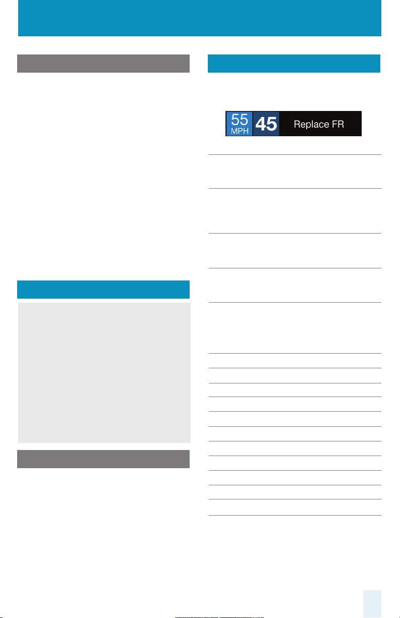
Error Codes
Below is a list of error codes which are shown
in error messages. The codes help diagnose
the cause of the error.
Error
Replace A critical issue has been reported
requiring component to be
replaced or repaired.
Check Connections and wiring of
component should be checked. If
problem persists there may be an
issue with component.
High Temp Component is too hot. Mounting
it in a cooler location may be
necessary.
Hi Volt Power supply voltage is too high.
Voltage must be between 10.5 –
16 V DC.
Lo Volt Power supply voltage is too low.
Voltage must be between 10.5 –
16 V DC.
Component
IF Interface
FR Front Radar Receiver
RR Rear Radar Receiver
GR GPS Receiver
SB Shifter Bridge Box
S1 Shifter Sensor 1
S2 Shifter Sensor 2
S3 Shifter Sensor 3
S4 Shifter Sensor 4
S5 Shifter Sensor 5
S6 Shifter Sensor 6
For information about accessing the error code
log, visit the “User Manuals” section of the
EscortRadar.com website.
4
Page 5

Installation Instructions
Installation Tips
While following the steps throughout this
manual, please refer to the following
recommendations for a professional, troublefree installation:
1 Determine the best location for the radar
receiver. The best location is typically under
the bumper, or inside the front grill of the
vehicle. For the best radar performance, install
the radar receiver horizontally, with a clear
“view” of the road.
2 Entry points into the interior may be located
behind the plastic liner in the wheel well, fuse
box, or unused grommets.
3 There are often many existing entry points
at the rear of the vehicle as well:
• Gaskets behind license plates, around
illumination lamps, and near trunk lid hinges.
• Tail light wiring gaskets are often easily
accessible and large enough to add cables.
4 If there are no suitable openings, it will be
necessary to drill a hole through the firewall:
a. Thoroughly investigate all locations
before drilling any holes! Ensure no wires,
hoses, or other vehicle components will be
damaged.
b. On vehicles with automatic transmissions,
there is often a location for mounting a
clutch pedal. This location is typically an
ideal location to drill.
c. Before drilling, cover the surface being
drilled with masking tape to prevent
damage to the anti-corrosion coating in the
event the drill bit slips.
d. Drill a 13/32" or 7/16" hole.
5 When pulling the inline grommet to the
entry point, apply rubbing alcohol to a section
of the cable to reduce friction and quickly pull
the grommet along the length.
6 The cables of units mounted at the rear of
the vehicle can generally be routed through
the trunk compartment and concealed under
trim panels quite easily. If necessary, the cables
can also be routed under the vehicle and
through an opening in the firewall. Be sure to
secure cables away from moving parts and hot
surfaces.
7 A quality crimper for modular connectors
can be used to cut cables to length and replace
the connector. Removing the connectors may
also make it easier to enter the vehicle’s interior
through existing openings.
Note:
• Only an exact replacement for the
standard connector can be used. Do not
attempt to cut the wires unless the proper
connector and crimping tools are available.
• Connectors cannot be reused.
• Do not cut the cable too short! Provide
enough cable to route to the Interface and
add a couple extra feet to ease installation
• Install the new connector such that its
locking tab is on the same side as the color
coded stripe on the cable.
• Do not attempt to cut the cable and splice
the wires together.
8 When drilling or cutting interior trim panels
(for instance, when installing the Concealed
Installation Alert Indicator or the optional
Display Bezel), first cover the surface of the
panel with masking tape to prevent accidental
scratches.
5
Page 6

A B
Interface
1 Install the Interface under the dash using
supplied zip-ties.
Note:
Do not mount Interface inside vehicle’s
engine compartment!
2 Connect black wire (-) to ground, and
red-striped wire (+) to a switched 12-volt
supply. (If ESCORT MAX Ci is left in the “on”
position, it will automatically power on and off
with the ignition).
3 Front Radar Receiver, ShifterMax Bridge Box,
Display and Control Modules, GPS Antenna,
Concealed Alert LED, Radio Mute Cable, and
optional Rear Radar Receiver* all plug into the
Interface.
4 It is recommended that after the Interface is
installed and connected to power, all other
components are plugged in and tested for
proper operation before completing the
installation.
IMPORTANT! When using optional Rear
ShifterMax sensors* ensure DIP switches 3
and 4 are moved down to the REAR
SHIFTER position. See the Interface
illustration on pg 9.
* included with ESCORT MAX Ci 360
Front Radar Receiver White Stripe
1 Determine the best location for the Radar
Receiver. The best location is typically under
the bumper or inside the front grille of the
vehicle. For the best radar performance install
the Radar Receiver flat, horizontally, not on its
side.
2
The included adjustable mounting clamps
can be used to easily secure the Radar Receiver
to the slats in a grille or the edge of an opening.
• To tighten clamp jaws, insert a 9/64” hex
key into the screw on the front of each
clamp and turn clockwise.
• To adjust the angle and remove the clamps,
use the screw on the side of each clamp.
3
Alternatively, you can use the supplied
U-shaped and right-angle mounting brackets.
Mark the mounting location and drill pilot holes
in the vehicle if necessary. It is recommended
that the Radar Receiver is secured to the
brackets first, and then mount the Receiver and
brackets assembly to the vehicle.
4 Slide the heatshrink onto the Radar Receiver
cable then plug into the harness and route the
cable toward the interior of the vehicle. Shrink
the heatshrink onto the inline connector and
secure the cable with zip-ties. Although
waterproof, it is best to locate the inline
connector in a dry area protected from moving
parts, road debris, and hot surfaces such as the
radiator and radiator hoses.
6
Page 7

Front Radar Receiver (Continued)
5 Find a suitable entry point into the vehicle’s
interior. Refer to the Installation Tips section.
6 Feed the harness into the vehicle’s interior
and to the Interface. Plug into the connector
labeled “Front Receiver.”
7 If entering through a drilled hole, pull the
grommet on the harness until the end sticks
through the hole. From inside the vehicle, pull
grommet through until it seals against the
outer surface.
C
ShifterMax Bridge Box
D
Front Laser ShifterMax
Sensors
Positioning Sensors
Install each sensor halfway between the side
and the center of the vehicle.
For optimal performance sensors need to be
completely unobstructed, not behind a grille,
level and facing straight forward (rearward if
installing optional rear sensors*). Make sure
that each sensor is parallel with the road
(using supplied bubble level).
1 The Bridge Box is weatherproof. To limit the
number of cables routed through the firewall,
we recommend installing the Bridge Box
inside of the engine compartment.
2 Slide the included heatshrink onto the
Bridge Box Interface cable then plug into the
cable extending from the Bridge Box labeled
“Interface” and route the cable toward the
interior of the vehicle. Shrink the heatshrink
onto the inline connector and secure the cable
with zip-ties. Although waterproof, it is best to
locate the inline connector in a dry area
protected from moving parts, road debris, and
hot surfaces such as the radiator and radiator
hoses.
7
Note:
Vehicle must be positioned on a flat surface
in order to position sensors parallel with the
road. Make sure that sensors have an
unobstructed “view” of the road so the unit
can function properly. Do not install sensors
behind a solid surface, which would block
laser transmission/reception.
Page 8

Installation Schematic Overview
Letter References For Components (Color Coded Connections To Interface)
A Interface
B Front Radar Receiver (White Stripe)
C Front ShifterMax Sensors (plug into ports 1 & 2 on ShifterMax Bridge Box)
D ShifterMax Bridge Box (plugs into Interface using supplied cable with no
stripe or shrink)
E GPS Antenna (Yellow Shrink)
F Display Module (Orange Shrink)
G Control Module (Blue Shrink)
H Concealed Alert Indicator (Gray Shrink)
I Rear Radar Receiver (optional, included with ESCORT MAX Ci 360)
J Rear ShifterMax Sensors (optional, included with ESCORT MAX Ci 360)
B
C
D
D
ShifterMax Bridge Box
1 The Bridge Box is weatherproof so
C
it can be installed in the engine
compartment or under the dash.
2 Connect Front ShifterMax Sensors
to ports 1 and 2 of the Bridge Box.
3 Connect Rear ShifterMax Sensors
to ports 3 and 4 of the Bridge Box.
4 The Bridge Box connects to the
Interface using the supplied cable
with a 6 pin modular plug on one
end and a round shifter plug on
the other end.
A
H
G
F
88
Page 9

D
I F G HE
B
Optional Components
(Included with ESCORT MAX Ci 360)
J
E
I
J
99
Page 10

Front Laser ShifterMax
Sensors (Continued)
1 Snap mounting bracket onto sensor and
install the included bolts but do not tighten
them. If the bolts do not thread into the sensor
then you have the bracket on backwards.
2 Apply the double sided tape to the
underside of the sensor’s mounting bracket.
Check front alignment and mount the sensor
to a solid surface of the vehicle.
3 Use the supplied bubble level to ensure the
sensor is parallel to the road and tighten the
sensor’s mounting bracket bolts.
4 Repeat for additional sensor(s).
E
GPS Antenna Yellow Shrink
1 Determine the best location for the GPS
antenna. The GPS Antenna requires a clear
view of the sky. The magnetic base can be used
on most vehicles to mount to the roof of the
car or the trunk lid. It can also be mounted to
the dashboard or rear deck using double-sided
tape.
2 Mount the GPS Antenna, being sure that
roof racks or other obstructions do not block
its view of the GPS satellites.
Securing Connectors with Shrink Tube
Once you’ve installed all components properly
and tested to ensure all parts are working
properly, use cable ties to fasten sensor cables
to a solid surface, keeping them away from
heat and any moving parts. It is advisable to
use the supplied heatshrink tubes to protect
connectors against water, moisture, dust, etc.
IMPORTANTLY the ShifterMax sensors are
shipped in “receive only” mode. Shifting
must be enabled in the bands settings. See
the Preferences section of the Owner’s
Manual.
Additional ShifterMax Sensors
• ESCORT MAX CI users wanting to add rear
sensors, two (2) additional ShifterMax
Sensors with included hardware are sold
separately.
3 Locate a suitable entry point into the
vehicle. Refer to the Installation Tips section for
locating a suitable entry point.
4 Route the cable through the entry point and
secure along its path. If mounting near the
front or rear window, it is usually possible to
tuck the cable under the gasket surrounding
the glass.
5 Once inside the vehicle’s interior, route the
cable to the Interface and plug into the
connector labeled “GPS.”
6 Secure and conceal the cable under interior
trim panels.
10
Page 11

F
Display Module Orange Shrink
Display Bezel Mounting
1 Determine the best location for the Display
Module. If installed by a professional, the
customer should be consulted. An optimal
location is clearly visible from the driver’s
position and does not take a driver’s eyes off
the road for more than a moment.
2 Clean the mounting surface thoroughly.
3 Mount the Display using the pre-applied
adhesive.
4 Route the cable to the Interface and plug
into the connector labeled “Display Module.”
5 Secure and conceal the cable under trim
panels.
1 The supplied display bezel can be used to
mount the Display permanently in the dash or
console.
2 Determine the best location for the Display
Module. If installed by a professional, the
customer should be consulted. A flat, plastic
surface with no obstructions behind it is best
for this type of mounting.
3 Cover the mounting surface with masking
tape to prevent accidental scratches.
4 Using the supplied hole template, mark the
location.
5 Ensure there are no hidden cables, brackets,
or other components behind the location, and
that there is adequate clearance behind the
panel. The Display will protrude into the dash
or console by 1/2".
6 Very carefully cut the hole in the mounting
surface.
7 Feed the display module cable through the
bezel and the opening in the dash then route it
to the interface.
11
8 Remove the masking tape protecting the
trim panel.
9 Clean the mounting surface thoroughly.
10 Apply the double-sided adhesive tape to
the display bezel.
11 Mount the Display Module using the bezel
adhesive.
12 Plug the connector into the Interface
connector labeled “Display Module.”
13 Secure and conceal the cable under trim
panels.
Page 12

G
Control Module Blue Shrink
1 Determine the best location for the Control
Module. If installed by a professional, the
customer should be consulted. An optimal
location is easily visible and accessible from
the driver’s position, and does not interfere
with normal driving. Avoid locations that
require reaching through or around the
steering wheel.
H
Concealed Alert
Indicator Gray Shrink
1 Determine the best location for the Alert
Indicator. If installed by a professional, the
customer should be consulted. An optimal
location is clearly visible from the driver’s
position and does not take a driver’s eyes off
the road for more than a moment.
2 Clean the mounting surface thoroughly.
3 Mount the Control using the pre-applied
adhesive.
4 Route the cable to the Interface and plug
into the connector labeled “Control Module.”
5 Secure and conceal the cable under trim
panels.
2 Ensure there are no hidden cables, brackets,
or other components behind the mounting
location, and that there is adequate clearance
behind the panel.
3 Cover the mounting surface with masking
tape to prevent accidental scratches.
4 Carefully mark the location and drill a 1/4"
hole through the mounting panel.
5 Remove the masking tape protecting the
trim panel.
6 From the front side, snap one of the panel
bezels provided into the hole.
7 Snap the Alert Indicator into the panel bezel
from the back side.
8 Route the cable to the Interface and plug
into the connector labeled “Concealed Alert
LED.”
9 Secure and conceal the cable under trim
panels.
12
Page 13

I
Rear Radar Receiver* optional
1 Follow the same installation instructions as
for the Front Radar Receiver but with the
receiver’s arrow oriented to point out the rear
of the vehcle.
After all components are installed correctly:
Operation Test
1 Turn ESCORT MAX Ci on by turning on the
vehicle’s ignition and, if necessary, press the
power button on the Control Module.
2 Entry points to the vehicle’s interior may be
available behind the license plate or lights.
J
Rear Laser ShifterMax
Sensors* optional
IMPORTANT! When using optional Rear
ShifterMax sensors* ensure DIP switches 3
and 4 are moved down to the REAR
SHIFTER position. See the Interface
illustration on pg 9.
1 Follow the same installation instructions as
for the Front Laser ShifterMax Sensors but with
the sensors oriented to point out the rear of
the vehicle.
2 Entry points to the vehicle’s interior may be
available behind the license plate or lights.
Radio Mute Cable
1 The radio mute cable (included) allows the
detector to be connected to compatible audio
systems with a “Radio Mute” wire or connector.
Once connected, the audio level of the stereo
is reduced automatically during an alert.
2 ESCORT MAX Ci will cycle through a startup
sequence.
3 If any error messages come up, see the
Owner’s Manual troubleshooting section for
suggested solutions.
USB Update Cable
The USB Update cable allows updating the
ESCORT MAX Ci’s DEFENDER database and
firmware. ESCORT MAX Ci’s red light and speed
camera DEFENDER database is easily updated
using our exclusive detector software tools
found on our web site. Firmware, or the
operating software for the detector, can also
be updated using these tools.
In order to have access to these updates,
please register your ESCORT MAX Ci at www.
EscortRadar.com. Once registered, you will
receive email notifications when updates are
available.
2 Please refer to your audio system’s manual
for proper connection to your audio system.
* included with ESCORT MAX Ci 360
13
If you have any questions, please call or visit
our website. One of trained radar specialists
will be happy to assist you.
800-543-1608 / EscortRadar.com
Page 14

360°
Alerts
The World’s Most Advanced Detection System
The most powerful & complete
protection available
MAX Ci / MAX Ci 360
Dual Antenna Front and Rear
Protection (MAX Ci 360)
True Stealth Operation Lets
You Drive 100% Undetected
360° Directional Alert
Arrows (MAX Ci 360)
ESCORT Live App Provides
Crowd Sourced Alerts
GPS Intelligence
Rejects False Alerts
Laser Shifters Provide
Speed of Light Protection
Designed in the USA
ESCORT Inc .
5440 West Chester Road
West Chester OH 45069
800.433.3487
EscortRadar.com
©2016 ESCORT, Inc. ESCORT ®, Defe nder®, ESCORT MAX CiTM, ESCORT MA X Ci 360TM, Laser Shi fterMaxTM, TrueLockTM, AutoSensitivityTM,
SpecDisplayTM, TotalShieldTM, ExpertMeterTM, ESCORT LiveTM, IVT FilterTM and EZ Mag M ountTM are trade marks of ESCORT, Inc.
FCC NOTE:
Modicati ons not expressly a pproved by the manu facturer could voi d the user’s FCC granted auth ority to operate th e equipment.
FCCID: QKLM7R, FCCID : QKLM3R2, CONTAINS FCCID: QKL BT2
This device co mplies with par t 15 of the FCC ru les. Operation is su bject to the follo wing two conditio ns: (1) This de vice may not cause harm ful
interference, and (2) this device must accept any interference received including interference that may cause undesired operation.
 Loading...