

Page 1
Operator’s Manual
LRP2000 Passive
Reader/Writer
Manual Revision 04, 04-04
Publication # 17-1050
Page 2

Escort Memory Systems Warranty
Escort Memory Systems warrants that all products of its own manufacture conform to Escort Memory Systems specifications, and are free from defects in material and workmanship when used under normal operating conditions and
within the service conditions for which they were furnished. The obligation of Escort Memory Systems hereunder shall
expire one (1) year after delivery, unless otherwise specified , and is limited to rep airing, or at its option, replacing without
charge, any such product which in Escort Memory System's sole opinion proves to be defective within the scope of this
Warranty. In the event Escort Memory Systems is not able to repair or replace defective products or components within
a reasonable time after receipt thereof, Buyers shall be credited for their value at the original purchase price. Escort
Memory Systems must be notified in writing of the defect or nonconformity within the warranty period and the affected
product returned to Escort Memory Systems factory or to an authorized service center within thirty (30) days after discovery of such defect or nonconformity. Shipment shall not be made without prior authorization by Escort Memory Systems.
This is Escort Memory Systems' sole warranty with respect to the products delivered hereunder. No statement, representation, agreement or understanding oral or written, made by an agent, distributor, representative, or employee of
Escort Memory Systems which is not contained in this warranty, will be binding upon Escort Memory Systems, unless
made in writing and executed by an authorized Escort Memory Systems employee. Escort Memory Systems makes no
other warranty of any kind whatsoever, expressed or implied, and all implied warranties of merchantability and fitness
for a particular use which exceed the aforestated obligation are hereby disclaimed by Escort Memory Systems and
excluded from this agreement. Under no circumstances shall Escort Memory Systems be liable to Buyer, in contract or
in tort, for any special, indirect, incidental, or consequential damages, expenses, losses or delay however caused.
Equipment or parts which have been subject to abuse, misuse, accident, alteration, neglect, unauthorized repair or
installation are not covered by warranty. Escort Memory Systems shall make the final determination as to the existence
and cause of any alleged defect. No liability is assumed for expendable items such as lamps and fuses. No warranty is
made with respect to equipment or products produced to Buyer's specifications except as specifically stated in writing
by Escort Memory Systems in the contract for such custom equipment. This warranty is the only warranty made by
Escort Memory Systems with respect to the goods delivered hereunder, and may be modified or amended only by a
written instrument signed by a duly authorized officer of Escort Memory Systems and accepted by the Buyer. Extended
warranties of up to four years are available for purchase for most EMS products. Contact EMS or your distributor for
more information.
EMS reserves the right to make changes to its products or discontinue them at any time without notice. EMS provides
customer assistance in various technical areas, but doesn’t have full acc ess to data concerning the use and application
of the customer’s products. Therefore, EMS assumes no liability and is not responsible for customer’s applications or
products or software design and performance relating to systems or applications incorporating EMS products.
In addition, EMS assumes no liability and is not responsible for infringement of patents and/or other intellectual or industrial property rights of third parties which may result from assistance provided by EMS.
EMS products are not designed, intended, authorized or warranted to be suitable for life support applications or any
other life critical applications which could involve potential risk of death, personal injury or severe property or environmental damage.
EMS has committed our best effort to provide accurate information in this document, however we assume no responsibility for inaccuracies that may be contained herein, and we reserve the right to make changes to this document without
notice.
EMS©, Escort Memory Systems™ and the EMS© logo are registered trademarks of Escort Memory Systems, a
Datalogic Group Company. Other brand an d product names men tioned are tra demarks or registered tradem arks of their
respective holders.
Escort Memory Systems
A Datalogic Group Company
170 Technology Circle
Scotts Valley, CA 95066
Telephone (831) 438-7000
FAX (831) 438-5768
www.ems-rfid.com
email: info@ems-rfid.com
LRP2000 Long-Range Passive Reader/Writer ii
Page 3

Table of Contents
Chapter 1 Introduction
1.1 Introduction . . . . . . . . . . . . . . . . . . . . . . . . . . . . . . . . . . . . . . . . . . . . . . . . . . . . . . . . . . . . . . . . 1
1.2 Unpacking and Inspection. . . . . . . . . . . . . . . . . . . . . . . . . . . . . . . . . . . . . . . . . . . . . . . . . . . . . 1
1.3 FCC Compliance. . . . . . . . . . . . . . . . . . . . . . . . . . . . . . . . . . . . . . . . . . . . . . . . . . . . . . . . . . . . 2
1.3.1 FCC Certifications . . . . . . . . . . . . . . . . . . . . . . . . . . . . . . . . . . . . . . . . . . . . . . . . . . . . . 3
1.4 CE Statement . . . . . . . . . . . . . . . . . . . . . . . . . . . . . . . . . . . . . . . . . . . . . . . . . . . . . . . . . . . . . . 5
1.4.1 CE Certification . . . . . . . . . . . . . . . . . . . . . . . . . . . . . . . . . . . . . . . . . . . . . . . . . . . . . . . 5
1.5 Changes and Modifications. . . . . . . . . . . . . . . . . . . . . . . . . . . . . . . . . . . . . . . . . . . . . . . . . . . . 6
Chapter 2 Installation and Guidelines
2.1 Dimensions . . . . . . . . . . . . . . . . . . . . . . . . . . . . . . . . . . . . . . . . . . . . . . . . . . . . . . . . . . . . . . . . 7
2.2 Installation . . . . . . . . . . . . . . . . . . . . . . . . . . . . . . . . . . . . . . . . . . . . . . . . . . . . . . . . . . . . . . . . 11
2.2.1 LRP2000-26 Antenna Assembly . . . . . . . . . . . . . . . . . . . . . . . . . . . . . . . . . . . . . . . . . 11
Chapter 3 Electrical Interface
3.1 Connectors and Wiring . . . . . . . . . . . . . . . . . . . . . . . . . . . . . . . . . . . . . . . . . . . . . . . . . . . . . . 16
3.2 Antenna Cabling . . . . . . . . . . . . . . . . . . . . . . . . . . . . . . . . . . . . . . . . . . . . . . . . . . . . . . . . . . . 18
3.2.1 Connecting Single Antenna System . . . . . . . . . . . . . . . . . . . . . . . . . . . . . . . . . . . . . . 19
3.2.2 Connecting a Dual Antenna System . . . . . . . . . . . . . . . . . . . . . . . . . . . . . . . . . . . . . . 20
3.3 Data Terminal Blocks . . . . . . . . . . . . . . . . . . . . . . . . . . . . . . . . . . . . . . . . . . . . . . . . . . . . . . . 21
3.4 Power Supply Wiring . . . . . . . . . . . . . . . . . . . . . . . . . . . . . . . . . . . . . . . . . . . . . . . . . . . . . . . 23
3.5 RS232 Wiring . . . . . . . . . . . . . . . . . . . . . . . . . . . . . . . . . . . . . . . . . . . . . . . . . . . . . . . . . . . . . 25
3.6 RS422 Wiring and Termination . . . . . . . . . . . . . . . . . . . . . . . . . . . . . . . . . . . . . . . . . . . . . . . . 25
3.7 Ethernet Wiring . . . . . . . . . . . . . . . . . . . . . . . . . . . . . . . . . . . . . . . . . . . . . . . . . . . . . . . . . . . . 25
3.8 Digital I/O Circuitry. . . . . . . . . . . . . . . . . . . . . . . . . . . . . . . . . . . . . . . . . . . . . . . . . . . . . . . . . . 26
3.8.1 Inputs . . . . . . . . . . . . . . . . . . . . . . . . . . . . . . . . . . . . . . . . . . . . . . . . . . . . . . . . . . . . . 27
3.8.2 Outputs . . . . . . . . . . . . . . . . . . . . . . . . . . . . . . . . . . . . . . . . . . . . . . . . . . . . . . . . . . . . 28
3.9 Master/Slave Configuration. . . . . . . . . . . . . . . . . . . . . . . . . . . . . . . . . . . . . . . . . . . . . . . . . . . 34
3.9.1 Setting Jumper 32 on the Master . . . . . . . . . . . . . . . . . . . . . . . . . . . . . . . . . . . . . . . . 34
3.9.2 DIP Switch Settings on the Slave . . . . . . . . . . . . . . . . . . . . . . . . . . . . . . . . . . . . . . . . 35
3.9.3 Setting Jumper J16 on the Slave . . . . . . . . . . . . . . . . . . . . . . . . . . . . . . . . . . . . . . . . 36
Chapter 4 Communications Interface
4.1 Configuring the Serial Interface. . . . . . . . . . . . . . . . . . . . . . . . . . . . . . . . . . . . . . . . . . . . . . . . 37
4.1.1 COM1 . . . . . . . . . . . . . . . . . . . . . . . . . . . . . . . . . . . . . . . . . . . . . . . . . . . . . . . . . . . . . 37
4.1.2 COM2 . . . . . . . . . . . . . . . . . . . . . . . . . . . . . . . . . . . . . . . . . . . . . . . . . . . . . . . . . . . . . 37
4.1.3 Digital Board DIP Switch . . . . . . . . . . . . . . . . . . . . . . . . . . . . . . . . . . . . . . . . . . . . . . . 39
4.2 Optional Ethernet Interface . . . . . . . . . . . . . . . . . . . . . . . . . . . . . . . . . . . . . . . . . . . . . . . . . . . 40
4.3 Configuring the Ethernet Module for Network Communication . . . . . . . . . . . . . . . . . . . . . . . . 40
4.4 LED Indicators. . . . . . . . . . . . . . . . . . . . . . . . . . . . . . . . . . . . . . . . . . . . . . . . . . . . . . . . . . . . . 43
Chapter 5 Menu Configuration
5.1 How to Enter the Menu Configuration . . . . . . . . . . . . . . . . . . . . . . . . . . . . . . . . . . . . . . . . . . . 47
5.2 Set-Up Operating Parameters. . . . . . . . . . . . . . . . . . . . . . . . . . . . . . . . . . . . . . . . . . . . . . . . . 48
5.2.1 Set COM1 Parameters . . . . . . . . . . . . . . . . . . . . . . . . . . . . . . . . . . . . . . . . . . . . . . . . 48
5.2.2 Set COM2 Parameters . . . . . . . . . . . . . . . . . . . . . . . . . . . . . . . . . . . . . . . . . . . . . . . . 48
5.2.3 Set Operating Mode . . . . . . . . . . . . . . . . . . . . . . . . . . . . . . . . . . . . . . . . . . . . . . . . . . 49
5.2.4 Set RF Communication . . . . . . . . . . . . . . . . . . . . . . . . . . . . . . . . . . . . . . . . . . . . . . . . 52
5.2.5 Restore Factory Defaults . . . . . . . . . . . . . . . . . . . . . . . . . . . . . . . . . . . . . . . . . . . . . . 52
LRP2000 Passive Reader/Writer i
Page 4

Table of Contents
5.2.6 Return to Main Menu . . . . . . . . . . . . . . . . . . . . . . . . . . . . . . . . . . . . . . . . . . . . . . . . . 52
5.3 Download New Program . . . . . . . . . . . . . . . . . . . . . . . . . . . . . . . . . . . . . . . . . . . . . . . . . . . . . 53
5.4 Downloading DSP Firmware . . . . . . . . . . . . . . . . . . . . . . . . . . . . . . . . . . . . . . . . . . . . . . . . . . 53
5.5 Exit to Operating Mode . . . . . . . . . . . . . . . . . . . . . . . . . . . . . . . . . . . . . . . . . . . . . . . . . . . . . . 54
Chapter 6 RFID Communications
6.1 Introduction . . . . . . . . . . . . . . . . . . . . . . . . . . . . . . . . . . . . . . . . . . . . . . . . . . . . . . . . . . . . . . . 55
6.1.1 ABx Command Set Listings . . . . . . . . . . . . . . . . . . . . . . . . . . . . . . . . . . . . . . . . . . . . 56
6.2 Command Parameters . . . . . . . . . . . . . . . . . . . . . . . . . . . . . . . . . . . . . . . . . . . . . . . . . . . . . . 57
6.2.1 Command Timeout . . . . . . . . . . . . . . . . . . . . . . . . . . . . . . . . . . . . . . . . . . . . . . . . . . . 57
6.2.2 Delay Between Duplicate Decodes . . . . . . . . . . . . . . . . . . . . . . . . . . . . . . . . . . . . . . . 57
6.3 Multi-tag Command Parameters . . . . . . . . . . . . . . . . . . . . . . . . . . . . . . . . . . . . . . . . . . . . . . . 57
6.3.1 Tag Repeat Count . . . . . . . . . . . . . . . . . . . . . . . . . . . . . . . . . . . . . . . . . . . . . . . . . . . 57
6.3.2 Family Codes . . . . . . . . . . . . . . . . . . . . . . . . . . . . . . . . . . . . . . . . . . . . . . . . . . . . . . . 57
6.3.3 Start Continuous Read . . . . . . . . . . . . . . . . . . . . . . . . . . . . . . . . . . . . . . . . . . . . . . . . 58
6.4 Standard ABx Protocol . . . . . . . . . . . . . . . . . . . . . . . . . . . . . . . . . . . . . . . . . . . . . . . . . . . . . . 59
6.4.1 ABxS Command 04H: Fill Tag . . . . . . . . . . . . . . . . . . . . . . . . . . . . . . . . . . . . . . . . . . 60
6.4.2 ABxS Command 05H: Read . . . . . . . . . . . . . . . . . . . . . . . . . . . . . . . . . . . . . . . . . . . . 61
6.4.3 ABxS Command 06H: Write . . . . . . . . . . . . . . . . . . . . . . . . . . . . . . . . . . . . . . . . . . . . 62
6.4.4 ABxS Command 07H: Read Tag Serial Number . . . . . . . . . . . . . . . . . . . . . . . . . . . . 63
6.4.5 ABxS Command 08H: Tag Search . . . . . . . . . . . . . . . . . . . . . . . . . . . . . . . . . . . . . . . 64
6.4.6 ABxS Command 0DH: Stop/Start Continuous Read . . . . . . . . . . . . . . . . . . . . . . . . . 64
6.4.7 ABxS Command 14H: Get Memory Status . . . . . . . . . . . . . . . . . . . . . . . . . . . . . . . . . 66
6.4.8 ABxS Command 16H: Write Family Code . . . . . . . . . . . . . . . . . . . . . . . . . . . . . . . . . 67
6.4.9 ABxS Command 17H: Lock Family Code . . . . . . . . . . . . . . . . . . . . . . . . . . . . . . . . . . 67
6.4.10 ABxS Command 82H: SN Read All . . . . . . . . . . . . . . . . . . . . . . . . . . . . . . . . . . . . . . 68
6.4.11 ABxS Command 83H: Start/Stop Continuous SN Read All . . . . . . . . . . . . . . . . . . . . 70
6.4.12 ABxS Command 84H: Fill Tag All . . . . . . . . . . . . . . . . . . . . . . . . . . . . . . . . . . . . . . . . 72
6.4.13 ABxS Command 85H: Read All . . . . . . . . . . . . . . . . . . . . . . . . . . . . . . . . . . . . . . . . . 73
6.4.14 ABxS Command 86H: Write All . . . . . . . . . . . . . . . . . . . . . . . . . . . . . . . . . . . . . . . . . 75
6.4.15 ABxS Command 87H: Read Tag SN All . . . . . . . . . . . . . . . . . . . . . . . . . . . . . . . . . . . 76
6.4.16 ABxS Command 88H: Tag Search All . . . . . . . . . . . . . . . . . . . . . . . . . . . . . . . . . . . . 77
6.4.17 ABxS Command 8BH: Write Family Code All . . . . . . . . . . . . . . . . . . . . . . . . . . . . . . . 78
6.4.18 ABxS Command 8CH: Lock Family Code All . . . . . . . . . . . . . . . . . . . . . . . . . . . . . . . 79
6.4.19 ABxS Command 8DH: Start/Stop Continuous Read All . . . . . . . . . . . . . . . . . . . . . . . 80
6.4.20 ABxS Command 91H: Memory Lock All . . . . . . . . . . . . . . . . . . . . . . . . . . . . . . . . . . . 82
6.4.21 ABxS Command 94H: SN Fill . . . . . . . . . . . . . . . . . . . . . . . . . . . . . . . . . . . . . . . . . . . 83
6.4.22 ABxS Command 95H: SN Read . . . . . . . . . . . . . . . . . . . . . . . . . . . . . . . . . . . . . . . . . 85
6.4.23 ABxS Command 96H: SN Write . . . . . . . . . . . . . . . . . . . . . . . . . . . . . . . . . . . . . . . . . 86
6.4.24 ABxS Command 10H: Set Output . . . . . . . . . . . . . . . . . . . . . . . . . . . . . . . . . . . . . . . . 88
6.4.25 ABxS Command 11H: Input Status . . . . . . . . . . . . . . . . . . . . . . . . . . . . . . . . . . . . . . . 89
6.5 ABx Fast Protocol . . . . . . . . . . . . . . . . . . . . . . . . . . . . . . . . . . . . . . . . . . . . . . . . . . . . . . . . . . 90
6.5.1 ABxF Command 04H: Fill Tag . . . . . . . . . . . . . . . . . . . . . . . . . . . . . . . . . . . . . . . . . . 92
6.5.2 ABxF Command 05H: Read . . . . . . . . . . . . . . . . . . . . . . . . . . . . . . . . . . . . . . . . . . . . 93
6.5.3 ABxF Command 06H: Write . . . . . . . . . . . . . . . . . . . . . . . . . . . . . . . . . . . . . . . . . . . . 94
6.5.4 ABxF Command 07H: Read Tag Serial Number . . . . . . . . . . . . . . . . . . . . . . . . . . . . 95
6.5.5 ABxF Command 08H: Tag Search . . . . . . . . . . . . . . . . . . . . . . . . . . . . . . . . . . . . . . . 96
6.5.6 ABxF Command 0DH: Start/Stop Continuous Read . . . . . . . . . . . . . . . . . . . . . . . . . . 97
6.5.7 ABxF Command 14H: Get Memory Status . . . . . . . . . . . . . . . . . . . . . . . . . . . . . . . . . 98
6.5.8 ABxF Command 16H: Write Family Code . . . . . . . . . . . . . . . . . . . . . . . . . . . . . . . . . 99
6.5.9 ABxF Command 17H: Lock Family Code . . . . . . . . . . . . . . . . . . . . . . . . . . . . . . . . . 100
ii LRP2000 Passive Reader/Writer
Page 5

Table of Contents
6.5.10 ABxF Command 82H: Read Data and SN All . . . . . . . . . . . . . . . . . . . . . . . . . . . . . . 100
6.5.11 ABxF Command 83H: Start/Stop Continuous SN Read All . . . . . . . . . . . . . . . . . . . 103
6.5.12 ABxF Command 84H: Fill All . . . . . . . . . . . . . . . . . . . . . . . . . . . . . . . . . . . . . . . . . . 106
6.5.13 ABxF Command 85H: Block Read All . . . . . . . . . . . . . . . . . . . . . . . . . . . . . . . . . . . . 107
6.5.14 ABxF Command 86H: Block Write All . . . . . . . . . . . . . . . . . . . . . . . . . . . . . . . . . . . . 109
6.5.15 ABxF Command 87H: Read Tag SN All . . . . . . . . . . . . . . . . . . . . . . . . . . . . . . . . . . 110
6.5.16 ABxF Command 88H: Tag Search All . . . . . . . . . . . . . . . . . . . . . . . . . . . . . . . . . . . 112
6.5.17 ABxF Command 8DH: Stop/Start Continuous Read All . . . . . . . . . . . . . . . . . . . . . . 113
6.5.18 ABxF Command 91H: Memory Lock All . . . . . . . . . . . . . . . . . . . . . . . . . . . . . . . . . . 114
6.5.19 ABxF Command 8BH: Write Family Code All . . . . . . . . . . . . . . . . . . . . . . . . . . . . . . 115
6.5.20 ABxF Command 8CH: Lock Family Code All . . . . . . . . . . . . . . . . . . . . . . . . . . . . . . 116
6.5.21 ABxF Command 94H: SN Fill . . . . . . . . . . . . . . . . . . . . . . . . . . . . . . . . . . . . . . . . . . 117
6.5.22 ABxF Command 95H: SN Block Read . . . . . . . . . . . . . . . . . . . . . . . . . . . . . . . . . . . 119
6.5.23 ABxF Command 96H: SN Block Write . . . . . . . . . . . . . . . . . . . . . . . . . . . . . . . . . . . 121
6.5.24 ABxF Command 10H: Set Output . . . . . . . . . . . . . . . . . . . . . . . . . . . . . . . . . . . . . . . 123
6.5.25 ABxF Command 11H: Input Status . . . . . . . . . . . . . . . . . . . . . . . . . . . . . . . . . . . . . . 124
6.6 ABx ASCII Protocol . . . . . . . . . . . . . . . . . . . . . . . . . . . . . . . . . . . . . . . . . . . . . . . . . . . . . . . . 126
6.6.1 ABx ASCII Protocol Command Structure . . . . . . . . . . . . . . . . . . . . . . . . . . . . . . . . . 126
6.6.2 ABx ASCII Protocol Response Structure . . . . . . . . . . . . . . . . . . . . . . . . . . . . . . . . . 126
6.7 ABx Error Codes . . . . . . . . . . . . . . . . . . . . . . . . . . . . . . . . . . . . . . . . . . . . . . . . . . . . . . . . . . 129
6.7.1 Multi-tag Error Codes . . . . . . . . . . . . . . . . . . . . . . . . . . . . . . . . . . . . . . . . . . . . . . . . 129
6.7.2 ABx Standard Error Codes . . . . . . . . . . . . . . . . . . . . . . . . . . . . . . . . . . . . . . . . . . . . 129
6.7.3 ABx Fast Error Codes . . . . . . . . . . . . . . . . . . . . . . . . . . . . . . . . . . . . . . . . . . . . . . . . 130
6.7.4 ABx ASCII Error Codes . . . . . . . . . . . . . . . . . . . . . . . . . . . . . . . . . . . . . . . . . . . . . . . 130
6.7.5 Multi-tag Command Error Code . . . . . . . . . . . . . . . . . . . . . . . . . . . . . . . . . . . . . . . . 131
Appendix A Specifications. . . . . . . . . . . . . . . . . . . . . . . . . . . . . . . . . . . . . . . . . . . . . . . . . .132
Appendix B Models and Accessories . . . . . . . . . . . . . . . . . . . . . . . . . . . . . . . . . . . . . . . . .133
Appendix C ASCII Chart . . . . . . . . . . . . . . . . . . . . . . . . . . . . . . . . . . . . . . . . . . . . . . . . . . . .134
LRP2000 Passive Reader/Writer iii
Page 6

1.1 Introduction
Escort Memory Systems' passive read/write system is a complete family of field-proven read/write RadioFrequency Identification (RFID) products. The system consists of RFID tags, reader/writers, antennas,
controllers, bus interfaces, and ancillary equipment. Tags can be attached to a product or its carrier, and
act as an electronic identifier, job sheet, portable database, or manifest. Tags are read and updated
through any non-conductive material while moving or standing still via an Escort Memory Systems Reader/
Writer.
Escort Memory Systems' LRP-Series long-range passive RFID system is the latest in our line of high
performance, industrial RFID equipment. The passive design of the LRP read/write system uses the RF
field from the antenna to power the tag, eliminating the need for ta g batter ies. Th e LRP p assive rea d/write
system is designed to provide cost-effective RFID dat a collection and control solutions to automation, itemlevel tracking, and material handling applications.
The LRP system uses the internationally recognized ISM frequency of 13.56 MHZ to power the tag and
establish a radio link to transfer the information. The LRP2000 is specifically designed to work with LRPSeries passive tags, which provide 48 bytes of repr ogramm able memor y, and LRP-SISO-15693 compliant
tags, which provide up to 8K bytes of reprogrammable memory.
1
Introduction
NOTE: Published performance specifications are based on Philips ICODE SLi tags.
1.2 Unpacking and Inspection
Unpack the LRP2000 and documentation. Ret ain the original shipping cart on and packing materi al, in case
any items need to be returned. Inspect each item carefully for evidence of damage. If any item appears to
be damaged, notify your distributor immediately.
The LRP2000 is delivered with the following components:
• LRP2000 Controller
• LRP2000 Antenna
• LRP2000 Operator's Manual on CD
• CBL-1475 controller-to-antenna cable assembly
The following user-supplied components are required for configuring a complete system:
• A host computer with RS232 serial interface for configuration
• A host computer with RS232, RS422, or Ethernet interface for operation (The Ethernet interface is
available as an option on the LRP2000)
• AC power supply with 120VAC, 60 Hz or 230VAC, 50 Hz
1 LRP2000 Passive Reader/Writer
Page 7

1.3 FCC Compliance
This equipment has been tested and found to comply with the limits for a Class B digital device, pursuant
to Part 15 of the FCC Rules. These limits are designed to provide reasonable protection against harmful
interference in a residential installation. This equipment generates, uses, and can radiate radio fr equency
energy and, if not installed and used in accordance with the instructions, may cause harmful interference
to radio communications. It is the responsibility of the system installer to ensure that it is used in
compliance with local regulations. However, there is no guarantee that interference will not occur in a
particular installation. If this equipment does cause harmful interference to radio or television reception,
which can be determined by turning the equipment off and on, the user is encouraged to try to correct the
interference by one or more of the following measures:
• Reorient or relocate the receiving antenna .
• Increase the separation between the equipment and receiver.
• Connect the equipment into an outlet on a circuit different from that to which the re ceiver is connected.
• Consult the dealer or an experienced radio/TV technician for help.
Introduction
LRP2000 Passive Reader/Writer
2
Page 8
Introduction
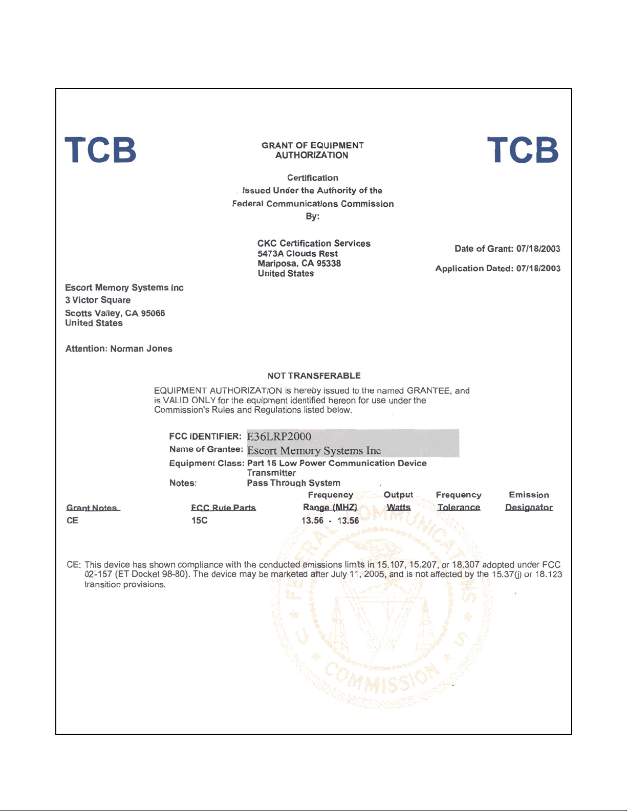
1.3.1 FCC Certifications
3 LRP2000 Passive Reader/Writer
Page 9

Introduction
LRP2000 Passive Reader/Writer
4
Page 10
Introduction
1.4 CE Statement
This product complies with the European Community's CE standards and has been tested and certified to
meet the required standards, EN 300 3300-2 and EN 301 489-3. It is the responsibility of the system
installer to ensure that it is used in compliance with local regulations. Modifying the antenna or controlle r,
or connecting other antennas will void this compliance and is in violation of law.
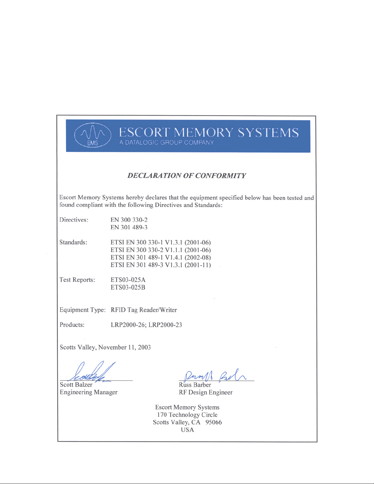
1.4.1 CE Certification
5 LRP2000 Passive Reader/Writer
Page 11

1.5 Changes and Modifications
Any changes or modifications to the LRP2000 not expressly approved by Escort Memory Systems could
void the user's authority to operate the equipment.
Introduction
LRP2000 Passive Reader/Writer
6
Page 12
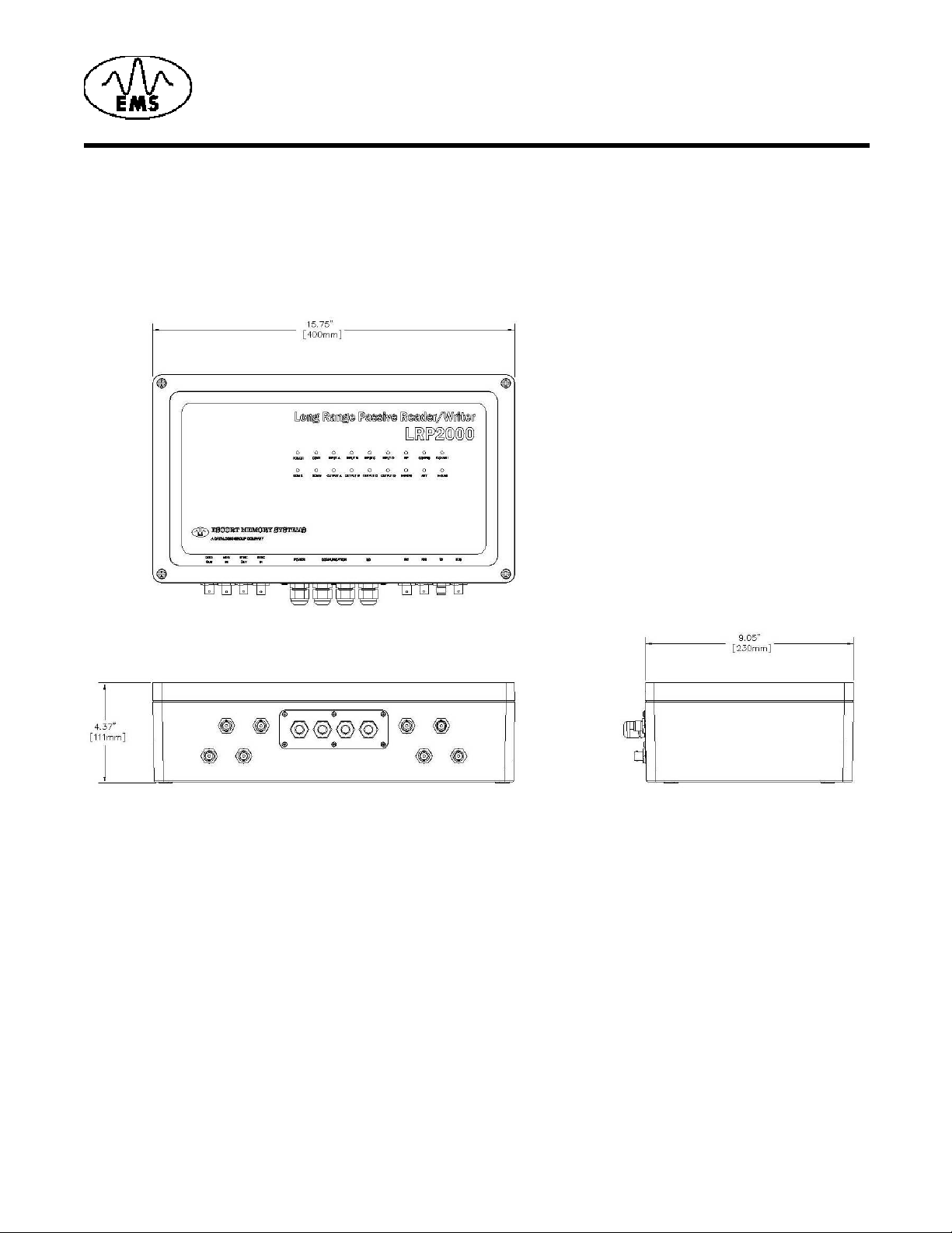
2.1 Dimensions
Figure 1 gives the dimensions for the LRP2000 controller.
2
Installation and Guidelines
Figure 1: LRP2000 Dimensions
7 LRP2000 Passive Reader/Writer
Page 13
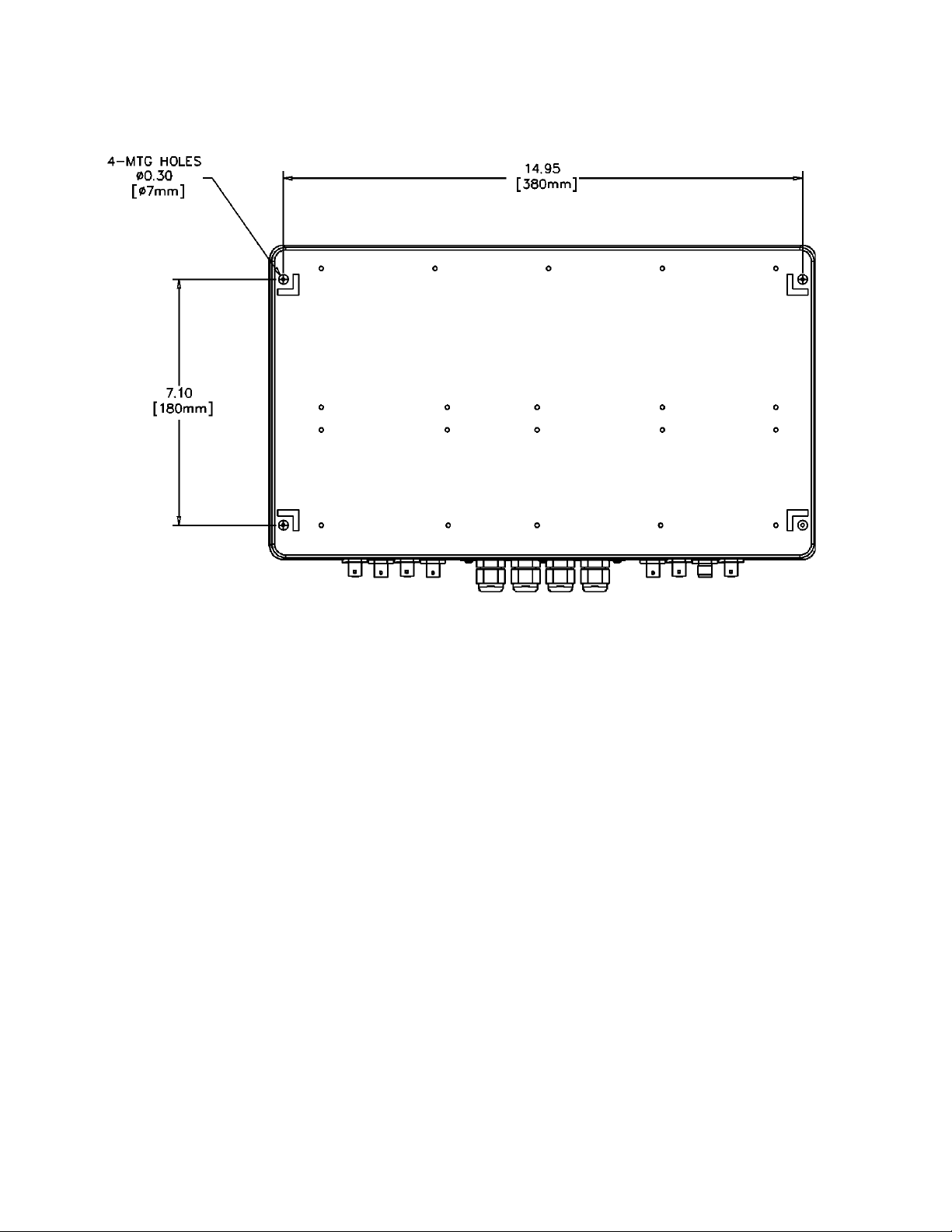
Figure 2 shows the LRP2000 mounting hole locations.
Installation and Guidelines
Figure 2: LRP2000 Mounting Hole Locations and Dimensions
LRP2000 Passive Reader/Writer
8
Page 14
Installation and Guidelines
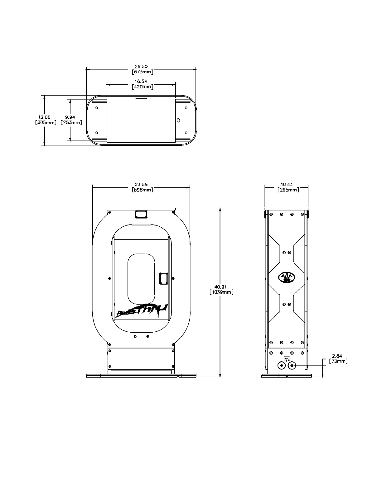
Figure 3 gives the dimensions for the LRP2000-23 antenna
Figure 3: LRP2000-23 Antenna Dimensions
9 LRP2000 Passive Reader/Writer
Page 15
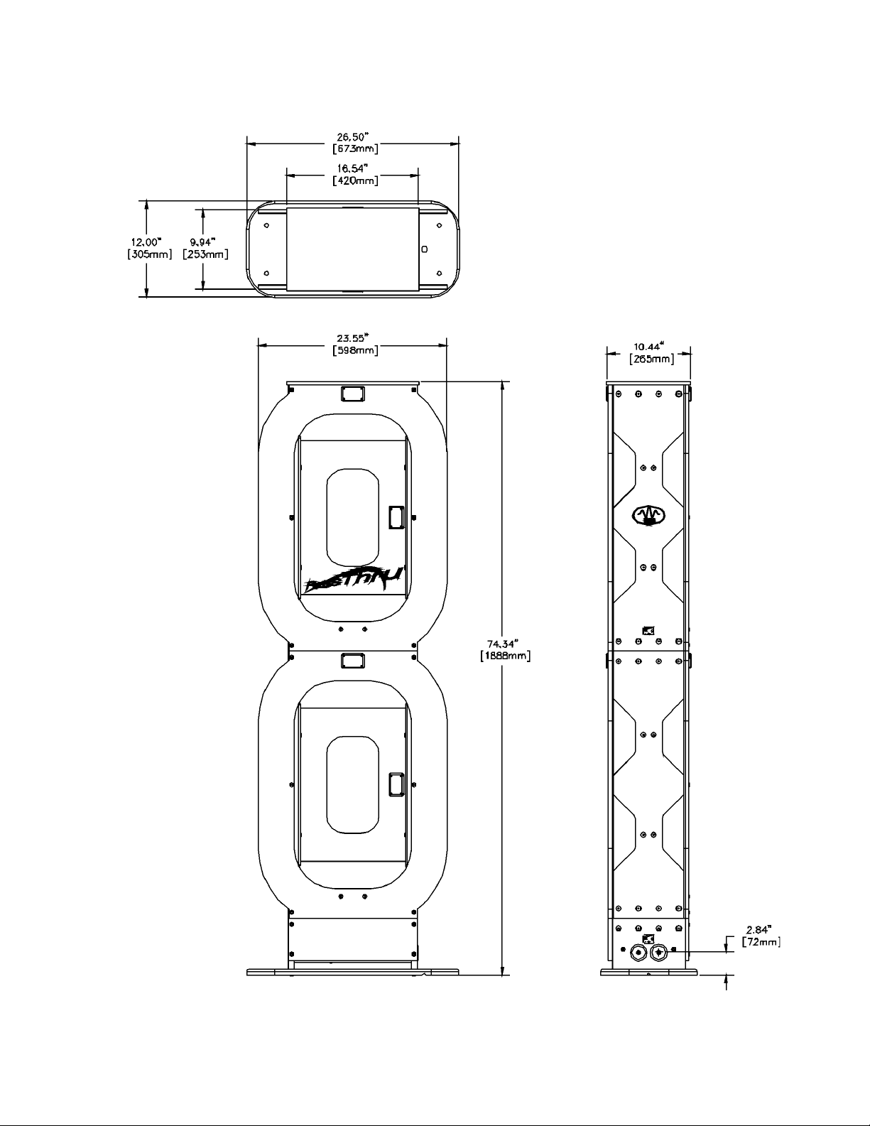
Figure 4 gives the dimensions for the LRP2000-26 antenna.
Installation and Guidelines
Figure 4: LRP2000-26 Antenna Dimensions
LRP2000 Passive Reader/Writer
10
Page 16
Installation and Guidelines
2.2 Installation
Antenna Environment
Electromagnetic radiation and the presence of met al within the reading field of the antenna af fect the range
of the LRP2000. Mount the antenna to minimize the impact of these factors.
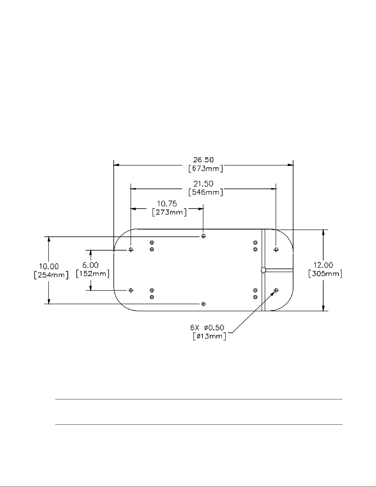
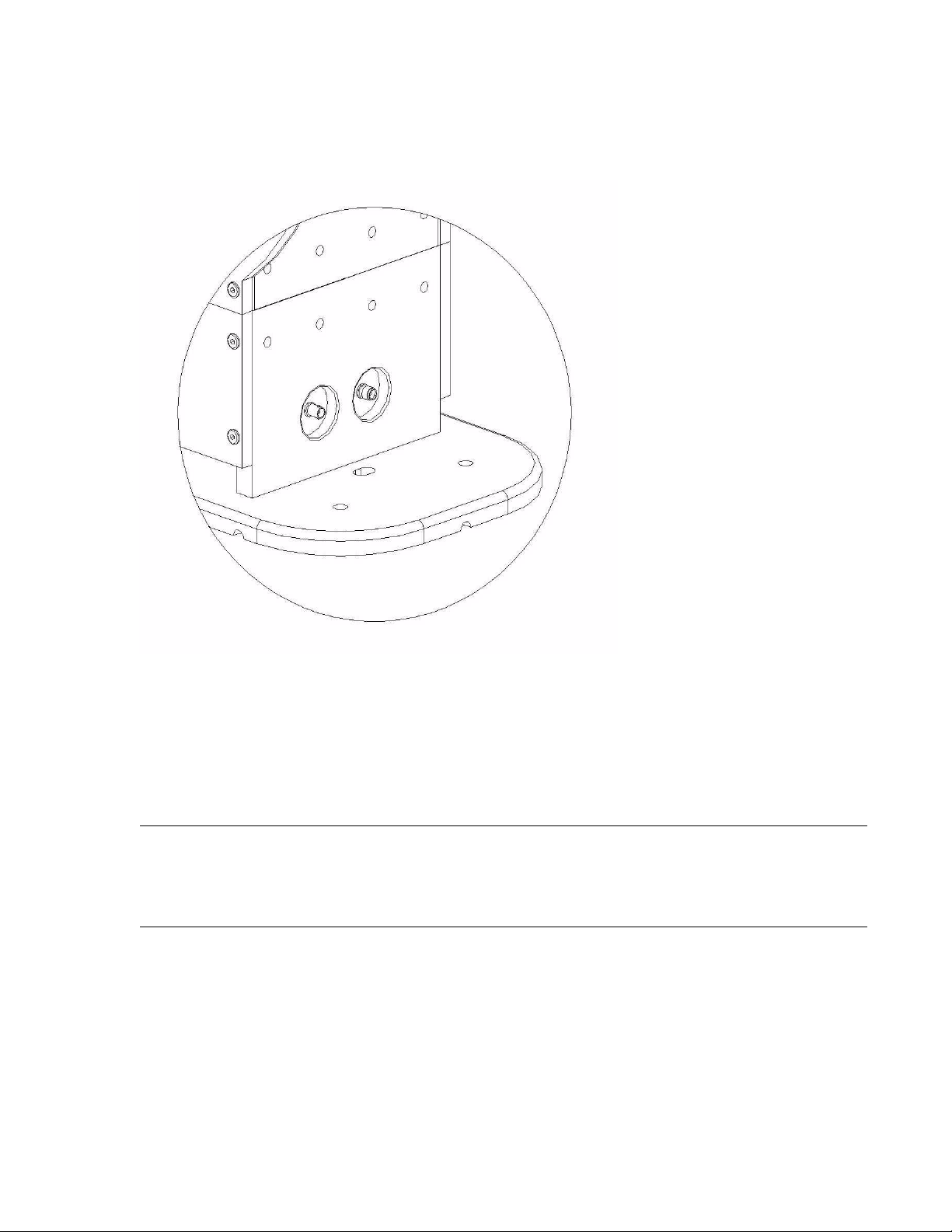
Installing the Antenna
Once a suitable location is selected for the LRP2000 antenna, the structure should be securely bolted to
the floor using the holes provided in the base. The dimensions for the antenna bolt pattern are shown in
Figure 5.
Mount the antenna at least 36” away from large metal objects. The antenna emits RF fields from both
sides. Avoid placing metal in front of or behind the antenna.
Figure 5: Antenna Base Bolt Pattern
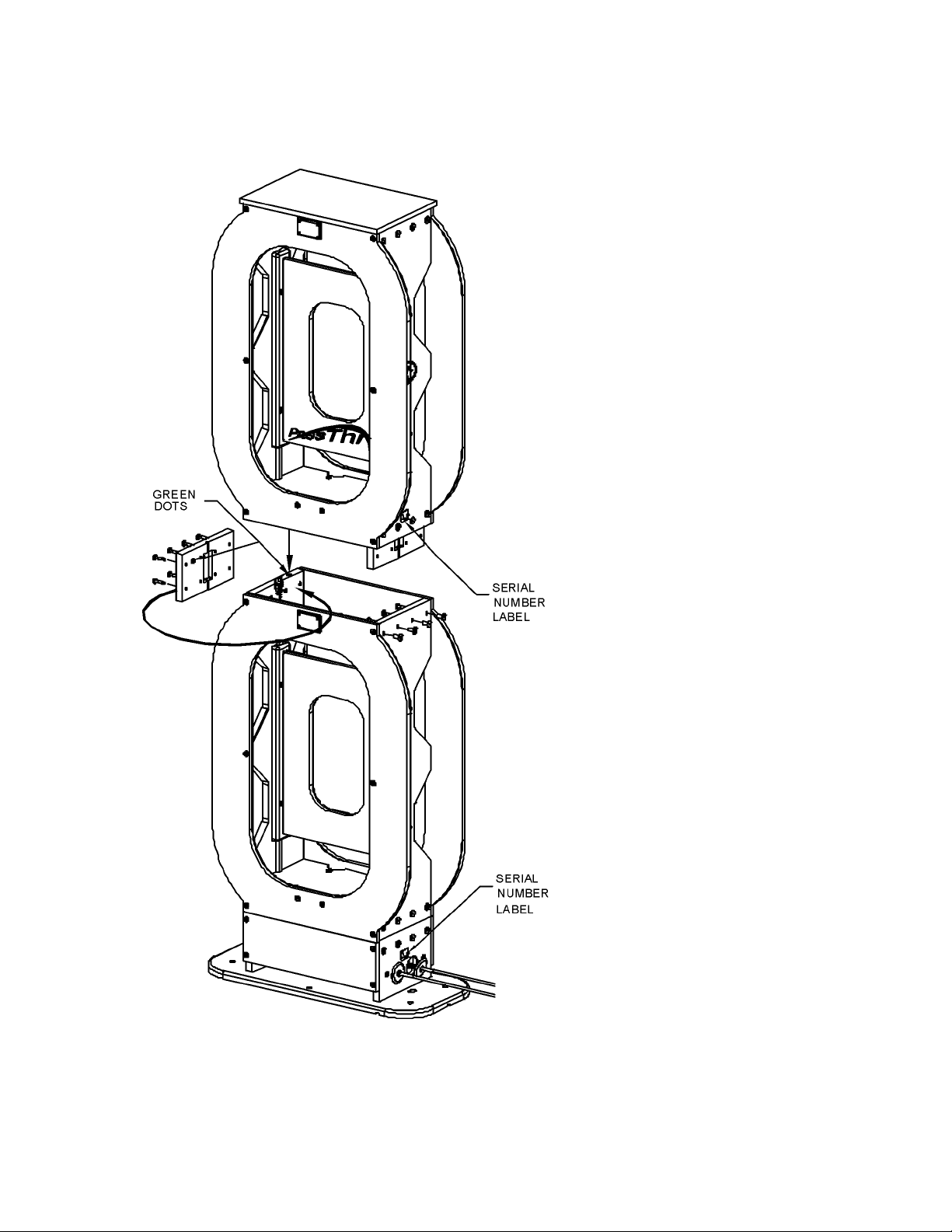
2.2.1 LRP2000-26 Antenna Assembly
The LRP2000-26 antenna is shipped in two parts. The following instructions describe how to correctly
assembly an LRP2000-26 antenna.
CAUTION:If you are assembling more than one LRP20 0 0- 26 , you mu st as se mb le halve s with mat ch ing
serial numbers. The complete antenna is tuned at EMS before shipping and mis-matching the
halves will degrade performance.
11 LRP2000 Passive Reader/Writer
Page 17
Installation and Guidelines
To assemble the LRP2000 antenna:
1. Place the base half on a flat surface and note the position of the green dots shown in Figure 6.
Figure 6: Green Orientation Dots Location
LRP2000 Passive Reader/Writer
12
Page 18
Installation and Guidelines
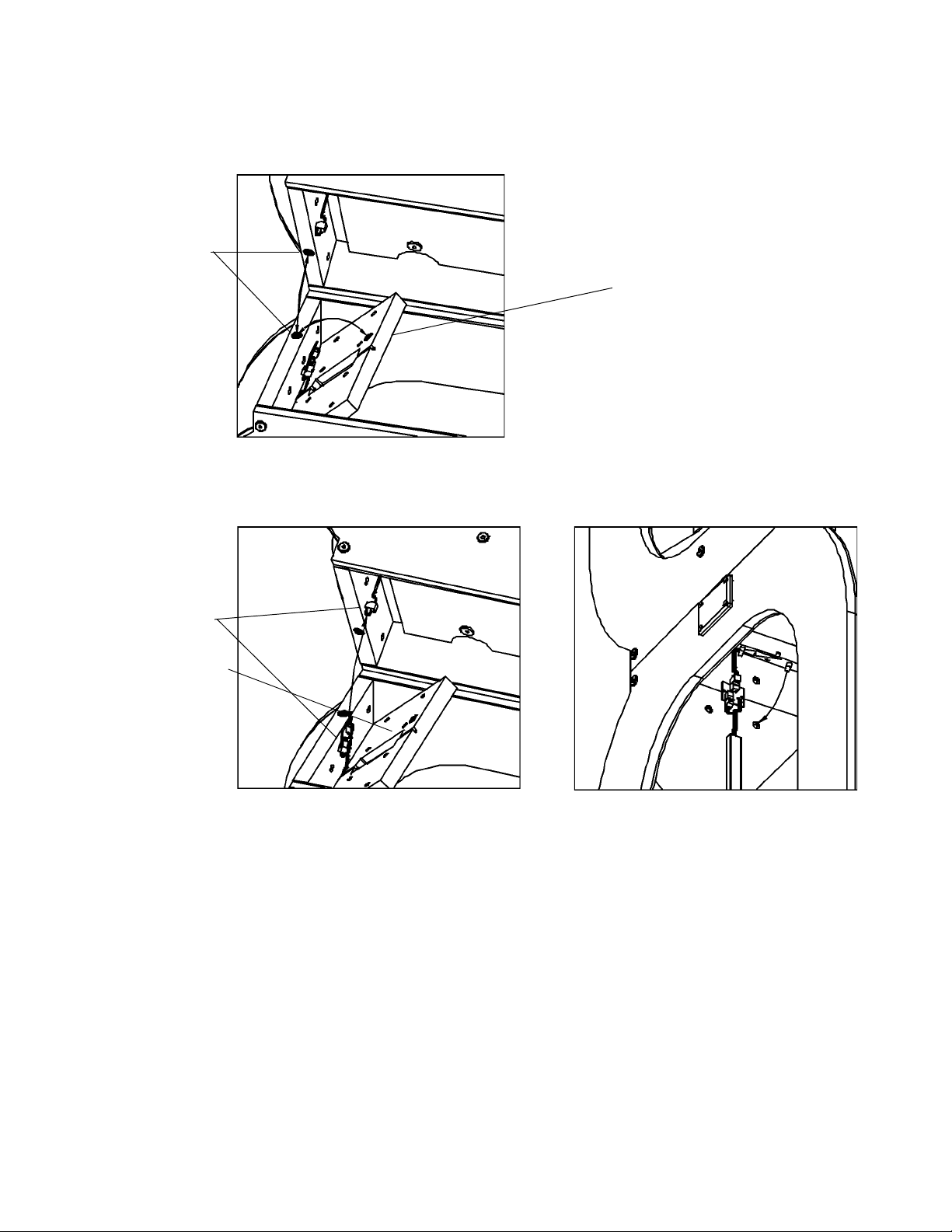
2. Align the halves according to the green dots and place the top half of the anten na on the base half. See
Figure 7. Check that the halves have matching serial numbers (see Figure 6).
Green Dots
Figure 7: Green Dot Alignment
3. Make the electrical connection between the two halves as shown in Figure 8.
Joining Plate
Connectors
Joining Plate
Figure 8: Antenna Electrical Connection
13 LRP2000 Passive Reader/Writer
Page 19
Installation and Guidelines
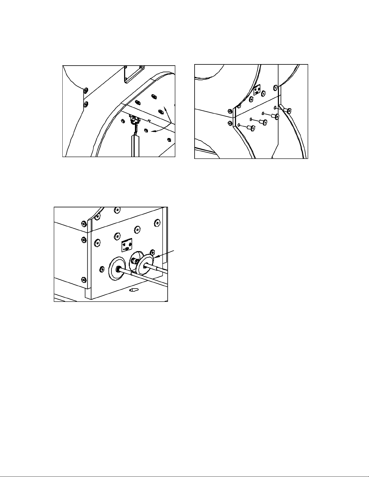
4. Slide the joining plate into place from below and secure the top row of fasteners. Make sure you do not
bind the connector or wire under the joining plate.
Figure 9: Joining Plate and Fasteners
5. Repeat on the other side of the antenna.
6. Fasten the bottom row of joining plate connectors on both sides.
7. Connect the cables to the LRP2000 and slide the over the connector as shown in Figure 10.
Figure 10: Antenna Cables and Seals
LRP2000 Passive Reader/Writer
14
Page 20
Installation and Guidelines
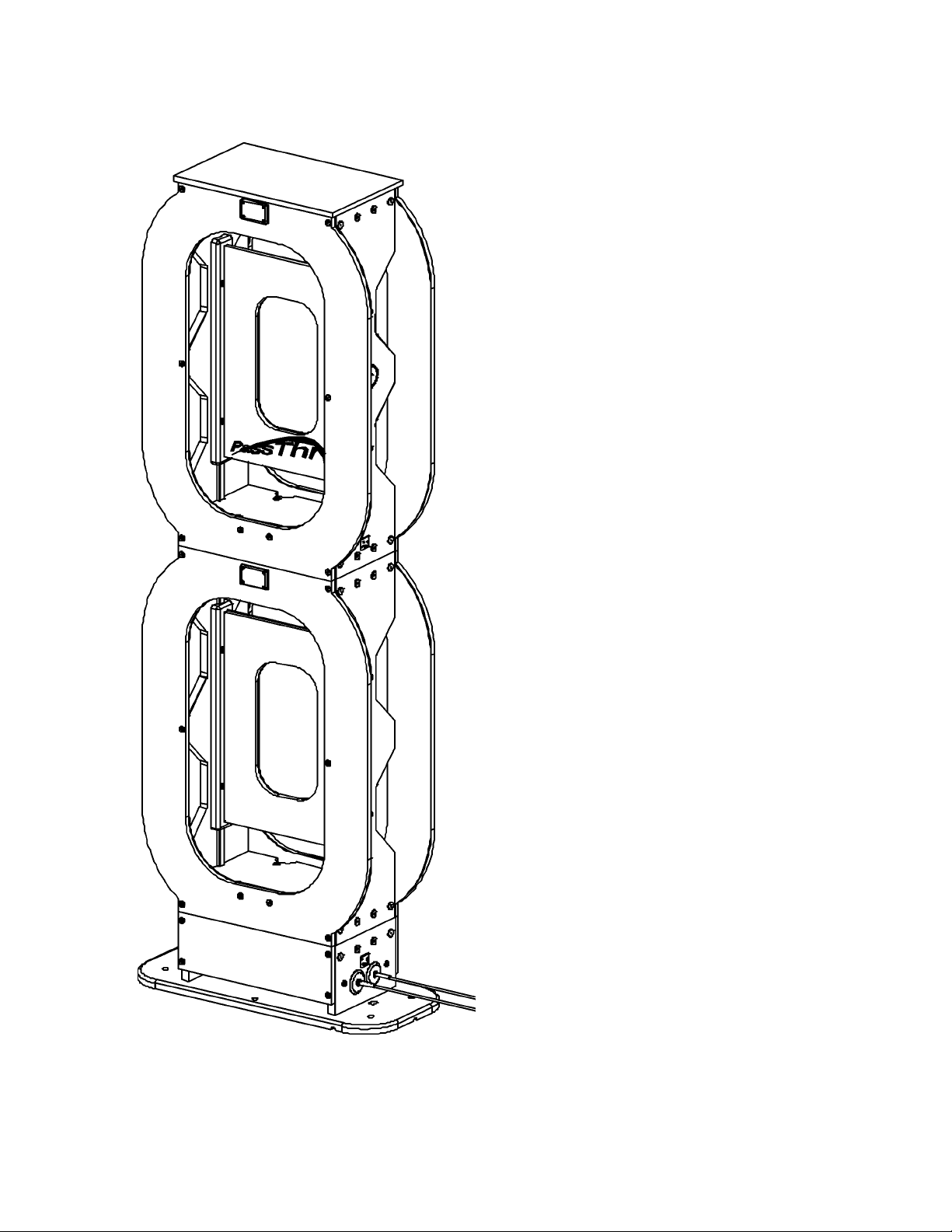
Figure 11 shows a completed LRP2000-26 antenna.
Figure 11: Completed LRP2000-26 Antenna
15 LRP2000 Passive Reader/Writer
Page 21
3.1 Connectors and Wiring
Figure 12 shows the front connector panel with the four strain reliefs and the RF connectors. The controller
ships with sealing plugs in the strain reliefs. For an environmental seal, leave these plugs in place for any
unused location.
3
Electrical Interface
Figure 12: RF Connectors and Strain Relief
The four strain reliefs can seal cables ranging in diameter from 0.12” [3.0 mm] minimum to 0.32” [8.0mm]
maximum diameter.
16 LRP2000 Passive Reader/Writer
Page 22
Electrical Interface
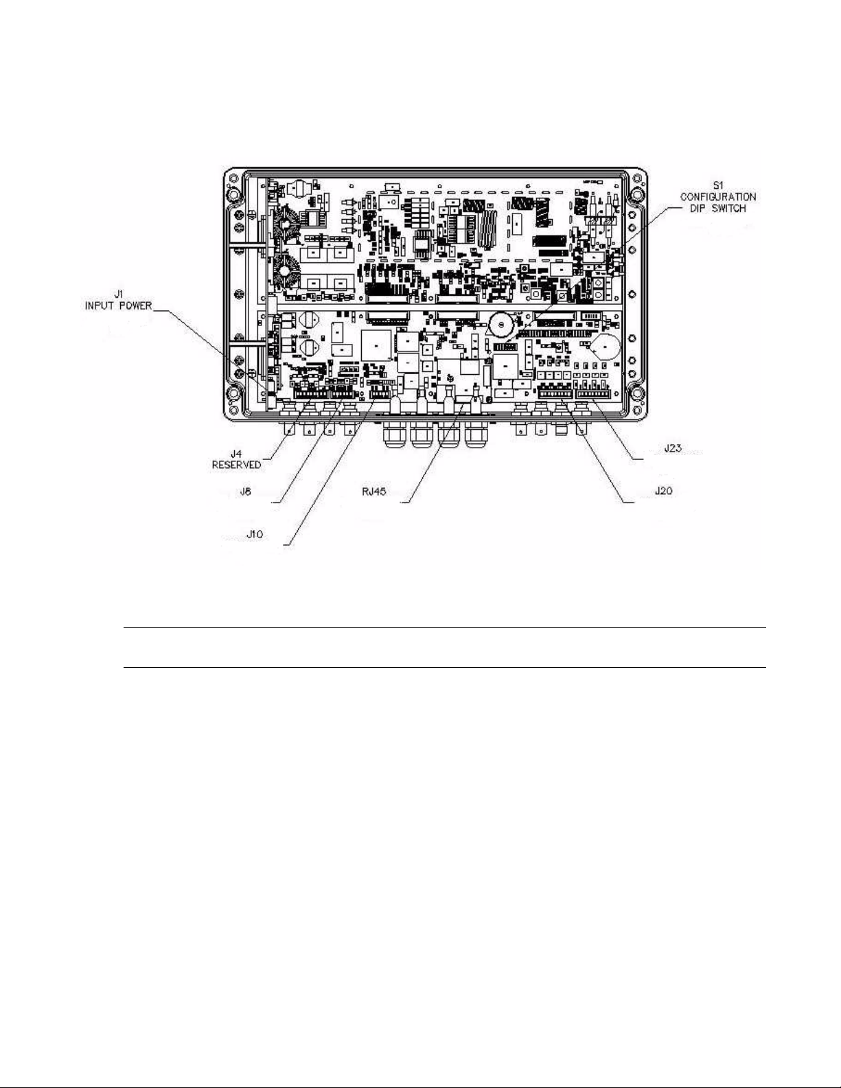
Figure 13 shows an internal view of the controller. It details the locations of all internal terminal blocks
needed for wiring the system.
Figure 13: Internal Connectors
CAUTION:The controller contains ESD-sensitive components. Always observe ESD-sensitive handling
procedures when working inside the controller.
Terminal Blocks
The controller is equipped with removable terminal blocks to aid wiring. The data terminals are all
equipped with screw terminals, which accept AW G 28 minimum to AWG 16 maximum diameter solid or
stranded wire. The screw heads accept a 3/32 inch [2.0 mm] or [2.5 mm] screwdriver blade.
17 LRP2000 Passive Reader/Writer
Page 23
3.2 Antenna Cabling
Figure 14 shows the two antenna connectors at the base of the LRP2000 antenna.
Electrical Interface
Figure 14: Antenna Connectors
Connect one end of the antenna cable assembly, CBL-1475, to the antenna connectors at the base of the
antenna. Mate the connectors at the opposite end of the cable assembly to the corresponding RF
connector on the controller . The cable assembly has two different types of RF connectors, one threaded
TNC and one bayonet-style BNC. The controller has one TNC and seven BNC connectors. The BNC
connector of the antenna cable assembly must only be connected to the controller connector for single
antenna systems.
CAUTION:The antenna cables must be properly connected to both the controller and the antenna at any
time that power is applied to the controller. Failure to properly connect the controller to the
antenna can cause damage to the unit. Connecting the controller to any antenna other than the
LRP2000 antenna can not only damage the controller, but void the your authority to operate the
LRP2000.
LRP2000 Passive Reader/Writer
18
Page 24
Electrical Interface
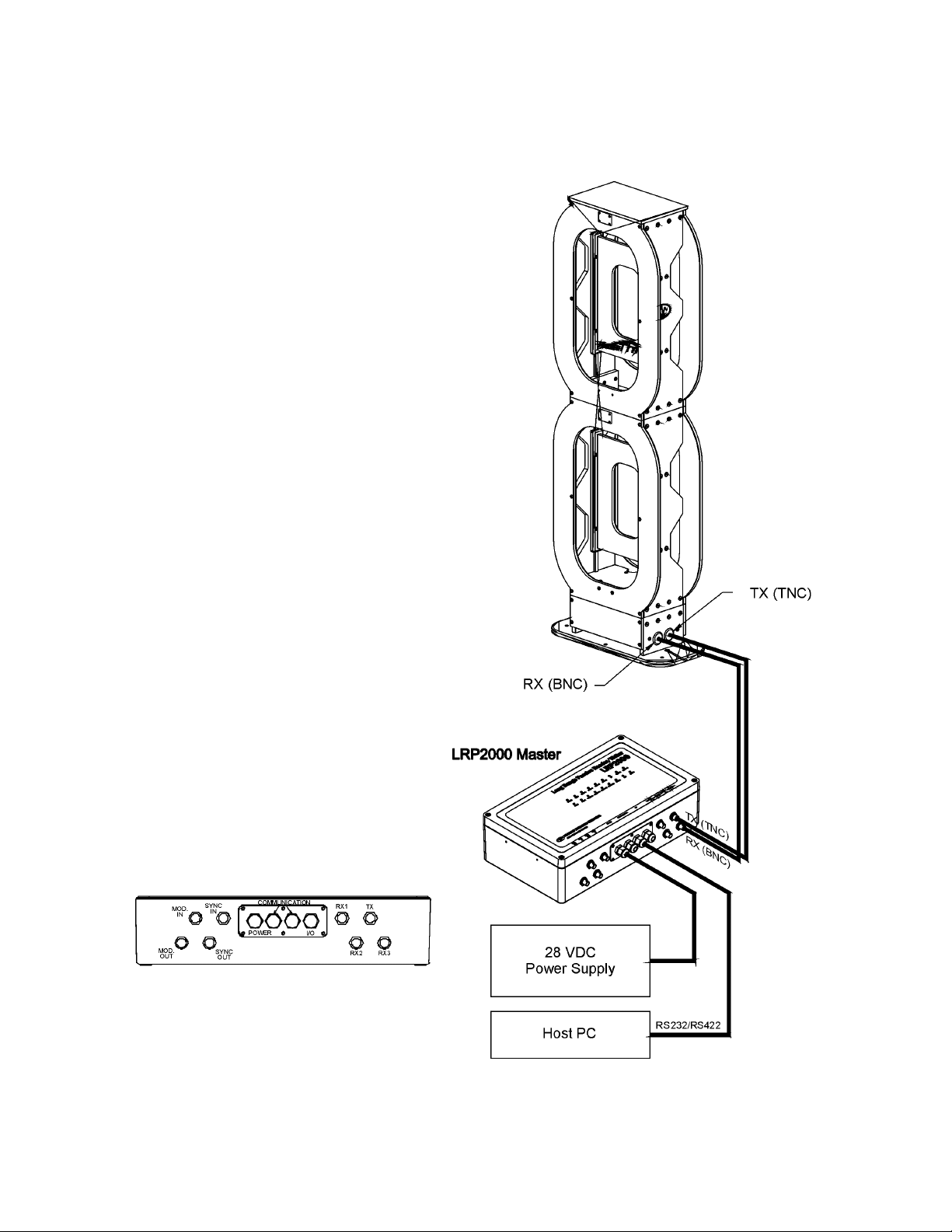
3.2.1 Connecting Single Antenna System
Figure 15 shows how to connect the LRP2000 and antenna in a single antenna configuration.
Figure 15: Single Antenna System Connections
19 LRP2000 Passive Reader/Writer
Page 25
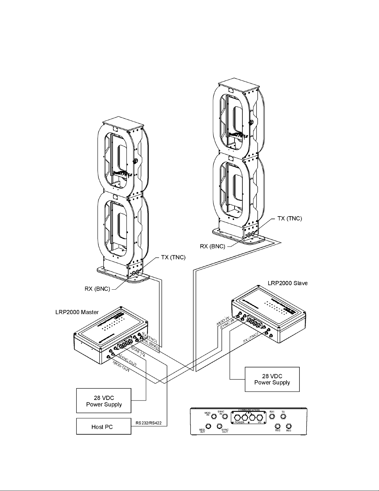
3.2.2 Connecting a Dual Antenna System
In dual antenna systems, one LRP2000 serves as the master and the other acts as the slave. Figure 16
shows how to connect two LRP2000s in a master/slave configuration.
Electrical Interface
Figure 16: Dual Antenna System Connections
LRP2000 Passive Reader/Writer
20
Page 26
Electrical Interface
3.3 Data Terminal Blocks
Figure 17 shows the LRP2000 RS232 terminal block J8, and a detail view the terminal arrangement.
Figure 17: J8 COM1 RS232/COM2 RS232
Table 1 lists the RS232 pinouts.
Table 1: RS232 Pinouts, J8 Terminal Block
J8 Pin Number Interface J8 Signal Name
1 COM1 RS232 RX 3 2
2 COM1 RS232 TX 2 3
3 COM1 RS232 GND 5 7
4 COM2 RS232 RX 3 2
5 COM2 RS232 TX 2 3
6 COM2 RS232 GND 5 7
NOTE: The signal names given in Table 1 refer to the signals from the LRP2000, not from the host. The
DB9 Pin
Number
DB25 Pin
Number
DB9 and DB25 pin numbers are from standard RS232 connectors.
21 LRP2000 Passive Reader/Writer
Page 27
Electrical Interface
Figure 18 shows the LRP2000 COM1 RS422 terminal block, J10, and a detail view illustrating the
arrangement of the terminals.
Figure 18: J10 COM1 RS422
LRP2000 Passive Reader/Writer
22
Page 28
Electrical Interface
Table 2: J 10 Pinout
J10 Pin Number Signal Name Polarity Description
1 TX - - Negative Transmits data to host
2 TX + + Positive Transmits data to host
3 GND Neutral Signal reference
4 RX - - Negative Receives data from host
5 RX + + Positive Receives data from host
The signal names given in Table 2 refer to the signals from the LRP2000, not the signals from the host.
3.4 Power Supply Wiring
CAUTION:The antenna cables must be properly connected to both the controller and the antenna at any
time that power is applied to the controller. Failure to properly connect the controller to the
antenna can cause damage to the unit. Connecting the controller to any antenna other than the
LRP2000 antenna can not only damage the controller, but can void your authority to oper ate the
LRP2000.
Loosen the terminal screws on the terminal block of the power supply and connect the spa de lugs of Cable
CBL-1474 to the terminals according to Table 3. Strip 1/4 inch from the opposite ends of the cable
assembly and connect to the input power terminals according to Table 3.
CAUTION:Only after all internal connections are completed should the LRP2000 power supply be
connected to the AC mains.
Table 3: Input Power Pinout
Power Supply
Connector
+28 RED 3
- RTN BLACK 2
GND Tin 1
Wire color
LRP2000
Connector Pin
Number
23 LRP2000 Passive Reader/Writer
Page 29
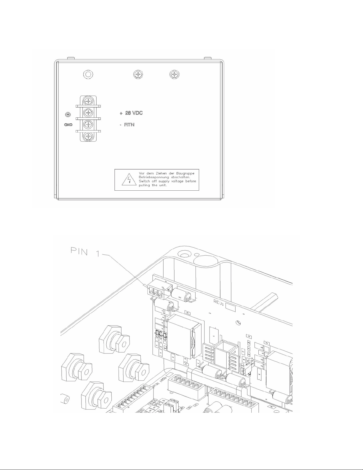
Figure 19 shows the LRP2000 power supply and spade lugs.
Electrical Interface
Figure 19: Input Power Supply Lugs
Figure 20 shows the LRP2000 input power terminals.
Figure 20: 28 VDC Input Power Terminals
LRP2000 Passive Reader/Writer
24
Page 30
Electrical Interface
3.5 RS232 Wiring
The recommended cable type for RS232 communication is Belden par t number 9941. Specifications for
Belden cables can be found at WWW.BELDEN.COM.
3.6 RS422 Wiring and Termination
In installations where long cable runs must be used, or in noisy environments, RS422 is the
communications standard of choice for point-to-point serial communications. The recommended cable
types are Belden p/n 3084A, or Belden p/n 30 82A. For long cable lengths, make sure you consider voltage
drop over the length of the cable, and use cable of an adequate gauge.
NOTE: The RS422 receiver within the LRP2000 controller has fail-safe protection circuitry, which
eliminates the need for any pull-up or pull-down resistors on the RS422 lines.
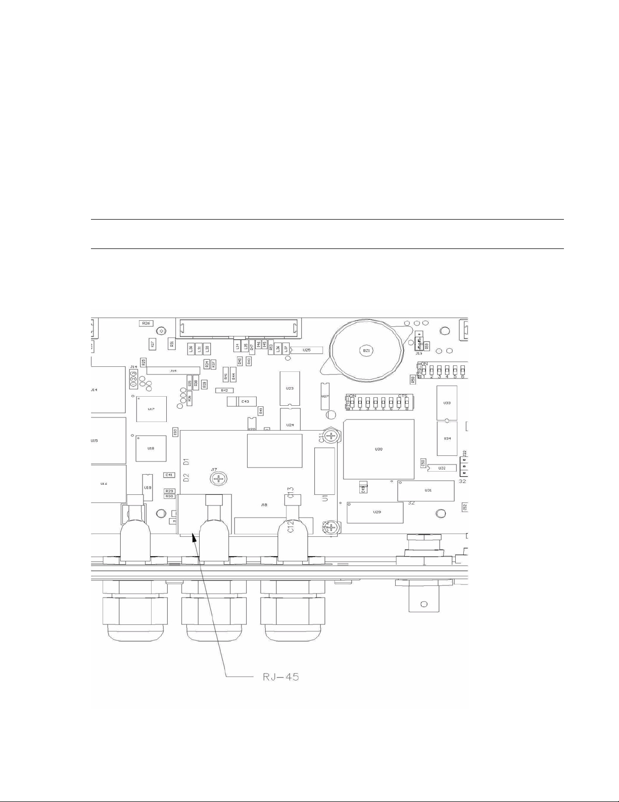
3.7 Ethernet Wiring
Figure 21: RJ-45 Connector on the Optional Ethernet Module
25 LRP2000 Passive Reader/Writer
Page 31

Because of the narrow size of the strain reliefs on the LRP2000, the standard RJ-45 connector cannot be
inserted through the strain relief. EMS recommends that you loosen the nut on the strain relief, feed
through the cable, and crimp the connector in place. After the connector is crimped onto the cable, the
cable can be connected to the Ethernet module, and the excess cable withdrawn from the unit before
tightening the strain relief. EMS recommends stranded shielded CAT5e cable for Ethernet wiring.
Ethernet capability is an optional upgrade. Contact your EMS dealer for inquiries about availability of this
option and upgrade.
3.8 Digital I/O Circuitry
Both the digital inputs and digital outputs are optically isolated circuits with no common path between any
channel terminal and another channel, or between any channel and the LRP2000 power. Because they
are independent and floating, the external wiring controls their use. The inputs can be configured for
sensors with a PNP or NPN output. The outputs can be configured in a sourcing or sinking configuration.
The examples in Figure 24 through Figure 31 show different connections for common input and output
devices.
Electrical Interface
LRP2000 Passive Reader/Writer
26
Page 32

Electrical Interface
3.8.1 Inputs
The +IN terminal must be at a higher positive potential than the -IN terminal for current to be sensed
correctly. The voltage range is 4.5 to 30V between the +IN and the -IN inpu t s, and the maximum current is
25 mA.
Figure 22: J23 Input Connector
Table 4: Input Connector Pinout
Connector Pin
Number
1 + IN A Positive
2 - IN A Negative
3 + IN B Positive
4 - IN B Negative
5 + IN C Positive
Signal Name Polarity
27 LRP2000 Passive Reader/Writer
Page 33

Table 4: Input Connector Pinout
Electrical Interface
Connector Pin
Number
6 - IN C Negative
7 + IN D Positive
8 - IN D Negative
9 GND Neutral
3.8.2 Outputs
The output is limited to 30 VDC when off and 500 mA. These ar e maximum ratings. A de vice that operates
at 200 mA may destroy the output due to inrush current if that current exceeds 500 mA (such as an
incandescent light). The inductive kick (back EMF from a collapsing magnetic field) wh en a relay is
released can impose a voltage higher than 30 V and destroy the output transistor (use a backwards diode
to clamp the back EMF).
Signal Name Polarity
LRP2000 Passive Reader/Writer
28
Page 34

Electrical Interface
Figure 23: J20 Output Connector
Table 5: Output Connector Pinout
Terminal
Number
1+ OUT APositive
2 - OUT A Negative
3+ OUT BPositive
4 - OUT B Negative
5+ OUT CPositive
6 - OUT C Negative
7+ OUT DPositive
8 - OUT D Negative
9 GND Neutral
Signal Name Polarity
29 LRP2000 Passive Reader/Writer
Page 35

Electrical Interface
Figure 24: Input from Sourcing Contact
Figure 24 shows the switch on the high side with the low side grounded. As this is a “Dry” contact (the
current is limited to 15 mA), a high-quality sealed switch should be used.
Figure 25: Input from Sinking Contact
Figure 25 shows a switch connected on the low side with the high side connected to the positive supply.
This also requires a high-quality sealed contact.
LRP2000 Passive Reader/Writer
30
Page 36

Electrical Interface
Figure 26: Input from NPN Sensor
Figure 26 shows an Open Collector NPN output from a photosensor switching to ground. It can be wired
as a sinking or low-side contact.
Figure 27: Input from NPN Sensor
Figure 27 shows an Open Collector PNP output from a photosensor switching to a positive supply. It can
be wired as a sourcing or high-side contact.
31 LRP2000 Passive Reader/Writer
Page 37

Electrical Interface
Figure 28: Sourcing Output 'Contact
Figure 28 shows a relay connected as a current sourcing “Contact.” The relay is grounded and the +OUT
terminal goes to the positive supply. The diode across the relay coil is essential to protect the output circuit
and reduce noise along the wiring. It should be connected at the relay to minimize the length of wiring that
could radiate noise. A 1N4001 or similar diode may be used.
Figure 29: Sinking Output 'Contact
Figure 29 shows a “Contact” sinking current from a relay. The -OUT terminal is grounded and the relay
goes to the positive supply. This configuration must also have a diode across the relay coil to protect the
circuit and reduce noise.
LRP2000 Passive Reader/Writer
32
Page 38

Electrical Interface
Figure 30: Sinking Output LED Driver
In Figure 30, the LED and current limiting resistor are in series between the positive supply and the +OUT
terminal. The -OUT terminal is grounded. The resistor in series with the LED sets the forward current.
1.2 K provides 20 mA LED current when run from 24 VDC.
Figure 31: Output to TTL or CMOS LogicIn
In Figure 31, the output acts as an Open Collector. This provides a TTL or CMOS compatible signal when
a 1 K to 10 K pull-up to +5 Vdc (the logic supply) is used.
33 LRP2000 Passive Reader/Writer
Page 39

3.9 Master/Slave Configuration
You can use the LRP2000 in a single or dual antenna configur ation . All LRP2000s are set by default to be
master controllers for single antenna systems. For dual antenna systems, you must make one jumper
change to the master and change the second controller to a slave.
To change an LRP2000 to act as a slave, you ne ed to perform the following tasks:
• Move a shunt from jumper J34 to jumper J32 (master LRP200).
• Make DIP switch setting changes to DIP switch banks S1 and S2 (slave LRP200).
• Change the location of jumper J16 (slave LRP200).
The following sections describe how to make these changes.
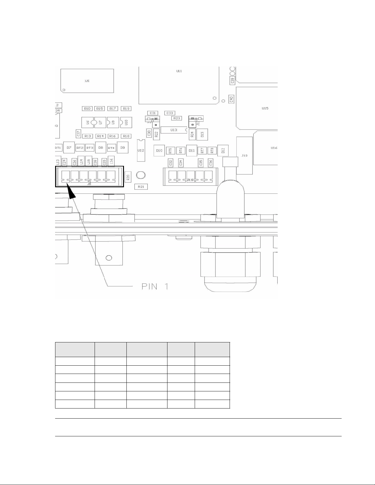
3.9.1 Setting Jumper 32 on the Master
You must make one jumper change to the LRP2000 you have se lected to be the master.
To set jumper 32 for a dual antenna master:
1. Verify that power to the LRP2000 is off.
2. Locate jumper 32 and jumper 34 as shown in Figure 32.
Electrical Interface
Figure 32: Jumpers 32 and 34
3. Remove the shunt from jumper 34 and place it over jumper 32.
LRP2000 Passive Reader/Writer
J32
J34
34
Page 40

Electrical Interface
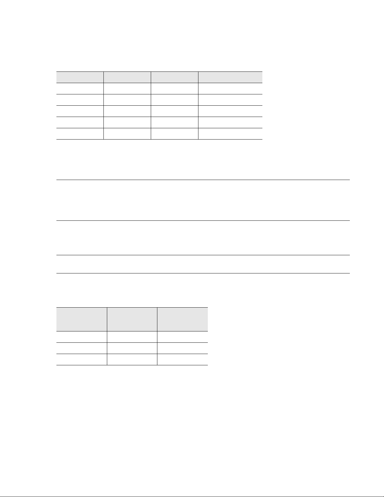
3.9.2 DIP Switch Settings on the Slave
To set a LRP2000 to operate as a slave in a dual anten na inst allation, you must change the settings of DIP
switch banks S1 and S2.
For reference, Table 6 shows the settings for a master LRP2000. The correct settings for switch banks S3
and S5 are also shown. Figure 33 shows the locations of the switch banks.
Table 6: Master DIP Switch Settings
Bank Position 1 Position 2 Position 3 Position 4 Position 5 Position 6 Position 7 Position 8
S1 OFF OFF OFF OFF OFF ON OFF OFF
S2 ON ON OFF ON OFF OFF OFF ON
S3 OFFONONONOFFOFFONON
S5 ON ON ON ON ON ON ON ON
S2
S1
Figure 33: DIP Switch Banks S1, S2, S3, and S5
S3
S5
35 LRP2000 Passive Reader/Writer
Page 41

To change the switches to a slave configuration, make the changes highlighted in Table 7. Make sure
power to the LRP2000 is off before changing DIP switch settings.
Table 7: Slave DIP Switch Settings
Bank Position 1 Position 2 Position 3 Position 4 Position 5 Position 6 Position 7 Position 8
S1 OFFOFFOFFOFFOFFOFFOFFOFF
S2 ON OFF ON ON OFF OFF OFF ON
S3 OFFONONONOFFOFFONON
S5 ON ON ON ON ON ON ON ON
NOTE: Do not make any changes to switch bank S3 and S5.
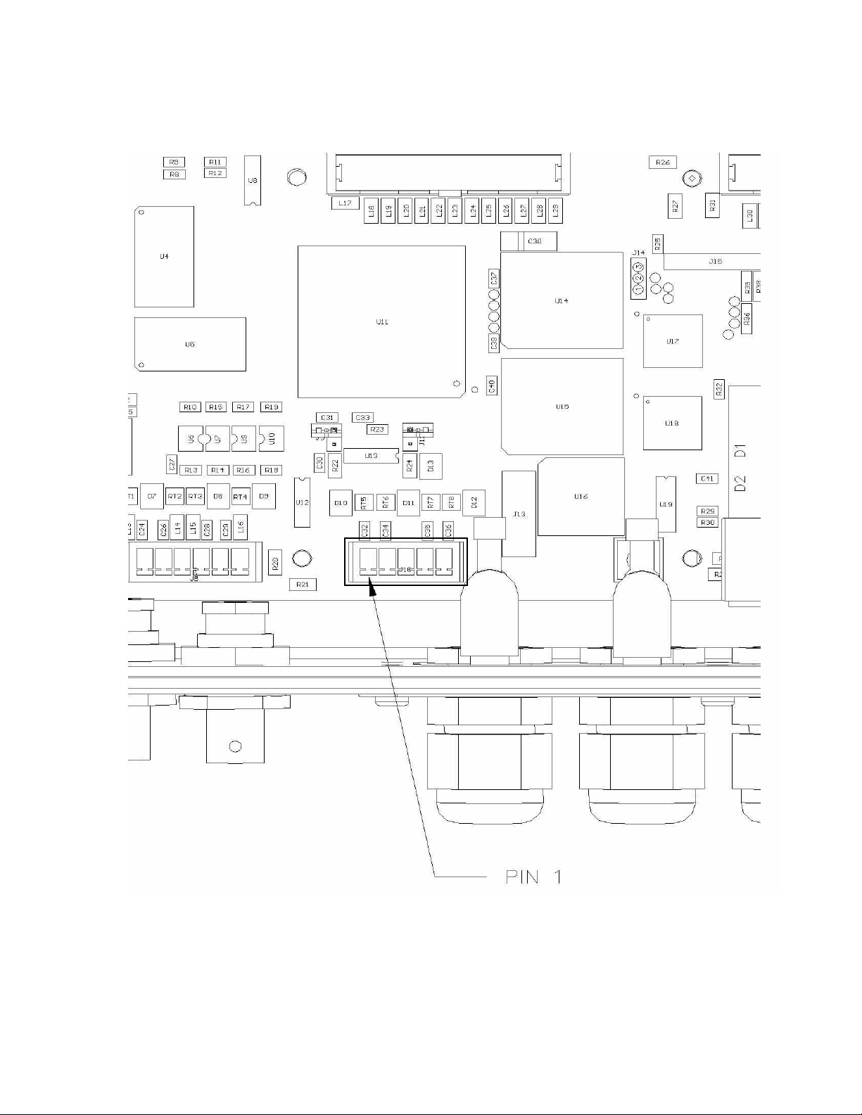
3.9.3 Setting Jumper J16 on the Slave
Jumper J16 is a three-pole jumper located under the transmitter shield.
To change the J16 jumper to the slave setting:
1. Verify that power to the LRP2000 is off.
2. Straighten the tabs retaining the transmitter shield and remove the shield.
jumper J16 is located on the left side of the first compartment.
3. Move the J16 shunt from the up position (pins 1 and 2) to the down position (pins 2 and 3). See
Figure 34 below.
Electrical Interface
Figure 34: Jumper J16 Position
4. Replace the transmitter shield and fold over tabs to lock the shield in place.
LRP2000 Passive Reader/Writer
36
Page 42

Communications Interface
4.1 Configuring the Serial Interface
4.1.1 COM1
In normal use for reading and writing RFID tags, communications with the LRP2000 occurs via the main
communications interface, COM1. This communications interface can be accessed by both point-to-point
and addressed serial communications protocols. For point-to -point serial communication, the LRP2000
supports RS232 and RS422 as the standard protocols. For multiplexed communications, Ethernet is
available as an option. The RS422 interface is especially suited for long cable lengths, and for noisy
environments.
NOTE: The delay between the characters sent to the controller cannot be longer than 200 ms.
The options for each configuration parameter for the COM1 interface are listed in Table 8.
Table 8: COM1 Parameters
4
Baud rate
Number of Data Bits 7, 8
Number of Stop Bits 1
Parity Even, Odd, None
Flow Control None, Xon/Xoff
The default configuration parameters for COM1 are listed in Table 9.
Table 9: COM1 Defaults
Baud rate 9600 bps
Number of Data Bits 8
Number of Stop Bits 1
Parity None
Flow Control None
4.1.2 COM2
For the purpose of configuring the controller's operating parameters, communication occur via the auxiliary
communications interface, COM2. This auxiliary interface only communicates via RS232 and is reserved
for configuring and updating the operating parameters, and for updating the firmware in the controller. For
example, with the correct hardware dip switch settings, the COM2 interface can be used to configure the
parameters of the COM1 interface. The electronics of this interface are also optically isolated from the
other circuits of the controller.
1200, 2400, 4800, 9600,
19200, 38400 bps
37 LRP2000 Passive Reader/Writer
Page 43

The communication options for the COM2 interface are listed in Table 10.
Table 10: COM2 Parameters
Communications Interface
Baud Rate
Number of Data Bits 7, 8
Parity Even, Odd, None
Flow Control None, Xon/Xoff
1200, 2400, 4800,
9600, 19200 bps
The default configuration parameters for COM2 are listed in Table 11.
Table 11: COM2 Defaults
Baud Rate 9600 bps
Number of Data Bits 8
Number of Stop Bits 1
Parity None
Flow Control None
LRP2000 Passive Reader/Writer
38
Page 44

Communications Interface
4.1.3 Digital Board DIP Switch
The digital board is mounted inside the LRP2000 enclosure closest to the wall with the cable entries. The
first five switches of the main board set the COM1 baud rate, electrical interface, and the download options
for COM2. SW6, SW7 and SW8 are not used and should remain OFF. When SW1 and SW2 are both set
ON, the baud rate is set via the Configuration Menu. Table 12 lists the possible switch settings for typical
applications.
Figure 35: Configuration Dip Switch, S1
Figure 35 shows the location of the digital board dip switches, and hardware reset switch. It also includes a
detail view of the dip switch array , which indicates the arrangement of the switches from left to right and the
“ON” and “OFF” directions.
Table 12: Dip Switch Settings
Download/
Baud Rate Interface
SW1 SW2 SW3 SW4 SW5 Settings
OFF OFF * * OFF 9600 BAUD
ON OFF * * OFF 19200
OFF ON * * OFF 38400
ON ON * * OFF Set from Configuration Menu
* * OFF OFF OFF RS232
* * ON OFF OFF RS422
IGNORED IGNORED IGNORED ON OFF Ethernet
Restore
Defaults
39 LRP2000 Passive Reader/Writer
Page 45

Communications Interface
Table 12: Dip Switch Settings
Download/
Baud Rate Interface
IGNORED IGNORED ON ON OFF Reserved
OFF OFF OFF OFF OFF Disabled
IGNORED IGNORED IGNORED IGNORED ON Download / Restore Defaults
NOTE: By setting SW5 ON to enable download, the default parameters will first be restored and saved to
Restore
Defaults
the non-volatile memory, erasing the previously stored communication and operating parameters.
These parameters will take effect after a hard reset or a power-on reset. A hard reset is invoked by
depressing the hard reset switch, holding for one second, and releasing. The hard reset switch is
shown in Figure 35.
The baud rate, as determined by SW1 and SW2, only applies to the COM1 serial interface. When the
optional Ethernet interface is selected by setting SW4 to the “ON” position, the baud rate is set
automatically for Ethernet communication, and SW1 and SW2 are ignored.
The communication parameters for CO M2 can only be changed by menu configuration. Because COM2 is
an auxiliary interface, the default parameters for COM2 are sufficient for the infrequent use of this
interface, and should not be changed. For example, if a user changes to a faster baud rate on COM2, a
problem can occur when trying to re-establish communication at a late r d ate. Because there is n o ob vious
indication that the baud rate has been changed, the next operator would likely try to reconnect at the
default, 9600 baud, and would be unable to connect. The quickest way to re-est ablish communication is to
set SW5 ON and reset, then set SW5 OFF and reset again. This will overwrite all the communication
parameters on COM2 and allow the operator to connect, but it also overwrites all the information for
COM1, as well as the RFID parameters. The best practice is always to use the defaults for COM2.
4.2 Optional Ethernet Interface
As an alternative to the RS232 and RS422 interfaces, COM1 of the LRP2000 can be configured to
communicate on Ethernet networks. This option can be fulfilled by Escort Memory Systems' Ethernet
module. To configure the LRP2000 COM1 to communicate via Ethernet, set SW4 ON. This correctly sets
all communication parameters between the Ethernet module and the controller. Section 4.3 details the
configuration of the Ethernet module for network
4.3 Configuring the Ethernet Module for Network Communication
Once wired correctly, the Ethernet Module must be configured to communicate on a network of computers
and peripherals. This can be accomplished by connecting the controller's RJ-45 jack directly to the NIC on
a PC through a crossover cable. Alternatively, the Ethernet module can be connected directly to a router of
a LAN. This can cause serious problems if another device on the network has the same IP address.
The Default IP Address
The default IP address of all LRP2000 controllers is se t to 192.168.2 53.222 at the fa ctory. In order to avoid
IP address conflicts, the unit must be assigned a unique IP address before it is installed for operation. For
configuration, the Ethernet module provides an interactive web page to update addresses.
NOTE: If connecting directly from the NIC on a PC, under some operating systems with dynamic IP
allocation, it is necessary to fix the IP address of the PC to ensure that the IP address will not
change during configuration.
LRP2000 Passive Reader/Writer
40
Page 46

Communications Interface
Once connected, apply power to the LRP2000 and direct the PC's web browser to http://192.168.25 3.222.
The page shown in Figure 36 is displayed while the interface pages load.
Figure 36: Menu Loading Page
41 LRP2000 Passive Reader/Writer
Page 47

Communications Interface
Click “Connect” to see the current configuration of the module as shown in Figure 37.
Figure 37: Configuration Page
LRP2000 Passive Reader/Writer
42
Page 48

Communications Interface
To change the IP address, click “Server Properties” from the menu on the left. This loads the Server
Properties page as shown in Figure 38.
Figure 38: Server Properties Page
Click the “Edit” button next to the IP address field to display a separate window. T ype or paste in the
desired IP address and press “Enter.” Follow the same procedure to change the Subnet Mask and the
Gateway Address. After all of the desired parameters are entered correctly, click “Update Settings” from
the menu on the left. This downloads the configuration parameters to the Ethernet Module.
After these steps are completed, reset the LRP2000. The Ethernet module is ready for network
communication directed to its new IP address.
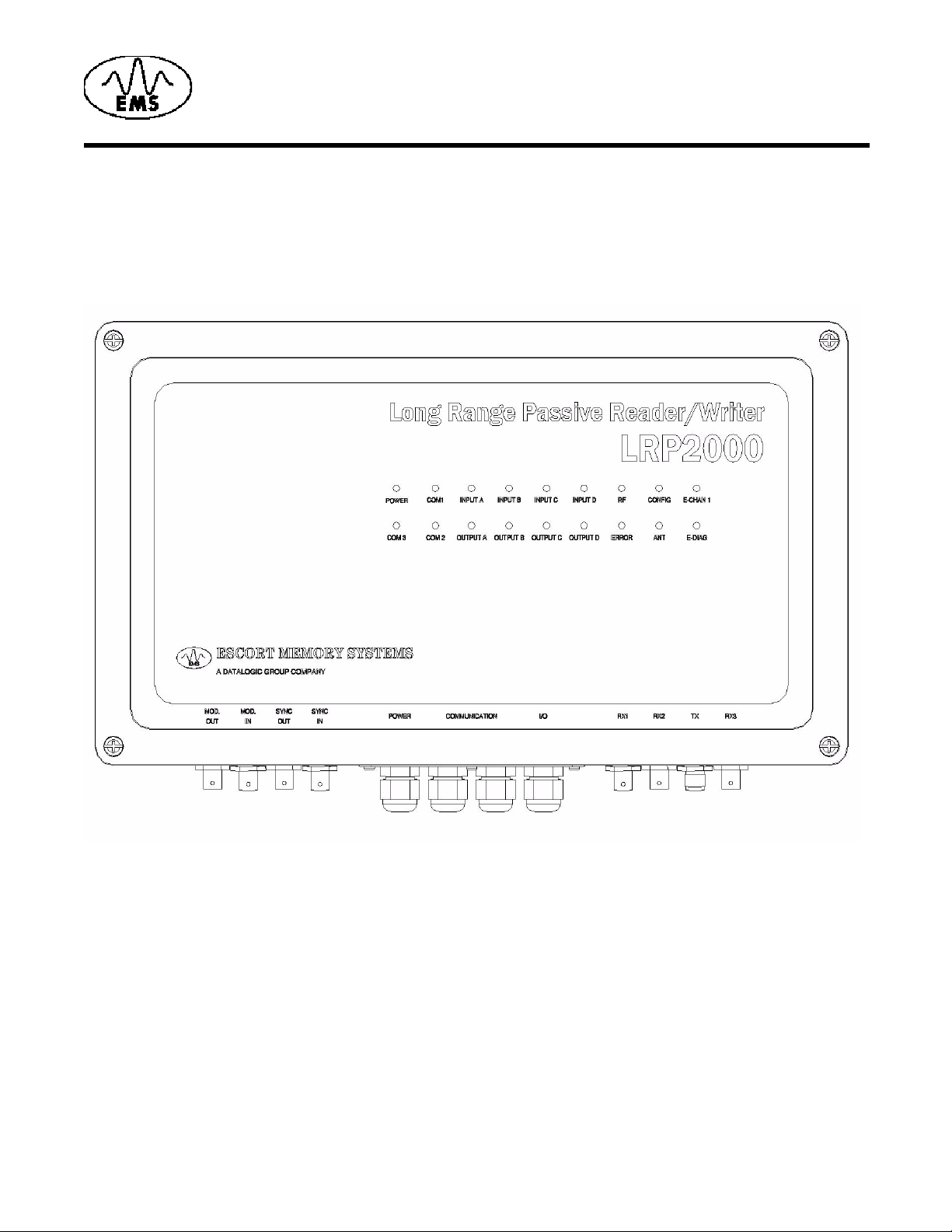
4.4 LED Indicators
The LRP2000 has 18 LED indicators conveniently located on the lid to indicate the operating status of the
controller. The locations of the LED indicators are shown in Figure 39.
43 LRP2000 Passive Reader/Writer
Page 49

Communications Interface
Figure 39: LED Indicators
Table 13: LED Indicators
LED Color Meaning
POWER RED The LRP2000 is receiving power
COM1 GREEN /
RED
INPUT A YELLOW The Input is active
INPUT B YELLOW The Input is active
INPUT C YELLOW The Input is active
INPUT D YELLOW The Input is active
RF GREEN RF data transfer
CONFIG GREEN Flashes green for 0.5 seconds to indicate the successful execution of an
E-CHAN 1 Lights solid to indicate that the Ethernet connection is idle. Blinks to
COM2 GREEN/RED RED: Incoming data on COM2 RS232 RX
COM3 GREEN/RED RED: E-Chan-1
RED: Incoming data on COM1 RS232 RX
GREEN: Outgoing data on COM1 RS232 TX and COM1 RS422 Y and Z
ABx command
indicate that the Ethernet module is connected and active
GREEN: Outgoing data on COM2 RS232 TX
GREEN: E-Diag
LRP2000 Passive Reader/Writer
44
Page 50

Communications Interface
Table 13: LED Indicators
LED Color Meaning
OUTPUT A GREEN Output A active
OUTPUT B GREEN Output B active
OUTPUT C GREEN Output C active
OUTPUT D GREEN Output D active
ERROR RED Flashes red for 0.5 seconds to indicate the unsuccessful execution of an
ANT RED Antenna is transmitting
ABx command
E-DIAG Blinks in combination with E-CHAN 1 LED to provide diagnostic
information. See explanation below.
Flashing LED Signals
Flashing LED indicators, or combinations of flashing LED indicators, are used to indicate certain controller
states, or transitions from one state to another.
ERROR LED - 4 Flashes
The ERROR LED alone flashes four times to indicate that the controller is entering the do wnload routine.
This indicates that SW5 is in the “ON” position during a power-on or hard reset. With a terminal correctly
configured and connected to COM2, the download menu is displayed.
ERROR and CONFIG LEDs - 4 Simultaneous Flashes
The ERROR and CONFIG LEDs flash simultaneously four times to indicate that (CTRL-D) has been
received within the first seven seconds of power-on or hard reset. With a terminal co rrectly con figured and
connected to COM2, the configuration menu is displayed.
ERROR and CONFIG LEDs - 4 Alternating Flashes
The ERROR and CONFIG LEDs alternately flash four times to indicate that the controller is entering
operating mode and is ready to receive commands on COM1.
E-DIAG and E-CHAN 1 Ethernet Module diagnostic codes
The E-DIAG LED lights solidly to indicate the following errors. These errors can be identified by the
number of times that the E-CHAN 1 LED blinks.
Number of
Blinks
1 EPROM Checksum Error
2 RAM Error
3 Network Controller Error
4 EEPROM Checksum Error
5 Duplicate IP address on network
6 Software does not match
Error
hardware
45 LRP2000 Passive Reader/Writer
Page 51

Communications Interface
The E-DIAG LED and the E-CHAN 1 LEDs blink at the same time to indicate the following errors:
Number of
Blinks
4 Faulty Network Connection
5 No DHCP Response Received
Error
LRP2000 Passive Reader/Writer
46
Page 52

Menu Configuration
The LRP2000 features a menu-driven program designed to give convenient access to the serial
parameters, restore defaults, or change operating modes.
5.1 How to Enter the Menu Configuration
Begin by connecting the COM2 port to your PC host (see table below) and running EC that is available on
the diskette, or from Escort Memory Systems’ Web site at www.ems-rfid.com.
LRP2000 Standard PC Serial Port
COM2 Pin Number
5TX2 RX
4RX3 TX
6 GND 5 GND
Set the serial parameters to the LRP2000 default settings or the last known state of COM2.
Signal Name DB9 Pin Number Signal Name
5
The default settings for COM2 are as follows:
• Baud- 9600
• Parity- None
• Data bits- 8
• Stop bits- 1
• Flow control- None
If you cannot establish communications with COM2, do the following to restore the default values:
1. Place DIP switch 5 in the ON position and cycle power to the LRP2000, or press the reset switch. This
loads the default values.
2. Place DIP switch 5 in the OFF position and cycle power once more.
Please refer to Chapter 4,
To enter the Main Boar d Configuratio n Menu, cycle power or press the r eset switch, and then pr ess CTRL-
D within the first seven seconds of the initialization. The LRP2000 displays the Configuration Menu . As the
LRP2000 starts the Configuration program, both the RF and CONFIG LEDs flash. The Main Board
Configuration Menu displays with the current main board software version number together with the DSP
firmware version.
*****************************************************
LRP2000 (ISO Only) Standard Program
Main Program V0.5D, Sept. 2002
DSP Program V0.5c, November 2002
*******************************************************
[1] Set-up Operating Parameters
[2] Download New Program
[3] Download DSP Program
[4] Exit to Operating Mode
Enter Selection:
Communications Interface for more information on the serial interface.
LRP2000 Passive Reader/Writer 47
Page 53

5.2 Set-Up Operating Parameters
To change the operating parameters of the LRP2000, enter 1 at the initial menu.
The following menu is displayed, listing the current settings (the exact appearance of the menu display
depends on the settings you have made and will be updated when you save your changes):
Serial Port COM1: RS232, 9600, N, 8, 1, No handshake (DIP switches)
Serial Port COM2: RS232, 9600, N, 8, 1, No handshake
Command Protocol: ABx Standard
RF Communication: Fast Mode
[1] Set COM1 Parameters
[2] Set COM2 Parameters
[3] Set Operating Mode
[4] Set RF Communications
[5] Restore Factory Defaults
[6] Return to Main Menu
Enter Selection:
Enter the number of the sub-menu you wish to enter. When you have made your selection, you are
prompted to save your changes to the non-volatile EEPROM. For the new settings to take effect, you must
save your changes to the EEPROM and reset the LRP2000. If you do not save changes to the EEPROM,
the new settings are effective only until the LRP2000 is reset.
Menu Configuration
The following sub-menus are presented here in their entirety. Actually the menus are presente d one option
at time, advancing as you enter selections. Some options shown are dependent on earlier selections.
5.2.1 Set COM1 Parameters
Selecting 1 from the above menu displays the following options for the COM1 parameters. These settings
are valid only if you are not using the DeviceNet Interfaces (such as DIP switch 4 is in the OFF position).
Enter the appropriate number at each prompt. The default values are indi cated by an asterisk (*).
*** Set COM1 Parameters ***
Baud Rate? [0] 1200 [1] 2400 [2] 4800 [3] 9600* [4] 19200 [5] 38400
Data size? [0] 7 bit [1] 8 bit*
Parity? [0] None* [1] Even [2] Odd
Handshake? [0] None* [1] Xon/Xoff
Save Changes to EEPROM? [0] No [1] Yes
5.2.2 Set COM2 Parameters
Selecting 2 from the “[1] Set-up Operating Parameters” menu displays the following optio ns for COM2.
Enter the appropriate number at each prompt. The default values are indicated by an asterisk.
*** Set COM2 Parameters ***
Baud Rate? [0] 1200 [1] 2400 [2] 4800 [3] 9600* [4] 19200
Data size? [0] 7 bit [1] 8 bit*
Parity? [0] None* [1] Even [2] Odd
Handshake? [0] None* [1] Xon/Xoff
Save Changes to EEPROM? [0] No [1] Yes
LRP2000 Passive Reader/Writer
48
Page 54

Menu Configuration
5.2.3 Set Operating Mode
The “[3] Set Operating Mode” menu allows you to choose the ABx command protocol the LRP2000 uses,
or configures it to enter Continuous Read Mode automatically upon start-up.
*** Set Operating Mode ***
Operating Mode? [0] ABx Standard* [1] ABx Fast [2] ABx ASCII
Framing Editing (for ABx Fast and ABx ASCII selection only from previous menu choice, see note below for additional setup
information).
Checksum? [0] Disabled* [1] Enabled
Power up in Continuous Read Mode? [0] NO [1] Single Tag [2] Multiple Tag
Start Address (0 to 47)
Length (1 to 48)
Delay Between Duplicate Decodes (0 to 60)
Raw Read Response? [0] NO [1] CR terminate [2] CR/LF terminate
Save Changes to EEPROM? [0] No [1] Yes
Operating Mode
The LRP2000 offers three modes for the transfer of data and commands. ABx Standard (ABxS) uses only
the LSB for tag data, while ABx Fast (ABxF) uses both the MSB and LSB for the passing of data. ABx
ASCII (ABxA) mode permits RFID operations using seven-bit data packets in the form of printable ASCII
characters.
1
Framing Editing
If option 1 “ABx Fast” or option 2 “ABx ASCII” is chosen from “Operating Mode” above, you have the option
of modifying the packet header and terminator characters. This can be useful when interfacing with other
Host devices that require the terminator to be a CR “0Dh.” The current preamble and terminator will be
displayed.The default values are 02h 02h as the p acket heade r, and 03h as a single terminating char acter.
These are the values used in command and response examples throughout this Operator’s Manual, but
can be changed to fit your needs. To use the current message framing, simply answer NO.
Current FAST Packet Framing
Preamble = 02H 02H
Terminator = 03H
Modify FAST packet framing? [0] No [1] Yes
OR
Current ASCII Packet Framing
Preamble = 02H 02H
Terminator = 03H
Modify ASCII packet framing? [0] No [1] Yes
If the YES option is selected the following prompt appears asking whether the packet should have a oneor two-character header.
Number characters in packet preamble? [1] One [2] Two
If a one-character preamble is desired, you ar e pr om p te d to en te r th e he xa de cim a l value of the cha ra ct er
in the range of 01h to 7Fh. The value 0 is illegal and cannot be used for the message preamble.
New FAST Header Character (01 - 7F) =
1. Valid ranges for Start Address and Length depend on the tag category.
49 LRP2000 Passive Reader/Writer
Page 55

Menu Configuration
If a two-character preamble is desired, you are prompted to enter the hexadecimal value of both
characters. The prompts shown below are if ABx Fast protocol was selected. If ABx ASCII protocol was
selected, the prompts will reflect that.
First FAST Header Character (01 - 7F) =
Second FAST Header character (01 - 7F0) =
Once the preamble character(s) have been entered, the following prompt appears allowing the user to
specify one- or two-character message termination sequence.
Number characters in packet termination? [1] One [2] Two
If a one-character terminator is desired, you are prompted to enter the hexadecimal value of the character
in the range of 01h to 7Fh. The value 0 is illegal and cannot be used for the message terminator.
New FAST terminator Character (01 - 0F) =
If a two-character preamble is desired, you are prompted to enter the hexadecimal value of both
characters. The prompts shown below are if ABx Fast protocol was selected. If ABx ASCII protocol was
selected, the prompts will reflect that.
First FAST Terminator Character (01 - 7F) =
Second FAST Terminator Character (01 -7F) =
At this point the selection returns to the main menu.
Checksum? [0] Disabled [1] Enabled
After the checksum prompt, the following prompt appea rs allowin g yo u to co nf igu re the LRP con tr oller to
begin scanning for tags at power-up automatically:
Power up in Continuous Read mode?
[0] NO
[1] Continuous Block Read (0Dh) active
[2] Continuous Block Read All (8Dh) active
[3] Continuous SN Block Read All (83h) active
If option 1 (Continuous Block Read) is selected, the following prompts appear to allow you to specify the
starting tag address, how many seconds the tag must be out of the RF field before it is read again, and
what the Raw Read Response should be:
Start Address (0 to 111)
1
Length (1 to 112)
Delay Between Duplicate Decodes (0 to 60)
Raw Read Response? [0] NO [1] CR terminate [2] CR/LF terminate
1. Valid ranges for Start Address and Length depend on the tag category.
LRP2000 Passive Reader/Writer
50
Page 56

Menu Configuration
If option 2 or 3 is selected from the “Power Up In Continuous Read Mode ” me n u, the fo llow i ng prom pts
appear to allow you to specify the starting tag address, how many bytes will be read, the Family Code
subset of tags to be read, the number of different tags that must be seen before the same tag will be read
again, and what the Raw Read Response should be:
Start Address (0 to 111)
Length (1 to 112)
Family Code
Tag Delay (0 to 225)
Raw Read Response? [0] NO [1] CR terminate [2] CR/LF terminate
Power up in Continuous Read Mode?
You also have the option of setting the LRP2000 to start up in Continuous Read Mode. When you have
configured the LRP2000 to function in this manner, you do not issue commands to the LRP2000. It will,
upon start up, enter directly into a Continuous Read Mode. Since this bypasses the normal command
parameters, you must specify the Continuous Read Mode parameters.
The LRP2000 responds to other commands and resumes Continuous Read Mode when completed.
If you are using your LRP2000 in this mode, you must choose whether you want the LRP2000 to read a
single tag or multiple tags within the field.
To exit Continuous Read Mode, you must either re-enter the Configuration Menu and select NO from the
Power up in Continuous Read Mode option, or issue a Continuous Read command from the host with a
length of 0 as described in Chapter 6, RFID Interface.
Start Address (0-XXX)
Enter the tag address where you want the re ad to begin.
Length (1-XXX)
Enter the length of the read you wish the LRP2000 to perform. Make certain that the length value does not
exceed the number of possible addresses following the starting tag address. Entering a read length of 0
disables Continuous Read Mode.
Delay Between Identical Decodes (0-60)
The Delay Between Identical Decodes parameters can have a value of 0 to 60 seconds. When the Delay
Between Identical Decodes is set to 0, the LRP2000 continuously reads AND transmits tag data to the
host. This can flood the buffers and cause communication errors and data loss.
Raw Read Response?
If you have selected ABx Fast or ABx ASCII, you have the option of stripping the command protocol from
the data and adding a terminator to separate the data packets. You can choose a CR (0DH) or CR/LF
(0DH, 0AH) to terminate the data.
51 LRP2000 Passive Reader/Writer
Page 57

5.2.4 Set RF Communication
*** Set RF Communication ***
RF Communication
Enter Tag Category
Save Changes to EEPROM
RF Communication
Fast Mode or Standard Mode sets the RF data rate from the read er to the tag and should be set to the
default condition “Fast Mode.” Standard Mode was implem ented to meet strict ce rtification emission limits,
which is not needed in most countries.
***RF Communication? ***
RF Communication? [0] Fast Mode* [1] Standard Mode 0
Enter Tag Category
The LRP2000 support ISO15693 tags. The LRP2000 allows you to specify Philips, Infineon, or Texas
Instruments tags. Specifying a tag type allows the LRP2000 to understand the memory organization,
features, and performance of the tag being used. Only one manufacturer’s tags can be used in an
installation.
***Enter Tag Category***
Enter Label Type: [1] SLI, [2] Tag-it, [3] My-D
Menu Configuration
Save Changes to EEPROM
Saving the changes to EEPROM makes the configuration setting permanent. Otherwise when the power is
cycled the configuration setting returns to the previous setting.
***Save Changes to EEPROM***
Save Changes to EEPROM? [0] No [1] Yes
5.2.5 Restore Factory Defaults
It is often helpful during troubleshooting to restore the LRP2000 to known default values. To do so, select 1
from this menu:
*** Restore Factory Defaults ***
Restore Factory Default? [0] No [1] Yes
The restored defaults are saved to the EEPROM. The communication defaults can also be restored by
placing the main board DIP switch 5 in the ON position and then restarting the LRP2000. After you have
saved any changes, you must re-initialize the LRP2000 with switch 5 in the OFF position.
5.2.6 Return to Main Menu
When you have completed your configuration, entering 5 returns you to the initial menu. Unsa ved changes
are effective until the LRP2000 is reset. Saved changes are loaded automatically the next time the
LRP2000 is reset.
LRP2000 Passive Reader/Writer
52
Page 58

Menu Configuration
5.3 Download New Program
Before attempting to download new firmware to the LRP2000 main board, read the instructions provided in
a readme.txt file on the update diskette.
When you select 2 from the Main Menu, the LRP2000 displays information on the current program and
prompts you to begin the download.
*** Download New Program***
Program Size: 21824 Bytes
Program Checksum: 5AE0H (OK)
Free Program Memory: 39600 Bytes
Flash Write Counter: 2 times
Press a key to start Downloading
After you have pressed a key, the LRP2000 displays:
Send the Intel Hex file. Downloading now.
Send the new program file via your terminal emulation program in ASCII text or hexadecimal format. Wait
10 seconds after the download is complete before resetting the LRP2000.
NOTE: It is not necessary to download firmware into the unit unless you are instructed to do so by Escort
Memory Systems technical support personnel.
5.4 Downloading DSP Firmware
Before attempting to download new firmware to the LRP2000 main board, read the instructions provided in
a readme.txt file on the update diskette.
When upgrading software in the controller, the number and meaning of the configuration parameters may
not match between the old and new software. The old settings may not be interpreted properly with the
new software. Before downloading another version of software, display and record the current
configuration settings, then download the new software version.
Set DIP switch 5 (on the main board) ON and apply power to initialize the configuration parameters to their
default states. When the LEDs stop flashing, turn DIP switch 5 to OFF and press the reset switch. Enter
the Configuration Menu and re-enter any non-default configuration parameters.
When you select 3 from the Main Menu, the LRP2000 prompts you to begin the download.
*** Download DSP Program***
Press a key to start Downloading
After you have pressed a key, the LRP2000 displays:
Send the Intel Hex file. Downloading now.
53 LRP2000 Passive Reader/Writer
Page 59

Send the new firmware via your terminal emulation program in ASCII text or hexadecimal format. The
firmware is automatically transferred to the DSP Flash Memory. Wait 10 seconds after the download is
complete before resetting the LRP2000.
Record: 750
Download OK
File Transfer to DSP
Block 24/24
DSP Flash Programming...
New Firmware Transferred to DSP
WARNING: Do not download INTERFACE BOARD firmware to the main board.
NOTE: It is not necessary to download firmware into the unit unless you are instructed to do so by Escort
Memory Systems technical support personnel.
5.5 Exit to Operating Mode
This option is available if you wish to use temporary, unsaved, configuration parameters. The unsaved
options you have selected are used until the LRP2000 is reset and the saved parameters are restored.
Menu Configuration
LRP2000 Passive Reader/Writer
54
Page 60

6.1 Introduction
Conventions
In this manual, numbers expressed in hexadecimal are appended with “H.” For example, the decimal
number 10 is expressed as “0AH” in hexadecimal. The addresses of the bytes of read/write memory within
an RFID tag are numbered from 0 to N, where N is one less than the numb er of read/write b ytes in the t ag.
The number of read/write bytes is equal to the Block Size multiplied by the Number of Blocks.
Command protocols
The LRP2000 offers three possible command protocols: ABx Standard, ABx Fast, and ABx ASCII. The
commands in all three protocols have the same basic structure. RFID Command protocols do not affect
the LRP2000 to tag communications.
ABx Standard is a word-based format and shares a common syntax with most existing RFID systems
produced by Escort Memory Systems. ABx Standard was designed for PLCs that hand le word-ba sed dat a
better then byte-based data.
6
RFID Communications
The ABx Fast and ABx ASCII protocols are byte-based packet structures. ABx Fast permits command
execution with fewer total bytes transferred. Escort Memory Systems recommends ABx Fast with
checksum enabled because of faster command execution and increased error detection.
Commands are comprised of a header, a number of parameters, an d a command termin ator. The headers
and terminators are unique to each protocol, but a re the same for every comman d within one protocol. For
example, in ABx St anda rd, every command begins with th e one-byte heade r “AAH,” and end s with the twobyte terminator “FFFFH.” In ABx Fast and ABx ASCII, every command begins with the 0202H, and ends
with 03H for the default configuration setting. The header and terminator can be changed in the
configuration settings menus.
Like the commands, the responses from the co ntr o ller com pr ise a heade r, a number of response codes
and data, and a response terminator . The headers and terminators are the same for the re sponses as they
are for the commands. The ABx command set is made of three subsets: the single-t ag commands, multitag commands, and user I/O commands. The sing le-tag commands perform read/write operations on
exactly one tag in the range of the antenna at a time. The presence of more than one tag within the range
of the antenna may cause RFID communication errors. To avoid these errors, the multi-tag commands
allow for simultaneous communication to and from multiple tags within the reading range of the antenna.
The user I/O commands do not communicate with RFID tags. They simply interrogate the status of the
inputs wired to the unit, and set the status of the outputs.
LRP2000 Passive Reader/Writer 55
Page 61

6.1.1 ABx Command Set Listings
Table 14, Table 15, and Table 16 list the ABx commands recognized by the LRP2000.
Table 14: Single Tag Commands
04H Fill Tag
05H Read
06H Write
07H Read Tag Serial Number
08H Tag Search
0DH Continuous Read
14H Get Status
16H Write Family Code
17H Lock Family Code
94H SN Fill
95H SN Read
RFID Communications
96H SN Write
Table 15: Multi-tag Commands
82H SN Read All
83H Start/Stop Continuous SN Read All
84H Fill Tag All
85H Read All
86H Write All
87H Read Tag SN All
88H Tag Search All
8BH Write Family Code All
8CH Lock Family Code All
8DH Start/Stop Continuous Read All
91H Memory Lock All
Table 16: User I/O Commands
10H Set Output
11H Input Status
NOTE: The delay between the characters of a command sent to the controller cannot be longer than
200 ms.
LRP2000 Passive Reader/Writer
56
Page 62

RFID Communications
6.2 Command Parameters
6.2.1 Command Timeout
All single-tag and multi-tag commands have a timeout value that is used to specify the time the controller
will attempt to complete the specified operation. The absolute minimum timeout value that can be issued to
the controller is 1 millisecond. The absolute maximum time for which the controller will attempt to complete
a command is just over one minute. The timeout parameter is passed to the controller in units of
milliseconds with a maximum value of 65,534 (FFFEH) milliseconds. A timeout value of 0 will generate a
syntax error. Thirty milliseconds is the shortest recommended timeout and should only be used for singletag command applications. Multiple-tag commands will require longer timeout values. For applications
where the time that the tags spend in the field must be short, tests should be performed to ensure that a
sufficiently large timeout value is chosen in order to read all of the tags. A longer timeout value does not
necessarily mean that a command will take any longer to execute. If the tags being addressed are in the
field, it only represents the period of time (in milliseconds) the unit will attempt to execute the command. If
the tags are present, the response time to execute the command will be the same whether the timeout is
100 ms or 10,000 ms.
6.2.2 Delay Between Duplicate Decodes
The one parameter that is unique to the single-tag command 0DH is Delay Between Duplicate Decodes.
After S tart/S top Con tinuous Read is starte d, any tag that come s within range of the antenna is read and the
requested data from the tag is sent to the host. This delay parameter represents the number of seconds
that a tag must remain out of range before it is read a second time. This de lay is implemented to allow you
to limit the volume of information sent by the controller. With this delay parameter set to 00H, the controller
repeatedly sends the requested informa tio n until the tag is out of range . Th e ma xim u m allo wa ble v alue is
60 (3CH) seconds.
6.3 Multi-tag Command Parameters
6.3.1 Tag Repeat Count
The Tag Repeat Count allows you to limit the volume of information sent by the controller when you are
using the multi-tag Continuous Read commands, 83H and 8DH. Af ter Continuous Read is initiated, an y tag
that comes within range of the antenna is read, and the requested data from the ta g is sent to the host. The
Tag Repeat Count parameter represents the number of other tags that must be read before the data from
the first tag is sent for a second time.
This feature uses a FIFO overflow buffer; first tag in will be the first tag id to be discarded when the buffer
is full. Every time a tag is read its ID is compared to the cur rent buff er to see if it has been read befor e. The
value you use for the tag count is directly related to the buffer size. Tags are read once upon entering the
field, and read a second time only after they have been reset by leaving and re-entering the field. Once a
tag reenters the field, it is read again and compar ed to the buffer. If the tag ID is not in the buffer, the tag
data requested is sent to the host. If the tag ID is in the buffer, it is ignored by the LRP2000.
With this Count parameter set to 00H, the controller repeatedly sends the requested information until the
tags are out of range.
6.3.2 Family Codes
Family Codes allow you to organize the tags in your application. For example, you can use one family code
for pallet identification, a second family code for case-level identification, and a third family code for itemlevel identification. With the tags organized by family code this way, you could read a box of tagged items
on the assembly line with item level family codes, and then write the product code and quantity to a case
level tag.
57 LRP2000 Passive Reader/Writer
Page 63

At the pallet level, a read command of the case level family coded tags would produce the quantity of
cases on the pallet and the case data and the quantity of cases could be written to the pallet tag using the
pallet tag family code. This way a pallet going through a gate can be read quickly by just reading the pallet
family codes and ignoring the case and item level family coded t ags. Or if quantity verification is required, a
more time consuming read of case level or even item level can be issued.
The multi-tag commands always have a Family Code as a parameter. The Family Code is a one-byte field
in the tag, which resides outside the read/write memory address space. When the Family Code parameter
is set to 0, all the tags in the field will respond. When the Family Code parameter is set to a non-zero byte
value, only tags with the same specified Family code will respond. The Family Code byte can be read,
written, and locked independently of the rest of the read/write address space in the tag.
6.3.3 Start Continuous Read
This parameter, included only on command 83H, is a one-byte parameter that starts the Continuous Read
if set to 01H, and stops the Continuous Read if set to 00H. Both of the other Continuous Read
commands— 0DH and 8DH—rely on the Number of Bytes to be read to start and stop the command. If the
Number of Bytes is set to any valid nonzero value, the Continuous Read starts. If it is set to zero, the
Continuous Read stops. The use of this additional parameter on command 83H allows for the Number of
Bytes to be set to zero upon initiation of the command, thereby interrogating the tags only for their serial
numbers.
RFID Communications
CAUTION:EMS recommends that before issuing other commands, you always issue a Stop Continuous
Read command, and then issue a Start Continuous Read after the interim command has been
executed. Applications that send other commands during Continuous Read mode should be
thoroughly tested before deployment.
LRP2000 Passive Reader/Writer
58
Page 64

RFID Communications
6.4 Standard ABx Protocol
The ABx standard is a binary protocol, word (2-byte) oriented, so the syntax table reports the most
significant byte (MSB) and the least significant byte (LSB). In the serial transmission, the MSB is
transmitted first.
Table 17: Single Tag Example
Field
Header 1 AAH
Command 1 Command Code
Start Address 2 One word gives the first byte of tag memory to be accessed
Number of Bytes 2 One word gives the number of contiguous bytes to be accessed. Not used on 07H,
Block Addresses 2 The first byte gives the address of the first block. The second byte gives the
Timeout 2 0001H to FFFEH milliseconds
Data varies Data that is written to a tag. Each byte is included in the LSB of a two-byte word
Terminator 2 FFFFH
Number
of Bytes
Content
08H, 14H, 16H
number of blocks to be interrogated. Only used with command 14H
Table 18: Multi-tag Example
Field
Header 1 AAH. Always the MSB of the first word of an ABX Standard command
Number
of Bytes
Content
Command 1 Command Code - LSB of the first word
Family code 1 00H to address all tags in field
Reserved 1 Reserved for future use, set to 00H
Start Address 2 One word gives the first byte of tag memory to be accessed
Number of Bytes 2 One word gives the number of contiguous bytes to be accessed. Not used on
Block Addresses 4 The first word gives the address of the first block. The second word gives the
Timeout 2 0001H to FFFEH milliseconds
Data varies Data that is written to a tag. Each byte is included in the LSB of a two-byte word.
Terminator 2 FFFFH
commands 87H, 88H, 91H, 8BH, 8CH
number of blocks to be interrogated. Only used with command 91H
59 LRP2000 Passive Reader/Writer
Page 65

6.4.1 ABxS Command 04H: Fill Tag
DESCRIPTION
Fill an RFID tag with a one-byte value over multiple contiguous addresses.
DISCUSSION
This command is commonly used to clear contiguous segments of a tag's memory. It writes a one-byte
value repetitively across a specified range of tag addresses. The fill function requires one data value byte,
a starting address, and a fill length. It fills the tag with the data value byte, starting at the specified start
address for the specified number of consecutive bytes. When Fill Length is set to 0, the controller writes fill
data from the start address to the end of the tag's memory. The timeout value is given in 1 ms increments
and can have a value of 001EH to FFFEH (65,534 m s). W hen the time out is set to 0, the controller r eturns
a syntax error.
Field Remarks
Command Command number in hex preceded by AAH
Start Address Tag address where the fill starts
Fill Length Number of tag addresses to be filled in bytes
Timeout Timeout value given in 1 ms units (1EH - FFFEH)
Data Value Byte Byte to be used as fill
Message Terminator FFFFH
RFID Communications
Example
The goal is to write ASCII 'A' (41H) to the ten bytes of tag memory starting at byte address 5. A timeout of
2 seconds (07D0H = 2000 x 1 ms increments) is set for the completion of the command.
Command from Host Successful Response From Controller
MSB LSB Remarks MSB LSB Remarks
AAH 04H Perform Command 4 AAH 04H Command Echo
00H 05H Start Address = 0005H FFH FFH Message Terminator
00H 0AH Fill Length= 10 bytes(000AH)
07H D0H 2-second Timeout
00H 41H Data Value Byte = 41H
FFH FFH Message Terminator
LRP2000 Passive Reader/Writer
60
Page 66

RFID Communications
6.4.2 ABxS Command 05H: Read
DESCRIPTION
Read data from contiguous bytes of the RFID tag's read/write memory.
DISCUSSION
This command is used to read bytes from contiguous areas of tag memory. The minimum length of the
data read from the tag is 1 byte. The maximum is the entire read/write address space of the tag. The
timeout value is given in 1 ms increments and can have a value of 001EH to FFFEH (65,534 ms). When
the timeout is set to 0, the controller returns a syntax error. The Read command consist s of a sta rt address
and length, followed by the message terminator, FFFFH, as shown below. If the read range exceeds the
last tag address, the controller returns error message 21H, invalid format. The data read from the tag is
returned in the least significant byte (LSB) of the word, and the most significant byte (MSB) is always 00H.
Field Remarks
Command Command number in hex preceded by AAH
Start Address Tag address where the read starts
Read Length Number of tag addresses to be read
Timeout Timeout value given in 1 ms units (001EH - FFFEH)
Message Terminator FFFFH
Example
The goal is to read the eight bytes of data from the tag starting at address 1. A timeout of 2 seconds
(07D0H = 2000 x 1 ms increments) is set for the completion of the Read.
Command From Host Response from Controller
MSB LSB Remarks MSB LSB Remarks
AAH 05H Perform Command 5 AAH 05H Command Echo
00H 01H Start Byte Address = 0001H 00H 52H Read Data 1 =52H
00H 08H Read Length = 8 bytes 00H 46H Read Data 2 =46H
07H D0H 2-second Timeout 00H 49H Read Data 3 =49H
FFH FFH Message Terminator 00H 44H Read Data 4 =44H
00H 20H Read Data 5 =20H
00H 54H Read Data 6 =54H
00H 61H Read Data 7 =61H
00H 67H Read Data 8 =67H
FFH FFH Message Terminator
61 LRP2000 Passive Reader/Writer
Page 67

6.4.3 ABxS Command 06H: Write
DESCRIPTION
Writes data to an RFID tag.
DISCUSSION
This command is used to write segments of data to contiguous areas of tag memory. It is capable of
transferring up to 112 bytes of data transferred from the Host with one command. The timeout value is
given in 1 ms increments and can have a value of 001EH to FFFEH (65,534 ms). When the timeout is set
to 0, the controller returns a syntax error. The Write command consists of a start address followed by the
data stream to be written to the RFID tag. If the write range exceeds the last tag address, the controller
returns error message 21H, invalid format. The controller returns an error if the write length is 0. The data
to be written to the tag is contained in the LSB of the register, and the MSB is always 00H.
Field Remarks
Command Command number in hex preceded by AAH
Start Address Tag address where the write will start
Write Length Number of tag addresses to be written to in bytes
Timeout Timeout value given in 1 ms units (001EH - FFFEH)
Write Data Data to be written
Message Terminator FFFFH
RFID Communications
Example
Writes 4 bytes of data to the tag sta rting at addre ss 0020H. A timeou t of 2 seconds (07D0H = 2000 x 1 ms
increments) is set for the completion of the Write.
Command from Host Response from Controller
MSB LSB Remarks MSB LSB Remarks
AAH 06H Perform Command 6 AAH 06H Command Echo
00H 20H Start Address = 0020H FFH FFH Message Terminator
00H 04H Write Length = 4 bytes
07H D0H 2-second Timeout
00H 52H Write Data 1 =52H
00H 46H Write Data 2 =46H
00H 49H Write Data 3 =49H
00H 44H Write Data 4 =44H
FFH FFH Message Terminator
LRP2000 Passive Reader/Writer
62
Page 68

RFID Communications
6.4.4 ABxS Command 07H: Read Tag Serial Number
DESCRIPTION
This command retrieves the eight-byte tag serial number.
DISCUSSION
Each controller tag has a unique serial number. This number cannot be changed and is not part of the
available data bytes. The tag serial number is returned in the LSB only, with the MSB as 00H.
Field Remarks
Command Command number in hex preceded by AAH
Timeout Timeout value given in 1 ms units (001EH - FFFEH)
Message Terminator FFFFH
Example
In this example, the LRP 2000 waits u ntil a tag is in range and then reads the eight- byte serial number. The
ID is AC310200000104E0H (hexadecimal) in this example.
Command from Host Response from Controller
MSB LSB Remarks MSB LSB Remarks
AAH 07H Perform Command 7 AAH 07H Command Echo
07H D0H 2-second Timeout 00H ACH First SN byte
FFH FFH Message Terminator 00H 31H Second SN byte
00H 02H Third SN byte
00H 00H Fou rth SN byte
00H 00H Fifth N byte
00H 01H Sixth SN b yte
00H 04H Seventh SN byte
00H E0H Eighth SN byte
FFH FFH Message Terminator
63 LRP2000 Passive Reader/Writer
Page 69

6.4.5 ABxS Command 08H: Tag Search
DESCRIPTION
Check to see if there is an RFID tag in the antenna field.
DISCUSSION
This command activates the controller to search for the presence of a tag within range of the antenna. If
the controller finds a tag, it returns a command echo to the host. The timeout value is given in 1 ms
increments and can have a value of 001EH to FF FEH (30 to 65 ,534 ms). Whe n the timeou t is set to 0 , the
controller returns a syntax error. If no tag is present, it returns an err or messa ge. See Section 6.2 for mor e
information on error codes.
Field Remarks
Command Command number in hex preceded by AAH
Timeout Timeout value given in 1 ms units (001EH - FFFEH)
Message Terminator FFFFH
Example
Checks for an RFID tag in the RF field. A timeout of 2 seconds (07D0H = 2000 x 1 ms incr ements) is set for
the completion of the Tag Search.
RFID Communications
Command from Host Response from Controller
MSB LSB Remarks MSB LSB Remarks
AAH 08H Perform Command 8 AAH 08H Command Echo
07H D0H 2-second Timeout FFH FFH Message Terminator
FFH FFH Message Terminator
6.4.6 ABxS Command 0D H: Stop/Start Continuous Read
DESCRIPTION
When in Continuous Read mode, the controller sends rea d command s con ti nuously to a ny tag in range of
the antenna. When a tag comes within range, it is read and the data passed to the host computer. The
controller continues to read the tag but does not send the same data to the host until the tag has been
outside the RF field for a specified time period. This Delay Between Identical Decode s par ameter prevent s
redundant data transmissions when the controller is in Continuous Read mode.
DISCUSSION
The Start/Stop Continuous Read command contains three parameters: read length, start address, and
delay between identical decodes. The read length parameter switches the mode. Any valid, non-zero
length (1-48) sets the controller into Continuous Read mode. A read length value of 00H tu rns Contin uous
Mode off. The Delay Between Identical Decodes parameters can have a value of 0 to 60 seconds. When
the Delay Between Identical Decodes is set to 0, the controller continuously reads AND transmits tag data
to the host. This can flood the buffers and cause communication errors and data loss. If the controller
receives other commands from the host, it executes them and then resumes Continuous Read mode. To
exit Continuous Read mode, issue the command with a read length of 0.
LRP2000 Passive Reader/Writer
64
Page 70

RFID Communications
In Continuous Read mode, the LEDs indicate the following:
LED Behavior Description
ANT ON Assumes the antenna is powered and functioning
CONFIG BLINK Tag entered the RF field
RF ON Tag has been read and is still in the field
RF OFF Read tag has been out of range for the specified time
The command and response from the controller are formatted as follows.
Command Response
Field Remarks MSB LSB Remarks
Command Command number in hex preceded by AAH AAH 0DH Command Echo
Start Address 2 byte value for the start address in the tag FFH FFH Message Terminator
Read Length 2 byte value for the read length
Delay Between
Identical Decodes
Message Terminator FFFFH
Time the tag must be out of the antenna range before
the controller will transmit data again from that tag.
Value is expressed in 1 second units
This example places the controller in Continuous Read mode and reads eight bytes of data from the tag
starting at address 0001H. A delay between identical reads of 2 seconds (0002H =2 x 1 second
increments) is set.
Command from Host Response from controller
MSB LSB Remarks MSB LSB Remarks
AAH 0DH Perform Command D AAH 0DH Command Echo
00H 01H Start address 00H 52H Read data byte 1
00H 08H Read 8 bytes 00H 46H Read data byte 2
00H 02H 2-second Timeout 00H 49H Read data byte 3
FFH FFH Message Terminator 00H 44H Read data byte 4
00H 41H Read data byte 5
00H 20H Read data byte 6
00H 54H Read data byte 7
00H 61H Read data byte 8
FFH FFH Message Terminator
The controller first returns an acknowledgment of the command followed by a response containing read
data when a tag enters the antenna fiel d.
65 LRP2000 Passive Reader/Writer
Page 71

To exit Continuous Read mode , sen d the comman d with th e read leng th vari able se t to 0 as sh own below.
The value of the other variables are not considered.
Command from Host Response from Controller
MSB LSB Remarks MSB LSB Remarks
AAH 0DH Perform Command D AAH 0DH Command Echo
00H 01H Record Length FFH FFH Message Terminator
00H 00H Read 0 bytes/end mode
00H 02H 2-second Timeout
FFH FFH Message Terminator
6.4.7 ABxS Command 14H: Get Memory Status
DESCRIPTION
Returns the lock status of the specified blocks of data.
DISCUSSION
This command can be used to determine whether blocks of tag memory are locked (marked “read-only”).
The number of specified contiguous blocks are addressed from the specified first block. The r esponse from
the controller gives the status of each block through a one-word value. The value is 0000H if the block is
unlocked, 0001H if locked.
RFID Communications
Field Content
Header AAH
Command 14H
First Block Two-byte value for the first block whose lock status will be interrogated
Number of blocks Two-byte value for the number of blocks whose lock status will be interrogated
Timeout Timeout value given in 1 ms units (001EH - FFFEH)
Message T erminator FFFFH
Response from controller:
Field Content
Header AAH
Command Echo 14H
Status One word represents the status of each block 0000H indicates that the block is not
locked 0001H indicates that the block is locked
Terminator FFFFH
LRP2000 Passive Reader/Writer
66
Page 72

RFID Communications
6.4.8 ABxS Command 16H: Write Family Code
DESCRIPTION
Changes the family code of an RFID tag.
Field Content
Header AAH
Command 16H
Timeout Timeout value given in 1 ms units (001EH - FFFEH)
New Family Code One word with 00H in the MSB and the new Family Code in the LSB
Terminator FFFFH
Response from controller:
Field Content
Header AAH
Command Echo 16H
Terminator FFFFH
6.4.9 ABxS Command 17H: Lock Family Code
Description:
Locks the Family Code Byte to its current value, so that it cannot be written. Once locked, the Family Code
cannot be unlocked.
Field Content
Header AAH
Command 17H
Timeout Timeout value given in 1 ms units (001EH - FFFEH)
Terminator FFFFH
Response from controller:
Field Content
Header AAH
Command Echo 17H
Terminator FFFFH
67 LRP2000 Passive Reader/Writer
Page 73

6.4.10 ABxS Command 82H: SN Read All
DESCRIPTION
Command 82H reads the serial numbers and the specified bytes of data from all RFID tags in the field or
those with the specified Family ID. Returns the serial number of the tags read, along with tag data.
DISCUSSION
This command is used to read segments of data from contiguous areas of tag memory. It is capable of
transferring the entire read/write address of data transferred to the host with one command. The timeout
value is given in 1 ms increments and can have a value of 001EH to FFFEH (65,534 ms). When the
timeout is set to 0, the controller returns a syntax error.
The response to this command conta ins the se ria l nu mb e r o f th e r espondin g tags preceding the data from
those tags. The termination packet is transmitted when the timeout expires. Each p acket is sent to the host
as soon as it is available. The returned serial numbers can be used to read and write to tags in the field via
the SN Read/Write command.
The SN Read All consists of Family ID, Reserved Byte, a start address and length, followed by a timeout
value, and the message terminator , FFFFH. A special termination p acket is sent when the timeout expires.
If the read length exceeds the last tag address, the controller returns a syntax error, code 21H.
Field Remarks
Command Command number in hex preceded by AAH
Tag Family Tag Family ID - 00H = all tags
Reserved 00H
Start Address Tag address where the read will start
Read Length Numbers of tag addresses to be read
Timeout Timeout value given in 1 ms units (001EH - FFFEH)
Message Terminator FFFFH
RFID Communications
LRP2000 Passive Reader/Writer
68
Page 74

RFID Communications
Example
Reads two bytes of data from the tag starting at address 0001H. A timeout of 2 seconds (07D0H = 2000 x
1 ms increments) is set for the completion of the SN Read All. The Family ID byte is set to zero, so all tags
will be read. Two tags respond with read data.
Command from Host Response from Controller
MSB LSB Remarks MSB LSB Remarks
AAH 82H Perform Command 82 AAH 82H Command Echo/Tag 1
00H 00H Tag Family 00/Reserved 00H 10H SN byte 1/Tag 1
00H 01H Start Address 00H 43H SN byte 2/Tag 1
00H 02H Read Length 00H 6CH SN byte 3/Tag 1
07H D0H 2 second Timeout 00H 00H SN byte 4/Tag 1
FFH FFH Message Terminator 00H 00H SN byte 5/Tag 1
00H 01H SN byte 6/Tag 1
00H 04H SN byte 7/Tag 1
00H E0H SN byte 8/Tag 1
00H 30H Data byte 1/Tag 1
00H 31H Data byte 2/Tag 1
FFH FFH Terminator/ Tag 1
AAH 82H Command Echo/Tag 2
00H 08H SN byte 1/Tag 2
00H 0AH SN byte 2/Tag 2
00H 81H SN byte 3/Tag 2
00H 00H SN byte 4/Tag 2
00H 00H SN byte 5/Tag 2
00H 01H SN byte 6/Tag 2
00H 04H SN byte 7/Tag 2
00H E0H SN byte 8/Tag 2
00H 40H Data byte 1/Tag 2
00H 41H Data byte 2/Tag 2
FFH FFH Terminator/ Tag 2
AAH FFH Command end
02H 08H Ntags/Status
FFH FFH Message Terminator
69 LRP2000 Passive Reader/Writer
Page 75

RFID Communications
6.4.11 ABxS Command 83H: Start/Stop Continuous SN Read All
DESCRIPTION
Command 83H starts and stops continuous read all mode for multiple tags. It reads the serial number and
tag data. If the read length is zero (0), then only the t ag's serial number is read. While in this mode, any
other command can be issued and will be handled properly. After processing the new command, the
controller resumes the continuous read. Continuous SN Read All is started or stopped by the start/stop
byte in the command. A one (1) in the Start/St op byte starts the continuous read and a zero (0) stops
continuous read. The command has a parameter, Repeat Count, that can prevent multiple reads of the
same tag. A tag is not read a second time until this specified number of tags have been read since it was
last read. Allowed values are from 0 to 255, where 0 means the tag can be re-read anytime. When Start/
Stop Continuous SN Read All is interrupted with any other command, the repeat count is stopped during
execution of the other commands and then resumed. The Reader/Writer responds with an acknowledge
packet followed by data packets for each tag read.
Field Remarks
Command Command number in hex preceded by AAH
Family ID Tag Family ID - 00H = all tags
Reserved 00H
Start Address Tag address for the start of the read
Read Length One word for the number of bytes to be read.
Repeat Count Number of tag that must be read before the same tag will be read again (0-255)
Start/Stop 0001H to start, 0000H to stop
Message Terminator FFFFH
Example
This example starts a continuous read of three bytes starting at address two, has a repeat count of four,
and a family code of zero.
Command from Host Response from Controller
MSB LSB Remarks MSB LSB Remarks
AAH 83H Perform Command 83 AAH 83H Command Echo
00H 00H Tag Family 00/Reserved Byte FFH FFH Message Terminator
00H 02H Start Address
00H 03H Read Length of the data bytes
00H 04H Repeat count
00H 01H Stop/Start continuous read. This is to Start
FFH FFH Message Terminator
After the controller sends the acknowledgement, it sends the data read from the tags in the field.
MSB LSB Remarks
AAH 83H Command Echo
00H 1EH Serial Number byte /Tag 1
00H 94H Serial Number byte /Tag 1
00H 0BH Serial Number byte /Tag 1
00H 01H Serial Number byte /Tag 1
LRP2000 Passive Reader/Writer
70
Page 76

RFID Communications
MSB LSB Remarks
00H 00H Serial Number byte /Tag 1
00H 01H Serial Number byte /Tag 1
00H 04H Serial Number byte /Tag 1
00H E0H Serial Number byte /Tag 1
00H 6CH Tag data byte /Tag 1
00H 6CH Tag data byte /Tag 1
00H 20H Tag data byte /Tag 1
FFH FFH Message Terminator
AAH 83H Command Echo
00H 4BH Serial Number byte /Tag 2
00H C5H Serial Number byte /Tag 2
00H 0BH Serial Number byte /Tag 2
00H 01H Serial Number byte /Tag 2
00H 00H Serial Number byte /Tag 2
00H 01H Serial Number byte /Tag 2
00H 04H Serial Number byte /Tag 2
00H E0H Serial Number byte /Tag 2
00H 6CH Tag data byte /Tag 2
00H 6CH Tag data byte /Tag 2
00H 20H Tag data byte /Tag 2
FFH FFH Message Terminator
AAH 83H Command Echo
00H FCH Serial Number byte /Tag 3
00H C5H Serial Number byte /Tag 3
00H 73H Serial Number byte /Tag 3
00H 00H Serial Number byte /Tag 3
00H 00H Serial Number byte /Tag 3
00H 01H Serial Number byte /Tag 3
00H 04H Serial Number byte /Tag 3
00H E0H Serial Number byte /Tag 3
00H 32H Tag data byte /Tag 3
00H 33H Tag data byte /Tag 3
00H 34H Tag data byte /Tag 3
FFH FFH Message Terminator
71 LRP2000 Passive Reader/Writer
Page 77

6.4.12 ABxS Command 84H: Fill Tag All
DESCRIPTION
Command 84H fills all RFID tags-in-field or all tags in the same family, with a one-byte value over multiple
contiguous addresses.
DISCUSSION
This command is commonly used to clear an RFID tag's memory. It writes a one-byte value repetitively
across a specified range of tag addresses. All tags wit hin range of the antenna with the specified Fam ily ID
are affected by this command. The fill function requires one data value byte, a starting address, and a fill
length. It then fills the tag with the data value byte, starting at the specified start address for the specified
number of consecutive bytes. The fill length must be set to a non-zero value. The timeout value is given in
1 ms increments and can have a value of 00 1EH to FFFEH (65,534 ms). The controller retur ns a response
after the timeout expires. A response is returned when a successful operation is performed or when the
timeout has expired. When the timeout is set to 0, the controller returns a syntax error.
Field Remarks
Command Command number in hex preceded by AAH
Family Code Tag Family ID - 00H = all tags
Reserved Byte 00H
Start Address Tag address where the fill will start
Fill Length Number of tag addresses to be filled (1-48)
Timeout Timeout value given in 1 ms units (001EH - FFFEH)
Data Value Byte Byte to be used as fill
Message Terminator FF FF H
RFID Communications
A response to a successful command follows this form:
Field Remarks
Command Echo Command number in hex preceded by AAH
Number of Tags Filled Number of tags found in the field and filled
Command Status One byte error status
Message Terminator FF FF H
Example
Writes 'A' (41H) to all tags of family 01H, starting at tag address 0005H for the following next consecutive
40 bytes with four to eight tags expected in the field. A timeout of 2 seconds (07D0H = 2000 x 1 ms
increments) is set for the completion of the Fill All Tag. Four tags are successfully filled within the timeout.
Command from Host Response from Controller
MSB LSB Remarks MSB LSB Remarks
AAH 84H Perform Command 84 AAH 84H Command Echo
01H 00H Tag Family 01 / Reserved 04H 08H Ntag/Status
00H 05H Start Address FFH FFH Message Terminator
00H 28H Fill Length
07H D0H 2-second Timeout
00H 41H Fill Byte
FFH FFH Message Terminator
LRP2000 Passive Reader/Writer
72
Page 78

RFID Communications
6.4.13 ABxS Command 85H: Read All
DESCRIPTION
Command 85H reads data from all RFID tags-in-field, or those tags with the specified Family ID.
DISCUSSION
This command is used to read segments of data from contiguous areas of tag memory. It is capable of
handling up to 1 kByte of data transferred to the host with one comm a nd . Th e tim eou t valu e is give n in 1
ms increments and can have a value of 001EH to FFFEH (65,534 ms). When the timeout is set to 0, the
controller will return a syntax error message 21H. The Read All consists of Tag Family ID and Reserved
Byte, a start address and number of bytes, followed by a timeout value and the message terminator,
FFFFH. If the read length exceeds the last tag address, the controller returns a syntax error message 21H.
The data read from the tag is returned in the LSB of the register, and the MSB is always 00H. A special
termination packet (AAH FFH) is sent after the timeout expire s. The controller r eturns a response af ter th e
timeout expires. The command returns a response after the successful op eration or when the timeout
expires.
Field Remarks
Command Command number in hex preceded by AAH
Tag Family Tag Family ID - 00H = all tags
Reserved Byte 00H
Start Address Tag address where the read will start
Read Length Number of tag addresses to be read
Timeout Timeout value given in 1 ms units (001EH - FFFEH)
Message Terminator FFFFH
73 LRP2000 Passive Reader/Writer
Page 79

RFID Communications
Example
Reads four bytes of data from the tag starting at address 0001H. A timeout of 2 seconds (07D0H = 2000 x
1 ms increments) is set for the completion of the Read All. The Family ID byte is set to zero, so all tags are
read. Three tags respond with read data.
Command from Host Response from Controller
MSB LSB Remarks MSB LSB Remarks
AAH 85H Perform Command 85 AAH 85H Command Echo/Tag 1
00H 02H Tag Family 00/ Index 2 00H 30H Data byte 1/Tag 1
00H 01H Start Address 00H 31H Data byte 2/Tag 1
00H 04H Read Length 00H 32H Data byte 3/Tag 1
07H D0H 2-second Timeout 00H 33H Data byte 4/Tag 1
FFH FFH Message Terminator FFH FFH Terminator/ Tag 1
AAH 85H Command Echo/Tag 2
00H 40H Data byte 1/Tag 2
00H 41H Data byte 2/Tag 2
00H 42H Data byte 3/Tag 2
00H 43H Data byte 4/Tag 2
FFH FFH Terminator/ Tag 2
AAH 85H Command Echo/Tag 3
00H 34H Data byte 1/Tag 3
00H 35H Databyte 2/Tag 3
00H 36H Data byte 3/Tag 3
00H 37H Data byte 4/Tag 3
FFH FFH Terminator/ Tag 3
AAH FFH Termination Packet
03H 08H Ntag/Status
FFH FFH Terminator Message
LRP2000 Passive Reader/Writer
74
Page 80

RFID Communications
6.4.14 ABxS Command 86H: Write All
DESCRIPTION
Command 86H writes data to all RFID tags, or all tags with the same Family ID.
DISCUSSION
This command is used to write segments of data to contiguous areas of tag memory. It is capable of
transferring up to 1 kByte of data from the Host with one command. The timeout value is given in 1 ms
increments and can have a value of 001EH to FFFEH (65,534 ms). When the timeout is set to 0, the
controller returns a syntax error. The Write consists of a Tag Family ID and an Reserved Byte, start
address followed by the data stream to be written to the RFID tag. If the write range exceeds the last tag
address, the controller returns error message 21H, invalid format. The data to be written to the tag is
contained in the LSB of the register, and the MSB is always 00H. The controller returns a response when
the timeout expires. The controller returns a response when the timeout expires.
Field Remarks
Command Command number in hex preceded by AAH
Family ID Tag Family ID - 00H = all tags
Reserved 00H
Start Address Tag address where the write will start
Write Length Number of tag addresses to be written to in bytes
Timeout Timeout value given in 1 ms units (001EH - FFFEH)
Write Data Data to be written
Message Terminator FFFFH
Example
Writes four bytes of data, starting at address 0001H. A timeout of 2 seconds (07D0H = 2000 x 1 ms
increments) is set for the comple tion of the Write. The Family ID byte is set to 2, so all tags with Family ID
of 2 are written to (four tags in this example).
Command from host Response from controller
MSB LSB Remarks MSB LSB Remarks
AAH 86H Perform Command 86 AAH 86H Command Echo
02H 00H Tag Family/Reserved 04H 08H Ntags/Status
00H 01H Start Address FFH FFH Message Terminator
00H 04H Write Length
07H D0H Timeout
00H 40H Data byte 1
00H 41H Data byte 2
00H 42H Data byte 3
00H 43H Data byte 4
FFH FFH Message Terminator
75 LRP2000 Passive Reader/Writer
Page 81

6.4.15 ABxS Command 87H: Read Tag SN All
DESCRIPTION
Command 87H retrieves the eight-byte tag serial numb er from all tags, or those with the specified Family
ID number.
DISCUSSION
Each ISO-15693 compliant tag has an unique serial number (over 280 trillion possibilities). This number
cannot be changed and is not part of the available dat a bytes. The tag serial number is returned in the LSB
only, with the MSB as 00H. The timeout value is given in 1 ms increment s an d can have a val ue o f 001EH
to FFFEH (65,534 ms). When the timeout is set to 0, the controller returns a syntax error. A special
termination packet (starting with AAH FFH) is sent when the timeout expires. A response is returned after
successful operation or after the timeout has expired.
Field Remarks
Command Command number in hex preceded by AAH
Family ID Tag Family ID - 00H = all tags
Reserved 00H
Timeout Timeout value given in 1 ms units (001EH - FFFEH)
Message Terminator FFFFH
RFID Communications
Example
This example reads the 8-byte serial number from Tag Family 2. In this example, the ID for the found tag is
1E6E3CD2000104E0H in hexadecimal. Multiple tags return a complete resp onse packet for each tag.
Command from Host Response from Controller
MSB LSB Remarks MSB LSB Remarks
AAH 87H Perform Command 87 AAH 87H Command Echo
01H 00H Family ID/Reserved 00H 1EH First SN byte
07H D0H 2-second Timeout 00H 6EH Second SN byte
FFH FFH Message Terminator 00H 3CH Third SN byte
00H D2H Fourth SN byte
00H 00H Fifth SN byte
00H 01H Sixth SN byte
00H 04H Seventh SN byte
00H E0H Eighth SN byte
FFH FFH Message Terminator
AAH FFH Termination Packet
FFH FFH Message Terminator
LRP2000 Passive Reader/Writer
76
Page 82

RFID Communications
6.4.16 ABxS Command 88H: Tag Search All
DESCRIPTION
Command 88H checks to see if there is an RFID tag within range of the antenna.
DISCUSSION
This command activates controller to look for a tag in range. As soon as the controller finds a t ag it returns
a command echo to the host. The timeout value is given in 1 ms increments and can have a value of
001EH to FFFEH (65,534 ms). When the timeout is set to 0, the controller returns a syntax error. The
number of tags returned can be either 1 (tag found), or 0 (timeou t expired without having found a tag).
Field Remarks
Command Command number in hex preceded by AAH
Family ID Tag Family ID - 00H = all tags
Reserved 00H
Timeout Timeout value given in 1 ms units (001EH - FFFEH)
Message Terminator FFFFH
Example
Checks for an RFID tag in the RF field. A timeout of 1 seconds (07D0H = 2000 x 1 ms incr ements) is set for
the completion of the Tag Search. The Family ID is set for any tag. One tag is found and the command is
successful.
Command from Host Response from Controller
MSB LSB Remarks MSB LSB Remarks
AAH 88H Perform Command 88 AAH 88H Command Echo
00H 00H Family ID/Reserved 01H 08H Ntags/Status
07H D0H 2-second Timeout FFH FFH Message Terminator
FFH FFH Message Terminator
77 LRP2000 Passive Reader/Writer
Page 83

6.4.17 ABxS Command 8BH: Write Family Code All
DESCRIPTION
Command 8BH can be used to write the family code of all tags in the field. It can also be used to selectively
rewrite the family codes of tags with family codes already set to a particular value.
The command is formatted as shown below.
Field Remarks
Command Comman d number in hex preceded by AAH
Current Family Code Current Tag Family Code
Reserved 00H
Timeout Timeout value given in 1 ms units (001EH - FFFEH)
New Family Code The value that will be written to the Family Codes of all the addressed tags
Message Terminator FFFFH
Example
This example changes the family code depend i ng on the current value of the family code. Two tags are
found with family code 02H and are changed to 03H.
RFID Communications
Command from Host Response from Controller
MSB LSB Remarks MSB LSB Remarks
AAH 8BH Perform Command 8BH AAH 8BH Command Echo
02H 00H Family ID/Reserved 02H 08H Ntags/Status
07H D0H 2-second Timeout FFH FFH Message Terminator
00H 03H New Family Code
FFH FFH Message Terminator
LRP2000 Passive Reader/Writer
78
Page 84

RFID Communications
6.4.18 ABxS Command 8CH: Lock Family Code All
DESCRIPTION
Command 8CH locks the family codes of tags in the field. Once locked, the family codes cannot be
changed or unlocked.
DISCUSSION
The command must pass a family code to select the tags whose family code will be locked. The controller
returns a response when the timeout per iod expir es. The parameter of the response in th e n umber of tags
written.
The command is formatted as shown below:
Field Remarks
Command Command number in hex preceded by AAH
Family Code Family Code, 00H = all tags
Reserved 00H
Timeout Timeout value given in 1 ms units (001EH - FFFEH)
Message Terminator FFFFH
Example
This example locks the family code on all tags with the family code 02H. Two tags are found and locked.
Command from Host Response from Controller
MSB LSB Remarks MSB LSB Remarks
AAH 8CH Perform Command 8CH AAH 8CH Command Echo
02H 00H Family ID/Reserved 02H 08H Ntags/Status
07H D0H 2 second Timeout FFH FFH Message Terminator
FFH FFH Message Terminator
79 LRP2000 Passive Reader/Writer
Page 85

6.4.19 ABxS Command 8DH: Start/Stop Continuous Read All
DESCRIPTION
Command 8DH starts and stops Continuous Read All mode for multiple tags.
DISCUSSION
The Start/Stop Continuous Read All mode is set by the length byte. To start Continuous Read All mode,
send the command with valid, non-zero value for the length of the read. Stop the mode by sending the
command with a read length of 0. While in this mode, any other command can be issued and will be
handled properly. After processing the new command, the controller resumes the Continuous Read All
mode. The command has a parameter, Repeat Count, that can prevent multiple reads of the same tag. A
tag is not read a second time until a specified number of tags have been read since it was last read.
Allowed values are from 0 to 255 (FFH), where 0 means the tag can be re-read anytime. When Continuou s
Read All mode is interrupted with other commands, the Repeat Count is saved during execution of the
other commands, such that all tags respond to the interrupting command. When the controller resumes
continuous reading, the Repeat Count is restored. The controller responds with an acknowledge packet
followed by data packets fo r each tag read. The CONFIG LED blinks after each packet transmission.
Field Remarks
Command Command number in hex preceded by AAH
Family ID Tag Family ID - 00H = all tags
Reserved 00H
Start Address Tag address for the start of the read
Read Length Nonzero = start, 0000H = stop
Repeat Count Number of tag that must be read before the same tag will be read again (0-255)
Message T erminator FFFFH
RFID Communications
Example
Reads 4 bytes of data from the tag st ar tin g at addre ss 0001H. The Family ID byte is set to zero so all tags
will be read. The Tag Repeat Count is set to 20 (14H). Three tags respond with read data.
Command from Host Response from Controller
MSB LSB Remarks MSB LSB Remarks
AAH 8DH Perform Command 8D AAH 8DH Command Echo
00H 00H Tag Family 00/Reserved FFH FFH Message Terminator
00H 01H Start Address
00H 04H Read Length
00H 14H Repeat Count
FFH FFH Message Terminator
LRP2000 Passive Reader/Writer
80
Page 86

RFID Communications
After the controller sends the acknowledgment, it sends the read data from the three tags.
Data response from controller
MSB LSB Remarks
AAH 8DH Command Echo/Tag 1
00H 30H Data byte 1/Tag 1
00H 31H Data byte 2/Tag 1
00H 32H Data byte 3/Tag 1
00H 33H Data byte 4/Tag 1
FFH FFH Terminator/ Tag 1
AAH 8DH Command Echo/Tag 2
00H 40H Data byte 1/Tag 2
00H 41H Data byte 2/Tag 2
00H 42H Data byte 3/Tag 2
00H 43H Data byte 4/Tag 2
FFH FFH Terminator/ Tag 2
AAH 8DH Command Echo/Tag 3
00H 34H Data byte 1/Tag 3
00H 35H Data byte 2/Tag 3
00H 36H Data byte 3/Tag 3
00H 33H Data byte 4/Tag 1
FFH FFH Terminator/ Tag 1
81 LRP2000 Passive Reader/Writer
Page 87

6.4.20 ABxS Command 91H: Memory Lock All
DESCRIPTION
Command 91H locks contiguous blocks of read-write memory. Once bytes are locked, they cannot be
written to, nor can they be unlocked.
DISCUSSION
The memory can be locked only in contiguous blocks. The command passes one parameter for the first
block and another parameter for the number of blocks to b e locked. This is one of only two ABx commands
that address the memory of the tag using these paramete rs. The block structur e of the t ags is gover ned by
the ISO-15693 specification. Attempting to write to locked bytes returns a Write Security Error.
The command is formatted as shown below.
Field Remarks
Command Command number in hex preceded by AAH
Family Code Tag Family ID - 00H = all tags
Reserved 00H
Timeout Timeout value given in 1 ms units (001EH - FFFEH)
First Block First block of memory to lock
Number of Blocks Number of contiguous blocks of memory to lock
Message Terminator FFFFH
RFID Communications
Example
This example locks blocks 0-7 on all tags in range with the Family ID of 02H. Two tags are found and
locked.
Command from Host Response from Controller
MSB LSB Remarks MSB LSB Remarks
AAH 91H Perform Command 91 AAH 91H Command Echo
02H 00H Family ID/Reserved 02H 08H Ntag/Status
07H D0H 2-second Timeout FFH FFH Message Terminator
00H 08H Lock Configuration
FFH FFH Message Terminator
LRP2000 Passive Reader/Writer
82
Page 88

RFID Communications
6.4.21 ABxS Command 94H: SN Fill
DESCRIPTION
Command 94H fills only the RFID tag specified by the serial number with a one-byte value over multiple
contiguous addresses.
DISCUSSION
This command is commonly used to clear an RFID tag's memory. It writes a one-byte value repetitively
across a specified range of tag addresses. Only the t ag wi th th e specified se ria l num ber is affected by this
command. The controller returns a response after the successful fill operation or when the timeout expires.
The fill function requires a Family ID and a Serial Number, one data value byte, a starting address, and a
fill length. It fills the specified tag with the data value byte, starting at the specified start address for the
specified number of consecutive bytes. When Fill Length is set to 0, the controller writes fill data from the
start address to the end of the tag's memory. The timeout value is given in 1 ms increments and can have
a value of 001EH to FFFEH (65,534 ms). When the timeout is set to 0, the controller returns a syntax error.
It returns a response when done or when the timeout expires.
Field Remarks
Command Command number in hex preceded by AAH
Family Code Tag Family ID - 00H = all tags
Reserved 00H
Start Address Tag address where the fill will start
Fill Length Number of tag addresses to be filled
Timeout Timeout value given in 1 ms units (001EH - FFFEH)
Tag Serial Number The 8-byte serial number
Data Value Byte The byte used to fill
Message Terminator FFFFH
A response to a successful command follows this form:
Field Remarks
Command Echo Command number in hex preceded by AAH
Number of Tags filled 0 = tag not found, 1 = tag filled
Command Status One byte Error status
Message Terminator FFFFH
83 LRP2000 Passive Reader/Writer
Page 89

RFID Communications
Example
Writes 'A' (41H) to a single tag, st arting at t ag address 000 5H for the next consecutive 40 bytes. The family
code is set to 00H. A timeout of 2 seconds (07D0H = 2000 x 1 ms increments) is set for the completion of
the command.
Command from Host Response from Controller
MSB LSB Remarks MSB LSB Remarks
AAH 94H Perform Command 94 AAH 94H Command Echo
00H 00H Family ID/Reserved FFH FFH Message Terminator
00H 05H Start Address
00H 28H Fill Length
07H D0H 2-second Timeout
00H 01H SN byte 0
00H ACH SN byte 1
00H 42H SN byte 2
00H D0H SN byte 3
00H 00H SN byte 4
00H 01H SN byte 5
00H 04H SN byte 6
00H E0H SN byte 7
00H 41H Fill byte
FFH FFH Message Terminator
LRP2000 Passive Reader/Writer
84
Page 90

RFID Communications
6.4.22 ABxS Command 95H: SN Read
DESCRIPTION
Command 95H reads data from a specified RFID tag.
DISCUSSION
This command is used to read segments of data from contiguous areas of tag memory. It is capable of
handling up to 48 bytes of data transferred to the host with one command if there is no tag Family ID. The
timeout value is given in 1 ms increments and can have a value of 001EH to FFFEH (65,534 ms). When
the timeout is set to 0, the controller returns a syntax error. The SN Read consists of a start address,
length, and timeout value followed by a serial number. The eight-byte serial number of the target tag is
specified. If the read length exceeds the last tag address, the controller will return error message in the
status byte. It returns a response when done or when the timeout expires. The data read from the tag is
returned in the LSB of the register , and the M SB is always 00H. A special error p acket (AAH FFH) is sent if
the timeout expires.
Field Remarks
Command Command number in hex preceded by AAH
Tag Family Tag Family ID - 00H = all tags
Reserved 00H
Start Address Tag address where the read will start
Read Length Numbers of tag addresses to be read
Timeout Timeout value given in 1 ms units (001EH - FFFEH)
Tag Serial Number The 8-byte tag serial number
Message Terminator FFF FH
Example
Reads four bytes of data from the tag specified by serial number starting at address 0001H. A timeout of 2
seconds (07D0H = 2000 x 1 ms increments) is set for the completion of the SN Read. The Family ID byte
is set to zero.
Command from Host Response from Controller
MSB LSB Remarks MSB LSB Remarks
AAH 95H Perform Command 95 AAH 95H Command Echo
00H 00H Tag Family 00/Reserved 00H 30H Data byte 1
00H 01H Start Address 00H 31H Data byte 2
00H 04H Read Length 00H 32H Data byte 3
07H D0H 2-second Timeout 00H 33H Data byte 4
00H ABH SN byte 0 FFH FFH Message Terminator
00H 02H SN byte 1
00H F3H SN byte 2
00H 05H SN byte 3
00H 00H SN byte 4
00H 01H SN byte 5
00H 04H SN byte 6
00H E0H SN byte 7
FFH FFH Message Terminator
85 LRP2000 Passive Reader/Writer
Page 91

6.4.23 ABxS Command 96H: SN Write
DESCRIPTION
Command 96H writes data to a single RFID tag specified by its serial number.
DISCUSSION
This command writes segments of data to contiguous areas of tag memory. It is capable of transfe rri ng up
to 1 kByte of data transferred from the host to the controller in a single command. The timeout value is
given in 1 ms increments and can have a value of 001EH to FFFEH (65,534 ms). When the timeout is set
to 0, the controller returns a syntax error.
The SN Write consists of a Family ID, start address, and Serial Number followed by the data stream to be
written to the RFID tag. If the write range exceeds the last tag address, the co ntroller returns a synta x error ,
21H. It returns a response when done, or when the timeout expires.
The data to be written to the tag is contained in the LSB of the register, and the MSB is always 00H.
Field Remarks
Command Command number in hex preceded by AAH
Family ID Tag Family ID - 00H = all tags
Reserved 00H
Start Address Tag address where the write will start
Number of Bytes Number of tag addresses to be written to
Timeout Timeout value given in 1 ms units (001EH - FFFEH)
Tag Serial Number The 8-byte tag serial number
Write Data Data to be written (1 byte to 1 kByte)
Message T erminator FFFFH
RFID Communications
LRP2000 Passive Reader/Writer
86
Page 92

RFID Communications
Example
Writes four bytes of data, starting at address 0001H. A timeout of 2 seconds (07D0H = 2000 x 1 ms
increments) is set for the completion of the Write. The Family ID Code is set to 00H.
Command from Host Response from Controller
MSB LSB Remarks MSB LSB Remarks
AAH 96H Perform Command 96 AAH 96H Command Echo
02H 00H Tag Family 02/reserved FFH FFH Message Terminator
00H 01H Start Address
00H 04H Write Length
07H D0H 2-second Timeout
00H A4H SN byte 0
00H 6CH SN byte 1
00H 18H SN byte 2
00H 01H SN byte 3
00H 00H SN byte 4
00H 01H SN byte 5
00H 04H SN byte 6
00H E0H SN byte 7
00H 40H Data byte 1
00H 41H Data byte 2
00H 42H Data byte 3
00H 43H Data byte 4
FFH FFH Message Terminator
87 LRP2000 Passive Reader/Writer
Page 93

6.4.24 ABxS Command 10H: Set Output
DESCRIPTION
Command 10H sets the states of the output lines and output LEDs “A” through “D.”
DISCUSSION
This command sets the state of the digital output lines using a one-byte parameter, Output Status. The
least significant nibble of the Output Status Byte determines the status of the outputs. The least sign ificant
bit of this nibble corresponds to Output A. The most significant bit of this nibble corresponds to Output D.
The most significant nibble of the Output St atus Byte is r eserved and sho uld be set to 0H. An output b it set
to one turns the corresponding LED on and closes the electronic switch of the output, allowing current to
flow through the output circuit. An output bit reset to zero turns the corresponding LED off and opens the
electronic switch in the output circuit. The following chart shows the hex values for all combinations of
Output Status Bytes. To reset all output bits, issue the command with 00H for the Output Status Byte.
RFID Communications
MSB LSB Remarks
00H 00H Reset A, B, C, D 0 0 0 0
00H 01H Set Output A - Reset B, C, D 0 0 0 1
00H 02H Set Output B - Reset A, C, D 0 0 1 0
00H 03H Set Output A, B - Reset C, D 0 0 1 1
00H 04H Set Output C - Reset A, B, D 0 1 0 0
00H 05H Set Output A, C - Reset B, D 0 1 0 1
00H 06H Set Output B, C - Reset A, D 0 1 1 0
00H 07H Set Output A, B, C - Reset D 0 1 1 1
00H 08H Set Output D - Reset A, B, C 1 0 0 0
00H 09H Set Output A, D - Reset B, C 1 0 0 1
00H 0AH Set Output B, D - Reset A, C 1 0 1 0
00H 0BH Set Output A, B, D - Reset C 1 0 1 1
00H 0CH Set Output C, D - Reset A, B 1 1 0 0
00H 0DH Set Output A, C, D - Reset B 1 1 0 1
00H 0EH Set Output B, C, D - Reset A 1 1 1 0
00H 0FH Set Output A, B, C, D 1 1 1 1
LSB Bit 3
Output D
LSB Bit 2
Output C
LSB Bit 1
Output B
Example
LSB Bit 0
Output A
Field Remarks
Command Command number in hex preceded by AAH
Output Pattern hex value for the bit output settings
Message Terminator FFFFH
The following example sets Output B only and resets A, C, and D.
Command from Host Response from Controller
MSB LSB Remarks MSB LSB Remarks
AAH 10H Perform Command 10 AAH 10H Command Echo
00H 02H Set Output B FFH FFH Message Terminator
FFH FFH Message Terminator
LRP2000 Passive Reader/Writer
88
Page 94

RFID Communications
6.4.25 ABxS Command 11H: Input Status
DESCRIPTION
Command 11H returns the status of user input s.
DISCUSSION
This command interrogates the state of the user input lines and return a one-byte p a ra meter, Input Status.
The least significant nibble of the Input Status Byte is determined by the status of the outputs. The least
significant bit of this nibble corresponds to Input A. The most significant bit of this nibble corr esponds to
input D. The most significant nibble of the Input Status Byte is set to 0H. A closed circuit in one of the user
inputs sets the corresponding user input bit to one, turning the corresponding LED on. An open circuit in
one of the user inputs set s the corresponding User Input bit to zero, turnin g off the corresponding LED. The
following chart shows all of the valid hex values for the Input Status bytes.
MSB LSB Remarks
00H 00H Inputs A, B, C, D, OFF 0 0 0 0
00H 01H Input A, ON - B, C, D, OFF 0 0 0 1
00H 02H Input B, ON - A, C, D, OFF 0 0 1 0
00H 03H Input A, B, ON - C, D, OFF 0 0 1 1
00H 04H Input C, ON - A, B, D, OFF 0 1 0 0
00H 05H Input A, C, ON - B, D, OFF 0 1 0 1
00H 06H Input B, C, ON - A, D, OFF 0 1 1 0
00H 07H Input A, B, C, ON - D, OFF 0 1 1 1
00H 08H Input D, ON - A, B, C, OFF 1 0 0 0
00H 09H Input A, D, ON - B, C, OFF 1 0 0 1
00H 0AH Input B, D, ON - A, C, OFF 1 0 1 0
00H 0BH Input A, B, D, ON - C, OFF 1 0 1 1
00H 0CH Input C, D, ON - A, B, OFF 1 1 0 0
00H 0DH Input A, C, D, ON - B, OFF 1 1 0 1
00H 0EH Input B, C, D, ON - A, OFF 1 1 1 0
00H 0FH Input A, B, C, D, ON 1 1 1 1
LSB Bit 3
Input D
LSB Bit 2
Input C
LSB Bit 1
Input B
LSB Bit 0
Input A
Field Remarks
Command Command number in hex preceded by AAH
Message Terminator FFFFH
Example
The following example shows only Input B is ON.
Command from Host Response from Controller
MSB LSB Remarks MSB LSB Remarks
AAH 11H Perform Command 11 AAH 11H Command Echo
FFH FFH Message Terminator 00H 02H Input B ON
FFH FFH Message Terminator
89 LRP2000 Passive Reader/Writer
Page 95

6.5 ABx Fast Protocol
The ABx Fast protocol differs from the Abx Standard Protocol in that the atomic data element is a byte
instead of a 16-bit word. ABx Fast commands and responses also contain a two-byte word to indicate the
size of the packet being sent. ABx Fast also supports the use of a one-byte checksum.
Packet Size
The ABx Fast protocol requires that the size of the packet be included following the terminator in every
packet. All parameters and data between the packet size byte and the checksum (if used), or terminator
bytes (if not using the checksum) must be accounted for in the packet size word. The packet size will be
the same with or without a checksum.
Checksum
The optional checksum must be enabled from the operating mode menu to be available. The checksum is
calculated by adding all the byte values in the packet (less the values in the header, checksum if present,
and terminator), discarding byte overflow, and subtracting the byte sum from FFH. Thus, when the packet
length through the checksum are added as byte values, the sum will be FFH.
Example
The following is a typical command using a checksum.
RFID Communications
Field Contents
Header 0202H
Command Size 0003H
Command Code 01H
Timeout 07D0H
Checksum 24H
Terminator 03H
LRP2000 Passive Reader/Writer
90
Page 96

RFID Communications
The summed values begin with the Command Size and end with the timeout value. That sum, less
overflow, is subtracte d from FFH for the checksum value.
Thus:
00H + 03H + 01H + 07H + D0H = DBH
FFH - DBH = 24H
ABx Fast Single Tag Command Structure
Field
Header 2 0202H
Command Size 2 Packet length in bytes excluding the header, command size, checksum, and terminator bytes
Command 1 Command code
Byte Addresses 4 The first two bytes give the start address. The second two bytes give the length of the address
Block Addresses 2 The first byte gives the address of the first block. The second byte gives the number of blocks
Timeout 2 0001H to FFFEH milliseconds
Data varies Command data
Checksum 1 Optional checksum
Terminator 1 03H
Number
of Bytes
Content
range. Not used on commands 07H, 08H, 14H, 16H
to be interrogated. Only used with command 14H
ABx Fast Multi-tag Command Structure
Field
Header 2 0202H
Command Size 2 Packet length in bytes excluding the header, command size, checksum and terminator bytes.
Command 1 Command code
Family code 1 00H to address all tags in field
Reserved 1 Reserved for future use, set to 00H
Address 4 The first two bytes give the start address. The second two bytes give the length of the
Block Addresses 2 The first byte gives the address of the first block. The second byte gives the number of blocks
Timeout 2 0001H to FFFEH milliseconds
Data varies Command data
Checksum 1 Optional checksum
Terminator 1 03H
Number
of Bytes
Content
address range. Not used on commands 87H, 88H, 91H, 8BH, 8CH
to be interrogated. Only used with command 14H
91 LRP2000 Passive Reader/Writer
Page 97

6.5.1 ABxF Command 04H: Fill Tag
DESCRIPTION
Command 04H fills an RFID tag with a one-byte value over multiple contiguous addresses.
DISCUSSION
This command is commonly used to clear an RFID tag's memory. It writes a one-byte value repetitively
across a specified range of tag addresses. The fill function requires one data value byte, a starting
address, and a fill length. It fills the tag with the data value Byte, starting at the specified start address for
the specified number of consecutive bytes. When Fill Length is set to 0, the controller writes fill data from
the start address to the end of the tag's memory. The timeout value is given in 1 ms increments and can
have a value of 1EH to FFFEH (65,534 ms). The controller returns a syntax error (error 21H) when the
timeout is set to 0, and when the Fill Length extends beyond the last byte in the tag.
Field Content
Header 0202H
Command Size Packet length in Bytes excluding the header, command size, checksum, and terminator bytes. 0008H
for this command.
Command 04H
Start Address 2-byte value for the starting tag address
Number of Bytes 2-byte value for the length of the fill in number of Bytes
Timeout 2-byte value for timeout in 1 ms units. (1EH - FFFEH) Bytes
Data Value Byte 1-byte value to be written to all the addressed Bytes
Checksum Optional checksum
Terminator 03H
RFID Communications
A response to a successful command follows this form:
Field Content
Header 0202H
Command Size Packet length in bytes excluding the header, command size, checksum, and terminator bytes.
Command Echo 04H
Checksum Optional checksum
Terminator 03H
LRP2000 Passive Reader/Writer
92
Page 98

RFID Communications
Example
Writes 'A' (41H) to the tag starting at ad dress 0005H and continuing for the next consecutive 40 bytes. A
timeout of 2 seconds (07D0H =2000 x 1 ms increments) is set for the completion of the configuration.
Command from Host Response from Controller
Field Content Field Content
Header 0202H Header 0202H
Command Size 0008H Response Size 0001H
Command Code 04H Command Echo 04H
Start address 0005H Checksum FAH
Size 0028H Terminators 03H
Timeout, 2 seconds 07D0H
Data Value Byte 41H
Checksum AEH
Terminators 03H
6.5.2 ABxF Command 05H: Read
DESCRIPTION
Command 05H reads data from an RFID tag.
DISCUSSION
This command is used to read segments of data from contiguous areas of tag memory. It is capable of
handling up to 1 kByte of data transferred to the host. The timeout value is given in 1 ms increments and
can have a value of 1EH to FFFEH (65,534 ms). When the timeout is set to 0, the controller returns error
21H, syntax error. The Read consists of a start address and length, followed by a timeout value, and a
message terminator as shown below.
Field Content
Header 0202H
Command Size Packet length in Bytes excluding the header, command size, checksum and terminator bytes. 0007H
Command 05H
Start Address 2-byte value for the starting tag address
Number of Bytes 2-byte value for the length of the read in number of bytes
Timeout 2-byte value for timeout in 1 ms units (1EH - FFFEH)
Checksum Optional checksum
Terminator 03H
for this command
93 LRP2000 Passive Reader/Writer
Page 99

Example
Reads four bytes of data from the tag starting at address 0001H. A timeout of 2 seconds (07D0H = 2000 x
1 ms increments) is set for the completion of the Read.
Command from Host Response from Controller
Field Content Field Content
Header 0202H Header 0202H
Command Size 0007H Response Size 0005H
Command Code 05H Command Echo 05H
Start Address 0001H Data from address 0001H 05H
Number of Bytes 0004H Data from address 0002H AAH
Timeout, 2 seconds 07D0H Data from address 0003H E7H
Checksum 17H Data from address 0004H 0AH
Terminator 03H Checksum 55H
Terminator 03H
6.5.3 ABxF Command 06H: Write
RFID Communications
DESCRIPTION
Command 06H writes data to an RFID tag.
DISCUSSION
The Write command is used to write segments of data to contiguous areas of tag memory. It is capable of
addressing 1 kByte of the read/write address space of a tag in a single command. The BlockWrite
command requires as parameters the start address, the number of bytes to be written, and the data to be
written to the RFID tag. If the write range exceeds the last tag address, the controller returns an invalid
format error message (error code 21H).
Field Content
Header 0202H
Packet Size Packet length in bytes excluding the header, command size, checksum and terminator bytes. 0007H
plus the number of data bytes
Command 06H
Start Address 2-byte value for the starting tag address
Number of Bytes 2-byte value for the number of bytes that will be written
Timeout 2-byte value for timeout in 1 ms units (1EH - FFFEH)
Data Data bytes to be written
Checksum Optional checksum
Terminator 03H
LRP2000 Passive Reader/Writer
94
Page 100

RFID Communications
Example
Writes four bytes of data to the tag starting at address 0000H. A timeout of 2 seconds (07D0H = 2000 x 1
ms increments) is set for the completion of the Write.
Command from Host Response from Controller
Field Content Field Content
Header 0202H Header 0202H
Command Size 000BH Response Size 0001H
Command Code 06H Command Echo 06H
Start Address 0000H Checksum F8H
Number of Bytes 0004H Terminators 03H
Timeout, 2 seconds 07D0H
Data to write to
address 0000H
Data to write to
address 0001H
Data to write to
address 0002H
Data to write to
address 0003H
Checksum EEH
Terminators 03H
52H
46H
49H
44H
6.5.4 ABxF Command 07H: Read Tag Serial Number
DESCRIPTION
Command 07H retrieves the eight-byte tag serial numb er.
DISCUSSION
Each ISO-15693 compliant tag has a unique serial number (over 280 trillion possibilities). This number
cannot be changed and is not part of the available read/write address space of a tag.
CAUTION:The presence of multiple tags in the field will not cause errors, however there is no general way
to predict which tag the controller will read first.
Field Content
Header 0202H
Command Size Packet length in bytes excluding the header, command size, checksum, and terminator bytes. 0003H
for this command
Command 07H
Timeout 2-byte timeout value in 1 ms increments (1EH - FFFEH)
Checksum Optional checksum
Terminator 03H
95 LRP2000 Passive Reader/Writer
 Loading...