


User Guide
StyleView® SV42
Electronic Medical Records (EMR) Cart
with LCD Mount
StyleView powered carts provide electrical AC power for mobile point of care computing equipment in a healthcare environment. The carts are not intended to power medical products or devices. Outlets are provided to power information technology equipment only such as computer equipment and computer peripherals.
Features & Specifications.................................................... |
3 |
Set-up ............................................................................ |
4 - 14 |
Adjustment.............................................................. |
12-13 |
Battery Charge/Discharge............................................. |
14 |
Change Fuse (5 Amp) and Reset Circuit Breakers ............ |
15 |
Change Power System Batteries................................. |
1617 |
Cart Storage (long term/short term)................................. |
18 |
Ergonomics ......................................................................... |
19 |
Maintenance & Safety ................................................. |
1922 |
Dimensions ......................................................................... |
23 |
For local customer care phone numbers visit: http://contact.ergotron.com
For the latest User Installation Guide and StyleLink Software Download please visit: www.ergotron.com
User's Guide - English Guía del usuario - Español
Manuel de l’utilisateur - Français Gebruikersgids - Deutsch Benutzerhandbuch - Nederlands
Guida per l’utente - Italiano Användarhandbok - svenska
:
:
ENGLISH
888-24-175-G-01 rev. M • 02/16 |
1/23 |
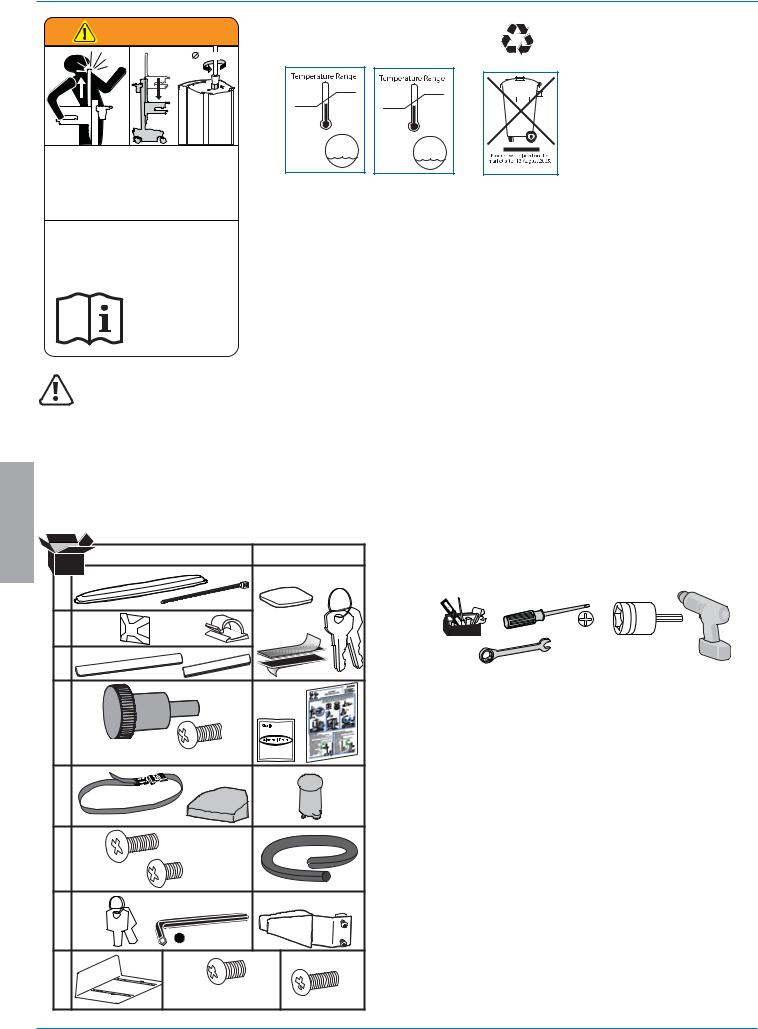
WARNING |
AVERTISSEMENT |
14mm (9/16”) |
IMPACT HAZARD!
MOVING PARTS CAN CRUSH AND CUT.
Failure to heed this warning may result in serious personal injury or property damage!
Minimize Lift Tension BEFORE:
Removing Mounted Equipment, Shipping Cart, Storing Cart.
DANGER D’IMPACT !
LES PARTIES EN MOUVEMENT PEUVENT ÉCRASER ET COUPER.
Il existe un risque de blessure corporelle ou d’endommagement matériel en cas de non respect de cet avertissement.
Minimisez la tension d’élévation AVANT :
de retirer l’équipement fixé, d’expédier le chariot, de stocker le chariot
www.ergotron.com
826-501
LEAD
BATTERY
|
29 °C |
|
|
|
|
|
|
|
|
|
|
|
|
|
|
|
|
|
|
|
50 °C |
|
|
||||||
|
86 °F |
|
|
||||||
10 °C |
122 °F |
|
|
|
|
|
|||
|
|
|
|
|
|||||
|
-20 °C |
|
|
||||||
50 °F |
|
|
|
||||||
|
- 4 °F |
|
|
||||||
|
|
|
|
||||||
Relative |
Relative |
Humidity 5-95% rH |
Humidity 5-95% rH |
Range |
Range |
Operational |
Storage |
This Class A digital apparatus complies with Canadian ICES-003.
Cet appareil numérique de la classe A est conforme à la norme NMB-003 du Canada.
FCC Compliance Statement
The cart has been tested and found to comply with the limits for a Class A digital device, pursuant to part 15 of the FCC Rules. These limits are designed to provide reasonable protection against harmful interference when the equipment is operated in a commercial environment. This equipment generates, uses, and can radiate radio frequency energy and, if not installed and used in accordance with the instruction manual, may cause harmful interference to radio communications. Operation of this equipment in a residential area is likely to cause harmful interference in which case the user will be required to correct the interference at his own expense.
Changes or modifications not expressly approved by Ergotron, Inc. could void the user’s authority to operate the equipment.
Please contact Ergotron for complete EMC compatibility information.
IMPORTANT! This product will need tension adjustments once installation is complete. Make sure all equipment is properly installed on the product before attempting range of motion or tension adjustments. Any time equipment is added or changed on this product resulting in a different mounted weight, you should repeat the adjustment steps to ensure safe and optimum operation. This product should move smoothly and easily through the full range of motion and stay where you set it. If movement is difficult or the product does not stay where you set it, follow the adjustment instructions to loosen or tighten the tension to create a smooth, easy motion. Depending on your product and the adjustment, it may take many turns to notice a difference.
ENGLISH |
Components |
|
|
|
|
|
|
|
|
|
|
|
|
||
|
|
|
A |
|
B |
|
|
|
1 |
1x |
12x |
4x |
2x |
Tools Needed |
|
|
|
|
|
|
|
||
|
|
|
|
|
|
|
|
|
2 |
1x |
1x |
2x |
|
10mm |
14mm (9/16") |
|
|
1x |
1x |
|
|||
|
3 |
2x1x |
|
|
|
||
|
|
4x |
M4 x 10mm |
|
|
|
|
|
|
|
|
|
|
|
|
|
4 |
|
|
|
|
|
|
|
|
8x M4 x 10mm |
|
|
|
|
|
|
5 |
1x |
1x |
4x |
|
|
|
|
|
|
|
|
|||
|
|
|
|
|
|
|
|
|
6 |
1x |
M4 x 8mm |
1x |
|
|
|
|
1x |
M4 x 5mm |
|
|
|||
|
|
|
|
|
|
||
|
7 |
1x |
1x |
|
1x |
|
|
|
|
|
|
|
|
|
|
|
|
|
3mm |
|
|
|
|
|
8 |
1x |
1x |
|
2x |
|
|
|
|
|
M4 x 8mm |
|
|
|
|
|
|
|
|
M4 x 12mm |
|
|
|
|
2/23 |
|
|
|
|
|
888-24-175-G-01 rev. M • 02/16 |
Features & Specifications
Part Number |
Power System |
SV42-6301-1 |
Input: 120VAC/60 Hz, 5.1A; |
|
Output: 120VAC/60 Hz, 400VA, 300W. |
|
• The cart and power system are certified to UL 60601 and CAN/CSA-C22.2 601.1-M90 |
|
|
SV42-6301-2 |
Input: 230V~/50 Hz, 2.7A; |
SV42-6301-3 |
Output: 230V~/50 Hz, 400VA, 300W. |
SV42-6301-B |
• The cart and power system are compliant with EN 60601-1. |
|
|
SV42-6301-C |
|
SV42-6301-7 |
Input: 220V~/60 Hz, 2.7A; |
SV42-6301-8 |
Output: 220V~/60 Hz, 400VA, 300W. |
2 3 1


5 |
|
|
9 |
|
|
4/11 |
17 |
2a |
|
18 |
|
13 |
|
|
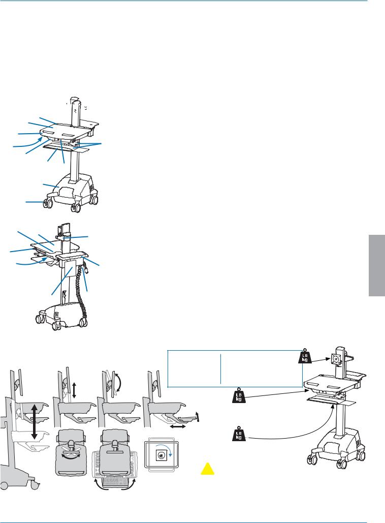
1.Height Adjustable LCD Mount attaches LCDs or tablet PC's with 75x75 or 100x100mm mounting interface
Worksurface 2a. Worksurface Lock and Release User Interface
Secure Storage for Laptop, Thin Client or CPU
8Front Handle
Height Adjustment Brake Handle
USB Hub connects keyboard and mouse USB cables
Keyboard tray slides out, tilts and allows for right or left mousing with attached mouse holder Keyboard Light under Front Handle
Keyboard Light Switch
Cable Management and Storage for excess cables and power supplies Storage Basket and Rear Handle
Front Locking Casters Quick Reference Card Power Cord Hooks Scanner Holder
Antimicrobial coating on worksurface and wrist rest
10 |
17 |
16 |
Power System |
The StyleView AC Power System allows your power supply to travel with the cart. The Power System is |
|||
|
|
integrated in the base of the cart and comes standard with 2 batteries, power module, User Interface (UI), outlet |
|
6 |
|
|
box and power cord. |
|
|
• User Interface (UI): Allows power system output to be turned on or turned off, monitors battery charge |
|
7 |
|
12 |
remaining, and provides low battery charge audible alarm. |
|
• Two 33 Ah Sealed Lead Acid, Absorbed Glass Mat, 12VDC batteries. |
||
|
|
|
• The minimum operational temperature is 10°C (50°F) and the maximum operational temperature is 29°C (86°F). The |
|
|
|
recommended humidity range for operation is 5-95% rH. |
|
|
|
• The recommended cart storage temperature is 15°C (59°F). At this temperature, the battery’s age-related |
|
14 |
15 |
capacity loss is minimized. The minimum storage temperature is -20°C (-4°F) and the maximum storage |
|
temperature is 50°C (122°F). The recommended humidity range for storage is 5-95% rH. |
ENGLISH
|
Weight Capacity With Independent LCD Lift: |
Without Independent LCD Lift: |
|
|
6-14 lbs (2.7-6.4 kg) |
20 lbs (9 kg)* |
|
|
20˚ |
|
* See "How To Eliminate Independent LCD |
|
|
Lift" section |
|
20" |
5" |
|
|
(127 mm) |
|
|
|
(508 mm) |
5˚ |
|
|
|
12˚ |
0 lbs (0 kg) Open Worksurface |
|
|
|
<5 lbs (2.3 kg) Closed Worksurface |
|
|
|
<13 lbs (5.9 kg) CPU Compartment |
|
|
|
|
<3 lbs (1.4 kg) |
|
|
|
*Combined LCD and CPU Compartment weight: |
|
24˚ |
|
<27 lbs (12.2 kg). |
|
|
|
|
90˚ |
90˚ |
 CAUTION:
If the combined LCD and CPU weight is greater than 27 lbs (12.2 kg) then the CPU must be mounted to the rear of the cart using the Universal CPU Holder accessory (ordered separately).
888-24-175-G-01 rev. M • 02/16 |
3/23 |
1
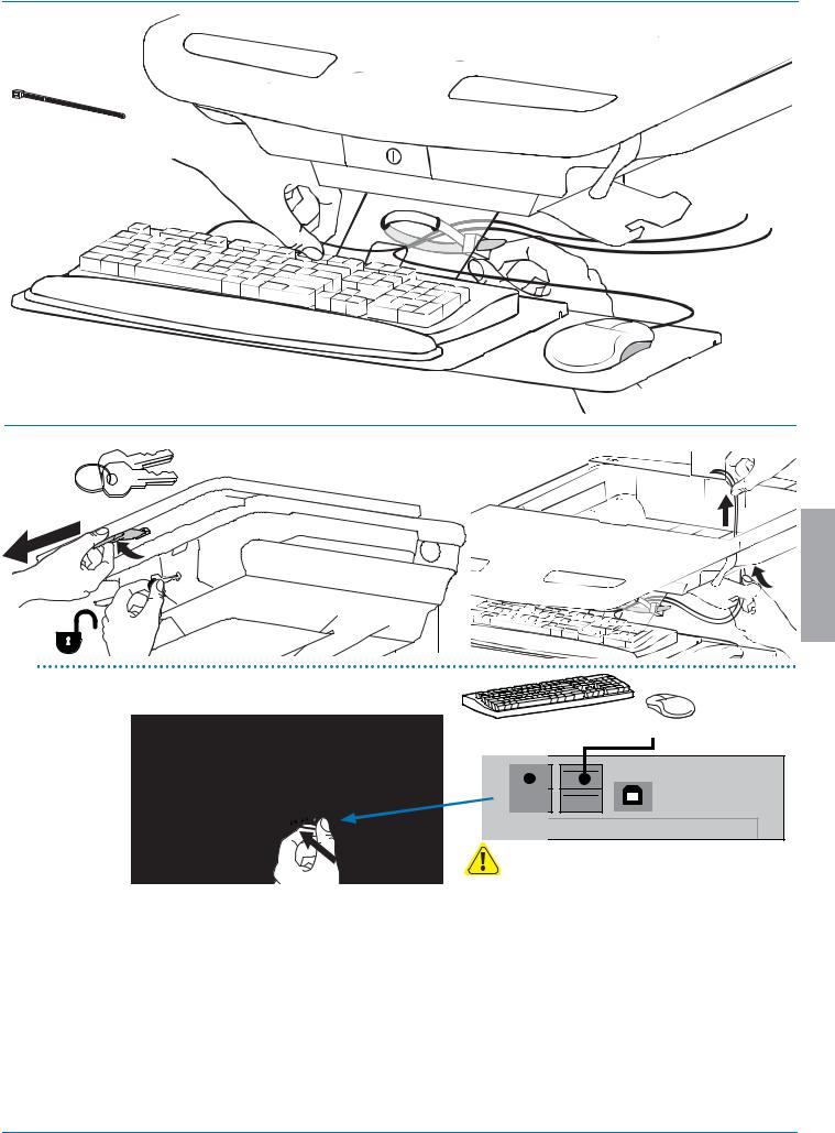
Release Brake to move riser.
CAUTION! Completely release brake engagement before raising or lowering the cart. Raising or lowering the cart with the brake partially engaged may cause product damage.
ENGLISH
2 a 
1x 
1x
b |
1x |
1x 


4/23 |
888-24-175-G-01 rev. M • 02/16 |
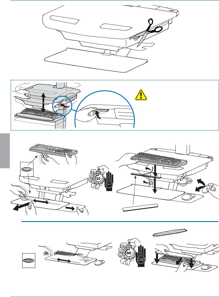
Set-up
c
1x
3 a |
b |
ENGLISH
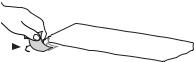
cConnect Keyboard and Mouse to USB Hub
USB (Type A) |
USB (Type A) |
NOTE: Bar Code Scanner should be connected directly to computer USB port.
DO NOT connect Bar Code Scanner to the USB Hub.
888-24-175-G-01 rev. M • 02/16 |
5/23 |
Set-up
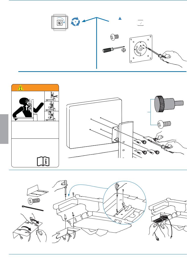
4a

 0˚
0˚ 
1x |
0˚ |
M4 x 5mm |
|
b 75x75mm / 100x100mm |
|
|
WARNING |
|
|
AVERTISSEMENT |
|
|
1. |
|
|
2. |
|
|
3. |
|
ENGLISH |
IMPACT HAZARD! |
|
MOVING PARTS CAN CRUSH AND CUT. |
||
Failure to heed this warning may result in serious personal |
||
injury or property damage! |
||
Raise monitor to top of vertical adjustment BEFORE removing. |
||
DO NOT remove Stop Screw without monitor attached. Doing so will |
||
cause monitor pivot to shoot up rapidly and may cause personal injury. |
||
|
||
|
DANGER D’IMPACT ! |
LES PARTIES EN MOUVEMENT PEUVENT ÉCRASER ET COUPER.
Il existe un risque de blessure corporelle ou d’endommagement
matériel en cas de non respect de cet avertissement.
Élevez l’écran au plus haut de l’ajustement vertical AVANT de le retirer. NE retirez PAS la vis d’arrêt avant que l’écran soit fixé.
Dans un tel cas, le pivot d'écran se relèverait rapidement et cela pourrait engendrer des blessures.
www.ergotron.com
4x
M4 x 10mm
826-502
To increase space and improve airflow, power brick may be stored under the storage area.
1x |
b |
c |
2x |
||
2x |
M4 x 12mm |
|
|
|
a
6/23 |
888-24-175-G-01 rev. M • 02/16 |

Set-up
5 a |
b |
c |
|
d |
|
6Plug in power cables.
If you do not have power outlets located here, then follow steps 'a' - 'd' to route power cables.
WARNING! Connecting electrical equipment to the outlet effectively leads to creating a medical system and the result can be a reduced level of safety.
 7
7
a Route power cable down along tower.
1x 
ENGLISH
6' (1.8 m)
Power cables need to be 6' (1.8 m) long.
WARNING
DO NOT OPERATE
WITHOUT
GUARD
IN PLACE 822-447-00
WARNING! DO NOT OPERATE WITHOUT GUARD IN PLACE. Only remove guard when routing a cable with a large connector through the bottom of the compartment. Replace guard imediately after routing cable. Failure to replace guard my result in equipment damage and or personal injury.
b - d
888-24-175-G-01 rev. M • 02/16 |
7/23 |
 Loading...