

Page 1
Page 2
About the Manuals and Notations Used
Types of Manual
The documentation for your EPSON projector is divided into the following two manuals. Refer to the
manuals in the order given below.
Safety Instructions/World-Wide Warranty Terms
This manual contains information on using the projector safely, and also includes a guide for warranty
service, and a troubleshooting check sheet.
Be sure to read this manual thoroughly before using the projector.
User’s Guide (this manual)
This User's Guide contains information on installing the projector, basic operations, using the
configuration menus, troubleshooting and maintenance.
Notations used in this User’s Guide
General information
Indicates procedures where personal injury or damage to the projector may occur if
the procedures are not followed correctly.
Indicates additional information and points which may be useful to know regarding a
TIP
, etc. Indicates buttons on the remote control or projector's control panel.
" (Menu Name) "
[ (Name) ]
topic.
Indicates a page where useful information regarding a topic can be found.
Indicates that an explanation of the underlined word or words in front of this symbol
appears in the glossary of terms.
Refer to the "Glossary" in the "Appendix". p.54
Indicates configuration menu items.
Example: "Image"-"Color Mode"
Indicates the port name of the projector.
Example: [Video]
Meaning of "unit" and "projector"
When "unit" or "projector" appears in the text of this User’s Guide, they may refer to items which are
accessories or optional equipment in addition to the main projector unit itself.
Page 3
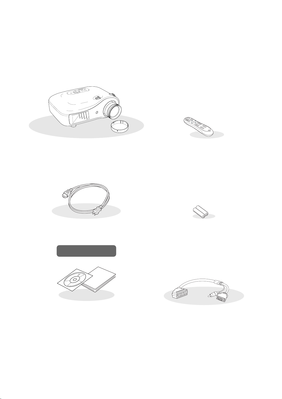
Checking the Components
When you unpack the projector, make sure that you have all these components.
If any of the components are missing or incorrect, please contact the place of purchase.
❏ Projector (with lens cover) ❏ Remote control
❏ Power cable (3.0m)
Connect to the projector and to a wall outlet.
Documentation
❏ Document CD-ROM
(Safety Instructions/World-Wide
Warranty Terms, User’s Guide)
❏ Quick Start Guide
* Some regions may have paper manuals instead of a
CD-ROM, or may not have the Quick Start Guide.
❏ AA alkali batteries (2 pcs.)
Insert into the remote control.
❏ D SCART adapter
Use a commercially-available SCART cable to
make the connections when projecting RGB-video
and component video images.
* Some regions may not have the D SCART adapter
included as an accessory.
1
Page 4

Table of Contents
■ Features of the Projector............................. 4
■ Part Names and Functions.......................... 6
Front / Top.................................................... 6
Control panel ................................................6
Installing the Projector
■ Setting up....................................................10
Adjusting the projection size....................... 10
■ Connecting Image Sources....................... 12
Basic Operations
■ Projecting Images ...................................... 14
Turning the power on
and projecting images ..............................14
Remote control .............................................7
Rear.............................................................. 8
Base .............................................................8
■ Appearance...................................................9
■ Preparing the Remote Control ..................13
Inserting batteries into the remote control .. 13
■ Adjusting the Projection Screen............... 16
Focus adjustment ....................................... 16
Fine adjustments to image size
(Zoom adjustment) ...................................16
Projection image position adjustment
(Lens shift)................................................16
Image Quality Adjustments
■ Basic Image Quality Adjustments ............ 18
Selecting the colour mode.......................... 18
Selecting the aspect ................................... 18
■ Advanced Colour Adjustments................. 20
Skin tone adjustment.................................. 20
Absolute colour temperature adjustment.... 20
Gamma adjustment .................................... 20
RGB adjustment (Offset, Gain) ..................22
Hue and saturation adjustment ..................22
Configuration Menu
■ Configuration Menu Functions ................. 26
Using the configuration menus................... 26
List of configuration menus ........................28
"Image" menu............................................. 30
"Signal" menu............................................. 31
■ Examining Image Quality Further............. 23
Sharpness (Advanced) adjustment ............ 23
Auto Iris (automatic aperture) setting .........23
■ Viewing Images at a Preset Image Quality
(Memory Function)...................................... 24
Saving, Loading and Erasing Memory .......24
"Settings" menu.......................................... 33
"Memory" menu.......................................... 35
"Reset" menu..............................................35
2
Page 5

Troubleshooting
Table of Contents
■ Problem Solving ........................................ 36
Reading the indicators ............................... 36
• When the (warning) indicator is lit or
flashing...............................................................36
• When the (operation) indicator is lit or
flashing...............................................................37
Appendix
■ Maintenance............................................... 44
Cleaning..................................................... 44
• Cleaning the air filter............................................44
• Cleaning the projector case ..................................44
• Cleaning the lens ..................................................44
Consumable replacement periods ............. 45
• Air filter replacement period ................................45
• Lamp replacement period .....................................45
Replacing consumables............................. 46
• Replacing the air filter ..........................................46
• Replacing the lamp ...............................................46
• Resetting the lamp operating time ........................46
When the indicators provide no help.......... 37
• Problems relating to images................................. 38
• Problems when projection starts .......................... 43
• Problems with the remote control........................ 43
■ Optional Accessories / Consumables ..... 48
■ List of Supported Monitor Displays......... 49
• Component Video ................................................ 49
• Composite Video/S-Video ................................... 49
• Computer image (analog RGB) ........................... 50
• Input signal from the [HDMI] input port............. 50
■ Specifications ............................................ 51
■ Glossary ..................................................... 54
■ Index ........................................................... 56
projector
Installing the
Basic
operation
Adjustments
Configuration
Appendix Troubleshooting Image Quality
Menu
3
Page 6
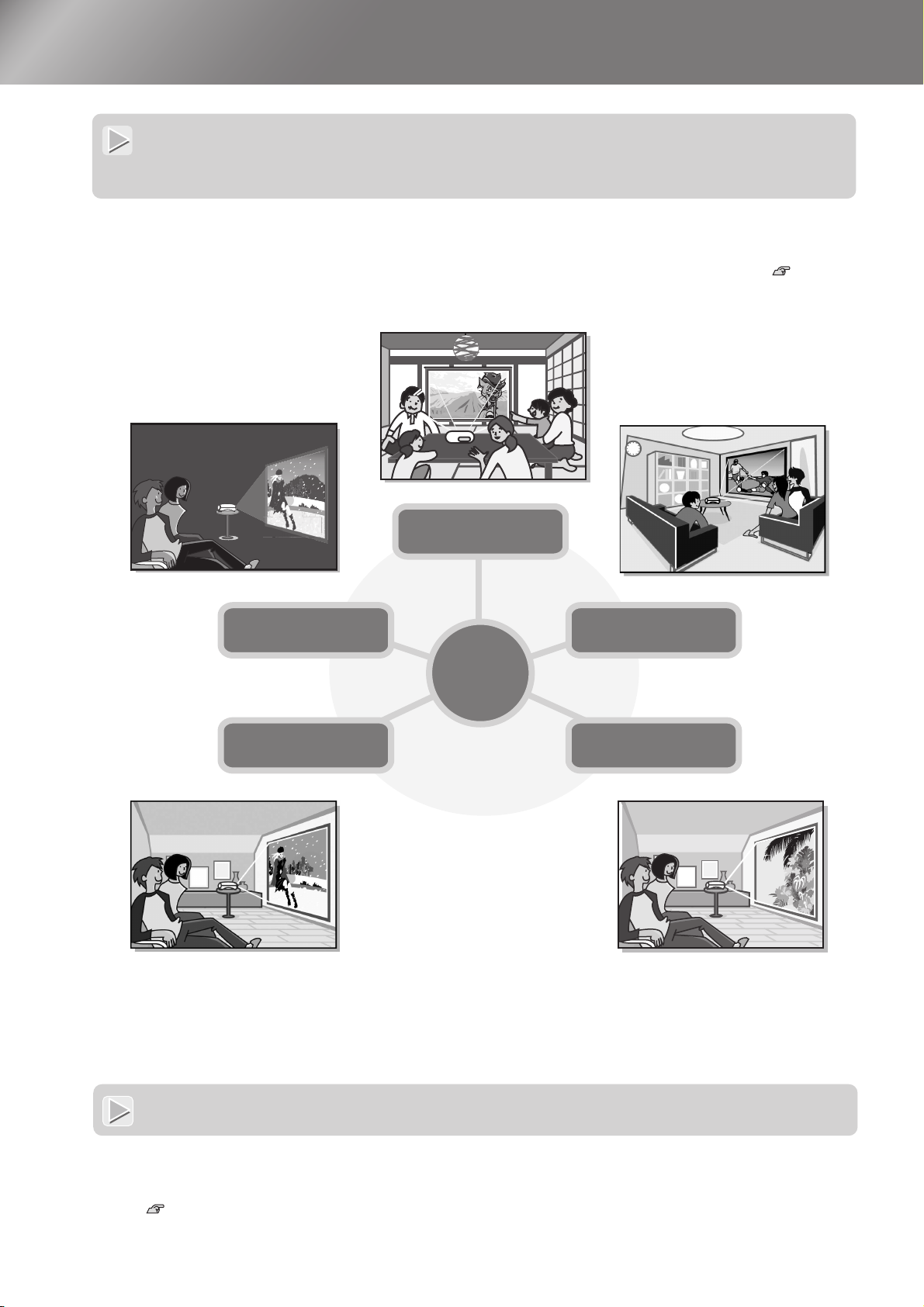
Features of the Projector
Image appearance can be selected to match the
projection environment (Color Mode)
The optimum images for the location can be projected simply by selecting the desired colour mode from the
following six preset modes.
If "Natural", "Theatre", "Theatre Black 1" or "Theatre Black 2" is selected, the Epson Cinema Filter effect is
applied automatically to increase the contrast and to make skin tones appear with more natural tints. p.18
Theatre Black1
Theatre Black2
Theatre
Dynamic
Living Room
Color
Mode
Natural
4
Sophisticated colour adjustment
In addition to the "Color Mode", the absolute colour temperature and skin tones can be adjusted by simple
procedures to render the picture even more to your own liking. Further, you can adjust gamma, the offset and
gain for RGB colours, and the hue and saturation of RGBCMY colours, to create colours that match the image.
p.20
Page 7
Equipped with a wide-
p
angle lens shift function
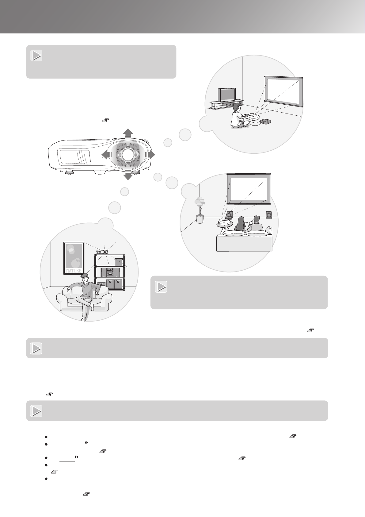
The lens shift function allows the position of the
projected images to be adjusted vertically and
horizontally without distorting the images.
This can allow the projector to be set up with greater
freedom, even if it is suspended from a ceiling or at
an angle to the screen. p.16
Features of the Projector
Equipped with 2.1x short
throw zoom lens
For zoom adjustment, 2.1x short throw zoom lens is provided.
Images can be projected onto an 100" screen (16:9 screen
only) even at a distance of approximately 3 m (10 ft.). p.10
Advanced image quality adjustment functions
Advanced image quality adjustment functions such as "Auto Iris" and "Sharpness (Advanced)" can be used to
enjoy even sharper images. With the Auto Iris function turned on, the amount of light can be automatically
adjusted to match the images being projected, to create images with depth and perspective. The Sharpness function
is used to adjust not only the entire image, but also to emphasize specific regions, such as hair and clothing.
p.23
A variety of image setting functions
Some of the other many functions that are available are as follows.
EPSON Super White is used to prevent overexposure that can result in images that are too bright. p.32
A progressive conversion that lets you obtain ideal results both for images with large amounts of movement
and for still images. p.32
An aspect function that allows images to be viewed in wide-screen format. p.18
Memory functions that allow adjustment results to be stored and later retrieved easily using the remote control.
p.24
Lock settings that can be used to lock the projector's control panel after adjustments have been made so that
they cannot be changed by mistake, or to prevent children from accidentally turning on the power and looking
into the lens.
.33
5
Page 8
Part Names and Functions
Hori
l
16
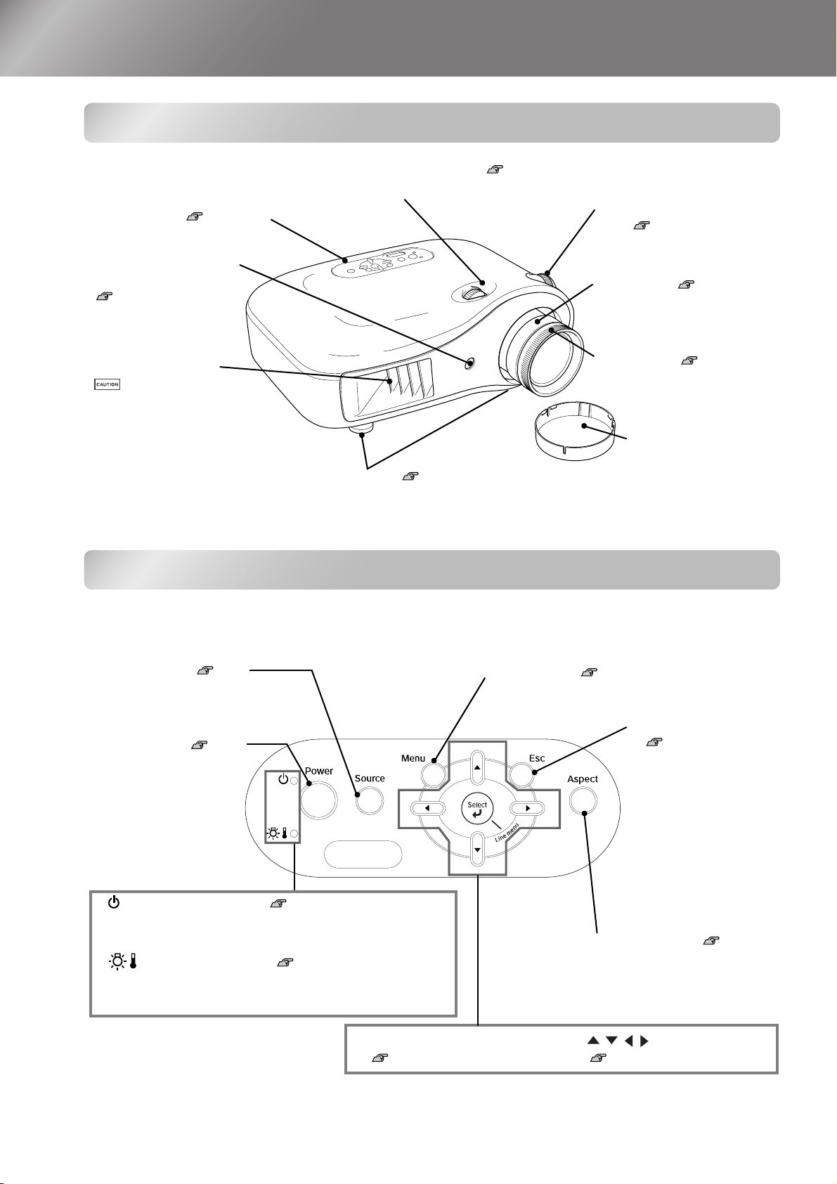
Front / Top
•
zontal lens adjustment dia
Moves the lens horizontally.
• Control panel See below
• Remote control light-
receiving area
p.13
Receives signals from the
remote control.
p.
• Vertical lens adjustment
dial p.16
Moves the lens vertically.
• Zoom ring p.16
Adjusts the image size.
• Air exhaust vent
Do not touch the exhaust vent
immediately after projecting, or
while projecting, since it
becomes hot.
• Front adjustable feet p.17
Extend to adjust the projection angle so that the
projector is horizontal when placed on a desk top.
• Focus ring p.16
Adjusts the image focus.
• Lens cover
Attach when not using
the projector to prevent
the lens from becoming
dirty or damaged.
Control panel
Buttons with no explanation function in the same way as the corresponding buttons on the remote
control. Refer to "Remote control" for further details on these buttons.
• Source button p.15
Selects the image source.
• Power button p.14
Turns the projector power
on or off.
• Menu button p.26
• Esc button
p.18, 20
, 24,
26
6
• (Operation) indicator p.37
Flashes or lights in different colours to indicate the operating
status of the projector.
• (Warning) indicator p.36
Flashes or lights in different colours to indicate problems
with the projector.
• Select/Line menu buttons
p.18, 24, 26
• Aspect button p.18
• buttons
p.18, 20, 22, 26
Page 9
Remote control
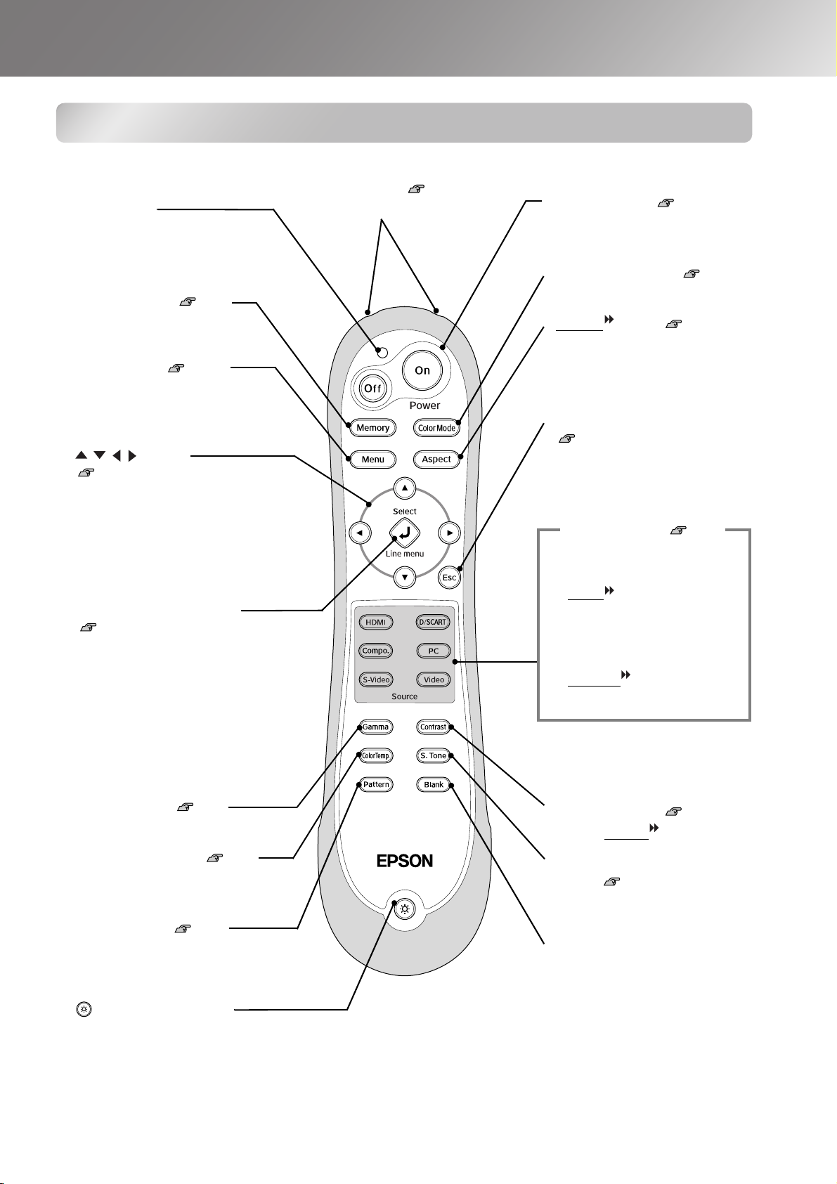
Indicator
Illuminates when remote control
signals are being output.
• Memory button p.24
Retrieves stored memories.
• Menu button
Displays the full-screen
configuration menus.
• button
p.18, 20, 22, 26
Press to select menu items and
adjustment values.
p.26
• Remote control light-
emitting area p.13
Outputs remote control signals.
Part Names and Functions
• On/Off buttons p.14
Turns the projector power on/off.
• Color Mode button p.18
Selects the colour mode.
• Aspect
Selects the aspect.
button p.18
• Esc button
p.18
, 20, 24,
Pressing [Esc] while viewing a
menu displays the previous menu.
Source buttons p.15
Switches to an image input from
equipment connected to the port.
26
• Select/Line menu button
p.18, 24
Displays the line menu.
When viewing a menu, press this
button to select the menu item and
proceed to the next display.
,
26
• Gamma button p.20
Adjusts the gamma values.
• Color Temp. button p.20
Adjusts the absolute colour
temperature.
• Pattern button p.17
The test pattern image appears and
disappears each time this button is
pressed.
• (Illumination) button
All buttons on the remote control illuminate when this button is pressed.
The button illumination switches off automatically after about 10 seconds
have passed.
• HDMI button
• D/SCART button
• Compo. button
• PC button
• S-Video button
• Video button
• Contrast button p.30
Adjusts contrast
.
• S.Tone (Skin Tone)
button p.20
Adjusts the skin tones of people
who appear in the images.
• Blank button
The projected images switch off
and on each time this button is
pressed.
7
Page 10
Part Names and Functions
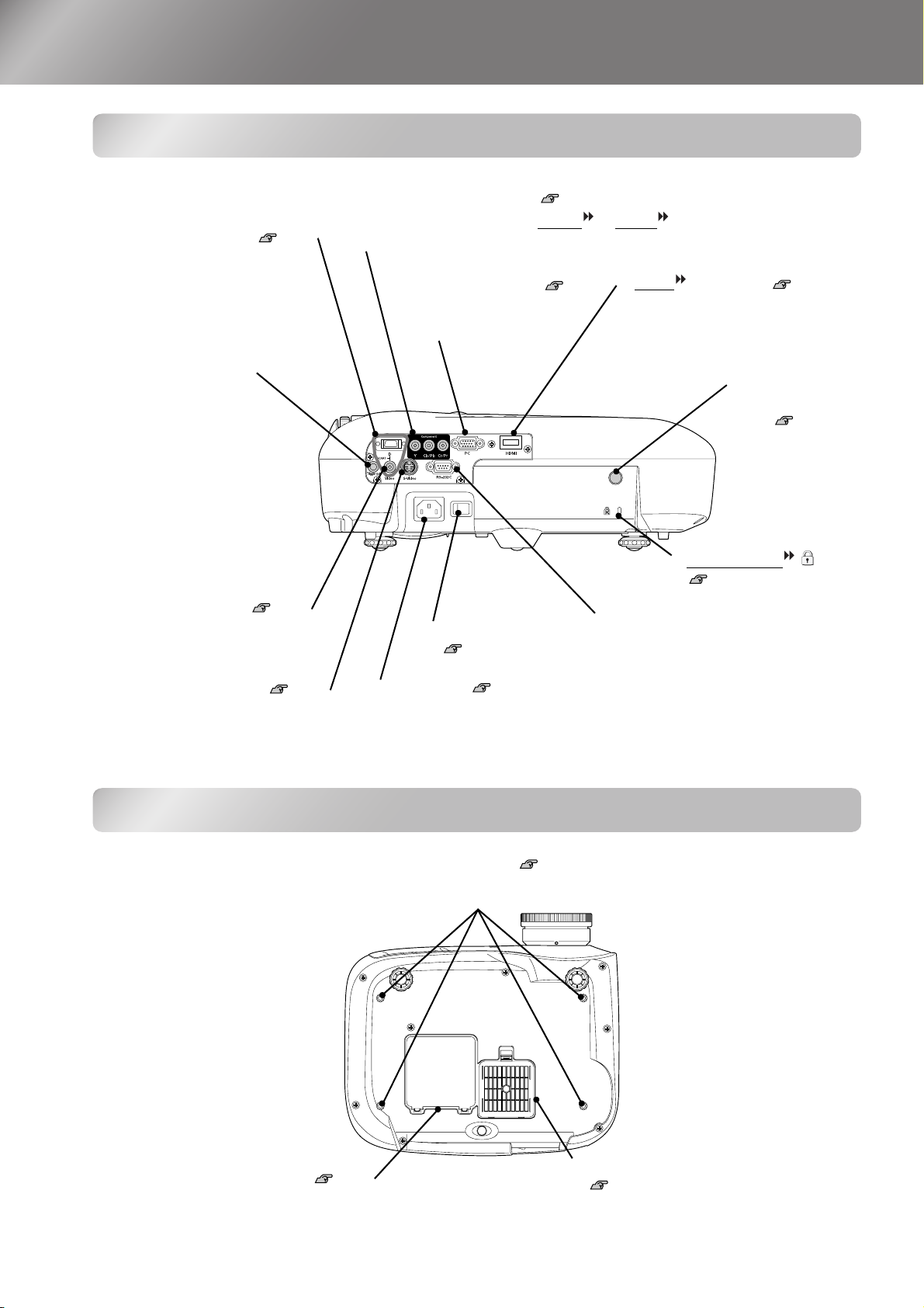
Rear
• [SCART] input port p.12
Connects to the component
(YCbCr or YPbPr) out port or D
out port of the video equipment.
• [Component] input port p.12
Connects to the component (YCbCr
video equipment.
• [PC] input port p.12
Connects to the RGB out
port of the computer.
or YPbPr ) out port of the
• [HDMI ] input port p.12
Connects to video equipment or a
computer that is HDMIcompatible.
• [Trigger out] port
When the projector power
is turned on, a 12 V DC
signal is output from this port.
When the projector's power is
turned off or a problem with
operation occurs, the output
becomes 0 V to send the
projector's power ON/OFF
status to an external device.
• [Video] input port p.12
Connects to general video out
ports of the video equipment.
• [S-Video] input port p.12
Connects to the S-Video out ports of
the video equipment.
Base
• Main power switch
p.14
• Power inlet p.14
Connects the power cable.
• Remote control
light-receiving
area p.13
Receives signals
from the remote
control.
• Security lock
p.55
• [RS-232C] port
Connects the projector to a computer
using an RS-232C cable. This port is
for control use and should not be used
by the customer.
8
• Suspension bracket fixing points (4 points) p.48
Install the optional ceiling mount here when suspending the projector from a ceiling.
• Lamp cover p.46
Open this cover when replacing the lamp
inside.
• Air filter (air intake vent)
p.44, 46
Prevents dust and other foreign particles
from being drawn into the projector.
It should be cleaned periodically.
Page 11
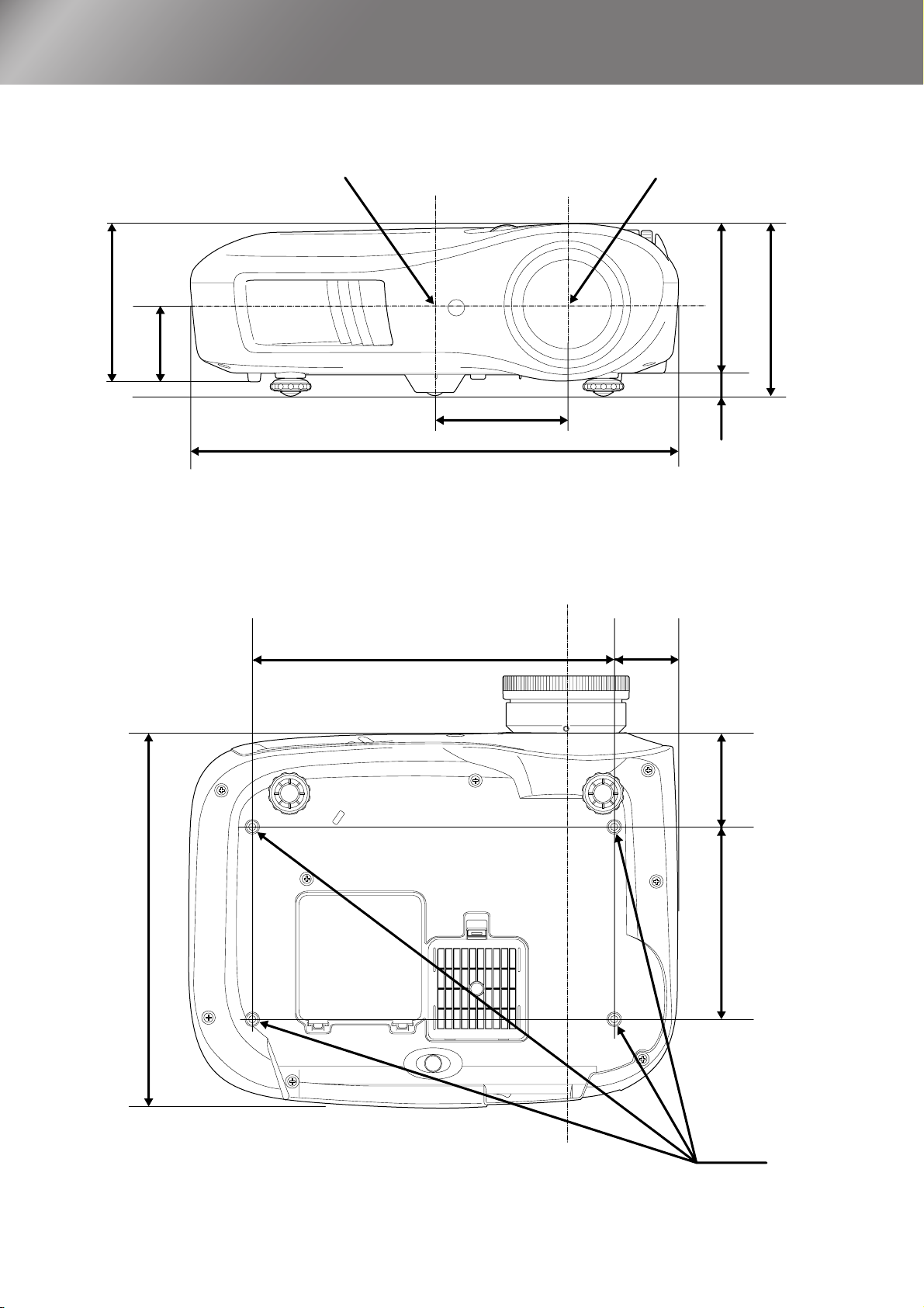
Appearance
131.5
66
Centre of projector
*1
*2
110
406
*1 Distance from centre of lens to suspension bracket fixing point
(Lens shift amount: Max. 8.8 mm vertically)
*2 Distance from centre of lens to centre of projector
(Lens shift amount: Max. 7.7 mm horizontally)
Centre of lens
Centre of lens
124
19
143
310
300
52.8
77.3
160
4-M4×8
Units:mm
9
Page 12
Setting up
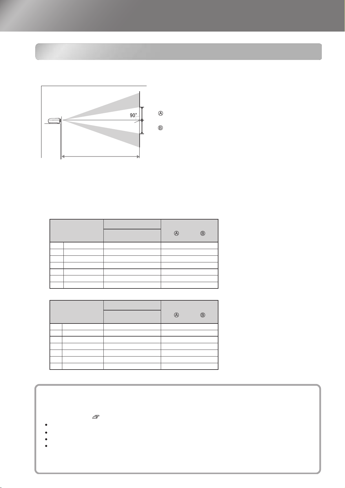
Adjusting the projection size
The size of the projected image is basically determined by the distance from the projector's lens
to the screen.
Lens shift
To p
Offset
Centre of lens
Adjusting the projection size
Projection distance
Offset
Lens shift
Bottom
The height from the centre of the lens to the bottom of the
screen will vary depending on the lens shift setting.
While referring to the table below, position the projector so that the images are projected onto the
screen at the optimum size.
The values should be used as a guide for setting up the projector.
to
to
Units: cm (in.)Units: cm (ft.)
Offset
Units: cm (in.)Units: cm (ft.)
Offset
Units: cm (in.)
16:9 screen size
30"
66×37 (26×15)
40"
89×50 (35×20)
130×75 (51×28)
60"
80"
180×100 (71×39)
100"
220×120 (87×47)
270×150 (106×59)
120"
330×190 (130×75)
150"
Units: cm (in.)
4:3 screen size
30"
61×46 (24×18)
40"
81×61 (32×24)
60"
120×90 (47×35)
80"
160×120 (63×47)
100"
200×150 (79×59)
240×180 (94×71)
120"
300×230 (118×91)
150"
Projection distance
Shortest
(Wide)
87 to 188 (2.8 to 6.2)
117 to 252 (3.8 to 8.3)
177 to 380 (5.8 to 12.5)
238 to 508 (7.8 to 16.7)
298 to 636 (9.8 to 20.9)
359 to 764 (11.8 to 25.1)
450 to 956 (14.7 to 31.4)
Projection distance
Shortest
(Wide)
106 to 230 (3.5 to 7.6)
143 to 309 (4.7 to 10.1)
217 to 465 (7.1 to 15.3)
291 to 622 (9.6 to 20.4)
365 to 778 (12.0 to 25.5)
439 to 935 (14.4 to 30.7)
550 to 1170 (18.0 to 38.4)
to
to
Longest
(Tele)
Longest
(Tele)
Offset
17 to -17 (6.8 to -6.8)
23 to -23 (9.1 to -9.1 )
35 to -35 (13.6 to -13.6)
46 to -46 (18.2 to -18.2)
58 to -58 (22.7 to -22.7)
69 to -69 (27.2 to -27.2)
86 to -86 (34.0 to -34.0)
Offset
21 to -21 (8.3 to -8.3)
28 to -28 (11.1 to -11.1 )
42 to -42 (16.7 to -16.7)
56 to -56 (22.2 to -22.2)
71 to -71 (27.8 to -27.8)
85 to -85 (33.3 to -33.3)
106 to -106 (41.7 to -41.7)
10
Lens shift adjustment
The lens shift dials can be used to position the image and is especially useful when using the projector in the
following locations. p.16
Hanging from the ceiling
A screen in a high location
Projector situated to the side so that the screen can be viewed sitting right in front of it
Projector situated on a shelf, etc.
When positioning an image using the lens shift dial, hardly any deterioration of the image occurs because the lens
shift correction is adjusted optically. However, for optimal image quality the lens shift function should not be used.
Page 13
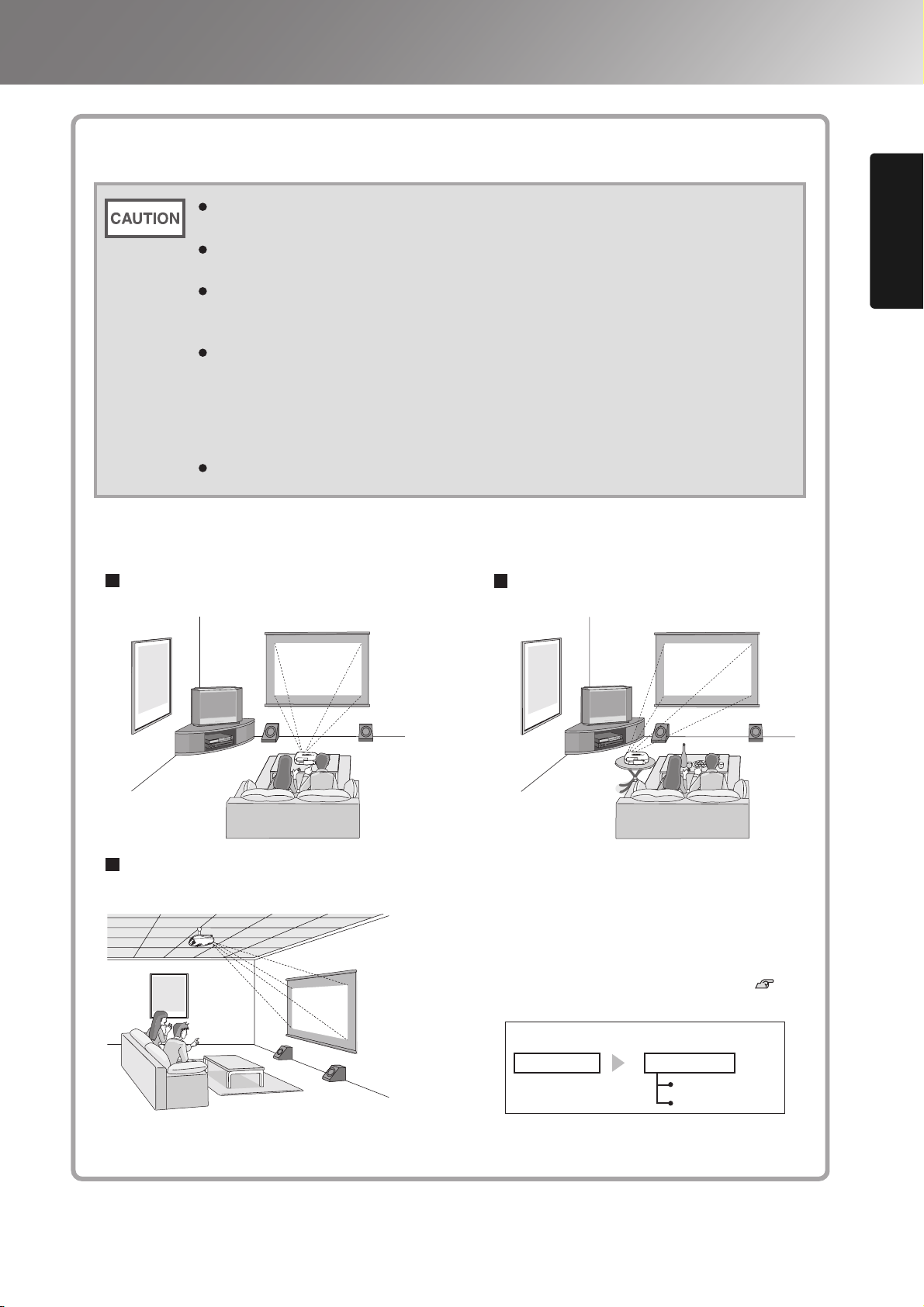
Projection methods
Avoid setting the projector up in a place which is very dusty or humid, or where there
will be cigarette or other smoke, especially oily smoke.
Clean the air filter at least once every 3 months.
Clean the air filter more frequently if using the projector in a dusty environment.
A special method of installation is required when suspending the projector from the
ceiling (ceiling mount). If it is not installed correctly, it could fall causing an accident
and injury.
If you use adhesives on the ceiling mount to prevent the screws from loosening, or if
you use things such as lubricants or oils on the projector, the projector case may
crack causing it to fall from its ceiling mount. This could cause serious injury to
anyone under the ceiling mount and could damage the projector.
When installing or adjusting the ceiling mount, do not use adhesives to prevent the
screws from loosening and do not use oils or lubricants and so on.
Do not use the projector on its side. This may cause malfunctions to occur.
Setting up
When projecting from directly in front
When projecting from a celling
When projecting from the side of
the screen
* Even if projection will be from the screen
side, set up the screen and projector so that
they are parallel.
* When suspending the projector from a ceiling,
change the configuration menu settings. p.34
Installing the Projector
Configuration menu
Settings
Projection
Front
Front/Ceiling
11
Page 14
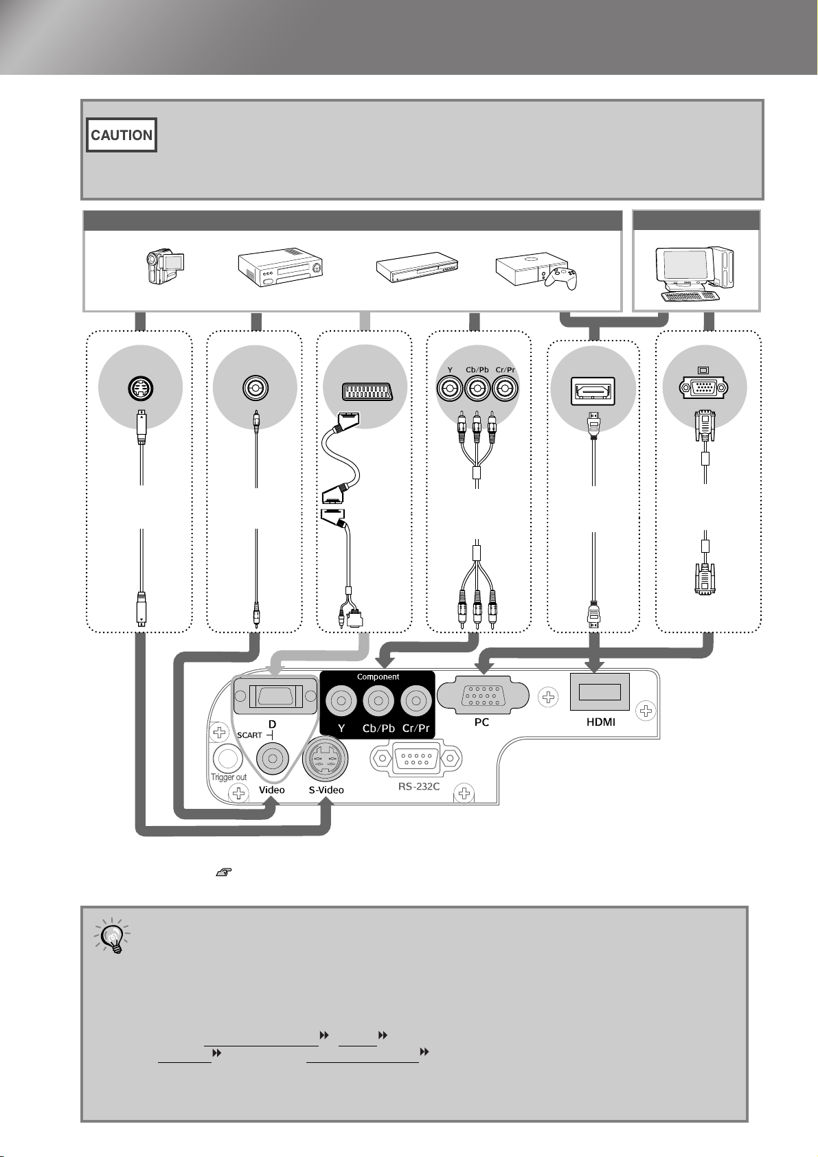
Connecting Image Sources
• Turn the power off for both the projector and the signal source before connecting them.
If the power for either device is on at the time of connection, damage may result.
• Check the shapes of the cable connectors and the device ports before making the
connections. If you try to force a connector to fit a device port with a different shape or
number of terminals, a malfunction or damage to the connector or port may result.
Video equipment (VHS VCR, DVD player, game console, etc.)
*Port names may vary depending on the equipment being connected.
S-Video
S-Video cable
(commercially-
available)
Video
RCA video cable
(commercially-
available)
1
*
SCART
SCART cable
(commercially-
available)
+
D SCART
adapter*
(accessory)
Component output
Component
video cable
(commercially-
available)
2
HDMI
HDMI cable
(commercially-
available)
Computer
Mini D-Sub
15-pin
Computer cable
(commercially-
available)
Mini D-Sub
15-pin
12
*1 If a DVD has been connected using a D SCART adapter, change the "D/SCART" setting in the "Input Signal" to
"SCART". p.34
*2 Some regions may not have the D SCART adapter included as an accessory.
• Some signal sources may have specially-shaped ports. In such cases, use the
accessory or optional cables that are supplied with the signal source to make the
TIP
connections.
• The cable that should be used to connect video equipment to the projector will depend
on the type of video signal that the equipment outputs. Some kinds of video equipment
output several different types of video signal. The image quality ranking of the video
signal types is generally held to be as follows, in descending order of quality:
Digital component video
S-Video
[S-Video] > Composite video [Video]
[HDMI ] > Analog component video [D] [Component] >
You should refer to the documentation provided with the video equipment being used to
check what types of video signal formats the equipment can output. The composite
video format is sometimes simply called "video output".
Page 15
Preparing the Remote Control
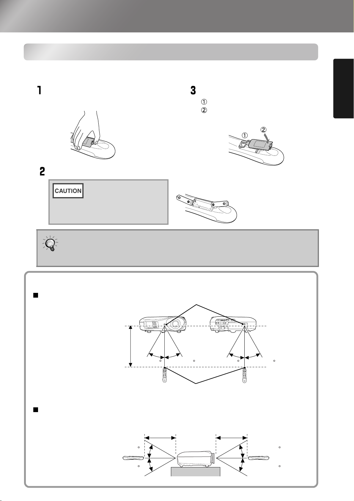
Inserting batteries into the remote control
The remote control is not supplied with batteries already inserted. Insert the accessory batteries
before using the remote control.
Remove the battery cover.
While pressing the knob, lift up.
Insert the batteries.
Check the (+) and (-)
indications inside the
battery compartment and
insert the batteries so that
they face correctly.
If delays in the responsiveness of the remote control occur or if it does not operate
after it has been used for some time, it probably means that the batteries are
TIP
becoming flat. If this happens, replace the batteries with two new batteries. Use two
new AA batteries as replacement batteries.
Install the battery cover.
Insert the tab.
Press down until the battery
cover clicks into place.
Installing the Projector
Using the remote control
Operating range (horizontal)
Operating distance
Approx.10m
Operating range (vertical)
Approx.30
Remote control light-receiving area
Approx.30
Operating distance
Approx.10m
Approx.30 Approx.30 Approx.30
light-emitting area
Remote control
Operating distance
Approx.10m
Approx.30
Approx.30
Approx.30
13
Page 16

Projecting Images
Turning the power on and projecting images
Remove the lens cover.
Turn the power on.
Connect the power
cable.
Turn on the main power
switch.
ON
Control Panel
Remote Control
Turn the power on for the
connected equipment.
14
If there is a problem with projection even though the projector is set up and connected correctly,
refer to p.15, 36.
If you set the "Direct Power On" to "On", the power of the unit will turn ON when
the main power switch is turned ON, without having to press the power button of
TIP
the remote control or the projector's control panel.
The projector is equipped with a "Child Lock" function that prevents young
children from accidentally turning the power on and looking into the lens, and
also an "Operation Lock" function that prevents mis-operations. p.33
When using above an altitude of about 1500 m, make sure you set the "High
Altitude Mode" to "On". p.33
This projector is equipped with an automatic
adjustment function that automatically optimizes it
when a computer input signal is switched.
If a laptop computer or a computer with a LCD
screen has been connected to the projector, you
may need to use keyboard or function settings to
change the output destination. While holding down
the key, press (the key with a symbol such
as / on it). After the selection is made,
projection will soon start.
Example of output selection
NEC
Panasonic
SOTEC
HP
Toshiba
IBM
SONY
DELL
Fujitsu
Set mirror setting or
Macintosh
display detection.
Depending on OS, you can
change the output
selection by pressing .
Computer documentation
Page 17
Projecting Images
When the expected images are not projected
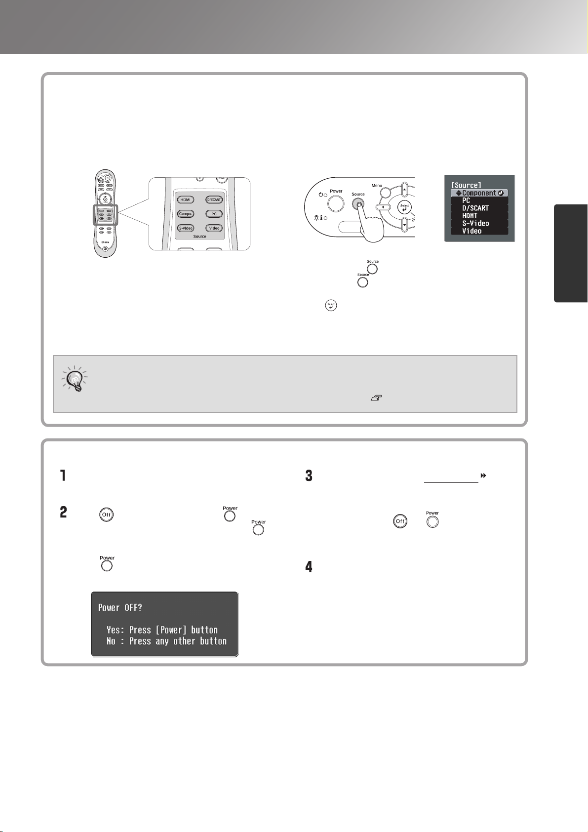
If more than one signal source has been connected, or if no images are projected, use the remote control or the
projector's control panel buttons to select the signal source. For video devices, press the [Play] button on the video
equipment first, then select the signal source.
Using the remote control
Using the control panel
When the expected images are not
projected
Turning the power off
Press the button that has the name of the port on it that
the desired signal source is connected to.
When the colour of the image projected from the [D] or [Component] input port
is unnatural, select an appropriate signal according to the signal from the device
TIP
connected at "Input Signal" in the Configuration menu. p.34
Turning the power off
Turn the power off for the signal sources
that are connected to the projector.
Press on the remote control or on
the projector's control panel. If you press
on the projector's control panel, the
following message will be displayed.
Press again to continue.
When you press , the menu is displayed.
Each press of moves the pointer. Move the pointer
to the target input source to select it.
Press to accept. The input source is automatically
changed if no operations are performed for about 5
seconds with the pointer at the target input source.
Basic Operations
When the projector has cooled down (takes
about 30 seconds), turn off the main power
switch.
Simply pressing or does not stop
electricity consumption.
Attach the lens cover.
15
Page 18
Adjusting the Projection Screen
1/2H
1/2V
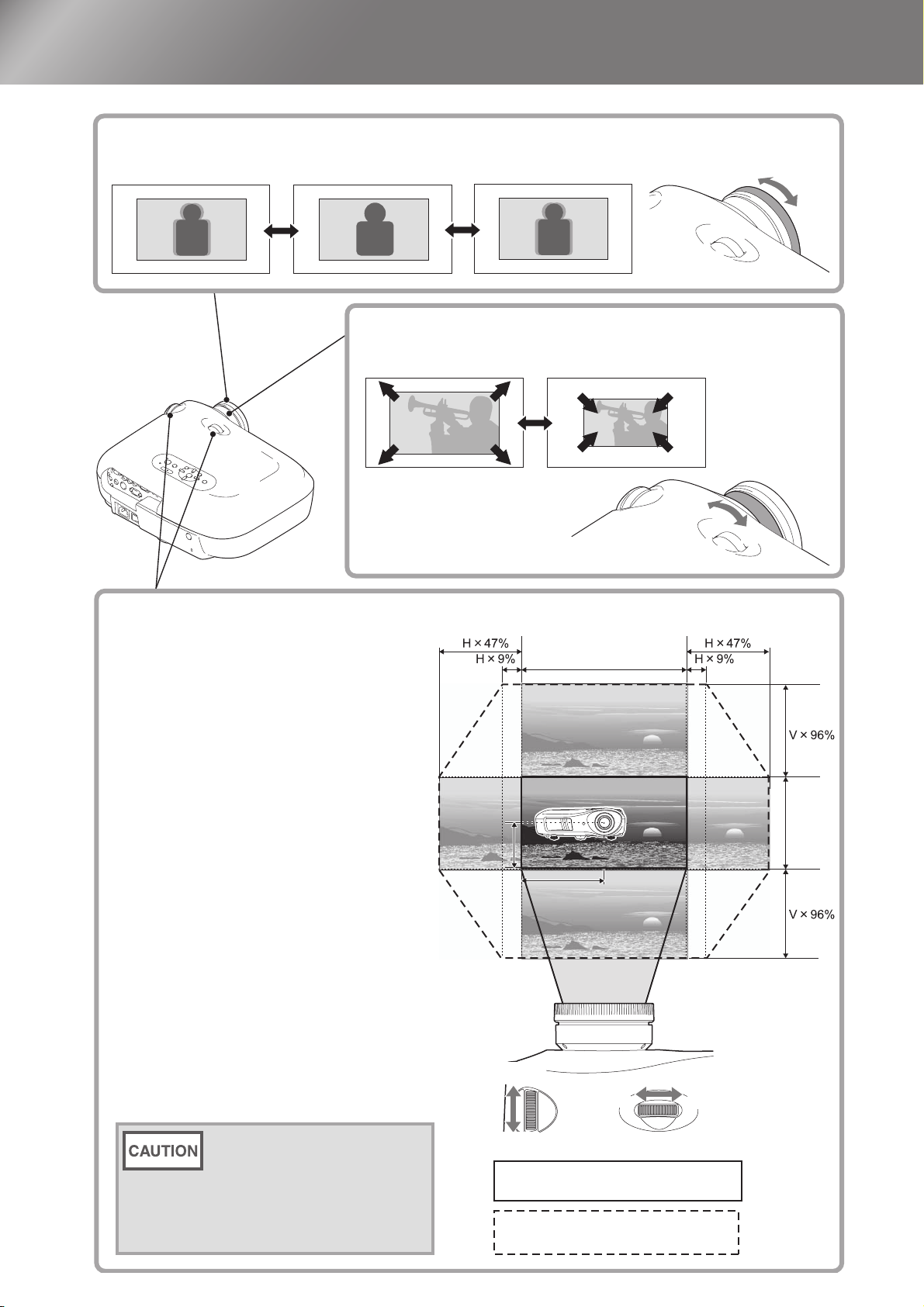
Focus adjustment
Turn the focus ring to adjust the focus.
Fine adjustments to image size (Zoom adjustment)
Turn the zoom ring to adjust the size of the projected image.
Focus adjustment
Projection image position adjustment (Lens shift)
The lens shift function can be used to move
the image display position vertically and
horizontally within the range shown in the
figure on the right when you cannot set up
this projector directly in front of the screen,
or when the image is projected too low or
too high.
When you turn the lens shift dial and hear a
click, the lens position is almost centred.
The image display position cannot be
moved to the maximum positions in both
the vertical and horizontal positions.
Ex) The image cannot be shifted
vertically when it has been shifted
horizontally by the full amount.
When the image has been shifted
vertically by the full amount, it can
be shifted up to 9% of the horizontal
width of the screen.
Fine adjustments to image size (Zoom
adjustment)
Projection image position adjustment
(Lens shift)
1/2V
Wide
Te le
H
V
1/2H
16
When transporting the
projector, make sure to turn the
lens position down by the full
amount. Otherwise the lens
shift mechanism may be
damaged.
Move
downwards
Move
upwards
Standard projection position
(centre position for lens shift)
Range that the picture can be shifted
from the standard projection position
Move to
the left
Move to
the right
Page 19
Adjusting the Projection Screen
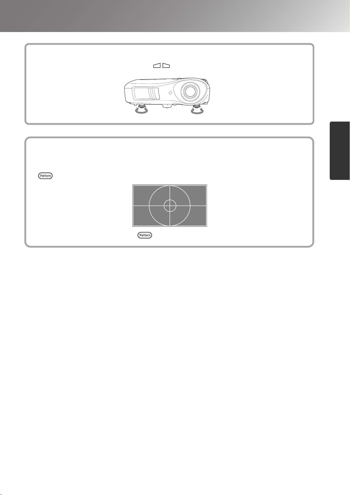
Correcting projector tilt
If the projected images are tilted horizontally ( ), use the front adjustable feet to adjust the projector
so that it is horizontal.
Extend ExtendRetract Retract
Displaying a test pattern
You can project a test pattern at times such as when setting up the projector in order to perform
adjustments in the line menu, and zoom and focus adjustments without having to connect video equipment.
If on the remote control is pressed, the test pattern appears.
Correcting projector tilt
To stop displaying the test pattern, press again.
Displaying a test pattern
Basic Operations
17
Page 20
Basic Image Quality Adjustments
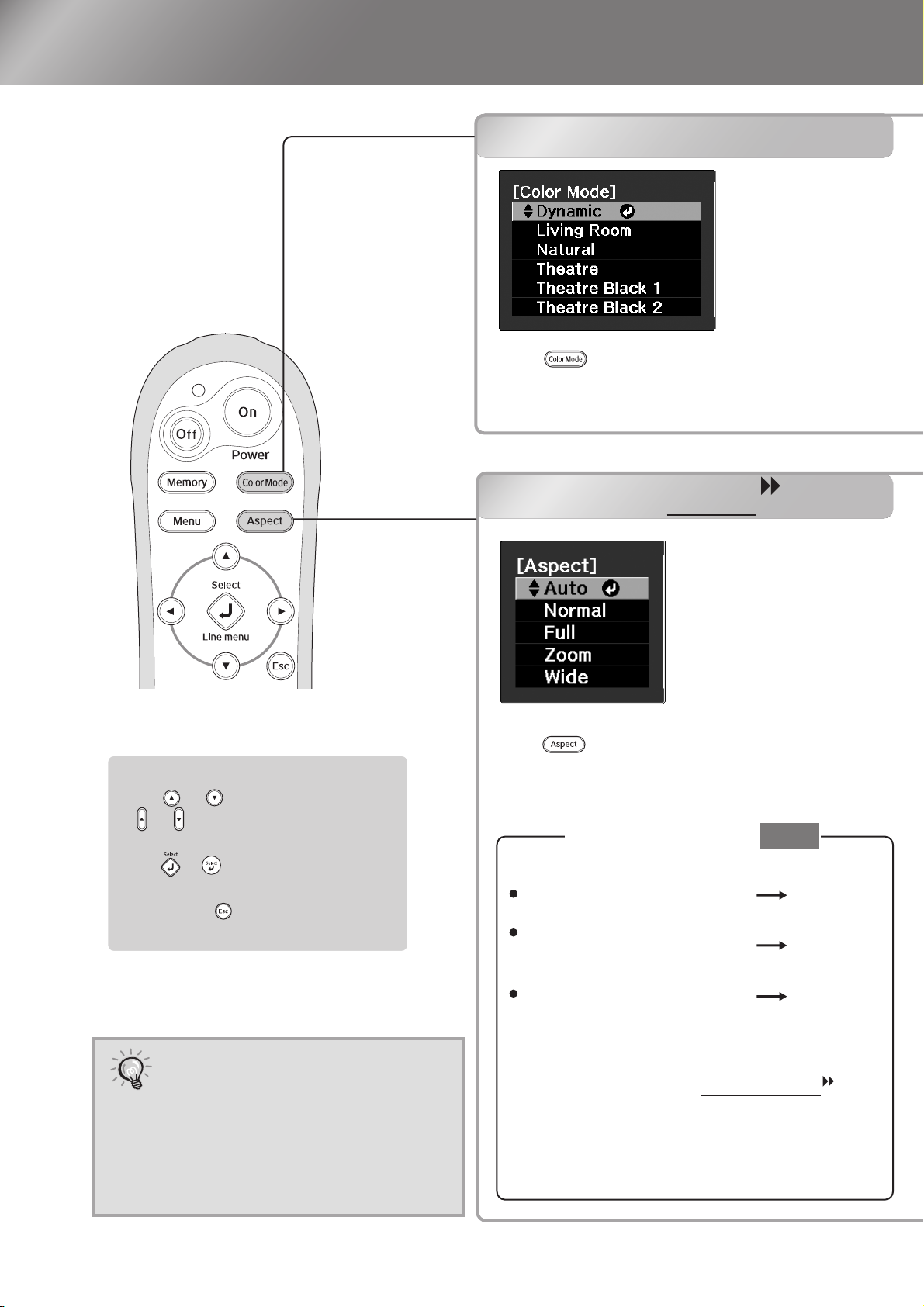
Selecting the colour mode
Selecting the colour mode
Press and select the colour mode from
the menu.
Setting is also possible using the configuration
menu.
Selecting the aspect
Selecting the aspect
Select Menu Operations
Press or on the remote control
or on on the projector's control
panel to select an item.
Press or to confirm the
selection.
*If you press , the Select menu
disappears.
If you project an image that is
compressed, enlarged or separated
TIP
using the aspect function in public
places such as a store or hotel for
the purposes of profit-making or
public display, it may result in
infringing on the author's right that
is protected by copyright law.
Press and select the aspect mode from the
menu.
When projecting using
For 4:3 input signals
For input images recorded
in squeeze mode
For letterbox input signals
*1 Not usable during computer input. Not
compatible with certain component video
signals.
*2 If Auto is not suitable, the setting will become
Normal.
Auto
Normal
Full
Zoom
18
Page 21

Basic Image Quality Adjustments
:
Dynamic
Living Room
Natural
: Ideal for using in bright
rooms.
:
Ideal for using in rooms in
which the curtains are
closed.
:
Ideal for using in dark rooms.
It is recommended that you
Theatre
Black 1
Theatre
Black 2
Suitable for use in a completely
darkened room.
1:
A clear tone of colour one might see in
professional monitors used when
creating DVD software.
2: A deep warm tone of colour that gives
you the feeling of enjoying a movie at
the theatre.
start in this mode when
making colour adjustments.
:
Theatre
Ideal for using in dark rooms.
When you select the colour mode indicated with , the Epson Cinema Filter will be applied
automatically to increase the contrast and makes skin tones more natural.
Input
signal
Recommended
aspect mode
Result
Remarks
Normal TV broadcasts
Images with standard
aspect ratio (4:3)
Computer images
Normal
Black bands will
appear at the left and
right of the images.
When HDTV images
are projected, the
images appear in 16:9
size.
Images recorded by a
video camera or DVD
software in squeeze
mode
Full
Input signals will be
projected at the same
width as the projector's
panel resolution.
When 4:3 images are
projected, the images
will be elongated
horizontally.
Letterbox images
Zoom
Input signals will be
projected at the same
height as the projector's
panel resolution.
When a 4:3 image is
projected, the top and
bottom of the image
are hidden from view.
If this happens, the
part of the image
hidden from view at
the top and bottom can
be reduced in size in
the vertical direction
so that it can be
viewed by "Zoom
Size" in the
Configuration menu.
p.31
When images with
subtitles are projected
and the subtitles are
truncated, use the
"Zoom Caption Pos."
menu command to
adjust. p.31
Normal TV broadcasts
Images with standard
aspect ratio (4:3)
Wide
Input signals will be
projected at the same height
as the projector's panel
resolution. At this time, the
image enlargement ratio
will be smaller near the
middle of the images but
become larger towards the
left and right edges of the
images.
This is useful for when 4:3
images are projected onto a wide
screen. Because there is almost no
distortion due to enlargement in
the middle of the images, the
images appear close to what they
would be at their original size.
And because both ends of the
images are enlarged, movement at
the edges of the images appears
faster and gives an impression of
greater speed, making it ideal for
viewing sporting events.
Image Quality Adjustments
19
Page 22

Advanced Colour Adjustments
If you would like to create your own images with settings adjusted the way you want them, you can
adjust "Abs. Color Temp.", "Skin Tone" and/or "Advanced" in the "Image" menu.
The adjustment values can be stored in the memory so that you can retrieve them and apply them to the
projected images at any time. ( p.24)
"Skin Tone", "Abs.Color Temp." and "Gamma" are adjusted in a single operation using the respective
remote control buttons.
Skin tone adjustment
Skin tone adjustment
Absolute colour temperature
adjustment
Gamma adjustment
Gamma adjustment
Differences between equipment may result in a
slight variation in the colouring when images are
projected, and you may want to adjust this.
(Projection will stop temporarily during such
adjustment.) There are two methods of doing so.
One is to select one of the gamma correction values
[2.0], [2.1], [2.2], [2.3], [2.4]. The other is
customized adjustment, which is done with
reference to the projected image or a gamma graph.
The gamma graph's horizontal axis represents the
input signal level and its vertical axis the output
signal level.
Absolute colour temperature adjustment
Adjusting from the gamma
correction values
From among the gamma correction values [2.0],
[2.1], [2.2], [2.3], [2.4], select one that suits the
connected equipment, or one of your own liking,
using or , and press or to confirm
the selection.
Observe the gamma graph to check the result of the
adjustment.
Lower values will increase the contrast of the dark
portions but will tend to blur the bright portions.
This is indicated by bulging in the upper portion in
the gamma graph.
Higher values will darken the bright portions. This
is indicated by bulging in the lower portion in the
gamma graph.
20
Page 23

Advanced Colour Adjustments
This can be used to adjust the skin tones for images of people.
The Epson Cinema Filter effect that is automatically applied to images when a "Color Mode" setting is
made creates natural-looking skin tones. If you would like to further enhance skin tones, use this "Skin
Tone" setting to make the adjustment.
If set to the + side, the colours become greenish, and if set to the – side, the colours become reddish.
You can adjust the overall tint of images.
If you select a higher value, images appear bluish, and if you select a lower value, images appear reddish.
The absolute colour temperature can be set to one of 12 settings within the range of 5000K to 10000K.
Customized
("Adjust it from the image")
Use or to select first "Customized",
then "Adjust it from the image". Press or
to confirm the selection each time.
A gamma icon will appear in the projected image.
Use or to move the
gamma icon to the place where you want to
adjust the brightness, and press or to
confirm the selection. The place selected and
the regions of the same brightness will flash,
and a gamma graph will appear. Press or
again to reconfirm. A screen for adjusting the
tone will appear.
Use or to make the adjustment, and
press or to confirm it. Press to go
back and do it again.
Customized
("Adjust it from the graph")
Use or to select first "Customized",
then "Adjust it from the graph". Press or
to confirm the selection each time.
A gamma adjustment graph will appear.
Image Quality Adjustments
Use or to select the point where
you want to adjust the tone brightness, and press
or to confirm the selection. A screen for
adjusting the tone will appear.
Use or to make the
adjustment, and press or to confirm it.
21
Page 24

Advanced Colour Adjustments
RGB adjustment (Offset, Gain)
The image brightness can be adjusted by adjusting
the individual R (red), G (green) and B (blue)
components of the dark areas (offset) and bright
areas (gain).
Offset
If you would like dark areas to appear more clearly,
change the setting to the + (right) side. If you
change it to the – (left) side, the whole image will
become sharper, but the contrast in dark areas will
become poorer.
RGB adjustment (Offset, Gain)
Hue and saturation adjustment
Gain
If you would like bright areas to appear more
clearly, change the setting to the – (left) side. If
you change it to the + (right) side, you will feel
that the image is becoming brighter and closer to
white, but the contrast in light areas will become
poorer.
Press and then select "Image" -
"Advanced" - "RGB" in that order and
confirm the selection.
Use or to select a menu
item, and use or to
make adjustments.
To return the adjustment results to their
default settings, press .
Press to exit the menu.
Hue and saturation adjustment
The hue and saturation for each of the red (R),
green (G), blue (B), cyan (C), magenta (M) and
yellow (Y) colour components can be adjusted.
Hue
Adjusts the tone of the entire image to bluish,
greenish and reddish.
Saturation
Adjusts the overall vividness of the images.
Press and then select "Image" -
"Advanced" - "RGBCMY" in that order
and confirm the selection.
Press or to select a colour and
press or to confirm. Select either
hue or saturation and use or
to adjust.
To adjust another colour, press .
To return the adjustment results to their default
settings, press .
Press to exit the menu.
22
Page 25

Examining Image Quality Further
In addition to colour adjustments, adjustments to advanced sharpness and the amount of light from the
lamp can also be made to match the image in search of the best picture.
Sharpness (Advanced) adjustment
This cannot be adjusted during input of computer
image signals.
If "High-band Enhancement" is set in the +
direction, hair and the detailed areas of clothing
will be emphasized.
If "Low-band Enhancement" is set in the +
direction, the areas emphasized by "High-band
Enhancement" will be hardly emphasized. Instead,
the rough areas of the entire subject, such as
contour and background, will be emphasized,
resulting in a sharp image.
Setting "Horiz. Line Enhancement" / "Vert. Line
Enhancement" to the + side will enhance the
image sharpness in the horizontal / vertical
direction. Setting them to the - side will give a soft
image.
Sharpness (Advanced) adjustment
Auto Iris (automatic aperture) setting
Press , and then select "Image" -
"Sharpness". Select "Advanced" at the
top-right corner of the screen to confirm
the selection.
Use or to select a menu item,
and use or to make
adjustments.
You can adjust "High-band Enhancement" and
"Low-band Enhancement" at the same time by
using the bar on the top in the screen.
To return the adjustment results to their default
settings, press .
Press to exit the menu.
Auto Iris (automatic aperture) setting
When "Auto Iris" is set to "On", the amount of
light will be automatically adjusted to the
brightness of the image, creating a picture with
depth and perspective.
*
An operation sound of Auto Iris function may
be emitted while projecting some images. This
is not a failure of the projector.
Press , and then select "Image" -
"Auto Iris".
Select "On".
Press to exit the menu.
Image Quality Adjustments
23
Page 26

Viewing Images at a Preset Image Quality(Memory Function)
After menu commands such as "Image" has been used to adjust the projected images, the adjustment
values can then be saved (Save Memory).
In addition, the saved data can be retrieved easily, so that you can enjoy viewing images with the
adjusted settings at any time (Load Memory).
Saving, Loading and Erasing
Viewing Images at a Preset Image
Quality (Save Memory)
Memory
Saving, Loading and Erasing Memory
The adjustments that can be saved to memory are as
follows.
Up to ten adjustments can be saved to memory.
Color Mode
Brightness
Image
Contrast
Color Saturation
Tint
Sharpness
Abs. Color Temp.
Skin Tone
Advanced
Brightness Control
Auto Iris
Standard
Advanced
Gamma
RGB
RGBCMY
24
Displayed for input sources other than computer
Page 27

Viewing Images at a Preset Image Quality(Memory Function)
Save Memory
Adjust each of the settings to the values
to be saved.
Press , and select "Save
Memory".
The Save Memory screen is displayed.
Select the memory name to register the
adjustments to from Memory1 to 10, and
press or .
When preceding the memory name is
green, this indicates that adjustments are
already saved to memory.
Select an already saved memory name, and
press or .
A confirmation message will be displayed.
If you select "Yes", the previous memory
content is erased, and the current adjustment
values are saved.
The colour mode selected
when the memory was
TIP
registered is displayed on the
right side.
Memory settings that have
been applied to images will be
retained even when the
projector's power is turned off.
The same memory adjustment
settings will be applied to
images that are projected the
next time the projector's power
is turned on.
The aspect setting retrieved
from memory may not be
applied to the images if they
are 16:9 images or if the input
signal images have a particular
resolution.
Erase Memory
This feature can be used to erase and clean up
unwanted memories.
Press , and select "Erase Memory".
The Erase Memory screen will be displayed.
Load Memory
Load saved memories.
Press , and select "Load Memory".
The Load Memory screen will be displayed.
Select the target memory name.
Select the memory name to erase.
A confirmation message will be displayed. If
you select "Yes", the memory will be erased.
To erase all saved memories, select "Reset" "Reset Memory" in the Configuration menu.
p.35
Image Quality Adjustments
25
Page 28

Configuration Menu Functions
The configuration menus can be used to make a variety of adjustments and settings involving image
quality and input signals.
The following two types of menu are available.
■ Full menu
All items in the configuration menu can be checked
while the settings are being made.
Top menu Sub-menu
Refer to "Using the configuration menus"( p.26) for details on menu operations.
The Configuration menu can be used to change the colour pattern and display position of
the menus.
TIP
"Settings" - "Display" - "Menu Position", "Menu Color"
■ Line menu
Some of the items in the "Image" menu in the
Configuration menu can be adjusted.
This menu is useful for viewing the effects of
adjustments in the images being projected while the
adjustments are being made.
Navigation Bar
Using the configuration menus
Displaying a menu
Full menu: Press . Line menu: Press or .
Selecting a menu item
Use or to select a menu item, then press .
26
Page 29

Configuration Menu Functions
Changing settings
Example:
Use or to adjust values.
(green): Current setting value
Use or to select an item, then press .
If you press when an item with next to it is selected, the selection screen for that item
will be displayed.
To return to a previous display, press .
When setting is complete
Press .
27
Configuration Menu
Page 30

Configuration Menu Functions
List of configuration menus
When no image signals are being input, the
Also, the items displayed in the
"Image"
"Image"
menu and the
menu, the
"Signal"
depending on the type of image signals that are being projected.
Displayed for input sources other than computer * This is displayed in the line menu.
Color Mode
Brightness
Image
Contrast
Color Saturation
Tint
Sharpness
Abs. Color Temp.
Skin Tone
Advanced
Brightness Control
Auto Iris
Reset
p.30
p.30
p.30
p.30
p.30
p.30
p.30
p.30
p.30
p.31
p.31
p.31
Dynamic, Living Room, Natural, Theatre,Theatre Black 1, Theatre Black 2
*
*
*
*
*
*
*
High, Low
On, Off
Yes, No
Standard
Advanced
Gamma
RGB
RGBCMY
"Signal"
menu and the
Thin Line Enhancement, Thick Line Enhancement
Vert. Line Enhancement, Horiz. Line Enhancement
2.0
Customized
menu cannot be adjusted.
"Info"
menu will vary
,
2.1, 2.2, 2.3, 2.4
Adjust it from the image
Adjust it from the graph
Reset
Offset R, G, B
Gain R, G, B
R (Hue/Saturation), G (Hue/Saturation),
B (Hue/Saturation), C (Hue/Saturation),
M (Hue/Saturation), Y (Hue/Saturation)
Displayed for input sources other than computer
Aspect
Zoom Size
Signal
Zoom Caption Pos.
Tracking
Sync.
Position
Auto Setup
Progressive
Motion Detection
Noise Reduction
Output Scaling
Setup Level
EPSON Super White
p.31
p.31
p.31
p.31
p.31
p.31
p.31
p.32
p.32
p.31
p.32
p.31
p.32
p.32
p.32
Only displayed for Computer input
(does not appear when signals from the [HDMI] input port are being input)
Auto, Normal, Full, Zoom, Wide
On, Off
Off, Video, Film/Auto
Off, NR1, NR2, NR3
Auto, 100%, 98%, 96%, 94%, 92%
0%, 7.5%
On, Off
28
HDMI Video Range
Reset
p.33
p.33
Normal, Expanded
Yes, No
Page 31

Configuration Menu Functions
Direct Power On
Sleep Mode
Settings
Child Lock
Operation Lock
Trigger Out
High Altitude Mode
Projection
Display
Input Signal
p.34
p.34
p.33
p.33
p.33
p.33
p.33
p.33
p.34
Off, 5min., 10min., 30min.
Menu Position
Center-right, Bottom-left, Bottom-center, Bottom-right
Menu Color
Messages
Display Background
Startup Screen
Video Signal
On, Off
On, Off
On, Off
On, Off
On, Off
Front, Front/Ceiling, Rear, Rear/Ceiling
Top-left, Top-center, Top-right, Center-left, Center,
Color 1, Color 2
On, Off
Black, Blue, Logo
On, Off
Auto, NTSC , NTSC4.43, PAL ,
M-PAL, N-PAL, PAL60, SECAM
Language
Reset
Lamp Hours
Info
Source
Input Signal
Resolution
Scan Mode
Refresh Rate
Sync Info
Video Signal
Component
D/SCART
p.34
p.33
Only displayed for composite video/S-Video input
Only displayed for component video/Computer input
p.35
The message text will be displayed in yellow when it is time to replace the lamp.
Time from 0H to 10H will be displayed as 0H. From 10H onwards, the display will be in units of 1H.
Resolution
Sync Info
The "Info" menu is only used to display the projector status.
Auto, YCbCr , YPbPr
D(Auto), D(YCbCr), D(YPbPr), SCART
Yes, No
Only displayed for Computer input
Configuration Menu
Deep Color
Status
Load Memory
Save Memory
Memory
Erase Memory
p.35
p.35
p.35
Display the color depth of HDMI transmission.
This is information about errors that have occurred on the projector.
This value is sometimes referred to when inquiries are made.
Memory1 to Memory10
Memory1 to Memory10
Reset All
Reset Memory
Reset
Memory1 to Memory10
Reset Lamp Hours
p.35
Yes, No
p.35
Yes, No
p.35
Yes, No
29
Page 32

Configuration Menu Functions
"Image" menu
Displayed for input sources other than computer
Color Mode
*1
Six different settings can be selected for the Color Mode, to match the images being projected or the
projection environment. p.18
Brightness
*2
Adjust this when the output level of the connected equipment is weak and you feel that images are dark.
Contrast
*2
Adjusts the difference between bright and dark areas.
When the contrast is increased, images with greater modulation are obtained.
Color Saturation
*2
This adjusts the colour intensity for the images.
*2
Tint
(Adjustment is only possible when composite video
and S-Video signals in NTSC format are being
input.)
This adjusts the image tint.
Sharpness
*2
This adjusts the image sharpness.
Standard
The adjustment results are applied to the entire image.
Advanced
This can be used to adjust a specific region. p.23
Abs. Color Temp.
This adjusts the overall tints of the images.
Skin Tone
*2
*2
p.20
This adjusts the skin tones of people who appear in the images. p.20
Advanced
Gamma
This adjusts gamma. You can select a value, or make adjustments while viewing an image or a graph.
RGB
This lets you adjust the offset and gain for each of the R/G/B colour components. p.22
*1
p.20
*1
30
RGBCMY
*1
This lets you adjust the hue and saturation for each of the R/G/B/C/M/Y colour components. p.22
*1 The setting values are stored separately for each image source and signal type.
*2 The setting values are stored separately for each image source and colour mode setting.
Page 33

Configuration Menu Functions
Only displayed for Computer input
(does not appear when signals from the [HDMI] input port are being input)
Brightness Control
This lets you set the lamp brightness to one of two settings.
Select "Low" if the images being projected are too bright such as when projecting images in a dark room
or onto a small screen. Use of "Low" prolongs the life of the lamp, and reduces the amount of power and
noise produced by fan rotation during projection.
*2
Auto Iris
The amount of light is adjusted appropriately depending on images (On)/ or not adjusted (Off). p.23
*3
Reset
This returns all settings in the "Image" menu to their default settings.
"Signal" menu
Aspect
Selects the aspect mode. p.18
Zoom Size
This can be set only when "Aspect" is set to "Zoom".
This function enables the image to be reduced in size in the vertical direction so that the top and bottom
of images that are hidden from view can be viewed when "Zoom" is set. The larger the adjustment value
(reduction ratio) set here, the more the image is compressed and displayed squashed in the vertical
direction.
Zoom Caption Pos.
*1
*1
*1
This can be set only when "Aspect" is set to "Zoom".
This function moves the display position of the image in one direction, up or down, to display captions
when projecting images with captions.
Tracking
This adjusts the images if vertical stripes appear in the images.
Sync.
This adjusts the images if flickering, fuzziness or interference appear in the images.
• Flickering and fuzziness may also occur when the brightness, contrast
adjusted.
• Clearer adjustments can be obtained if you adjust the "Tracking" first and then adjust the "Sync".
Position
(Setting is not possible when signals are being input from the [HDMI] input port.)
When part of the image is clipped, move the image display position vertically and horizontally so that the
entire image is projected. Press , , and to adjust the position.
*1
*1
and sharpness settings are
*1
Auto Setup
This sets automatic adjustment to on or off in order to set whether the projector automatically adjusts
images to their optimum condition when the input signal is changed. The three automatically adjusted
items are "Tracking", "Position" and "Sync."
Configuration Menu
*1 The setting values are stored separately for each image source and signal type.
*2 The setting values are stored separately for each image source and colour mode setting.
*3 The setting values are stored separately for each colour mode setting.
31
Page 34

Configuration Menu Functions
Progressive
(This can be set only when signals are being input from the [Video] / [S-Video] input port, 525i, 625i
signals are being input from the [SCART] input port, or 525i, 625i, 1125i signals are being input from
the [Component] / [HDMI] input port.)
Interlace
• Off :This is ideal for using when viewing images with a large amount of movement.
• Video :This is ideal for general video images.
• Film/Auto :By pulling down 3-2
*1
(i) signals are converted to progressive (p) signals using a method appropriate for the image.
frames are automatically converted to the optimum progressive signals so that images are
reproduced looking natural as originally intended.
Displayed for input sources other than computer
/2-2, images (e.g. video films/CG or animations) recorded in 24/30
Motion Detection
*1
(This can be set only when signals are being input from the [Video] / [S-Video] input port, 525i, 625i
signals are being input from the [SCART] input port, or 525i, 625i, 1125i signals are being input from
the [Component] / [HDMI] input port.)
Select whether the progressive conversion operation mode is for fast-moving images or for slow-moving
images. The smaller the value, the more suitable the mode is for viewing still images. The larger the
value, the more suitable the mode is for viewing video images.
Noise Reduction
*1
This reduces flickering of images.
Three modes are available. Select the mode to suit your liking.
Set "Off" when the image source, such as DVD, contains little electrical interference.
Output Scaling
(Setting is not possible when composite video
*1
, S-Video , or computer signals are being input.)
This changes the display area (the part of projected images).
• 100% - 92% :When 100% is set, the top and bottom of the image is sometimes affected by electrical
interference depending on the image signal. In such cases, try to adjust the display
position ("Position"). p.31
• Auto :Displayed when the signals from [HDMI ] input port are being input. Signals are
automatically projected at 100% or 92% size depending on the input signals. (Not displayed
when the equipment's DVI port is connected to the projector's [HDMI] input port.)
32
Setup Level
*1
(This can be set when NTSC signals are being input from the [Video] / [S-Video] input ports, when
composite video signals are being input from the [Component] input port, or when signals are being
input from the [SCART] input port.)
If using products designed for destinations such as South Korea that have different black level (setup
level) settings, use this function to obtain correct images. Check the specifications of the connected
equipment when changing this setting.
EPSON Super White
(
Setting is only possible when Color Mode is "Natural", "Theatre", "Theatre Black 1", or "Theatre Black
*1
2", and composite video, S-video, component video, or SCART signals are being input.)
If bright white areas of images such as clouds and T-shirts on the beach in summer appear uneven and
overexposed, set to "On". When set to "On", the "HDMI Video Range" setting will be ignored.
*1 The setting values are stored separately for each image source and signal type.
Page 35

Configuration Menu Functions
Displayed for input sources other than computer
HDMI Video Range
(Setting is possible only when "EPSON Super White" is "Off".)
When the [
range of the projector to suit the video range setting of the DVD player. The setting at the DVD player
can be either Normal or Expand.
HDMI
*1
] input port of the projector is connected to a DVD player, for example, set the video
Reset
All the adjustment values on the "Signal" menu, except "Aspect
", are returned to their default values.
"Settings" menu
Direct Power On
When the main power switch is turned on, you can set for projection to start (On) / not start (Off) without
pressing or .
When set to "On" with the main power switch left on, be aware that sudden surges of electricity that may
occur when the power comes back on after a power outage may cause the projector to turn on.
Sleep Mode
The projector is equipped with a power-saving function that causes the power to turn off automatically
and the projector to switch to standby if no signal is input to the projector for a continuous length of time.
The length of time before the power-saving function operates can be selected from four available settings.
If "Off" is selected, the power-saving function will not operate.
If you press while the projector is in standby mode, projection will start again.
Child Lock
This locks the power on function of the button on the projector's control panel, so that a child cannot
accidentally turn the projector's power on and look into the projector's lens. When the lock is applied, the
power will only turn on if is pressed down for about 3 seconds. can be used to turn off the power,
and the remote control will continue to operate as normal.
If you change the setting, the new setting will take effect after the power has been turned off and the cooldown period is complete.
Even if "Child Lock" is set to "On", be aware that projection starts merely by turning the main power
switch on when "Direct Power On" is set to "On".
Operation Lock
If this is set to "On", you can't operate the projector's control panel buttons and a icon appears on the
screen when a button is pressed. To cancel, press and hold
seven seconds or more.
If you change the setting, the new setting will take effect after exiting the configuration menu.
on the projector's control panel for about
Trigger Out
This turns the trigger function on and off to determine whether the projector's power on/off status and
problems with projector operation are communicated to an external device.
If you change the setting, the new setting will take effect after the power has been turned off and the cooldown period is complete.
High Altitude Mode
A fan is set at a certain speed of rotation so as to bring down internal temperature.
When using above an altitude of about 1500m, set to "On".
*1 The setting values are stored separately for each image source and signal type.
Configuration Menu
33
Page 36

Configuration Menu Functions
Projection
This should be set in accordance with the method used to set up the projector.
• Front : Select when the projector is set up in front of the screen.
• Front/Ceiling : Select when the projector is set up in front of the screen and suspended from a ceiling.
• Rear : Select when the projector is set up behind the screen.
• Rear/Ceiling :
Select when the projector is set up behind the screen and suspended from a ceiling.
Display
Menu Position
Press , , and to specify the position for the menus to be displayed.
Menu Color
Selects the color for the main configuration menu.
• Color 1:Black • Color 2:Blue
Messages
This sets whether the following message displays appear (On) or don't appear (Off).
• Image signal, colour mode, aspect
• Messages such as when no image signals are being input, when an incompatible signal is input, and
when the internal temperature rises.
and item name when memory settings are retrieved.
Display Background
Displays a menu for selecting the screen status for when using the blank function or when no image
signal is input.
Startup Screen
This sets whether the start-up screen (the image that is projected when projection starts) is displayed (On)
or not displayed (Off).
If you change the setting, the new setting will take effect after the power has been turned off and the cooldown period is complete.
Input Signal
Video Signal
Sets the signal format in accordance with the video equipment that is connected to the [Video] or [SVideo] input port. If set to "Auto", the video signal format is set automatically.
If there is a lot of interference in the image, or if a problem such as no image being projected occurs even
though "Auto" has been selected, select the correct signal format manually.
Component
Change this setting depending on the type of signal that is being output from the video equipment that is
connected to the [Component] input port.
If "Auto" is selected, appropriate signal is automatically set. If colours appear unnatural even though
"Auto" is selected, select appropriate signal name in the menu.
34
D/SCART
This sets the signal format in accordance with the signals being output from video equipment that is
connected to the [SCART] port (in Europe) or [D] port (in Japan).
Language
This sets the display language for messages and menus.
Page 37

Configuration Menu Functions
Reset
Adjustment values for the "Settings" menu functions are returned to their default settings, except for the
"High Altitude Mode", "Projection", "Component", "D/SCART", and "Language".
"Memory" menu
Load Memory
This retrieves settings previously saved using "Save Memory". p.24
This cannot be selected when nothing is saved at "Save Memory".
Save Memory
This can be used to save "Image" menu settings. p.24
Erase Memory
This is used to erase unwanted saved memory. p.24
"Reset" menu
Reset All
This resets all configuration menu settings to their default settings. "Component", "D/SCART" and
"Language" in the "Settings" menu, and the settings of "Memory" menu are not returned to their default
even if "Reset All" is executed.
Reset Memory
This resets (erases) all settings that have been made using the "Save Memory".
Reset Lamp Hours
Clear the cumulative lamp operating time and reset to "0H". Perform this procedure when you replace
the lamp.
35
Configuration Menu
Page 38

Problem Solving
(
Reading the indicators
The projector is provided with the following two indi-
operation) indicator
cators which notify you of the operating status of the
projector.
The following tables show what the indicators mean
and how to remedy the problems that they indicate.
* If all indicators are switched off, check that the
power cable is connected correctly and that the
(warning) indicator
main power switch is on.
When the (warning) indicator is lit or flashing
Internal problem / Fan problem / Sensor problem / Cinema filter problem /
Red
Auto iris problem
Disconnect the power cable from the electrical outlet. Then contact your local
(Lit/off for
1 sec)
Red
Lamp problem / Lamp on error / Lamp cover open error
Check if the lamp is broken. p.46
Clean the air filter. p.44
dealer or the nearest address provided in the
Inquiries
World-Wide Warranty Terms
warning/problem
: Lit : Flashing
.
(Lit/off for
0.5 sec)
If the lamp is
not broken
If the lamp is
broken
Check that the lamp and the lamp cover are securely installed.
When using above an altitude of about 1500 m, make sure you set the "High Altitude Mode" to
"On". p.33
High internal temperature
Red
(overheating)
The lamp will switch off
automatically and projection will
stop. Wait for approximately 5
minutes. When the cooling fan
stops, turn off the main power
switch at the rear of the projector.
Orange
High-speed cooling in
progress
You can continue using the
projector, but if the temperature
rises again, it will switch off
automatically.
Replace the lamp
and then turn the
power on.
Contact your local dealer for further advice.
If the problem is still not solved after the lamp is
replaced, stop using the projector and disconnect the
power cable from the electrical outlet. Then
your local dealer or the nearest address provided
in the
World-Wide Warranty Terms
• If the projector is
installed against a
wall, leave a space
of 20 cm or more
between it and the
wall.
• Clean the air filters
if they are blocked.
p.44
If the problem is not solved
when the power is turned
back on, stop using the
projector, turn off the main
power switch, and
disconnect the power
cable from the electrical
outlet. Then
local dealer or the nearest
address provided in the
World-Wide Warranty
Te r ms
. Inquiries
contact your
. Inquiries
contact
36
Page 39

Problem Solving
When the (operation) indicator is lit or flashing
When the (warning) indicator is off : Lit : Flashing
Orange
Green
Green
Orange
Standby condition
Warm-up in
progress
Projection in
progress
Cool-down
progress
in
If you press , projection will start after a brief interval.
Warm-up time is approximately 30 seconds.
Power off operations are ignored while warm-up is in progress.
Normal operation is in progress.
Cool-down time is approximately 30 seconds.
After cool-down is complete, the projector goes to standby mode.
You cannot use the remote control or the projector's control panel
during cool-down.
If the main power switch at the rear of the projector is turned off before
cool-down is complete, wait for the lamp to cool down (normally about
one hour is required) before turning the power back on again.
normal
When the indicators provide no help
If any of the following problems occur and the indicators do not offer a solution, refer to the pages
given for each problem.
Problems relating to images
● No images appear p.38
Projection does not start, the projection area is
completely black, the projection area is
completely blue, etc.
● Moving images are not displayed
p.38
Moving images played on computer are not
displayed.
● The message "Not Supported" is
displayed p.39
● The message "No Signal" is displayed
p.39
● Images are fuzzy or out of focus p.39
● Interference or distortion appear in
images p.40
● Image is truncated (large) or
small p.40
Only part of the image is displayed.
● Image colours are not right p.41
The whole image appears purplish or
greenish, images are black & white, colours
appear dull, etc.
(Computer monitors and LCD screens have
different colour reproduction performance, so
that the colours projected by the projector and
the colours appearing on the monitor may not
necessarily match, but this is not a sign of a
problem.)
● Images appear dark p.41
● Projection stops automatically p.42
Problems such as interference, distortion or
black & white checked patterns appear.
Problems when projection starts
● Power does not turn on p.43 ● The remote control does not
Problems with the remote control
work p.43
Troubleshooting
37
Page 40

Problem Solving
Problems relating to images
■ No images appear
Have you pressed the [Power]
button?
Is the main power switch
turned off?
Are all of the indicators
switched off?
Is blank mode active? Press on the remote control to cancel the blank function.
Is a video signal being input? Check that the power for the connected equipment is turned on. If
Are the image signal format
settings correct?
Press on the remote control or on the projector’s control
panel.
Turn on the main power switch at the rear of the projector.
Disconnect the power cable and then reconnect it. p.14
Check the circuit breaker to see if power is being supplied.
the "Messages" menu command has been set to "On", messages
relating to the image signals will be displayed.
"Settings" - "Display" - "Messages" p.34
If a composite video
If projection does not occur when the "Video Signal" menu
command is set to "Auto", select the signal format that matches the
signal source.
"Settings" - "Input Signal" - "Video Signal" p.34
If the signal source is connected to the [Component] or [D] input
port
If projection does not occur when the "Component" in the "Input
Signal" menu command is set to "Auto", set the signal format that
matches the signal that is being projected from the connected
equipment.
"Settings" - "Input Signal" - "Component" p.34
or S-Video signal is being input
Å
If the VCR or DVD equipment is connected using a D SCART
adapter
Press to set the signal format to "D/SCART". p.15
When still no images appear and the DVD equipment is connected,
change the setting at the DVD equipment to RGB output.
Have the configuration menu
settings been made correctly?
Were the projector and computer
connected while their power was
already turned on?
When a computer is
connected
■ Moving images are not displayed
Is the computer image signal set
to output simultaneously both
externally and to the LCD
monitor?
Only when projecting images
from a laptop computer or
computer with a built-in LCD
screen
Try resetting all of the current settings. p.35
If the connection is made while the power is already turned on, the
function [Fn] key that switches the computer's video signal to
external output may not work. Turn the power for the computer that
is connected to the projector off and then back on again.
Set the image signal to output only externally.
output" or "Connecting an external monitor"
Computer documentation, under a title such as "External
38
Page 41

■ The message "Not Supported" is displayed
Problem Solving
Are the image signal format
settings correct?
If a composite video or S-Video is being input
If projection does not occur when the "Video Signal" menu
command is set to "Auto", select the signal format that matches the
signal source.
"Settings" - "Input Signal" - "Video Signal" p.34
If the signal source is connected to the [Component] or [D] input
port
If projection does not occur when the "Component" in the "Input
Signal" menu command is set to "Auto", set the signal format that
matches the signal that is being projected from the connected
equipment. "Settings" - "Input Signal" - "Component" p.34
Does the mode match the
frequency and resolution of the
image signals?
Only when projecting
computer images
Use the "Resolution" menu command to check the signals being
input, and check the "List of Supported Monitor Displays" to make
sure that the signals are compatible.
"Info" - "Resolution" p.29
"List of Supported Monitor Displays" p.49
■ The message "No Signal" is displayed
Are the cables connected
correctly?
Check that all of the cables required for projection are securely
connected. p.12
Has the correct video input port
been selected?
Is the power for the connected
equipment turned on?
Are the image signals being
output to the projector?
Only when projecting
images from a laptop
computer or computer
with a built-in LCD
screen
■ Images are fuzzy or out of focus
Has the focus been adjusted
correctly?
Is the lens cover still attached?
Press , , , or on the remote control or
on the projector’s control panel to change the image source.
p.15
Turn the power on for the devices.
If the image signals are only being output to the computer's LCD
monitor, you need to change the output.
For some computer models, when the image signals are output
externally, they no longer appear on the LCD monitor.
Computer documentation, under a title such as "External
output" or "Connecting an external monitor"
If the connection is made while the power is already turned on, the
function [Fn] key that switches the computer's video signal to
external output may not work. Turn the power for the projector and
the computer off and then back on again. p.14
Adjust the focus. p.16
Remove the lens cover.
Is the projector at the correct
distance?
The recommended distance from the projector to the screen is
within 87 to 956 cm (2.8 to 31.4 ft.) for a screen size of 16:9, and
106 to 1170 cm (3.5 to 38.4 ft.) for a screen size of 4:3. Set up the
projector so that the projection distance is within this
range. p.10
Troubleshooting
39
Page 42

Problem Solving
Has condensation formed on the
lens?
If the projector is suddenly taken from a cold environment to a
warm environment or if sudden ambient temperature changes
occur, condensation may form on the surface of the lens, and this
may cause the images to appear fuzzy. Set the projector up in the
room approximately one hour before it is to be used. If
condensation forms on the lens, turn the power off and wait for the
condensation to disappear.
■ Interference or distortion appear in images
Are the image signal format
settings correct?
If a composite video or S-Video is being input
If projection does not occur when the "Video Signal" menu
command is set to "Auto", select the signal format that matches the
signal source.
"Settings" - "Input Signal" - "Video Signal" p.34
If the signal source is connected to the [Component] or [D] input
port
If projection does not occur when the "Component" in the "Input
Signal" menu command is set to "Auto", set the signal format that
matches the signal that is being projected from the connected
equipment. "Settings" - "Input Signal" - "Component" p.34
Are the cables connected
correctly?
Check that all of the cables required for projection are securely
connected. p.12
Is an extension cable being
used?
Have the "Sync. " and
"Tracking
adjusted correctly?
Has the correct resolution been
selected?
" settings been
Only when projecting
computer images
Only when projecting
computer images
If an extension cable is used, interference may increase. Try
connecting a signal amplifier.
The projector has an automatic adjustment function that causes the
optimum images to be projected. However, for some types of
signal, the correct adjustments may not be obtained even after
automatic adjustment is carried out. In such cases, use the
"Tracking" and "Sync." menu commands to make the adjustments.
Set the computer so that the signals that are output are compatible
with this projector.
■ Image is truncated (large) or small
Has the correct aspect been
selected?
Press to select the aspect that corresponds to the input
signal. p.18
If images with subtitles are being projected using "Zoom", use the
"Zoom Caption Pos." menu command to adjust the images.
"Signal" - "Tracking", "Sync." p.31
"List of Supported Monitor Displays" p.49
Computer documentation
p.31
40
Has the "Position" setting been
adjusted correctly?
Has the computer been set for
dual display?
Only when projecting
computer images
Use the "Position" the menu command to make the adjustment.
"Signal" - "Position" p.31
If dual display has been activated in the Display Properties of the
computer's Control Panel, the projector will only project about half
of the image on the computer screen. To display the whole of the
image on the computer screen, turn off the dual display setting.
Computer video driver documentation
Page 43

Problem Solving
Has the correct resolution been
selected?
Only when projecting
computer images
■ Image colours are not right
Are the image signal format
settings correct?
Are the cables connected
correctly?
Set the computer so that the signals that are output are compatible
with this projector.
"List of Supported Monitor Displays" p.49
Computer documentation
If a composite video or S-Video is being input
If projection does not occur when the "Video Signal" menu
command is set to "Auto", select the signal format that matches the
signal source.
"Settings" - "Input Signal" - "Video Signal" p.34
If the signal source is connected to the [Component] or [D] input
port
If projection does not occur when the "Component" in the "Input
Signal" menu command is set to "Auto", set the signal format that
matches the signal that is being projected from the connected
equipment. "Settings" - "Input Signal" - "Component" p.34
Check that all of the cables required for projection are securely
connected. p.12
Has the image contrast
been adjusted correctly?
Has color been adjusted
appropriately?
Have the colour intensity and
tint been adjusted correctly?
Only when projecting
images from a video
source
■ Images appear dark
Has the image brightness been
adjusted correctly?
Has the image contrast
been adjusted correctly?
Is the lamp due for
replacement?
Use the "Contrast" menu command to adjust the color.
"Image" - "Contrast"
p.30
Use the "Advanced" menu command to adjust the colour.
"Image" - "Advanced"
p.30
Use the "Color Saturation" and "Tint" menu commands to adjust
the colour and tint.
"Image" - "Color Saturation", "Tint" p.30
Use the "Brightness" menu commands to make the adjustments.
"Image" - "Brightness" p.30
Use the "Contrast" menu command to adjust the color.
"Image" - "Contrast"
p.30
When the lamp is nearly due for replacement, the images will
become darker and the colour quality will become poorer. When
this happens, the lamp should be replaced with a new one. p.46
41
Troubleshooting
Page 44

Problem Solving
■ Projection stops automatically
Is sleep mode active?
When "Sleep Mode" has been set to On, the lamp turns off
automatically if no signal is input for about 30 minutes, and the
projector switches to standby mode. Press the button on the
remote control or the button on the projector's control panel to
turn the projector's power back on. To cancel the sleep mode
setting, change "Sleep Mode" menu command to "Off".
"Settings" - "Sleep Mode" p.33
42
Page 45

Problems when projection starts
■ Power does not turn on
Problem Solving
Have you pressed the [Power]
button?
Is "Child Lock" set to "On"?
Is "Operation Lock" set to "On"?
Are all of the indicators
switched off?
Do the indicators turn off and on
when the power cable is
touched?
Press on the remote control or on the projector's control
panel.
If the "Child Lock" menu command is set to "On", press on the
projector's control panel for about 3 seconds or press on the
remoto control to turn the power on.
"Settings" - "Child Lock" p.33
If the "Operation Lock" menu command is set to "On", all buttons
on the projector’s control panel are disabled. Press on the
remote control.
"Settings" - "Operation Lock" p.33
Disconnect the power cable and then reconnect it. p.14
Check the circuit breaker to see if power is being supplied.
Turn the power off, disconnect the power cable and then reconnect
it. If this does not solve the problem, there may be a problem with
the power cable. Then contact your local dealer or the nearest
address provided in the World-Wide Warranty Terms. Inquiries
Problems with the remote control
■ The remote control does not work
Is the remote control lightemitting area facing towards the
remote control light-receiving
area when it is operated?
Is the remote control too far
from the projector?
Is direct sunlight or strong light
from fluorescent lamps shining
onto the remote control lightreceiving area?
Are the batteries dead, or have
the batteries been inserted
correctly?
Face the remote control towards the remote control light-receiving
area.
The operating angle for the remote control is approximately ±30°
horizontally and approximately ±30° vertically. p.13
The operating range for the remote control is approximately 10m.
p.13
Set the projector up in a location where strong light will not shine
onto the remote control light-receiving area.
Insert new batteries, while making sure that they face correctly.
p.13
43
Troubleshooting
Page 46

Maintenance
This section describes maintenance tasks such as cleaning the projector and replacing consumable parts.
Cleaning
You should clean the projector if it becomes dirty or if the quality of projected images starts to
deteriorate.
Be sure to read the separate Safety Instructions/World-Wide Warranty Terms booklet for details
on safe handling of the projector during cleaning.
Cleaning the air filter
If the air filter becomes blocked with dust and the message
"The projector is overheating. Make sure nothing is blocking
the air vent, and clean or replace the air filter" is displayed,
clean the air filter.
Turn the projector upside-down and use a vacuum cleaner to
clean the air filter
If the air filter becomes clogged with dust, it can result
in overheating which may cause operating problems or
reduce the operating life of the optical parts. It is
recommended that you clean the air filter about once
every three month. If using the projector in a dusty
location, the air filter should be cleaned more often.
Cleaning the projector case
Clean the projector case by wiping it gently with a soft cloth.
If the projector is particularly dirty, moisten the cloth with
water containing a small amount of neutral detergent, and
then firmly wring the cloth dry before using it to wipe the
projector case. Then wipe the case again with a soft, dry cloth.
Do not use volatile substances such as wax, alcohol or
thinner to clean the projector case. These can cause
the case to warp and make the coating finish peel off.
Cleaning the lens
44
To clean the lens it is preferable to use an air blower
purchased for the purpose. But alternatively you can wipe it
gently clean with a spectacle-cleaning cloth.
Do not rub the lens with harsh materials or subject the
lens to shocks, as it can easily become damaged.
Page 47

Maintenance
Consumable replacement periods
Air filter replacement period
• If the air filter has been broken or the "Replace" message is displayed even though the
air filter has been cleaned.
Replace with an optional air filter.
Replacing the air filter p.46
Lamp replacement period
• The message "Replace the lamp." appears on the screen when projection starts.
A message will be displayed.
• The projected images get darker or start to deteriorate.
• The replacement warning message is set to appear after a minimum of about 1600
hours of lamp use in order to maintain the initial brightness and quality of the
projected images. The time taken for the message to appear will vary depending on
usage conditions such as Color Mode settings.
If you continue to use the lamp after this period, the possibility of the lamp breaking
becomes greater. When the lamp replacement message appears, replace the lamp
with a new one as soon as possible, even if it is still working.
• Depending on the characteristics of the lamp and on the way it has been used, the
lamp may become darker or stop working before the lamp warning message appears.
You should always have a spare lamp ready in case it is needed.
• Contact your dealer for a spare lamp.
Appendix
45
Page 48

Maintenance
Replacing consumables
Replacing the air filter
Dispose of used air
filters properly in
TIP
accordance with
your local
regulations.
Air Filter:
Polypropylene
Replacing the lamp
If the lamp stops working
and needs to be
replaced, there is the
danger that the lamp
may already be broken.
If replacing the lamp of a
projector which has been
installed to the ceiling,
you should always
assume that the lamp is
broken and handle it with
extreme care during
removal. Furthermore,
you should stand to the
side of the projector, not
underneath it.
Press or to turn
the power off, wait until
the projector cools down,
and then turn off the
main power switch.
Press or to turn
the power off, wait until
the projector cools down,
and then turn off the
main power switch.
* Wait until the lamp
cools down (takes
approximately 1 hour).
Securely tighten the
lamp fixing screws.
Remove the air filter
cover.
Put your finger under the
latch and pull it upward.
Remove the lamp cover.
Install the lamp cover.
46
Resetting the lamp operating time
The lamp operating time
must always be reset after
the lamp has been replaced
with a new one.
The projector has a built-in
counter which keeps track
of the lamp operating time.
When the cumulative
operating time reaches a
certain point, it causes the
replacement warning
message to be displayed.
Press to turn on
the power.
Press to display
the configuration menu.
Page 49

Maintenance
Remove the old air
filter.
Loosen the lamp fixing
screws.
Insert the new air filter. Install the air filter cover.
Remove the old lamp.
Pull out straight.
Insert the new lamp.
Make sure that it faces
the correct way.
Install the lamp and the lamp cover securely. The lamp will not turn on if
the lamp or the lamp cover is not installed correctly.
This product includes a lamp component that contains mercury (Hg).
Please consult your local regulations regarding disposal or recycling. Do
not dispose of it with normal waste.
Select "Reset Lamp
Hours" from the "Reset"
menu.
Appendix
Select "Yes" and then
press .
47
Page 50

Optional Accessories / Consumables
The following optional accessories / consumables are available for purchase if required. This list of
optional accessories and consumables is current as of December, 2006. Details of accessories are
subject to change without notice.
Varies depending on country of purchase.
■ Optional Accessories ■ Consumables
50" Portable Screen ELPSC06
A compact screen which can be carried easily.
(Aspect
60" Portable Screen ELPSC07
80" Portable Screen ELPSC08
100" Portable Screen ELPSC10
A portable roll-type screen. (Aspect 4:3)
VGA-HD15 PC Cable (1.8 m) ELPKC02
VGA-HD15 PC Cable (3 m) ELPKC09
VGA-HD15 PC Cable (20 m) ELPKC10
(For mini D-Sub 15-pin/mini D-Sub 15-pin)
Use to connect the projector to a computer.
Ceiling Mount* ELPMB20
(with ceiling plate)
Use when installing the projector to a ceiling.
4:3)
Lamp Unit ELPLP39
(1 spare lamp, 1 spare screwdriver)
Use as a replacement for spent lamps.
Air Filter Set ELPAF09
(1 air filter)
Use as a replacement for old air filters.
Celling Pipe 600 (600 mm/white)* ELPFP07
Use when installing the projector to a high ceiling or
a ceiling with veneer panels.
* A special method of installation is required in
order to suspend the projector from the ceiling.
Please contact the place of purchase if you would
like to use this installation method.
48
Page 51

List of Supported Monitor Displays
Depending on the setting, the output screen resolution will change slightly.
Component Video
4:3
16:9
: Aspect Units: Dots
Signal Resolution
SDTV
SDTV(625i, 50Hz)
HDTV
HDTV(1125i)
HDTV(1125p)
(525i,
60Hz)
SDTV(525p)
SDTV(625p)
(750p)
16:9
16:9
16:9
*Letterbox signal
720×480
720×360 *
720×576
720×432 *
720×480
720×360 *
720×576
720×432 *
1280×720
1920×1080
1920×1080
Normal Full Zoom Wide
1440×1080 1920×1080 1920×1080 1920×1080
4:3
1440×1080 1920×1080 1920×1080 1920×1080
4:3
1440×1080 1920×1080 1920×1080 1920×1080
4:3
1440×1080 1920×1080 1920×1080 1920×1080
4:3
1920×1080
16:9
1920×1080
16:9
1920×1080
16:9
Aspect mode
16:9 16:9 16:9
16:9 16:9 16:9
16:9 16:9 16:9
16:9 16:9 16:9
---
---
---
Composite Video /S-Video
Signal Resolution
TV(NTSC
TV(PAL
SECAM
)
,
)
*Letterbox signal
720×480
720×360 *
720×576
720×432 *
4:3
16:9
: Aspect Units: Dots
Aspect mode
Normal Full Zoom Wide
1440×1080 1920×1080 1920×1080 1920×1080
4:3
1440×1080 1920×1080 1920×1080 1920×1080
4:3
16:9 16:9 16:9
16:9 16:9 16:9
Appendix
49
Page 52

List of Supported Monitor Displays
Computer image (analog RGB)
Units: Dots
Signal Resolution
60
VGA
VESA72/75/85,
SVGA
75/85, iMac
XGA
*1
iMac
56/60/72/
*1
60/70/75/
85, iMac
WXGA60-1
WXGA60-2
SXGA
*1
60
MAC13" 640×480 1440×1080 1920×1080 1920×1080 1920×1080
MAC16" 832×624 1440×1080 1920×1080 1920×1080 1920×1080
MAC19" 1024×768 1440×1080 1920×1080 1920×1080 1920×1080
640×480
640×480
800×600
*2
*2
*2
*2
640×360
640×360
800×450
1024×768
1024×576
1280×768 1800×1080 1920×1080 1920×1080 -
1360×768 1912×1080 1920×1080 1920×1080 -
1280×1024 1350×1080
1280×960 1440×1080 1920×1080
Normal Full Zoom Wide
1440×1080 1920×1080 1920×1080 1920×1080
1440×1080 1920×1080 1920×1080 1920×1080
1440×1080 1920×1080 1920×1080 1920×1080
1440×1080 1920×1080 1920×1080 1920×1080
Aspect mode
1920×1080 1920×1080
-
*1 Connection is not possible if the equipment does not have a VGA output port.
*2 Letterbox signal
It may be possible to project signals which are not listed in the above table. However, some functions may
be limited in that case.
Input signal from the [HDMI] input port
Units: Dots
Signal Resolution
60
VGA
SDTV (525i,
60Hz)
SDTV(525p)
SDTV(625i, 50Hz)
SDTV(625p)
HDTV
HDTV(1125p) 1920×1080 1920×1080 - - -
(750p)
HDTV(1125i) 1920×1080 1920×1080 - - -
640×480
720×480
720×480
720×576
720×576
*2
*2
*2
*2
*2
640×360
720×360
720×360
720×432
720×432
1280×720 1920×1080 - - -
Normal Full Zoom Wide
1440×1080 1920×1080 1920×1080 1920×1080
1440×1080 1920×1080 1920×1080 1920×1080
1440×1080 1920×1080 1920×1080 1920×1080
1440×1080 1920×1080 1920×1080 1920×1080
1440×1080 1920×1080 1920×1080 1920×1080
*1 Connection is not possible if the equipment does not have a VGA output port.
*2 Letterbox signal
are input signals through the [SCART] input port.
It may be possible to project signals which are not listed in the above table. However, some functions may
be limited in that case.
Aspect mode
50
Page 53

Specifications
Product name
Dimensions
Panel size
Display method
Resolution
Scanning
frequencies
Focus adjustment
Zoom adjustment
Lens shift
Lamp (light source)
Home Projector EMP-TW1000
406 (W) × 124 (H) × 310 (D) mm (not including feet)
0.74 inch wide
Polysilicon TFT active matrix
2,073,600 pixels (1920 (W) × 1080 (H) dots) × 3
Analogue Pixel clock : 13.5 to 150 MHz
Horizontal : 15 to 80 kHz
Vertical : 50 to 85 Hz
Digital Pixel clock : 13.5 to 150 MHz
Horizontal : 15 to 80 kHz
Vertical : 50 to 85 Hz
Manual
Manual (appox. 1 : 2.1)
Manual (Maximums: Approx. 96% vertically, 47% horizontally)
UHE lamp, 170 W, Model No.: ELPLP39
Power supply
Operating altitude
Operating
temperature
Storage temperature
Weight
Ports
100 to 240V AC 50/60Hz 2.7 to 1.2A
Power Consumption
Operating: 245W(100 to 120V area), 240W(220 to 240V area)
Standby: 4.0W(100 to 120V area), 5.0W(220 to 240V area)
0 to 2286m (0 to 7500ft.)
+5 to +35°C (No condensation)
-10 to +60°C (No condensation)
Approx. 5.6kg
SCART input 1 D + RCA pin jack
Component input 1 RCA pin jack × 3
PC input 1 Mini D-sub 15-pin (female) blue
HDMI
input 1 HDMI
Video input 1 RCA pin jack
S-Video input 1 Mini DIN 4-pin
RS-232C 1 D-sub 9-pin (male)
Appendix
Trigger out 1 3.5 mm mini jack
Other detailed spec, please access your location (country/area) from Epson homepage, http://
www.epson.com
Pixelworks DNXTM ICs are used in this Projector.
51
Page 54

Specifications
■ Angle of tilt
If you set the projector higher than 15º, it could damage the projector and cause an accident.
■ RS-232C cable layout
• Connector shape : D-Sub 9-pin (male)
• Projector input connector : RS-232C
<At projector>
Safety
USA
UL60950-1
Canada
CSA C22.2 No.60950-1
EU
The Low Voltage Directive
(73/23/EEC)
IEC/EN60950-1
<At computer>
<At projector>
GND 5 5 GND
RD 2 3 TD
TD 3 2 RD
DTR 4 6 DSR
DSR 6 4 DTR
(PC serial cable)
<At computer>
EMC
USA
FCC Part 15B Class B (DoC)
Canada
ICES-003 Class B
EU
The EMC Directive
(89/336/EEC)
EN55022 Class B
EN55024
IEC/EN61000-3-2
IEC/EN61000-3-3
Signal Function
GND Signal wire earth
TD Transmit data
RD Receive data
DSR Data set ready
DTR Data terminal ready
52
Australia/New Zealand
AS/NZS CISPR 22:2002 Class B
Page 55

Specifications
DECLARATION of CONFORMITY
According to 47CFR, Part 2 and 15
Class B Personal Computers and Peripherals; and/or
CPU Boards and Power Supplies used with Class B
Personal Computers
We : EPSON AMERICA, INC.
Located at : 3840 Kilroy Airport Way
MS: 313
Long Beach, CA 90806
Tel : 562-290-5254
Declare under sole responsibility that the product identified herein, complies with 47CFR Part
2 and 15 of the FCC rules as a Class B digital device. Each product marketed, is identical to
the representative unit tested and found to be compliant with the standards. Records
maintained continue to reflect the equipment being produced can be expected to be within
the variation accepted, due to quantity production and testing on a statistical basis as required
by 47CFR 2.909. Operation is subject to the following two conditions : (1) this device may not
cause harmful interference, and (2) this device must accept any interference received,
including interference that may cause undesired operation.
Trade Name : EPSON
Type of Product : Projector
Model : EMP-TW1000
FCC Compliance Statement
For United States Users
This equipment has been tested and found to comply with the limits for a Class B digital
device, pursuant to Part 15 of the FCC Rules. These limits are designed to provide
reasonable protection against harmful interference in a residential installation. This equipment
generates, uses, and can radiate radio frequency energy and, if not installed and used in
accordance with the instructions, may cause harmful interference to radio or television
reception. However, there is no guarantee that interference will not occur in a particular
installation. If this equipment does cause interference to radio and television reception, which
can be determined by turning the equipment off and on, the user is encouraged to try to
correct the interference by one or more of the following measures.
• Reorient or relocate the receiving antenna.
• Increase the separation between the equipment and receiver.
• Connect the equipment into an outlet on a circuit different from that to which the receiver is
connected.
• Consult the dealer or an experienced radio/TV technician for help.
Appendix
WARNING
The connection of a non-shielded equipment interface cable to this equipment will invalidate
the FCC Certification or Declaration of this device and may cause interference levels which
exceed the limits established by the FCC for this equipment. It is the responsibility of the user
to obtain and use a shielded equipment interface cable with this device. If this equipment has
more than one interface connector, do not leave cables connected to unused interfaces.
Changes or modifications not expressly approved by the manufacturer could void the user’s
authority to operate the equipment.
53
Page 56

Glossary
Following is an explanation of some of the terms used in this guide which may be unfamiliar or which
were not explained in the manual itself. Further information can be obtained by referring to other
commercially-available publications.
Aspect
HDTV
The ratio between an image's length and its height.
HDTV
elongated. The aspect for standard images is 4:3.
Component video
Video signals which have the video brightness signals
and color signals separated, in order to provide better
image quality.
In high-definition TV (HDTV), it refers to images which
consist of three independent signals: Y (luminance
signal), and Pb and Pr (color difference signals).
Composite video
Video signals which have the video brightness signals
and color signals mixed together. The type of signals
commonly used by household video equipment
(NTSC
Video signals which consist of a carrier signal Y
(luminance signal) within the color bar signal, and a
chroma or color signal (CbCr).
Contrast
The relative brightness of the light and dark areas of an
image can be increased or decreased in order to make text
and graphics stand out more clearly, or to make them
appear softer.
images have an aspect of 16:9 and appear
, PAL and SECAM formats).
An abbreviation for High-Definition Television. It refers
to high-definition systems which satisfy the following
conditions.
• Vertical resolution of 750p or 1125i or greater
(p = progressive
• Screen aspect
• Dolby Digital audio reception and playback (or output)
Interlace
A method of image scanning whereby the signal
bandwidth used is approximately half that required for
sequential scanning when images with the same still
picture resolution are broadcast.
NTSC
An abbreviation for National Television Standards
Committee, and a format for ground-based analogue
colour television broadcasts. This format is used in Japan,
North America and Central and South America.
PA L
An abbreviation for Phase Alternation by Line, and a
format for ground-based analogue colour television
broadcasts. This format is used in Western European
countries except France, and also in Asian countries such
as China and in Africa.
, i = interlaced )
of 16:9
Cool-down
This is the process by which the projector's lamp is
cooled down after it has become hot through use. It is
carried out automatically when the [Power] button on
either the remote control or the projector's control panel
has been pressed to turn off the projector. Do not turn off
the main power switch while cool-down is in progress,
otherwise the cool-down process will not work properly.
If the cool-down period is not allowed to finish normally,
the projector's lamp and internal components will remain
at high temperatures, and this may shorten the useful life
of the lamp or cause problems with the operation of the
projector. The projector takes about 30 seconds to cool
down. The actual time will vary depending on the
external air temperature.
HDMI
An abbreviation for High Definition Multimedia
Interface, and refers to a standard for digital transmission
of high-definition images and multi-channel audio
signals.
HDMI is a standard that is targeted towards household
digital equipment and computers that allows digital
signals to be transmitted in their original high quality
without compression, and it also includes a digital signal
encryption function.
Progressive
A method of image scanning whereby the image data
from a single image is scanned sequentially from top to
bottom to create a single image.
Refresh rate
The light-emitting element of a display maintains the
same luminosity and color for an extremely short time.
Because of this, the image must be scanned many times
per second in order to refresh the light emitting element.
The number of refresh operations per second is called the
"refresh rate", and is expressed in hertz (Hz).
S-Video
A video signal which has the luminance component and
color component separated in order to provide better
image quality.
It refers to images which consist of two independent
signals: Y (luminance signal), and C (color signal).
SDTV
An abbreviation for Standard Definition Television. It
refers to standard television systems which do not satisfy
the conditions for HDTV.
SECAM
54
An abbreviation for Sequential Couleur A Memoire, and
a format for ground-based analogue colour television
broadcasts. This format is used in France, Eastern Europe
and the former Soviet Union, the Middle East and Africa.
Page 57

Security lock
A device consisting of a protector case with a hole in it
that a commercially-available theft-prevention cable can
be passed through in order to secure the device to a table
or pillar. This projector is compatible with the Microsaver
Security System manufactured by Kensington.
SVGA
A type of image signal with a resolution of 800
(horizontal) x 600 (vertical) dots which is used by IBM
PC/ AT-compatible computers.
SXGA
A type of image signal with a resolution of 1280
(horizontal) x 1024 (vertical) dots which is used by IBM
PC/ AT-compatible computers.
Sync. (Synchronization)
The signals output from computers have a specific
frequency. If the projector frequency does not match this
frequency, the resulting images will not be of a good
quality. The process of matching the phases of these
signals (the relative position of the crests and troughs in
the signal) is called "synchronization". If the signals are
not synchronized, problems such as flickering, blurriness
and horizontal interference can occur.
Glossary
Tracking
The signals output from computers have a specific
frequency. If the projector frequency does not match this
frequency, the resulting images will not be of a good
quality. The process of matching the frequency of these
signals (the number of crests in the signal) is called
"tracking". If tracking is not carried out correctly, wide
vertical stripes will appear in the projected images.
VGA
A type of image signal with a resolution of 640
(horizontal) x 480 (vertical) dots which is used by IBM
PC/ AT-compatible computers.
XGA
A type of image signal with a resolution of 1,024
(horizontal) x 768 (vertical) dots which is used by IBM
PC/ AT-compatible computers.
YCbCr
The carrier signal which is contained in the color bar
signal used in modern TV transmissions. The name
comes from the Y (luminance) signal and the CbCr
(chroma [color]) signals.
Appendix
YPbPr
The carrier signal which is contained in the color bar
signal used in high-definition TV (HDTV
transmissions. The name comes from the Y (luminance)
signal and the PbPr (color difference) signals.
)
55
Page 58

Index
A
Absolute Color Temperature....................................... 20,28,30
Advanced ......................................................................... 28,30
Air filter .................................................................................. 8
Aspect ................................................................. 7,18,28,31,49
Auto ...................................................................................... 18
Auto Iris...................................................................... 23,28,31
Auto Setup .................................................................. 24,28,31
B
Battery replacement period (Remote control) ...................... 13
Brightness ........................................................................ 28,30
Brightness Control........................................................... 28,31
C
Ceiling......................................................................... 11,29,34
Child Lock ....................................................................... 29,33
Cinema Filter ........................................................................ 21
Cleaning the air filter ............................................................ 44
Cleaning the lens................................................................... 44
Cleaning the projector case................................................... 44
Color Mode.............................................................. 7,18,28,30
Color Saturation............................................................... 28,30
[Component] input port ........................................... 8,12,15,51
Component Video............................................................ 12,49
Composite Video.............................................................. 12,49
Configuration menu.............................................................. 26
Connecting to a computer..................................................... 12
Connecting to a video source................................................ 12
Consumables......................................................................... 48
Contrast......................................................................... 7,28,30
Control panel........................................................................... 6
Cool-down........................................................................ 15,36
Correcting projector tilt ..................................................... 6,17
D
Direct Power On .............................................................. 29,33
Display............................................................................. 29,34
Display Background ........................................................ 27,34
E
Epson Cinema Filter ............................................................. 21
EPSON Super White........................................................ 28,32
Erase Memory.................................................................. 29,35
F
Focus adjustment ............................................................... 6,16
Front adjustable foot.......................................................... 6,17
Full........................................................................................ 18
Full Menu.............................................................................. 26
I
Image size............................................................................. 10
"Image" menu .................................................................. 28,30
Indicators ........................................................................... 6,36
"Info" menu .......................................................................... 29
Input Signal...................................................................... 29,34
L
Lamp cover........................................................................ 8,46
Lamp Hours ......................................................................... 29
Language.......................................................................... 29,34
Lens cover.......................................................................... 6,14
Lens shift ........................................................................... 6,16
Line menu............................................................................. 26
Load Memory ............................................................. 24,29,35
M
Main power switch........................................................ 8,14,15
Memory.............................................................................. 7,24
"Memory" Menu.............................................................. 29,35
Menu Color...................................................................... 29,34
Menu Position.................................................................. 29,34
Menus ................................................................................... 26
Messages.......................................................................... 29,34
Motion Detection............................................................. 28,32
N
Noise Reduction............................................................... 28,32
Normal .................................................................................. 19
O
Offset ............................................................................... 22,28
Operation indicator............................................................ 6,36
Operation Lock ................................................................ 29,33
Optional accessories ............................................................. 48
Output Scaling ................................................................. 28,32
Overheating........................................................................... 36
P
[PC] input port.............................................................. 8,12,51
Port................................................................................ 8,12,51
Position ............................................................................ 28,31
Power cable........................................................................... 14
Power inlet......................................................................... 8,14
Progressive....................................................................... 28,32
Projection.................................................................... 11,29,34
Projection distance................................................................ 10
Projection image position adjustment................................... 16
Projection methods ............................................................... 11
56
G
Gain.................................................................................. 22,28
Gamma........................................................................ 20,28,30
H
HDTV ................................................................................... 49
[HDMI] input port ................................................... 8,12,50,51
HDMI-Video Range......................................................... 28,33
High Altiude Mode .......................................................... 29,33
Hue and saturation ................................................................ 22
Page 59

Index
R
Refresh Rate..........................................................................29
Remote control...................................................................7,13
Replacing the air filter...........................................................46
Replacing the battery.............................................................13
Replacing the lamp................................................................46
Reset..................................................................28,29,31,33,35
Reset All...........................................................................29,35
"Reset" menu....................................................................29,35
Reset Lamp Hours....................................................... 29,35,46
Reset Memory ..................................................................29,35
Resolution ....................................................................... 29,49
RGB............................................................................. 22,28,30
RGBCMY ................................................................... 22,28,30
[RS-232C] port.............................................................. 8,51,52
S
Save Memory ..............................................................24,29,35
SCART..........................................................................1,29,34
[SCART] input port.......................................................8,12,51
Screen size.............................................................................10
SDTV ....................................................................................49
Selecting the image source..............................................6,7,15
Setup Level....................................................................... 28,32
"Settings" menu................................................................29,33
Sharpness.......................................................................... 28,30
Sharpness (Advanced).................................................23,28,30
"Signal" menu .................................................................. 28,31
Skin Tone..................................................................7,20,28,30
Sleep Mode.......................................................................29,33
Source....................................................................................29
Specifications ........................................................................ 51
Startup Screen ..................................................................29,34
Sub-menu ..............................................................................26
Supported Monitor Displays .................................................49
S-Video.............................................................................12,49
[S-Video] input port ......................................................8,12,51
Sync Info ...............................................................................29
Sync..................................................................................28,31
W
Warning indicator...............................................................6,36
Wide......................................................................................19
Y
YCbCr .............................................................................. 12,29
YPbPr...............................................................................12,29
Z
Zoom ..................................................................................... 19
Zoom adjustment................................................................6,16
Zoom Caption Pos....................................................... 19,28,31
Zoom Size ........................................................................28,31
T
Test Pattern.........................................................................7,17
Tint ...................................................................................28,30
Top menu...............................................................................26
Tracking ...........................................................................28,31
Trigger Out.......................................................................29,33
[Trigger out] port................................................................8,51
Turning off.............................................................................15
U
Using the configuration menus .............................................26
V
[Video] input port..........................................................8,12,51
Video Signal.....................................................................29,34
Appendix
57
Page 60

MEMO
Page 61

MEMO
Page 62

MEMO
Page 63

All rights reserved. No part of this publication may be reproduced, stored in a retrieval system, or
transmitted in any form or by any means, electronic, mechanical, photocopying, recording, or otherwise, without the prior written permission of Seiko Epson Corporation. No patent liability is
assumed with respect to the use of the information contained herein. Neither is any liability
assumed for damages resulting from the use of the information contained herein.
Neither Seiko Epson Corporation nor its affiliates shall be liable to the purchaser of this product or
third parties for damages, losses, costs, or expenses incurred by purchaser or third parties as a
result of: accident, misuse, or abuse of this product or unauthorised modifications, repairs, or alterations to this product, or (excluding the U.S.) failure to strictly comply with Seiko Epson Corporation’s operating and maintenance instructions.
Seiko Epson Corporation shall not be liable against any damages or problems arising from the use
of any options or any consumable products other than those designated as Original Epson Products
or Epson Approved Products by Seiko Epson Corporation.
The contents of this guide may be changed or updated without further notice.
Illustrations and screens used in this publication may differ from actual illustrations and screens.
General Notice:
Macintosh, Mac, and iMac are registered trademarks of Apple Computer, Inc.
IBM is a registered trademark of International Business Machines Corporation.
Windows, WindowsNT and VGA are trademarks or registered trademarks of Microsoft Corpora-
tion in the United States.
Dolby is a trademark of Dolby Laboratories.
HDMI and High-Definition Multimedia Interface are trademarks or registered trademarks of
HDMI Licensing LLC.
Pixelworks and DNX are trademarks of Pixelworks, Inc.
Other product names used herein are also for identification purposes only and may be trademarks
of their respective owners. Epson disclaims any and all rights in those marks.
SEIKO EPSON CORPORATION 2006. All rights reserved.
Page 64

 Loading...