

Page 1

Confidential
Service manual
TM-U675/U675P
(with autocutter)
Issued Date , ,
Issued by
EPSON
English
401239100
Page 2

Confidential
TM-U675/U675P (with autocutter) Service Manual
CONFIDENTIALITY AGREEMENT
BY USING THIS DOCUMENT, YOU AGREE TO ABIDE BY THE TERMS OF THIS AGREEMENT. PLEASE RETURN
THIS DOCUMENT IMMEDIATELY IF YOU DO NOT AGREE TO THESE TERMS.
❏ This document contains confidential, proprietary information of Seiko Epson Corporation or its affiliates. You
must keep such information confidential. If the user is a business entity or organization, you must limit disclosure
to those of your employees, agents, and contractors who have a need to know and who are also bound by
obligations of confidentiality.
❏ On the earlier of (a) termination of your relationship with Seiko Epson, or (b) Seiko Epson’s request, you must
stop using the confidential information. You must then return or destroy the information, as directed by Seiko
Epson.
❏ If a court, arbitrator, government agency, or the like orders you to disclose any confidential information, you must
immediately notify Seiko Epson. You agree to give Seiko Epson reasonable cooperation and assistance in the
negotiation.
❏ You may use confidential information only for the purpose of operating or servicing the products to which the
document relates, unless you obtain the prior written consent of Seiko Epson for some other use.
❏ Seiko Epson warrants that it has the right to disclose the confidential information. SEIKO EPSON MAKES NO
OTHER WARRANTIES CONCERNING THE CONFIDENTIAL INFORMATION OR ANY OTHER
INFORMATION IN THE DOCUMENT, INCLUDING (WITHOUT LIMITATION) ANY WARRANTY OF TITLE
OR NON-INFRINGEMENT. Seiko Epson has no liability for loss or damage arising from or relating to your use of
or reliance on the information in the document.
❏ You may not reproduce, store, or transmit the confidential information in any form or by any means (electronic,
mechanical, photocopying, recording, or otherwise) without the prior written permission of Seiko Epson.
❏ Your obligations under this Agreement are in addition to any other legal obligations. Seiko Epson does not waive
any right under this Agreement by failing to exercise it. The laws of Japan apply to this Agreement.
Cautions
❏ No part of this document may be reproduced, stored in a retrieval system, or transmitted in any form or by any
means, electronic, mechanical, photocopying, recording, or otherwise, without the prior written permission of
Seiko Epson Corporation.
❏ The contents of this document are subject to change without notice. Please contact us for the latest information.
❏ While every precaution has been taken in the preparation of this document, Seiko Epson Corporation assumes no
responsibility for errors or omissions.
❏ Neither is any liability assumed for damages resulting from the use of the information contained herein.
❏ Neither Seiko Epson Corporation nor its affiliates shall be liable to the purchaser of this product or third parties
for damages, losses, costs, or expenses incurred by the purchaser or third parties as a result of: accident, misuse, or
abuse of this product or unauthorized modifications, repairs, or alterations to this product, or (excluding the U.S.)
failure to strictly comply with Seiko Epson Corporation’s operating and maintenance instructions.
❏ Seiko Epson Corporation shall not be liable against any damages or problems arising from the use of any options
or any consumable products other than those designated as Original EPSON Products or EPSON Approved
Products by Seiko Epson Corporation.
®
EPSON
and ESC/POS® are registered trademarks of Seiko Epson Corporation
Rev. A i
Page 3

Confidential
Contents
Confidentiality Agreement . . . . . . . . . . . . . . . . . . . . . . . . . . . . . . . . . . . . . . . . . . . . . . i
For Safe Repair and Maintenance Work . . . . . . . . . . . . . . . . . . . . . . . . . . . . . . . . . . . vi
Key to Symbols . . . . . . . . . . . . . . . . . . . . . . . . . . . . . . . . . . . . . . . . . . . . . . . . . . . . vi
Safety Precautions on Handling . . . . . . . . . . . . . . . . . . . . . . . . . . . . . . . . . . . . . . vi
Safety Precautions on Maintenance/Repair/Inspection . . . . . . . . . . . . . . . . . vii
Note on Disposal . . . . . . . . . . . . . . . . . . . . . . . . . . . . . . . . . . . . . . . . . . . . . . . . . . . . . . viii
Modular Connector . . . . . . . . . . . . . . . . . . . . . . . . . . . . . . . . . . . . . . . . . . . . . . . . . . . . viii
About This Manual . . . . . . . . . . . . . . . . . . . . . . . . . . . . . . . . . . . . . . . . . . . . . . . . . . . . ix
Aim of the Manual . . . . . . . . . . . . . . . . . . . . . . . . . . . . . . . . . . . . . . . . . . . . . . . . . ix
Manual Content . . . . . . . . . . . . . . . . . . . . . . . . . . . . . . . . . . . . . . . . . . . . . . . . . . . ix
Chapter 1
Before Servicing . . . . . . . . . . . . . . . . . . . . . . . . . . . . . . . . . . . . . . . . . . . . . . . . . . . . . . . 1-1
Diagnosing Failures . . . . . . . . . . . . . . . . . . . . . . . . . . . . . . . . . . . . . . . . . . . . . . . . . . . . 1-1
Symptoms and Solutions . . . . . . . . . . . . . . . . . . . . . . . . . . . . . . . . . . . . . . . . . . . . . . . . 1-1
Printer Mechanism Power on Checks . . . . . . . . . . . . . . . . . . . . . . . . . . . . . . . . . . . . . 1-4
Opening and Closing the Platen . . . . . . . . . . . . . . . . . . . . . . . . . . . . . . . . . . . . . 1-4
Detecting the Head Carriage Home Position . . . . . . . . . . . . . . . . . . . . . . . . . . . 1-4
Feeding Roll Paper . . . . . . . . . . . . . . . . . . . . . . . . . . . . . . . . . . . . . . . . . . . . . . . . . 1-5
Starting and Stopping Self Tests . . . . . . . . . . . . . . . . . . . . . . . . . . . . . . . . . . . . . . . . . 1-6
Printing Tests . . . . . . . . . . . . . . . . . . . . . . . . . . . . . . . . . . . . . . . . . . . . . . . . . . . . . 1-6
MICR Reader Test (Only with Printers that Have a MICR Unit) . . . . . . . . . . 1-7
Troubleshooting Using the ERROR LED . . . . . . . . . . . . . . . . . . . . . . . . . . . . . . . . . . 1-9
Test Points on the Printer Mechanism . . . . . . . . . . . . . . . . . . . . . . . . . . . . . . . . . . . . 1-11
Test Points on the Main Circuit Board Unit . . . . . . . . . . . . . . . . . . . . . . . . . . . . . . . . 1-12
Locations of the Main Elements on the Main Circuit Board Unit . . . . . . . . . . . . . . 1-14
Procedures for Replacing the Print Head Unit . . . . . . . . . . . . . . . . . . . . . . . . . . . . . 1-15
Removing Paper Jams . . . . . . . . . . . . . . . . . . . . . . . . . . . . . . . . . . . . . . . . . . . . . . . . . . 1-19
Paper Jams in the Autocutter . . . . . . . . . . . . . . . . . . . . . . . . . . . . . . . . . . . . . . . . 1-19
Paper Jams in the Roll Paper . . . . . . . . . . . . . . . . . . . . . . . . . . . . . . . . . . . . . . . . 1-19
Paper Jams in the Slip Paper . . . . . . . . . . . . . . . . . . . . . . . . . . . . . . . . . . . . . . . . . 1-20
Detector Functions and Positions . . . . . . . . . . . . . . . . . . . . . . . . . . . . . . . . . . . . . . . . 1-21
Chapter 2
Before Assembly and Disassembly . . . . . . . . . . . . . . . . . . . . . . . . . . . . . . . . . . . . . . . 2-1
About this Chapter . . . . . . . . . . . . . . . . . . . . . . . . . . . . . . . . . . . . . . . . . . . . . . . . . . . . . 2-1
Procedures . . . . . . . . . . . . . . . . . . . . . . . . . . . . . . . . . . . . . . . . . . . . . . . . . . . . . . . . 2-1
Assembling the Mechanism Assembly (M-U675) . . . . . . . . . . . . . . . . . . . . . . . . . . . 2-2
Pre-assembly Procedures . . . . . . . . . . . . . . . . . . . . . . . . . . . . . . . . . . . . . . . . . . . 2-2
Assembly of the Mechanism . . . . . . . . . . . . . . . . . . . . . . . . . . . . . . . . . . . . . . . . . 2-55
Assembling the TM-U675/U675P . . . . . . . . . . . . . . . . . . . . . . . . . . . . . . . . . . . . . . . . 2-94
Pre-assembly . . . . . . . . . . . . . . . . . . . . . . . . . . . . . . . . . . . . . . . . . . . . . . . . . . . . . . 2-94
Assembly of the TM-U675 . . . . . . . . . . . . . . . . . . . . . . . . . . . . . . . . . . . . . . . . . . 2-96
Troubleshooting
Assembly and Disassembly
Chapter 3
Before Adjusting and Setting . . . . . . . . . . . . . . . . . . . . . . . . . . . . . . . . . . . . . . . . . . . . 3-1
Phase Adjusting . . . . . . . . . . . . . . . . . . . . . . . . . . . . . . . . . . . . . . . . . . . . . . . . . . . . . . . 3-2
Adjusting the Platen Gap . . . . . . . . . . . . . . . . . . . . . . . . . . . . . . . . . . . . . . . . . . . . . . . 3-8
Setting Threshold Values for Detectors . . . . . . . . . . . . . . . . . . . . . . . . . . . . . . . . . . . 3-10
Adjusting and Setting
ii Rev. A
Page 4

Confidential
TM-U675/U675P (with autocutter) Service Manual
Appendix A
Appendix B
Maintenance and Inspection . . . . . . . . . . . . . . . . . . . . . . . . . . . . . . . . . . . . . . . . . . . . B-1
Daily Inspection . . . . . . . . . . . . . . . . . . . . . . . . . . . . . . . . . . . . . . . . . . . . . . . . . . . B-1
Periodic Inspection . . . . . . . . . . . . . . . . . . . . . . . . . . . . . . . . . . . . . . . . . . . . . . . . B-2
MICR Cleaning . . . . . . . . . . . . . . . . . . . . . . . . . . . . . . . . . . . . . . . . . . . . . . . . . . . . . . . . B-3
Cleaning Sheet Standards . . . . . . . . . . . . . . . . . . . . . . . . . . . . . . . . . . . . . . . . . . . B-3
Procedures for Cleaning . . . . . . . . . . . . . . . . . . . . . . . . . . . . . . . . . . . . . . . . . . . . B-3
Appendix C
Connecting to the Host PC . . . . . . . . . . . . . . . . . . . . . . . . . . . . . . . . . . . . . . . . . . . . . . C-1
Connecting the Drawer . . . . . . . . . . . . . . . . . . . . . . . . . . . . . . . . . . . . . . . . . . . . . . . . . C-2
Connecting to a Direct Connection Display Module . . . . . . . . . . . . . . . . . . . . . . . . C-3
Power Connection . . . . . . . . . . . . . . . . . . . . . . . . . . . . . . . . . . . . . . . . . . . . . . . . . . . . . C-4
Appendix D
Component Functions . . . . . . . . . . . . . . . . . . . . . . . . . . . . . . . . . . . . . . . . . . . . . . . . . . D-1
Outline of Printer Mechanism . . . . . . . . . . . . . . . . . . . . . . . . . . . . . . . . . . . . . . . . . . . D-2
Printing Mechanism . . . . . . . . . . . . . . . . . . . . . . . . . . . . . . . . . . . . . . . . . . . . . . . D-2
Detection Mechanism Unit . . . . . . . . . . . . . . . . . . . . . . . . . . . . . . . . . . . . . . . . . . D-7
Roll Paper Feed Mechanism . . . . . . . . . . . . . . . . . . . . . . . . . . . . . . . . . . . . . . . . . D-15
Slip Feed Mechanism . . . . . . . . . . . . . . . . . . . . . . . . . . . . . . . . . . . . . . . . . . . . . . D-25
Validation Mechanism . . . . . . . . . . . . . . . . . . . . . . . . . . . . . . . . . . . . . . . . . . . . . D-29
Ribbon Feed Mechanism . . . . . . . . . . . . . . . . . . . . . . . . . . . . . . . . . . . . . . . . . . . D-29
MICR Mechanism (Factory Option) . . . . . . . . . . . . . . . . . . . . . . . . . . . . . . . . . . D-31
Cutter Mechanism . . . . . . . . . . . . . . . . . . . . . . . . . . . . . . . . . . . . . . . . . . . . . . . . . . . . . D-34
Autocutter Mechanism . . . . . . . . . . . . . . . . . . . . . . . . . . . . . . . . . . . . . . . . . . . . . D-34
Drive Mechanism . . . . . . . . . . . . . . . . . . . . . . . . . . . . . . . . . . . . . . . . . . . . . . . . . . D-35
Cutter Blade Mechanism . . . . . . . . . . . . . . . . . . . . . . . . . . . . . . . . . . . . . . . . . . . D-36
Clutch Mechanism . . . . . . . . . . . . . . . . . . . . . . . . . . . . . . . . . . . . . . . . . . . . . . . . . D-36
Autocutter Operation . . . . . . . . . . . . . . . . . . . . . . . . . . . . . . . . . . . . . . . . . . . . . . D-36
Cutter Blade Knobs . . . . . . . . . . . . . . . . . . . . . . . . . . . . . . . . . . . . . . . . . . . . . . . . D-37
Emergency Cutter . . . . . . . . . . . . . . . . . . . . . . . . . . . . . . . . . . . . . . . . . . . . . . . . . D-38
Outline of Circuits . . . . . . . . . . . . . . . . . . . . . . . . . . . . . . . . . . . . . . . . . . . . . . . . . . . . . D-39
Connection of Units . . . . . . . . . . . . . . . . . . . . . . . . . . . . . . . . . . . . . . . . . . . . . . . . D-39
Circuit Block Diagram . . . . . . . . . . . . . . . . . . . . . . . . . . . . . . . . . . . . . . . . . . . . . D-40
Memory Circuit Board . . . . . . . . . . . . . . . . . . . . . . . . . . . . . . . . . . . . . . . . . . . . . D-41
Main Circuit Board Unit . . . . . . . . . . . . . . . . . . . . . . . . . . . . . . . . . . . . . . . . . . . . D-42
CPU and Peripheral Logic Circuits . . . . . . . . . . . . . . . . . . . . . . . . . . . . . . . . . . . D-44
Slip Mechanism Drive Function . . . . . . . . . . . . . . . . . . . . . . . . . . . . . . . . . . . . . D-55
Input Circuits . . . . . . . . . . . . . . . . . . . . . . . . . . . . . . . . . . . . . . . . . . . . . . . . . . . . . D-66
Control Panel Functions . . . . . . . . . . . . . . . . . . . . . . . . . . . . . . . . . . . . . . . . . . . . D-69
Malfunction Protective Circuit . . . . . . . . . . . . . . . . . . . . . . . . . . . . . . . . . . . . . . D-70
Interfaces . . . . . . . . . . . . . . . . . . . . . . . . . . . . . . . . . . . . . . . . . . . . . . . . . . . . . . . . . D-71
Important Parts . . . . . . . . . . . . . . . . . . . . . . . . . . . . . . . . . . . . . . . . . . . . . . . . . . . D-72
DIP Switch Settings . . . . . . . . . . . . . . . . . . . . . . . . . . . . . . . . . . . . . . . . . . . . . . . . . . . . D-73
Serial Interface Specifications . . . . . . . . . . . . . . . . . . . . . . . . . . . . . . . . . . . . . . . D-73
Parallel Interface Specifications . . . . . . . . . . . . . . . . . . . . . . . . . . . . . . . . . . . . . . D-75
Outline of Specifications . . . . . . . . . . . . . . . . . . . . . . . . . . . . . . . . . . . . . . . . . . . . . . . . D-76
Features . . . . . . . . . . . . . . . . . . . . . . . . . . . . . . . . . . . . . . . . . . . . . . . . . . . . . . . . . . D-76
Printer Unit . . . . . . . . . . . . . . . . . . . . . . . . . . . . . . . . . . . . . . . . . . . . . . . . . . . . . . . D-77
Service Tools and Lubricants
Maintenance
Installation
Product Overview
Rev. A iii
Page 5

Confidential
MICR Reader (Factory Option) . . . . . . . . . . . . . . . . . . . . . . . . . . . . . . . . . . . . . . D-78
Autocutter . . . . . . . . . . . . . . . . . . . . . . . . . . . . . . . . . . . . . . . . . . . . . . . . . . . . . . . . D-78
Overall Specifications . . . . . . . . . . . . . . . . . . . . . . . . . . . . . . . . . . . . . . . . . . . . . . D-79
Interface Features . . . . . . . . . . . . . . . . . . . . . . . . . . . . . . . . . . . . . . . . . . . . . . . . . . D-80
Appendix E
Alphanumeric List . . . . . . . . . . . . . . . . . . . . . . . . . . . . . . . . . . . . . . . . . . . . . . . . . . . . . E-1
Reference Number List . . . . . . . . . . . . . . . . . . . . . . . . . . . . . . . . . . . . . . . . . . . . . . . . . E-10
Appendix F
TM-U675/U675P . . . . . . . . . . . . . . . . . . . . . . . . . . . . . . . . . . . . . . . . . . . . . . . . . . . . . . F-1
Autocutter Assembly . . . . . . . . . . . . . . . . . . . . . . . . . . . . . . . . . . . . . . . . . . . . . . . . . . F-2
Mechanism Assembly (without MICR) . . . . . . . . . . . . . . . . . . . . . . . . . . . . . . . . . . . F-3
Mechanism Assembly (with MICR) . . . . . . . . . . . . . . . . . . . . . . . . . . . . . . . . . . . . . . F-4
Frame Assembly (without MICR) . . . . . . . . . . . . . . . . . . . . . . . . . . . . . . . . . . . . . . . . F-5
Frame Assembly (with MICR) . . . . . . . . . . . . . . . . . . . . . . . . . . . . . . . . . . . . . . . . . . . F-6
Carriage Assembly . . . . . . . . . . . . . . . . . . . . . . . . . . . . . . . . . . . . . . . . . . . . . . . . . . . . . F-7
PF Assembly . . . . . . . . . . . . . . . . . . . . . . . . . . . . . . . . . . . . . . . . . . . . . . . . . . . . . . . . . . F-8
MICR Unit . . . . . . . . . . . . . . . . . . . . . . . . . . . . . . . . . . . . . . . . . . . . . . . . . . . . . . . . . . . . F-9
Appendix G
TM-U675/U675P . . . . . . . . . . . . . . . . . . . . . . . . . . . . . . . . . . . . . . . . . . . . . . . . . . . . . . G-1
Autocutter Assembly . . . . . . . . . . . . . . . . . . . . . . . . . . . . . . . . . . . . . . . . . . . . . . . . . . G-2
Mechanism Assembly (without MICR) . . . . . . . . . . . . . . . . . . . . . . . . . . . . . . . . . . . G-3
Mechanism Assembly (with MICR) . . . . . . . . . . . . . . . . . . . . . . . . . . . . . . . . . . . . . . G-4
Frame Assembly (without MICR) . . . . . . . . . . . . . . . . . . . . . . . . . . . . . . . . . . . . . . . . G-5
Frame Assembly (with MICR) . . . . . . . . . . . . . . . . . . . . . . . . . . . . . . . . . . . . . . . . . . . G-6
Carriage Assembly . . . . . . . . . . . . . . . . . . . . . . . . . . . . . . . . . . . . . . . . . . . . . . . . . . . . . G-7
PF Assembly . . . . . . . . . . . . . . . . . . . . . . . . . . . . . . . . . . . . . . . . . . . . . . . . . . . . . . . . . . G-8
MICR Unit . . . . . . . . . . . . . . . . . . . . . . . . . . . . . . . . . . . . . . . . . . . . . . . . . . . . . . . . . . . . G-9
Parts List
Exploded Diagrams
General Lubrication Point Diagrams
Appendix H
Main Circuit Board Assembly (Outline) . . . . . . . . . . . . . . . . . . . . . . . . . . . . . . . . . . . H-1
Main Circuit Board Assembly (1 of 4) . . . . . . . . . . . . . . . . . . . . . . . . . . . . . . . . H-2
Main Circuit Board Assembly (2 of 4) . . . . . . . . . . . . . . . . . . . . . . . . . . . . . . . . H-3
Main Circuit Board Assembly (3 of 4) . . . . . . . . . . . . . . . . . . . . . . . . . . . . . . . . H-4
Main Circuit Board Assembly (4 of 4) . . . . . . . . . . . . . . . . . . . . . . . . . . . . . . . . H-5
Main Circuit Board Assembly (MICR I/F Block) . . . . . . . . . . . . . . . . . . . . . . . H-6
Main Circuit Board Assembly (Memory Block) . . . . . . . . . . . . . . . . . . . . . . . . . . . . H-7
Appendix I
Using the Power Switch Cover . . . . . . . . . . . . . . . . . . . . . . . . . . . . . . . . . . . . . . . . . . . I-1
Opening the Front Cover . . . . . . . . . . . . . . . . . . . . . . . . . . . . . . . . . . . . . . . . . . . . . . . I-2
Opening and Closing the Roll Paper Cover . . . . . . . . . . . . . . . . . . . . . . . . . . . . . . . . I-2
Opening the Roll Paper Cover . . . . . . . . . . . . . . . . . . . . . . . . . . . . . . . . . . . . . . . I-2
Closing the Roll Paper Cover . . . . . . . . . . . . . . . . . . . . . . . . . . . . . . . . . . . . . . . . I-3
Installing or Replacing the Paper Roll . . . . . . . . . . . . . . . . . . . . . . . . . . . . . . . . . . . . . I-3
Removing Paper . . . . . . . . . . . . . . . . . . . . . . . . . . . . . . . . . . . . . . . . . . . . . . . . . . . I-7
Installing the Ribbon Cassette . . . . . . . . . . . . . . . . . . . . . . . . . . . . . . . . . . . . . . . . . . . I-8
Inserting Slip Paper . . . . . . . . . . . . . . . . . . . . . . . . . . . . . . . . . . . . . . . . . . . . . . . . . . . . I-10
Inserting Validaton Paper . . . . . . . . . . . . . . . . . . . . . . . . . . . . . . . . . . . . . . . . . . . . . . . I-10
Reading MICR Characters On Personal Checks . . . . . . . . . . . . . . . . . . . . . . . . . . . . I-11
Adjusting the Roll Paper Near End Detector . . . . . . . . . . . . . . . . . . . . . . . . . . . . . . . I-12
Using the Control Panel . . . . . . . . . . . . . . . . . . . . . . . . . . . . . . . . . . . . . . . . . . . . . . . . I-13
Control Panel . . . . . . . . . . . . . . . . . . . . . . . . . . . . . . . . . . . . . . . . . . . . . . . . . . . . . I-13
Circuit Board Unit Circuit Diagrams
Printer Handling
iv Rev. A
Page 6

Confidential
Control Panel Buttons . . . . . . . . . . . . . . . . . . . . . . . . . . . . . . . . . . . . . . . . . . . . . . I-13
TM-U675/U675P (with autocutter) Service Manual
Appendix J
Appendix K
Main Circuit Board Unit (Parts Side) . . . . . . . . . . . . . . . . . . . . . . . . . . . . . . . . . . . . . K-1
Main Circuit Board Unit (Solder Side) . . . . . . . . . . . . . . . . . . . . . . . . . . . . . . . . . . . . K-2
Screw Types
Parts Layout
Rev. A v
Page 7
Confidential
For Safe Repair and Maintenance Work
Key to Symbols
The symbols in this manual are identified by their level of importance, as defined below. Read
the following carefully before handling the product.
WARNING:
You must follow warnings carefully to avoid serious bodily injury.
CAUTION:
Observe cautions to avoid minor injury to your self, damage to your equipment, or loss
of data.
Note:
Notes have important information and useful tips on the operation of your equipment.
Safety Precautions on Handling
This section presents important information intended to ensure safe and effective use of this
product. Please read this section carefully and store it in an accessible location.
WARNING:
Shut down your equipment immediately if it produces smoke, a strange odor, or unusual
noise. Continued use may lead to fire or electric shock. Immediately unplug the
equipment.
Only disassemble this product as described in this manual. Do not make modifications to
the unit. Tampering with this product may result in injury, fire, or electric shock.
Be sure to use the specified power source. Connection to an improper power source
may cause fire or shock.
Never insert or disconnect the power plug with wet hands. Doing so may result in severe
shock.
Do not allow foreign matter to fall into the equipment. Penetration by foreign objects
may lead to fire or shock.
If water or other liquid spills into this equipment, unplug the power cord immediately.
Continued usage may lead to fire or shock.
Do not place multiple loads on the power outlet (wall outlet). Overloading the outlet
may lead to fire.
vi Rev. A
Page 8

Confidential
Always supply power directly from a standard domestic power outlet.
Handle the power cord with care. Improper handling may lead to fire or shock.
Do not modify or attempt to repair the cord.
Do not place any object on top of the cord.
Avoid excessive bending, twisting, and pulling.
Do not place cord near heating equipment.
Check that the plug is clean before plugging it in.
Be sure to push the prongs all the way in.
TM-U675/U675P (with autocutter) Service Manual
CAUTION:
Do not connect cables in ways other than those mentioned in this manual.
Different connections may cause equipment damage and burning.
Be sure to set this equipment on a firm, stable, horizontal surface. Product may break or
cause injury if it falls.
Do not use in locations subject to high humidity or dust levels. Excessive humidity and
dust may cause equipment damage, fire, or shock.
Do not place heavy objects on top of this product. Never stand or lean on this product.
Equipment may fall or collapse, causing breakage and possible injury.
To ensure safety, please unplug this product prior to leaving it unused for an extended
period.
Do not touch the print head or the paper feed motor. Wait for the head and the motor
to cool. The head and the motor can be very hot after printing for a long time. Touching
them may cause burns.
Safety Precautions on Maintenance/Repair/Inspection
WARNING:
Be sure to use the designated type of fuse for the circuit board. Use of a different type
may result in fire.
Remove the power cord and all other cables from this product before disassembly or
reassembly to prevent electrical shock.
To prevent the possibility of electrical shock, do not perform maintenance, repair, or
inspection during a thunder storm.
Rev. A vii
Page 9
Confidential
CAUTION:
Wear a grounded wrist band when handling the internal circuit boards to prevent
damage from static electricity.
When removing an internal circuit board, place it on an anti-static rubber sheet or
similar surface to prevent damage from static electricity.
Parts on the circuit board may become hot during operation. Therefore, wait
approximately 10 minutes after turning the power off before touching them.
Be careful not to subject the circuit boards to shock or vibration, because this may
damage them.
Do not touch the circuit board or cable terminals with your hands to prevent
contamination that may result in a malfunction.
Do not use an alcohol, benzine, thinner, trichloroethylene, or ketone-based solvent to
clean the parts. This type of solvent may damage the plastic and rubber parts.
Wipe off any dirt with a dry or slightly moist cloth. Be sure to remove the power cord
from the outlet at this time.
Note on Disposal
Note:
Be sure to follow current laws or regulations when disposing of the product.
Modular Connector
The following label is visible near the two modular connectors on the back of this product.
Use the modular connectors specifically designed for the cash drawer and customer display for
this product. Do not connect these connectors to an ordinary telephone line.
viii Rev. A
Page 10

Confidential
TM-U675/U675P (with autocutter) Service Manual
About This Manual
Aim of the Manual
This manual was created to provide the information on printer maintenance and repair required
by technicians who handle this work.
Manual Content
The manual is made up of the following sections:
Chapter 1 Troubleshooting
Chapter 2 Assembly and Disassembly
Chapter 3 Adjusting and Setting
Appendix A Service Tools and
Lubricants
Appendix B Maintenance
Appendix C Installation
Appendix D Product Overview
Appendix E Parts List
Appendix F Exploded Diagrams
Appendix G General Lubrication
Point Diagrams
Describes troubleshooting procedures (specific
problems and remedies)
Describes product assembly and disassembly
Describes product adjustment and setting
procedures
Describes tools and lubricants required to
perform maintenance and repair
Describes required procedures to perform
maintenance and inspection
Describes installation procedures
Provides reference information for maintenance
and inspection
Contains a list of spare parts
Disassembly diagrams for the product
Lubrication point diagrams for this product
Appendix H Circuit Board Unit Circuit
Diagrams
Appendix I Printer Handling
Appendix J Screw types
Appendix K Parts layout
Rev. A ix
Circuit diagrams for the product
Describes required handling procedures when
performing maintenance and repair
Describes screw types
Describes parts layout
Page 11

Confidential
x Rev. A
Page 12
Confidential
TM-U675/U675P (with autocutter) Service Manual
Chapter 1
Troubleshooting
Before Servicing
The beginning of this manual (pages vi to viii) provides precautions you should observe to
perform work safely and the necessary information to service this product safely. Always read
that information before starting your work.
Diagnosing Failures
Use one of the following methods to diagnose the area where a failure occurred.
❏ See Table 1-1 for diagnosing the area where a failure occurred by the symptom of the
problem.
❏ See Table 1-2 on page 1-9 for diagnosing the area where a failure occurred from the ERROR
LED code.
❏ See Table 1-4 on page 1-12 when the failure is on the main circuit board unit.
Note:
The explanation of how to use the self test is on page 1-6.
The explanation of power on self checks is on page 1-4.
Symptoms and Solutions
This explains how to find the source of a problem using the symptom. The numbers in the
Solutions column indicate the order to use to check the problem. If you cannot determine the
cause of the problem after checking the first item, proceed to the next number.
Table1-1 Symptoms and Checkpoint
Symptom Checkpoints (by Priority)
Power does not turn on.
Power on self check is not completed.
Or, POWER LED does not light.
There are missing dots in the print. 1. Replace the print head unit. (See page 1-15.)
1. Check the power supply unit. Check that 24V is coming out of
the power supply.
2. Check the main circuit board unit. (See page 1-12.)
3. Unplug the printer. Then unplug each motor or coil's connector
from the main board one by one; plug the printer back in, and
power it on. This will let you know if any motor or coil has burned
out and is pulling down the power. (See page 1-11.)
4. Replace the I/F circuit board. (See page 2-129.)
2. Replace the main circuit board unit. (See page 2-96.)
The print is thin. 1. Replace the ribbon cassette. (See page I-8.)
2. Proceed to “Ribbon won’t feed” below.
Rev. A Troubleshooting 1-1
Page 13

Confidential
Table1-1 Symptoms and Checkpoint
Symptom Checkpoints (by Priority)
Ribbon won’t feed. 1. Replace the ribbon cassette. (See page I-8.)
2. Check sprocket and gears for paper particles.
3. Check the carriage motor and gears. (See page 1-11.)
4. Replace the main circuit board. (See page 2-96.)
Unevenness occurs in the concentration of
the print.
There is ink smudging on the print surface. 1. Check for paper residue around the print head unit.
Paper jams Remove the jammed paper by following the directions in
Roll paper feed failure 1. Check that the roll paper is inserted correctly. (See page I-3.)
Slip paper/validation paper feed failure 1. Check that the slip paper/validation paper is inserted correctly.
Roll paper take-up failure 1. Check that the roll paper is inserted correctly. (See page I-3.)
1. Replace the ribbon cassette. (See page I-8.)
2. Adjust the platen gap. (See page 3-8.)
2. Adjust the platen gap. (See page 3-8.)
“Removing Paper Jams” on page 1-19.
2. Check the paper feed motor. (See page 1-11.)
3. Check the J/S change solenoid. (See page 1-11.)
4. Replace the main circuit board unit. (See page 2-96.)
(See page I-10)
2. Check the paper feed motor. (See page 1-11.)
3. Check the J/S change solenoid. (See page 1-11.)
4. Replace the main circuit board unit. (See page 2-96.)
2. Check that the take-up assembly is installed correctly into the
printer. (See page I-6.)
3. Check that the take-up belt is attached correctly.
(See page 2-112.)
4. Check the paper feed motor. (See page 1-11.)
5. Check the J/S change solenoid. (See page 1-11.)
6. Replace the main circuit board. (See page 2-96.)
The printer won’t recognize when slip paper
is inserted.
The printer won’t recognize when validation
paper is inserted.
Roll paper semi-auto loading paper feed
failure
1. Clean away dirt around the slip B. O. F. detector assembly or the
slip T. O. F. detector assembly. (See page B-2.)
2. Replace the slip B. O. F. detector assembly. (See page 2-63.)
3. Replace the slip T. O. F. detector assembly. (See page 2-77.)
4. Replace the main circuit board unit. (See page 2-96.)
1. Clean away dirt around the validation detector assembly. (See
page B-2.)
2. Replace the validation detector assembly. (See page 2-63.)
3. Replace the main circuit board unit. (See page 2-96.)
1. Check that the roll paper is inserted correctly. (See page I-3.)
2. Remove paper residue and dirt from the inside the paper feed
frame assembly.
3. Check the paper feed motor. (See page 1-11.)
4. Check the J/S change solenoid. (See page 1-11.)
5. Replace the main circuit board unit. (See page 2-96.)
1-2 Troubleshooting Rev. A
Page 14

Confidential
TM-U675/U675P (with autocutter) Service Manual
Table1-1 Symptoms and Checkpoint
Symptom Checkpoints (by Priority)
Drawer kick operation failure 1. Replace the main circuit board unit. (See page 2-96.)
Display module display failure 1. Check that the unit is a serial model. (The display module will
MICR reading failure 1. Clean the MICR head. (See page B-3.)
Missing characters/misprinted characters/
font breakdown
ERROR LED is lit.
(When it is flashing, see page 1-9.)
Autocutter does not work 1. Check the cutter motor assembly. (See page 1-11.)
not work on parallel models.)
2. Check that DIP switch 2-2 is set to ON. (If it is OFF, the display
module will not work.)
3. Replace the main circuit board unit. (See page 2-96.)
2. Replace the MICR head. (See page 2-9.)
3. Replace the MICR fixing and MICR fixing sheet.
(See page 2-10)
4. Replace the MICR solenoid. (See page 2-12.)
5. Replace the main circuit board unit. (See page 2-96.)
1. Check the settings of the DIP switches. (See page D-73.)
2. Replace the interface cable. (See page C-1.)
1. Close the front cover or roll paper cover (rear cover).
2. Replace with new roll paper. (See page I-3.)
2. Replace the main circuit board unit. (See page 2-96.)
Rev. A Troubleshooting 1-3
Page 15
Confidential
Printer Mechanism Power on Checks
The printer mechanism runs through the following tests when you turn on the power supply to
the printer.
❏ Opens and closes the platen.
❏ Detects carriage home position.
❏ Feeds roll paper to the printer.
This section describes the items that you can check visually.
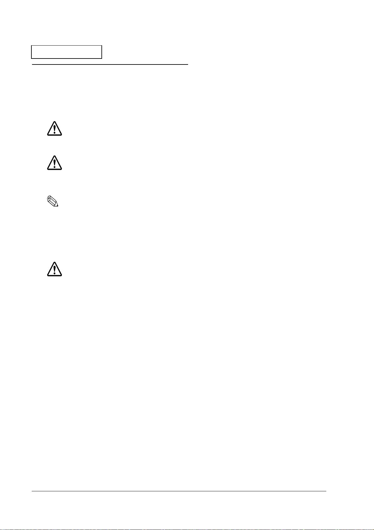
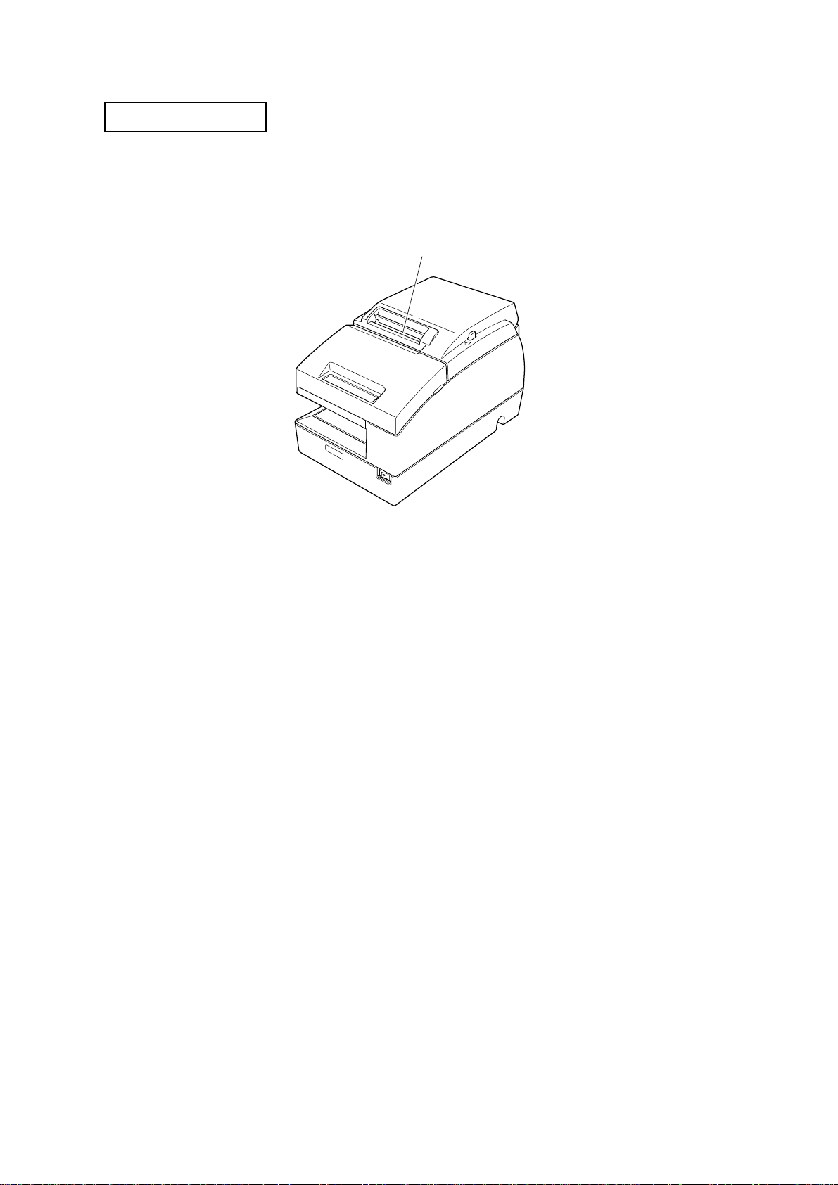
Opening and Closing the Platen
The printer opens and closes the platen once. Check this operation with the front cover opened.
check for the platen open and
close operation
Figure 1-1 Opening and closing the platen
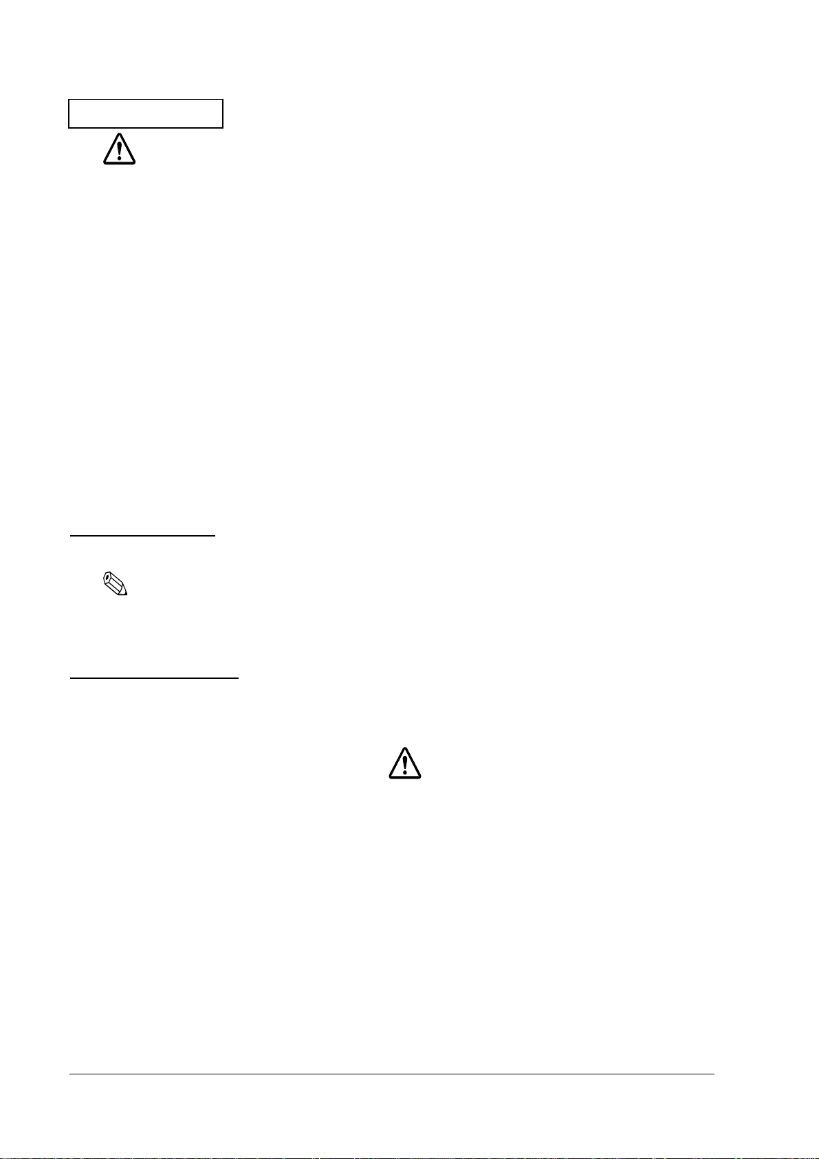
Detecting the Head Carriage Home Position
The head carriage on a dot impact printer moves to the left side (home position) once and then
to the right side before stopping. Check this operation with the front cover opened.
check for head carriage
movement
Figure 1-2 Detecting the head carriage home position
1-4 Troubleshooting Rev. A
Page 16
Confidential
TM-U675/U675P (with autocutter) Service Manual
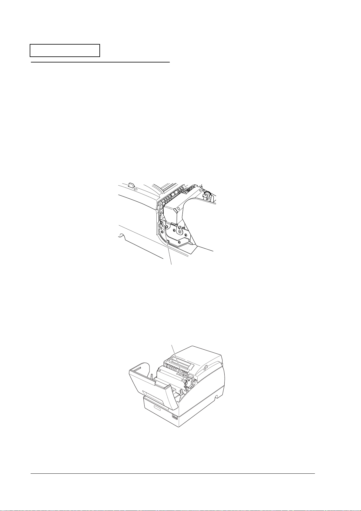
Feeding Roll Paper
Roll paper is fed 1 to 2 mm. You cannot see this if the roll paper is not inserted.
check for paper feed
Figure 1-3 Feeding roll paper
Rev. A Troubleshooting 1-5
Page 17

Confidential
Starting and Stopping Self Tests
Printing Tests
Starting the Tests
❏ Roll paper self test:
The printer starts printing on the roll paper when you turn on the power while holding
down the receipt FEED button when all the covers are closed.
operate the autocutter to cut the receipt.
❏ Slip paper self test:
The SLIP LED flashes and the printer enters the slip paper wait mode when you turn on the
power while holding down the RELEASE button when all the covers are closed. Printing
starts on the slip paper when you insert a slip of paper in the printer.
❏ Validation paper self test:
Turn on the power supply while holding down the FEED and the RELEASE buttons while
the cover is closed. The SLIP LED flashes and the printer enters the validation paper wait
status. In this state, printing begins on the validation paper when you insert validation
paper.
After printing is completed,
Test Wait Mode
❏ Roll paper self test:
After the test print is completed, the printer enters the self test wait mode. The PAPER OUT
LED flashes after printing "SELF-TEST printing. Please press PAPER FEED button."
Test printing starts when you press the receipt paper FEED button.
❏ Slip paper self test:
When the printer status print is completed, the printer ejects the slip and waits for the next
slip of paper. Test printing starts when you insert a slip of paper in the printer.
❏ Validation paper self test:
When the printer has ejected the validation paper, you can insert the next validation sheet
and printing continues.
Ending the Test
The printer prints "***completed***" and the test ends when the determined number of lines
have been printed. The printer enters the normal mode after the power on tests are
completed.
After printing to the paper roll, operate the autocutter to cut the receipt
.
1-6 Troubleshooting Rev. A
Page 18
Confidential
TM-U675/U675P (with autocutter) Service Manual
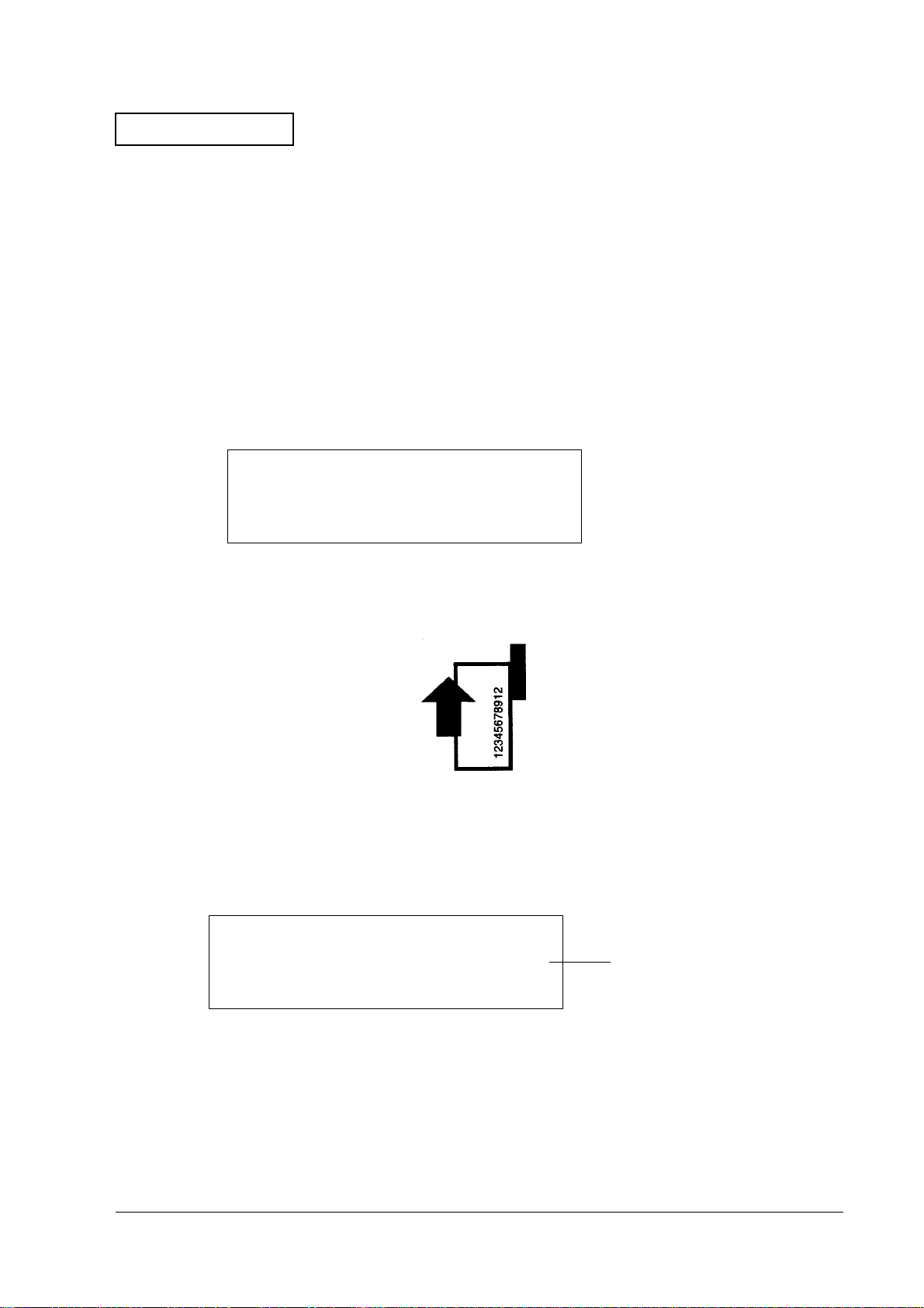
MICR Reader Test (Only with Printers that Have a MICR Unit)
1. Load the roll paper in the printer.
2. Turn off the power supply to the printer.
3. Open the roll paper cover.
4. Press the RELEASE button while turning on the power supply.
5. Press the RELEASE button seven times.
6. Close the roll paper cover.
7. The following message is printed on the roll paper. The SLIP LED flashes.
**** RECOGNITION MODE ****
Please set check.
8. Insert check paper into the printer. Insert so that the MICR characters are facing upward on
one side of the paper insertion slot. The printer will run a test to read the check.
9. After reading is completed, remove the check. The printer prints the check data on the roll
paper.
<Example Printing> With E13B Font Check Paper
??????????? ?? ?? ?? ?? ????? ????
T012345678T 90 12 34 56 78900 1234
Data that was read
(lower line).
Rev. A Troubleshooting 1-7
Page 19

Confidential
<Example Printing> With CMC7 Font Check Paper
=0000066 =123456789012^ 210987654321/
???????? ?????????????? ?????????????
10. Verify that the check was read correctly. You can continue running the test by inserting
more checks.
11. When you have finished the test, turn off the power supply to the printer.
Data that was read
(lower line).
1-8 Troubleshooting Rev. A
Page 20
Confidential
TM-U675/U675P (with autocutter) Service Manual
Troubleshooting Using the ERROR LED
You can learn the cause of a failure by checking the ERROR LED code. The following table
shows problems and solutions to repair the printer. Numbers in the "Solutions" column indicate
the order to use to check the problem. If you cannot determine the cause of the problem after
checking all the solutions listed, go back to the flowchart given earlier in this chapter.
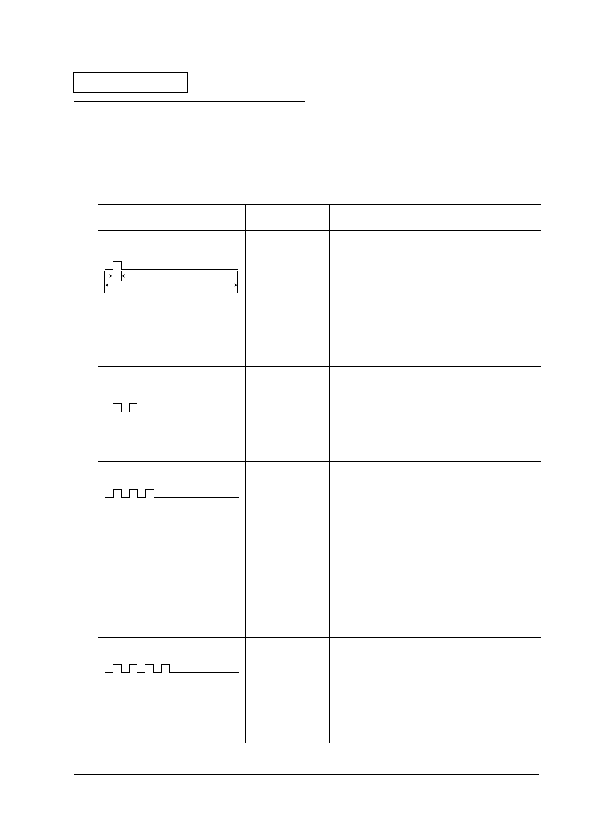
Table1-2 Error causes and solutions
Type of Error and ERROR LED Pattern Explanation
Autocutter Error An autocutter error
LED ON
320ms
5120ms
Carriage home position detection
error
was detected.
The head carriage
home position was
not correctly
detected.
Solutions
(Listed in the order you should use to check printer)
1. Check for paper jams around the autocutter. (See
page 1-19.)
2. Check the cutter motor assembly. (See page 1-11.)
If there has been a short in the cutter motor
assembly, replace the main circuit board unit at
the same time. (See page 2-96.)
3. Replace the main circuit board unit and see if the
problem is fixed. (See page 2-96.)
If the printer is repaired, refer to Test Points on the
Main Circuit Board Unit (See page 1-12.) to analyze
the defective areas on the board.
1. Check the carriage assembly for a paper jam.
(To remove the carriage cover, see page 1-16.)
2. Check for paper dust on the H.P. detector
assembly. (To remove the carriage cover, see
page 1-16.)
Carriage out-of-step error There is no carriage
detector output
even when the
carriage is
instructed to move.
Slip eject error The slip paper was
not ejected
normally.
3. Replace the H.P. detector assembly. (See page 2-
22.)
1. Check the carriage assembly for a paper jam.
(To remove the carriage cover, see page 1-16.)
2. Check the rotary encoder on the carriage motor
gear used to detect carriage position (The rotary
encoder is on the intermediate circuit board
assembly. You need to disassemble the
intermediate circuit board assembly to check the
encoder. To remove the intermediate circuit
board assembly, see page 2-22.)
3. Check the carriage motor. (See page 1-11.)
If the motor is shorted, replace it along with the
main board.
4. Replace the main circuit board unit and see if the
problem is fixed. (See page 2-96)
1. Look into the printer from the left side to check for
a paper jam in the slip paper transport path.
2. Check the paper feed motor. (See page 1-11)
If the motor is shorted, replace it along with the
main board.
3. Try installing a new main circuit board unit to see if
the printer is fixed. (See page 2-96)
Rev. A Troubleshooting 1-9
Page 21
Confidential
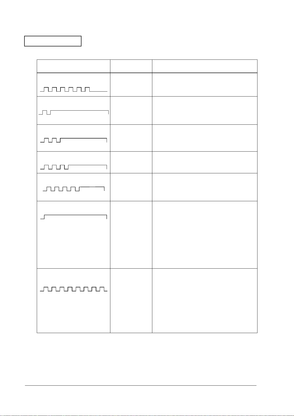
Table1-2 Error causes and solutions
Type of Error and ERROR LED Pattern Explanation
Roll paper cover open error The roll paper cover
(rear cover) was
detected as open
when printing.
Solutions
(Listed in the order you should use to check printer)
Close the roll paper cover (rear cover).
Memory or gate array R/W error The R/W check did
not operate
properly for the
memory or the
gate array.
High voltage error The power supply
voltage is high.
Low voltage error The power supply
voltage is low
CPU execution error An abnormal CPU
Drive circuit error One of the
operation was
detected, or the I/F
board is
disconnected.
following was
detected.
❏
Print head
thermistor
detection error
❏
Lever drive motor
assembly error
Replace the main circuit board unit to see if the
printer is repaired. (See page 2-96.)
Replace the power supply unit to see if the printer is
repaired. (See page C-4.)
Replace the power supply unit to see if the printer is
repaired. (See page C-4.)
1. Check whether the I/F board is connected.
2. Replace the main circuit board unit to see if the
printer is repaired. (See page 2-96.)
1. Check if the printer is repaired after replacing the
print head unit. (See page 1-15.)
2. Check the resistance of the lever drive motor
assembly. (See page 1-11.) Replace if shorted.
3. Check if the printer is repaired after replacing the
lever motor T. P. detector assembly. (See page 2-
78.)
4. Check if the printer is repaired after replacing the
main circuit board unit. (See page 2-96.)
Head high temperature error/roll
paper error
One of the
following problems
has occurred.
❏
The roll paper
has been
inserted into the
path wrong.
❏
The print head
temperature is
high.
1. If the error has occurred after loading the roll
paper, the roll paper has been inserted into the
path wrong. Reinstall the roll paper.
2. If the error occurred during printing, a high head
temperature has been detected. This error may
occur if you print continuously for too long. Leave
the printer as it is. The error will be automatically
cleared when the temperature has decreased. If
this error occurs frequently, check if the ambient
temperature is within specifications.
1-10 Troubleshooting Rev. A
Page 22
Confidential
TM-U675/U675P (with autocutter) Service Manual
Test Points on the Printer Mechanism
This section shows how to test the motor and the coils.
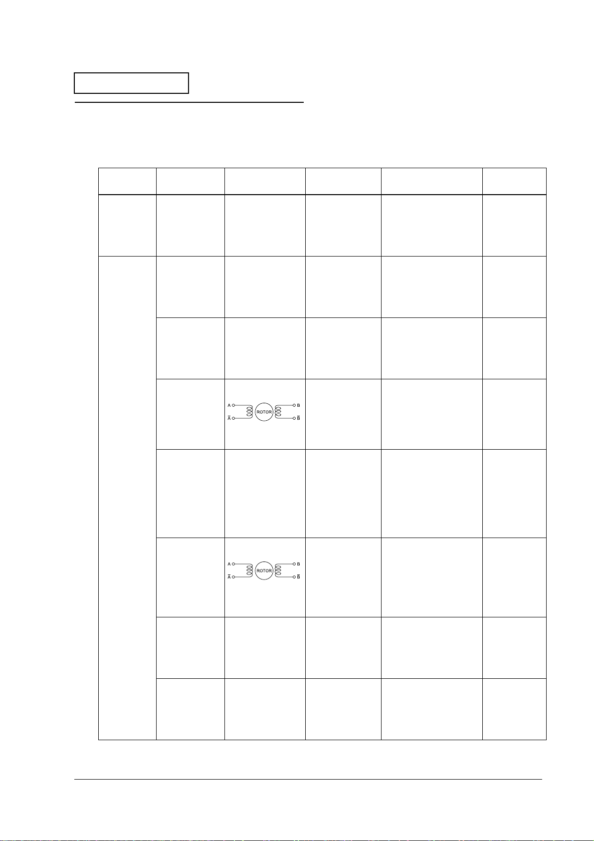
Table1-3 Test points on the printer mechanism
Name of
Mechanism Part Name Internal Element Function Where to Check Normal Status
Autocutter
unit
Mechanism
assembly
(M-U675)
Cutter motor
assembly
Lever drive coil
A (left side
when facing
the front of the
printer)
Lever drive coil
B (right side
when facing
the front of the
printer)
Carriage motor 4 phase stepping
Lever drive
motor assembly
Paper feed
motor
J/S change
solenoid
MICR solenoid Coil MICR hold drive Remove the cable
DC brush motor Autocutter drive Remove the cable
Coil • Form stopper
Coil • Platen open
motor
DC brush motor • Form stopper
4 phase stepping
motor
Coil Change of
operation
• Slip paper roller
(sub) operation
and close.
• Cylindrical
printer platen
open and close
Head carriage
drive
operation
• Slip paper roller
(sub) operation
• Platen open
and close
• Endorsement
printer platen
open and close
Slip paper feed Remove the cable
journal paper
drive/slip paper
drive.
connector connected
to CN7 on the main
circuit board unit and
test between pin 1 and
pin 2.
Remove the cable
connector connected
to CN30 on the main
circuit board unit and
test between pin 26
and pin 27.
Remove the cable
connector connected
to CN30 on the main
circuit board unit and
test between pin 26
and pin 28.
Remove the cable
connector connected
to CN30 on the main
circuit board unit and
test between pin 1 and
pin 2 and between
pin 3 and pin 4.
Remove the cable
connector connected
to CN30 on the main
circuit board unit and
test between pin 29
and pin 30.
connector connected
to CN30 on the main
circuit board unit and
test between pin 17
and pin 18 and
between
pin 19 and pin 20.
Remove the cable
connector connected
to CN30 on the main
circuit board unit and
test between pin 21
and pin 22 .
connector connected
to CN27 on the main
circuit board unit and
test between pin 1 and
pin 2 .
The line must
be continuous.
Approx. 70 Ω
Approx. 70 Ω
Approx. 4.5 Ω
(per 1 phase)
The line must
be continuous.
Approx. 8 Ω
(per 1 phase)
Approx. 45 Ω
Approx. 28.8 Ω
Rev. A Troubleshooting 1-11
Page 23

Confidential
Test Points on the Main Circuit Board Unit
After a main circuit board unit failure, one basic method for diagnosing the cause of the problem
on the main circuit board unit is to check the power supply line. Use the following table to check
the power supply line. First, check step number 1, and proceed to the next step if that is not the
problem.
Table1-4 Checking the power supply line
Step
# Type of Voltage
1 Voltage input
from the power
supply
2 Voltage input
from the power
supply
Location of
Measurement
CN29, pin 1 Output when
U11, pin 1 Output when
Condition of
Measurement
the power
supply is ON.
the power
supply is ON.
Normal
Value Presumed Cause of the Error
24 V ± 10 % It is possible that the problem is pre-
arcing of the F1 fuse. The fuse may
have pre-arced because of an
unusual input circuit.
Always replace the fuse after
removing the cause of the pre-arcing.
If you do not remove the cause of the
pre-arcing, and replace this fuse, the
problem may expand to
misoperation. Also, always use the
specified type of fuse when replacing.
24 V ± 10 % It is possible that the problem is pre-
arcing of the R3 fuse. The fuse may
have pre-arced because of a
problem in the logic power supply
circuit or because of a VCC overvoltage.
3 Logic voltage
(VCC)
4 Logic voltage
(VCC-PWR)
5 Logic voltage
(VCC-PWR2)
6 Logic voltage
(VCC_SEN)
VCC pad
(near L2)
VCC-PWR pad
(near U14,
pin 40)
U19, pin 8
potential
CN30, pin 5
potential
Output when
the power
supply is ON.
Output when
Q51 (C) is "0."
(24V SW1="H")
Output when
Q60 (C) is "0."
(24V SW2="H")
Output only
when there is
output sensor
conductivity
when CPU
output port
(SEN_PWR) is "L."
If pre-arcing of the R3 fuse happens,
do not repair the main circuit board
unit. The quality of several parts on the
circuit board is weakened by prearcing of the R3 fuse and safe
operation cannot be guaranteed.
5 V ± 5 % It is possible that the logic power
supply circuit has malfunctioned.
If you find this line has a problem, do
not repair the main circuit board unit.
The quality of several parts on the
circuit board is weakened, and safe
operation cannot be guaranteed.
5 V ± 5 % The logic power supply circuit or Q44
could have malfunctioned.
5 V ± 5 % The logic power supply circuit or Q59
could have malfunctioned.
5 V ± 5 % The logic power supply circuit or Q44
could have malfunctioned.
1-12 Troubleshooting Rev. A
Page 24

Confidential
Table1-4 Checking the power supply line
Step
# Type of Voltage
7 Mechanism
voltage
(24 VA)
8 Mechanism
voltage
(24 VB)
9 Mechanism
voltage
(24C)
Location of
Measurement
Located near
Q17 drain
Located near
Q7 Source
Located near
Q29 base
TM-U675/U675P (with autocutter) Service Manual
Condition of
Measurement
Output when
Q24 (C) is "0."
(24V SW2 = "H")
Only output
continuously
when power
supply unit is
connected.
Output when
Q46 (C) is "0."
(24V SW1="H")
Normal
Value Presumed Cause of the Error
24 V ± 10 % Q17 could have malfunctioned.
24 V ± 10 % Q61 could have malfunctioned.
24 V ± 10 % It is possible that the problem is pre-
arcing of the F2 fuse. The fuse may
have pre-arced because of a defect
in the 24V line circuit elements.
If pre-arcing of the F2 fuse happens,
do not repair the main circuit board
unit. The quality of several parts on the
circuit board is weakened by prearcing of the F2 fuse, and safe
operation cannot be guaranteed.
Rev. A Troubleshooting 1-13
Page 25
Confidential
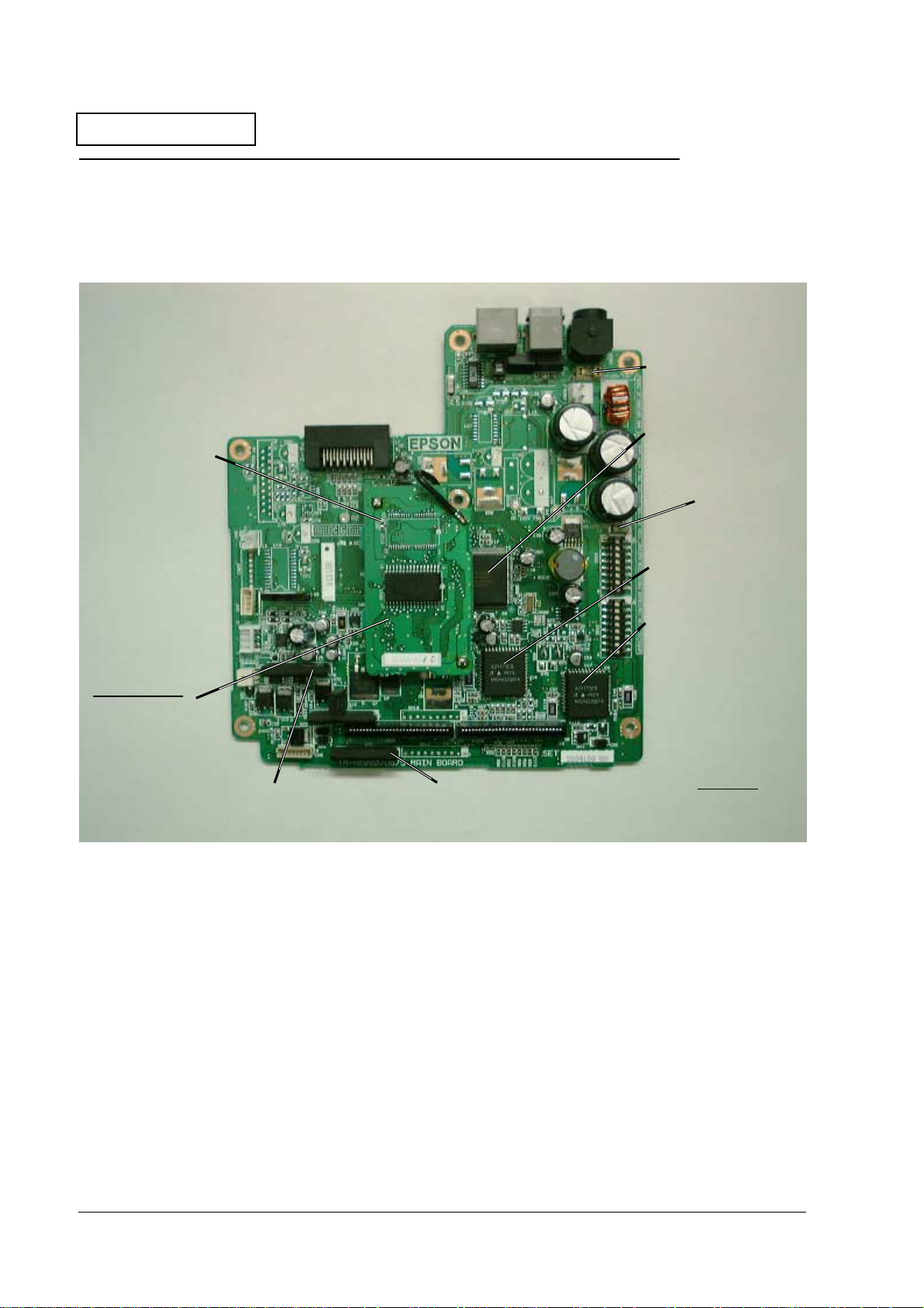
Locations of the Main Elements on the Main Circuit Board Unit
The following shows the locations of the main elements on the main circuit board unit.
Fuse (F1)
CPU (U3)
Gate array (U30)
*under the
memory board
Carriage motor
controller (U14)
Fuse (F2)
Memory board
Font ROM (U513)
Program ROM (U508)
SRAM (U509)
Figure 1-4 Locations of the main elements on the main circuit board unit
Impact dot head
drivers (QM8)
Impact dot head
drivers (QM6)
Slip paper feed motor
controller (U17)
*Rear side
Fuse (F4)
Fuse (R3)
1-14 Troubleshooting Rev. A
Page 26
Confidential
TM-U675/U675P (with autocutter) Service Manual
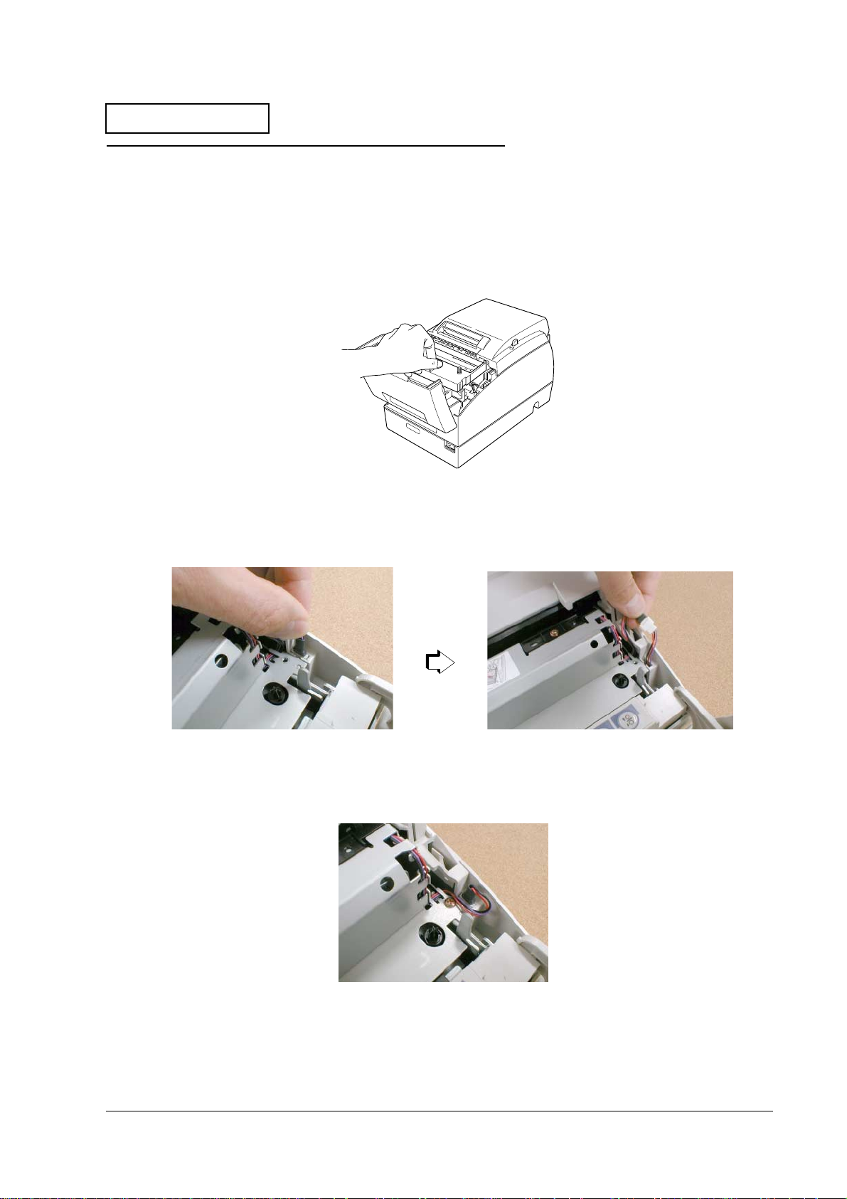
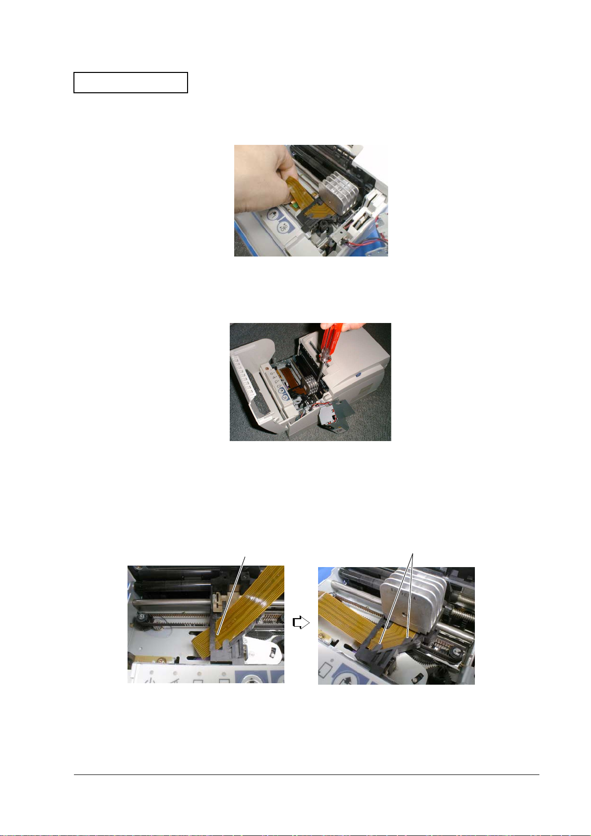
Procedures for Replacing the Print Head Unit
1. Turn off the power switch to the printer. Remove the power supply unit from the printer.
2. Open the printer front cover and remove the ribbon cartridge.
Figure 1-5 Removing the ribbon cartridge
3. Pull the cable connector out of the slit in the case.
Figure 1-6 Pulling the cable connector out
When you are reattaching the cable, arrange the cable wires as shown below.
Figure 1-7 Arranging the cable wires
Rev. A Troubleshooting 1-15
Page 27
Confidential
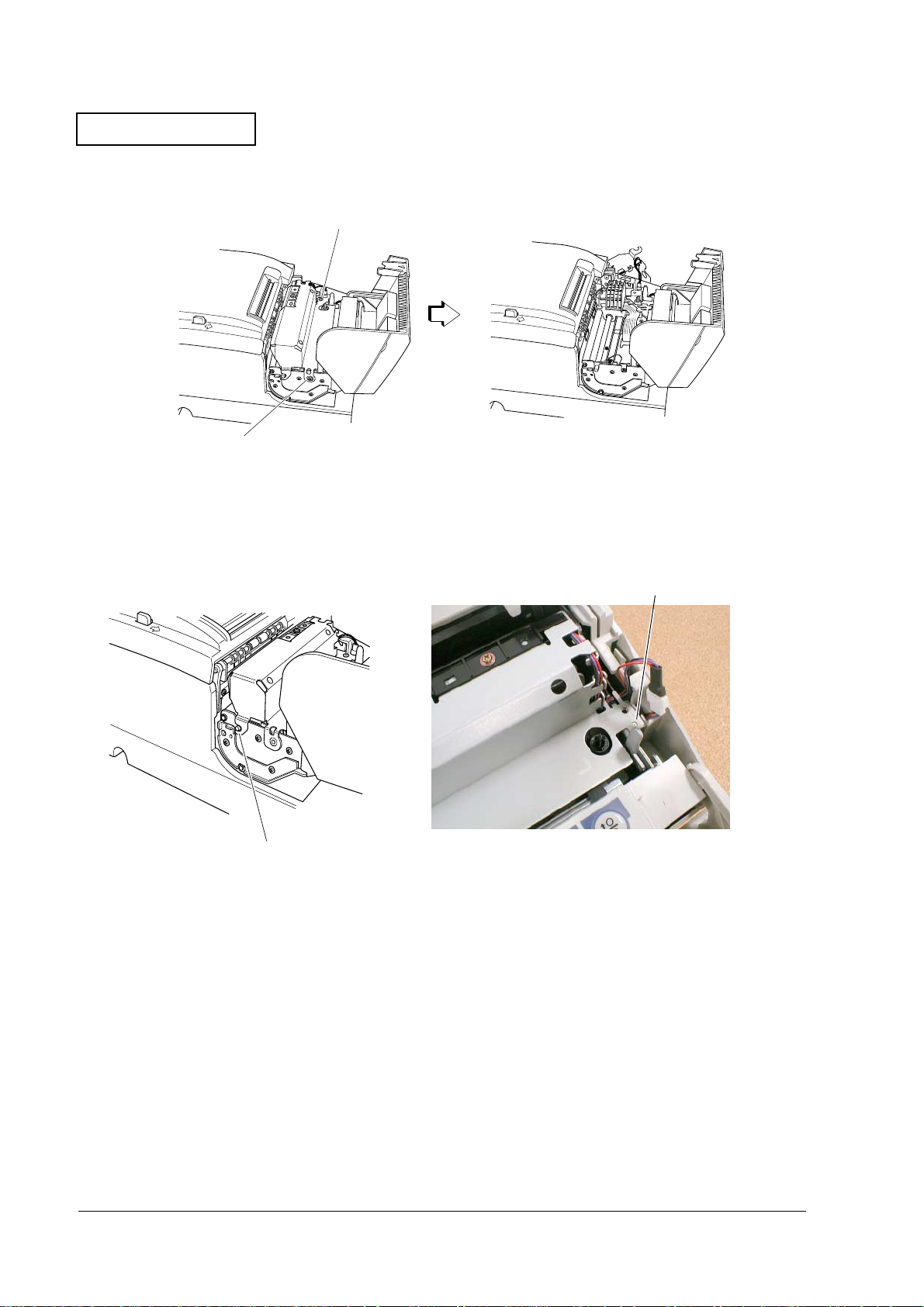
4. Remove the two screws and remove the carriage cover frame assembly.
screw
screw
Figure 1-8 Removing the carriage cover frame assembly
When you are reattaching the frame, insert the tooth on the left side into the shaft and align
the nib on the right side with the nib hole.
nib
tooth
Figure 1-9 Tooth and nib
1-16 Troubleshooting Rev. A
Page 28
Confidential
5. Move the head carriage to the right side and remove the print head unit flexible plastic cable
(FPC) from the connector.
Figure 1-10 Removing the print head unit FPC
6. Remove the screw and remove the print head unit.
TM-U675/U675P (with autocutter) Service Manual
Figure 1-11 Removing the print head unit
When attaching, pass the print head unit FPC through the slit in the head carriage and attach
below the two nibs.
two nibsslit
Figure 1-12 Slit and two nibs
Rev. A Troubleshooting 1-17
Page 29
Confidential
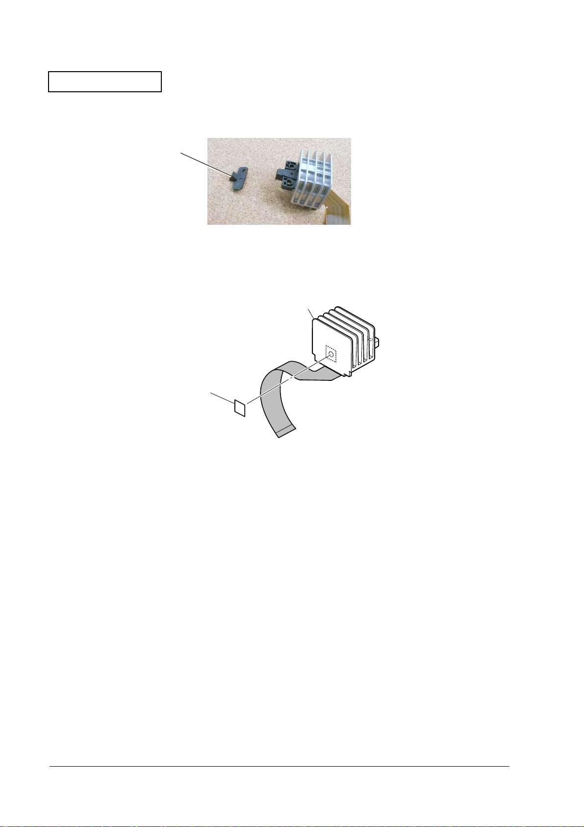
7. Remove the nose guide from the print head unit.
nose guide
Figure 1-13 Removing the nose guide
8. To reinstall the print head, reverse the procedures you used to remove it. When reinstalling,
affix the head seal to the print head unit.
print head unit
head seal
Figure 1-14
1-18 Troubleshooting Rev. A
Page 30
Confidential
TM-U675/U675P (with autocutter) Service Manual
Removing Paper Jams
Paper Jams in the Autocutter
Retract the autocutter movable blade using the following procedure.
1. Pull the latch levers on the right and left sides to the front and open the roll paper cover.
2. Rotate the knob on the autocutter in the direction of the arrow to align the axis with the
circular hole (marked with a triangular hole) in the center of the arc-shaped slit.
3. Remove the paper.
knob
marked arrow
Figure 1-15
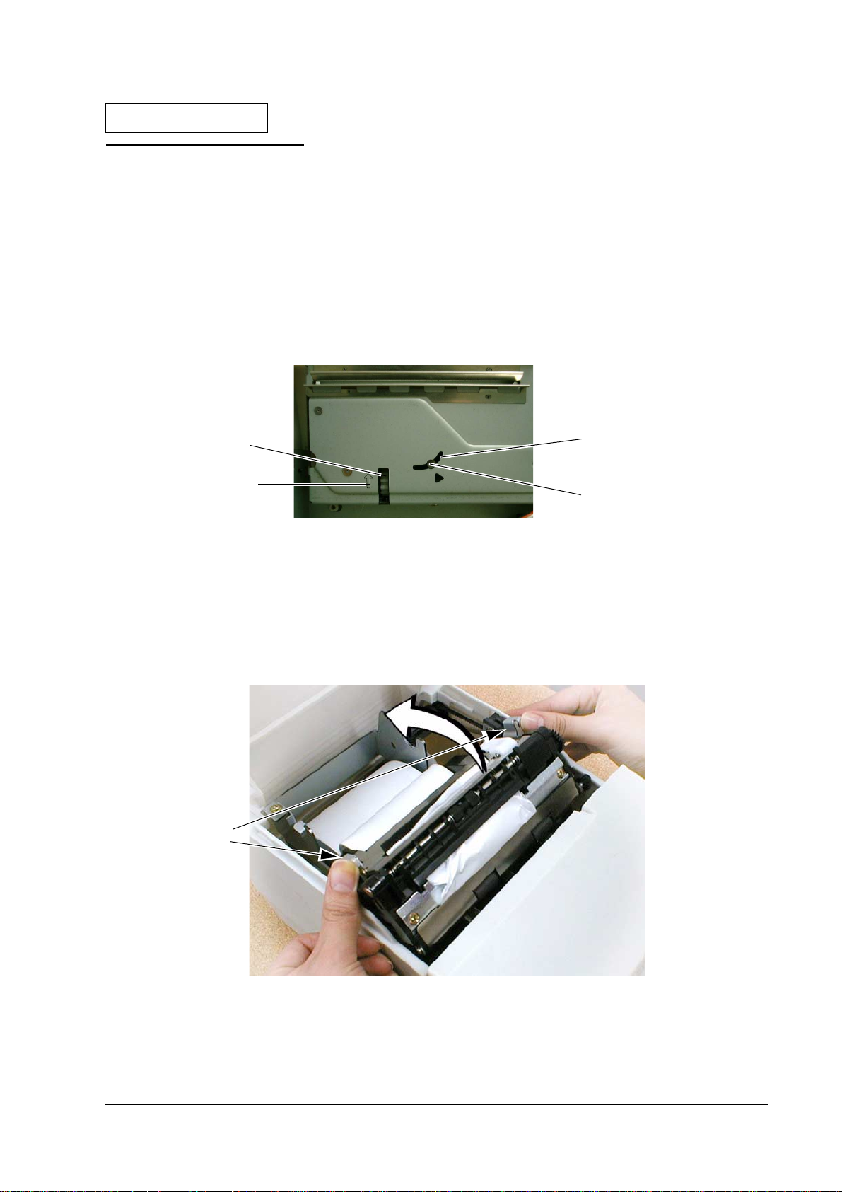
Paper Jams in the Roll Paper
1. Pull the latch lever to the front and open the roll paper cover.
2. Remove the take-up assembly.
3. Open the clamshell mechanism while pushing on the levers on both ends.
levers
arc-shaped slit
axis
Figure 1-16
Rev. A Troubleshooting 1-19
Page 31

Confidential
4. Remove the paper.
5. Close the clamshell mechanism. Push on the clamshell mechanism until you hear a clicking
sound.
6. Close the roll paper cover.
Paper Jams in the Slip Paper
1. Check that the power to the printer is turned ON. If it is not ON, turn it ON.
2. If the slip paper does not release, press the RELEASE button to free the slip paper.
3. Remove paper from the paper insertion side.
If you cannot remove the paper from the paper insertion side, or paper is cut partially while you
are removing it, follow the directions in the previous section entitled “Paper Jams in the Roll
Paper” to open the clamshell mechanism and remove the paper.
1-20 Troubleshooting Rev. A
Page 32

Confidential
TM-U675/U675P (with autocutter) Service Manual
Detector Functions and Positions
The following shows the positions and the functions of the detectors.
Table1-5 Detectors and functions
Mechanism Function
Home position detection
mechanism
Carriage detection mechanism Detection of head carriage malfunction
B.O.F. detection mechanism Slip detection
T.O.F. detection mechanism Slip detection
Paper ejection detection
mechanism
Roll paper end detection
mechanism
*Roll paper near-end
detection mechanism
Validation detector mechanism Validation paper detection
Lever motor T.P. detection
mechanism
Front cover detection mechanism Front cover open/closed status detection
Rear cover detection mechanism Detects the open/close status of the rear cover
Autocutter detector function Detects the position of the autocutter movable
Initial setting of printer (carriage home position)
Slip detection
Roll paper detection
Roll paper detection
Lever drive motor timing signal detection
blade.
*The roll paper near-end detector mechanism is installed in the paper supply unit.
Autocutter detector assembly
Rear cover detector assembly
Roll paper N.E. detector (micro switch)
Roll paper end detector assembly
Lever motor T.P. detector
assembly
Home position detector
assembly
Figure 1-17
Paper ejection detector assembly
Front cover detector assembly
Validation detector assembly
T.O.F. detector
assembly
Carriage detector
assembly
B.O.F. detector
assembly
Rev. A Troubleshooting 1-21
Page 33

Confidential
1-22 Troubleshooting Rev. A
Page 34

Confidential
TM-U675/U675P (with autocutter) Service Manual
Chapter 2
Assembly and Disassembly
Before Assembly and Disassembly
Always observe the following precautions when disassembling and assembling the printer.
CAUTION:
Always remove the power supply unit from the printer before working. Power is flowing
in the internal circuit board even if you turn the printer off with the power supply switch.
You can damage the printer if you work with the power supply still attached.
Remove all peripheral equipment connected to the printer before starting your work.
Do not perform any work that is not described in this chapter. Doing so can result in
injuries or damage to the printer.
Do not touch the FPC or the FFC pins with your hands.
About this Chapter
Procedures
This chapter provides the procedures for assembling. Reverse them to disassemble the printer.
Assembly is organized into “Assembling the Mechanism Assembly (M-U675),” and
“Assembling the TM-U675.” Each section is further divided into “Pre-assembly” and
“Assembly.”
Do “Pre-assembly” steps first, and then do “Assembly” after you have assembled the parts into
units to some degree.
Rev. A Assembly and Disassembly 2-1
Page 35

Confidential
Assembling the Mechanism Assembly (M-U675)
Pre-assembly Procedures
Pre-assembly of the Validation Detector Assembly
1. Solder lead wires S, T, R to the validation circuit board.
697 Validation detector assembly
757 Lead wire (type R)
758 Lead wire (type S)
759 Lead wire (type T)
Figure 2-1
2-2 Assembly and Disassembly Rev. A
Page 36

Confidential
TM-U675/U675P (with autocutter) Service Manual
Pre-assembly of the Slip B.O.F. Detector Assembly
1. Solder lead wires C, D, E to the slip B. O. F. detector assembly.
2. Insert the slip B. O. F. detector assembly into the slip insertion detector holder.
606 Slip insertion detector holder
696 Slip B.O.F. detector assembly
742 Lead wire (type C)
743 Lead wire (type D)
744 Lead wire (type E)
Figure 2-2
Rev. A Assembly and Disassembly 2-3
Page 37

Confidential
Pre-assembly of the Lever Drive Coil Assembly
1. Attach lever drive coils (type A, B) to the lever coil mounting plate sub assembly. The rack
for lever drive coil (type A, B) should face upward. Do not confuse type A and B. Type A
uses brown lead wires. Type B uses gray lead wires.
2. Assemble the paper feed trigger attraction plates to the lever drive coils (type A, B).
3. Hook paper feed trigger claw springs onto the lever coil mounting plate sub assembly and
paper feed trigger attraction plate. One side of the hook on the paper feed trigger claw
spring is single and the other side is double. Attach the double side onto the paper feed
trigger attraction plate.
4. Lubricate the areas where the paper feed trigger attraction plate contacts other parts (eight
places).
G-36
732
Paper feed trigger attraction plate
621
Lever drive coil (type A)
731
Paper feed trigger claw spring
G-36
731
Paper feed trigger claw spring
Figure 2-3
732
Paper feed trigger attraction plate
G-36
622
Lever drive coil (type B)
695
Lever coil mounting plate sub assembly
2-4 Assembly and Disassembly Rev. A
Page 38

Confidential
TM-U675/U675P (with autocutter) Service Manual
Pre-assembly of the Paper Feed Motor
Note:
Perform the following three steps only if your printer has a MICR unit.
1. Insert the paper feed motor into the motor shield case. Insert the paper feed motor gear into
the hole in the motor shield case. Check that the motor printed circuit board (PCB) fits into
the notch.
2. Insert two motor shield spacers into the motor shield case.
3. Attach the motor shield cover onto the motor shield case (two places). Align the screw holes
and the nibs on the opposite side, and push in so that they snap fit.
781 Motor shield cover
Screw (C.C.S-tite, 2.5X5)
725
779
Motor shield spacer
739
Paper feed motor
780
Motor shield case
726
Screw (C.B.S-tite F, 3X6)
Figure 2-4
Rev. A Assembly and Disassembly 2-5
Page 39

Confidential
Pre-assembly of the J/S Change Solenoid Assembly
1. Attach the J/S change solenoid to the J/S solenoid mounting plate. When doing so, tighten
the screw while the J/S change solenoid is touching the nib on the right side of the J/S
solenoid mounting plate.
2. Attach the J/S change lever to the J/S solenoid mounting plate, and hook the J/S change
spring.
3. Lubricate the sliding part of the J/S change solenoid mounting plate and the J/S change
lever in four places.
651
J/S change spring
716
Screw (C.C., 2X3)
774
J/S solenoid mounting plate
G-36
G-36
650 J/S change lever
727
J/S change solenoid
Figure 2-5
2-6 Assembly and Disassembly Rev. A
Page 40

Confidential
Pre-assembly of the Slip T. O. F. Detector Assembly
1. Solder lead wires I, J, K to the slip T. O. F. detector assembly.
703 Slip T.O.F. detector assembly
Figure 2-6
TM-U675/U675P (with autocutter) Service Manual
748 Lead wire (type I)
749 Lead wire (type J)
750 Lead wire (type K)
Rev. A Assembly and Disassembly 2-7
Page 41

Confidential
Pre-assembly of the Lever Motor T. P. Detector Assembly
1. Solder lead wires F, G, H to the lever motor T. P. detector assembly.
704 Lever motor T.P. detector assembly
745 Lead wire (type F)
746 Lead wire (type G)
747 Lead wire (type H)
Figure 2-7
2-8 Assembly and Disassembly Rev. A
Page 42

Confidential
TM-U675/U675P (with autocutter) Service Manual
Pre-assembly of the MICR Unit
Note:
Perform the following 16 steps only if your printer has a MICR unit.
1. Solder the MICR connector assembly lead wires to the MICR head.
2. Align the MICR frame and MICR head with the nib and attach with one screw.
782 MICR assembly
MICR connector assembly
786
Screw (C.P.(S-P2), 2.5X5)
793
792 MICR frame assembly
Figure 2-8
Rev. A Assembly and Disassembly 2-9
Page 43

Confidential
3. Attach the MICR fixing sheet to the MICR fixing. Set the hole on the MICR fixing sheet over
the MICR fixing nib and attach so that the MICR fixing sheet does not protrude from the
MICR fixing.
4. Attach the MICR fixing to the MICR lever. The tabs on the MICR fixing should fit into the
MICR grooves.
5. Assemble by inserting the MICR roller shaft. (Attach the shaft with one E-ring.)
787 MICR lever
778 E-ring (1.2)
777 MICR roller shaft
Hole
791 MICR fixing sheet
Nibs
Tabs
Looking directly from the bottom
Figure 2-9
788 MICR fixing
2-10 Assembly and Disassembly Rev. A
Page 44

Confidential
TM-U675/U675P (with autocutter) Service Manual
6. Insert the two MICR lever guide shafts into the MICR frame, starting with the end with the
smaller diameter.
7. Lubricate the areas where the MICR lever and the MICR frame are in contact (six places).
8. Attach the MICR frame to the MICR lever as shown in the drawing.
787 MICR lever
792 MICR frame assembly
796 MICR lever guide shaft
G-47
G-47
Figure 2-10
G-47
Rev. A Assembly and Disassembly 2-11
Page 45

Confidential
9. Fit the MICR solenoid into the MICR case.
10. Align and fit the MICR solenoid nib into the MICR frame assembly.
11. Position and attach the MICR lever fixing plate to the MICR lever nib. (Use two screws to
attach.)
Note:
Tighten the screws while holding the MICR solenoid. Check that the MICR lever will fall under its
own weight.
784 MICR lever fixing plate
794
Screw (C.P.(S), 2.6X8)
783 MICR case
789 MICR solenoid
Figure 2-11
2-12 Assembly and Disassembly Rev. A
Page 46

Confidential
TM-U675/U675P (with autocutter) Service Manual
12. Insert to attach the MICR roller shaft from the opposite direction of the MICR lever fixing
plate. Attach with one E-ring.
13. Attach the MICR lever spring on the hooks.
14. Check that opening and closing the MICR head assembly has a clicking feel to it.
15. Insert the MICR shield cover into the three slits in the MICR frame.
16. Hook the MICR connector assembly lead wire to the hook on the MICR frame.
785 MICR shield cover (type A)
778 E-ring (1.2)
MICR lever spring
790
777 MICR roller shaft
Figure 2-12
Rev. A Assembly and Disassembly 2-13
Page 47

Confidential
Pre-assembly of the Carriage Frame Unit
1. Lubricate the carriage motor shaft.
2. Insert the carriage drive pulley into the carriage motor shaft.
3. Lubricate the inside of the carriage drive pulley.
4. Attach the belt drive cap to the carriage drive pulley and secure it with one E-ring. Place the
belt drive cap with flat surface face up to install it.
720
E-ring (2)
603
Belt drive cap
633
Carriage drive pulley
G-36
G-36
Carriage motor
733
Figure 2-13
2-14 Assembly and Disassembly Rev. A
Page 48

Confidential
TM-U675/U675P (with autocutter) Service Manual
Pre-assembly of the Carriage Assembly
1. Insert the oil rings into the carriage assembly and lubricate. When doing so, insert the flat
surface of the oil rings so that they are facing up and down.
2. Hook the carriage spring to the carriage assembly. Push in until you feel the carriage spring
click.
709
Carriage assembly
605
Oil ring
611 Carriage spring
Rounded side
O-10
O-10
Figure 2-14
Rev. A Assembly and Disassembly 2-15
Page 49

Confidential
3. Insert the carriage belt into the carriage assembly. Fit the belt along the grooves in the
bottom side of the carriage assembly. For the direction of the belt, see the illustration below.
629
Carriage belt
709
Carriage assembly
Figure 2-15
2-16 Assembly and Disassembly Rev. A
Page 50

Confidential
Pre-assembly of the H. P. Detector Assembly
1. Solder lead wires L, M, N in that order to the H. P. detector assembly.
707 H.P. detector assembly
Figure 2-16
TM-U675/U675P (with autocutter) Service Manual
751 Lead wire (type L)
752 Lead wire (type M)
753 Lead wire (type N)
Rev. A Assembly and Disassembly 2-17
Page 51

Confidential
Pre-assembly of the Carriage Frame
1. Lubricate five shafts on the carriage frame sub assembly.
2. Insert the ribbon feed spring into the shaft shown in the figure below. Set the ribbon feed
spring claw upward and insert all the way by rotating the ribbon feed spring clockwise.
3. Lubricate the surface of the ribbon feed spring.
4. Attach the ribbon take-up gear assembly to the top of the ribbon feed spring. Align the
ribbon feed spring claw and the ribbon take-up gear assembly and insert.
5. Attach the carriage transmission pulley to the shaft shown in the figure below.
6. Apply lubrication to the hole in the carriage transmission pulley.
7. Attach the belt drive cap. Place the belt drive cap with the flat surface face up to install it.
712 Ribbon take-up gear assembly
G-36
Ribbon feed
601
spring
603 Belt drive cap
G-36
Carriage frame
sub assembly
632
Carriage transmission pulley
G-36
G-36
Figure 2-17
2-18 Assembly and Disassembly Rev. A
Page 52

Confidential
TM-U675/U675P (with autocutter) Service Manual
8. Insert the carriage drive transmission gear into the shaft shown in the figure below.
9. Insert the ribbon reduction gear into the shaft shown in the figure below.
10. Insert the ribbon intermediate gear into the shaft shown in the figure below. The smaller
diameter ribbon intermediate gear should be on the lower side.
11. Attach the ribbon drive plate assembly above the ribbon reduction gear and the ribbon
intermediate gear. Set the gear side of the ribbon drive plate assembly downward.
12. Attach the gear train cover to the carriage drive transmission gear.
13. Fasten the belt drive cap, carriage drive transmission gear, and ribbon drive plate assembly
with three E-rings.
720
E-ring (2)
Ribbon drive plate assembly
Ribbon reduction gear
Carriage frame sub assembly
720
E-ring (2)
706
682
768
Gear train cover
634 Carriage drive transmission gear
683 Ribbon intermediate gear
720 E-ring (2)
Figure 2-18
Rev. A Assembly and Disassembly 2-19
Page 53

Confidential
14. Insert the hole in the carriage motor onto the carriage frame sub assembly nib. Temporarily
fasten the screw on the lead wire side.
15. Loosen the screw you temporarily tightened in the previous step (less than one turn).
16. Hook the belt tension spring on the carriage motor and carriage frame sub assembly.
Carriage frame sub assembly
Nib
Carriage motor
733
775
Screw
(C.P.S-tite(P4), 3x6)
630 Belt tension spring
Figure 2-19
2-20 Assembly and Disassembly Rev. A
Page 54

Confidential
TM-U675/U675P (with autocutter) Service Manual
17. Attach the carriage assembly to the carriage frame sub assembly. When doing so, set the
carriage spring under the bent part on the carriage frame sub assembly as shown in the
illustration. Insert the carriage guide shaft and secure it with one E-ring.
18. Lubricate the right and left sides of the carriage guide shaft.
19. Hook the carriage belt onto the carriage drive pulley (shown with “1” in the illustration) and
carriage transmission pulley (shown with “2” in the illustration) in that order.
20. Tighten the screw (the screw loosened in step 15) on the lead wire side of the carriage motor.
21. Secure another screw to firmly tighten the carriage motor.
688
Carriage
frame sub
assembly
1
688
Carriage frame sub assembly
611 Carriage spring
709
Carriage assembly
723 E-ring (5)
O-10
775
Screw (C.P.S-tite(P4), 3x6)
Figure 2-20
2
631
Carriage guide shaft
O-10
Rev. A Assembly and Disassembly 2-21
Page 55

Confidential
22. Align the intermediate circuit board assembly to the carriage frame sub assembly with two
dowels, and attach the intermediate circuit board cover.
23. Tighten the intermediate circuit board assembly and intermediate circuit board cover
together with two screws.
24. Attach the H. P. detector assembly to the carriage frame sub assembly with one screw. Pass
the H. P. detector assembly lead wires to the bottom through the hole in the carriage frame
sub assembly.
775 Screw (C.P.S-tite(P4), 3x6)
707 H.P. detector assembly
688
Carriage
frame sub
assembly
769
Intermediate circuit board cover
775
Screw (C.P.S-tite(P4), 3x6)
708
Intermediate
circuit board assembly
775 Screw (C.P.S-tite(P4), 3x6)
Figure 2-21
2-22 Assembly and Disassembly Rev. A
Page 56

Confidential
TM-U675/U675P (with autocutter) Service Manual
25. Pass the flexible plastic cable (FPC) for the print head unit (Eb) through the slit in the
carriage assembly. When you do this, the FPC should be below the two hooks on the
carriage assembly. Install the print head unit (Eb) onto the carriage assembly. Connect the
FPC to the intermediate circuit board assembly connector.
26. Attach the nose guide on the print head unit (Eb) while aligning the three nibs. Secure the
nose guide with one screw.
27. Attach the head seal to the print head unit (Eb).
28. Lubricate the carriage motor gear and the top of the E-ring fastening the ribbon drive plate
assembly.
Slit
Hooks
FPC
795
Head seal
G-36
623
Nose guide
Print head unit (Eb)
FPC
689
608
Screw (C.P.P-tite, 3X12)
G-36
Figure 2-22
Print head unit (Eb)
689
FPC
688
Carriage frame sub assembly
709 Carriage assembly
708
Intermediate circuit board assembly
Figure 2-23
Rev. A Assembly and Disassembly 2-23
Page 57

Confidential
29. Solder four carriage motor cables and three H. P. detector assembly cables to the
intermediate circuit board assembly.
30. Solder intermediate cables A, B, C to the intermediate circuit board assembly.
31. Cover intermediate cables A, B, C with the intermediate cable tube. Fold the intermediate
cables A, B, C to the right side.
Four cables
for motor
carriage
Three cables
for H.P. detector
assembly
Intermediate cable tube
771
734 Intermediate cable (type A)
735 Intermediate cable (type B)
736 Intermediate cable (type C)
708 Intermediate circuit board assembly
Figure 2-24
2-24 Assembly and Disassembly Rev. A
Page 58

Confidential
Pre-assembly of the Front Cover Detector Assembly
1. Solder lead wires V, U, W in that order to the front cover detector assembly.
691 Front cover detector assembly
760 Lead wire (type U)
761 Lead wire (type V)
762 Lead wire (type W)
Figure 2-25
TM-U675/U675P (with autocutter) Service Manual
Rev. A Assembly and Disassembly 2-25
Page 59

Confidential
Pre-assembly of the Rear Cover Detector Assembly
1. Solder lead wires X, Y, Z to the cover detector circuit board.
692 Rear cover detector assembly
763 Lead wire (type X)
764 Lead wire (type Y)
765 Lead wire (type Z)
Figure 2-26
2-26 Assembly and Disassembly Rev. A
Page 60

Confidential
Pre-assembly of the Paper End Detector Assembly
1. Solder lead wires O, P, Q to the paper end detector circuit board.
754 Lead wire (type O)
755 Lead wire (type P)
756 Lead wire (type Q)
Figure 2-27
TM-U675/U675P (with autocutter) Service Manual
710 Paper end detector assembly
Rev. A Assembly and Disassembly 2-27
Page 61

Confidential
Pre-assembly of the Assist Paper Guide Assembly
1. Attach the backup paper guide cap to the center of the assist paper guide.
2. Attach the paper hold roller and assist paper guide spring to the assist paper guide. When
doing so, attach the assist paper guide spring in the direction shown in the figure.
3. Pass the paper hold roller shaft through the assist paper guide and fasten C-rings in 2 places.
4. Lubricate the center of the hole in the paper hold roller.
678 Backup paper guide cap
664 Assist paper guide
C-ring (5103-21)
772
Paper hold roller
665
G-36
642 Paper hold roller shaft
653 Assist paper guide spring
772 C-ring (5103-21)
Figure 2-28
2-28 Assembly and Disassembly Rev. A
Page 62

Confidential
TM-U675/U675P (with autocutter) Service Manual
Paper feed frame assembly
1. Insert the paper guide lever and the sub paper hold roller into the paper feed frame
assembly.
2. Pass the sub paper hold roller shaft into the paper feed frame assembly and sub paper hold
roller. (E-ring, 1 place)
3. Attach the paper guide lever spring and paper ejection detector holder to the paper guide
lever with one E-ring. Attach the paper guide lever spring in the direction shown in the
figure.
698 Paper feed frame assembly
724
E-ring (2.3)
640
663
Sub paper
hold roller
639
Paper guide lever shaft
Sub paper hold roller shaft
724
E-ring (2.3)
658 Paper guide lever
652 Paper guide lever spring
Figure 2-29
Rev. A Assembly and Disassembly 2-29
Page 63

Confidential
4. Attach the sub paper feed roller assembly and the crank shaft holders to the paper feed
frame assembly.
5. Lubricate the areas where the sub paper feed roller assembly and the crank shaft holder are
in contact.
6. Attach the parallel pin and paper feed gear to the sub paper feed shaft with two E-rings.
722
E-ring (4)
G-48
730
Crank shaft
holder
699 Sub paper feed roller assembly
G-48
602 Parallel pin (1.6X10)
730 Crank shaft holder
648 Paper feed gear
722 E-ring (4)
Sub paper feed roller assembly
699
Figure 2-30
602
2-30 Assembly and Disassembly Rev. A
Page 64

Confidential
7. Hook the paper guide lever spring to the paper guide lever and paper feed frame. Insert the
tip of the short side of the spring into the lever groove, and bend the spring to hook the tip of
the long side on the inside in the gap in the frame.
698 Paper feed frame assembly
TM-U675/U675P (with autocutter) Service Manual
652
Paper guide lever spring
Figure 2-31
658 Paper guide lever
Rev. A Assembly and Disassembly 2-31
Page 65

Confidential
8. Snap-fit the paper feed frame assembly to the paper end detector to attach.
710 Paper end detector assembly
Figure 2-32
2-32 Assembly and Disassembly Rev. A
Page 66

Confidential
TM-U675/U675P (with autocutter) Service Manual
9. Attach the paper feed roller to the paper feed frame assembly.
10. Attach the crank shaft holder, parallel pin, and the paper feed gear to the paper feed roller
with two E-rings.
11. Lubricate the sliding parts of the paper feed roller and crank shaft holder.
12. Attach the paper feed gear to the axis shown in the figure for the paper feed frame assembly
with one E-ring.
G-48
722 E-ring (4)
730 Crank shaft holder
648 Paper feed gear
722 E-ring (4)
G-48
666
Paper feed roller
Crank shaft holder
Figure 2-33
602
730
648 Paper feed gear
722 E-ring (4)
602 Parallel pin (1.6X10)
666
Paper feed roller
Rev. A Assembly and Disassembly 2-33
Page 67

Confidential
13. Attach the assist paper guide to the paper feed frame assembly using the paper feed roller
springs.
14. Set the hooks for the paper feed roller springs into the grooves for the shaft and hang the
loop of the spring onto the protrusion on the paper feed frame assembly. Be careful of the
direction of the attachment of the spring.
654
Paper feed roller spring
654
Paper feed roller spring
Figure 2-34
2-34 Assembly and Disassembly Rev. A
Page 68

Confidential
TM-U675/U675P (with autocutter) Service Manual
15. Insert the slip feed roller holder into the slip feed roller.
16. Attach the slip feed roller to the platen lever assembly with one E-ring. Insert the pinshaped nib of the slip feed roller holder into the third hole from the left on the platen lever
assembly.
17. Push the slip drive gear into the slip feed roller from the side with the larger diameter.
18. Apply lubrication to both sides of the slip feed roller and the slip feed roller holder. Rotate
the roller several times to allow the oil to work its way completely around.
72 E-ring (3)
624 Platen lever assembly
G-48
Slip feed roller holder
659
668
G-48
668
Slip feed roller
Figure 2-35
649 Slip drive gear
Rev. A Assembly and Disassembly 2-35
Page 69

Confidential
19. Insert the nylon lock nut (M3) onto the platen lever assembly on the side where the platen
ground plate (type A) is to be attached. The rounded side of the nylon lock nut (M3) should
be facing the direction shown in the illustration.
20. Insert the platen ground plate (type A) into the platen lever assembly.
21. Insert the two platen springs into the platen lever assembly.
22. Insert another nylon lock nut (M3).
23. Attach the platen assembly to the platen lever assembly. Secure the two platen adjustment
screws.
24. Attach the slip paper guide to the platen lever assembly. Hang the slip paper guide on the
hooks in three places on the platen lever assembly and fit the 2 nibs.
Platen adjustment screw
685
Nylon lock nut
Platen spring
718
604
711 Platen assembly
670
Slip paper guide
Figure 2-36
685 Platen
adjustment screw
604
Platen spring
718 Nylon lock nut
674
Platen ground
plate (type A)
2-36 Assembly and Disassembly Rev. A
Page 70

Confidential
TM-U675/U675P (with autocutter) Service Manual
25. Attach the platen lever assembly, platen ground plate B, and the platen lever spring to the
paper feed frame assembly. Insert the platen lever spring onto the cross-shaped protrusion
on the paper feed frame, and insert the other end onto the protrusion on the platen lever
assembly.
26. Insert the left and right platen lever shafts into the holes in the platen lever assembly and
attach with two E-rings.
721 E-ring (3)
721 E-ring (3)
Left platen lever shaft
626
Figure 2-37
727
J/S change solenoid
625
Platen lever spring
675
Platen ground plate
(type B)
Rev. A Assembly and Disassembly 2-37
Page 71

Confidential
27. Insert the lead wires for the paper end detector assembly in their specified positions.
Figure 2-38
2-38 Assembly and Disassembly Rev. A
Page 72

Confidential
TM-U675/U675P (with autocutter) Service Manual
28. Attach the cover ground plate to the paper feed frame assembly.
29. Cover the paper feed frame assembly using the paper feed cover and tighten the two plate
assembly lever screws.
30. Hang the assist paper guide spring onto the paper feed frame cover. Check the operation of
the assist paper guide.
31. Insert the paper release lever into the platen lever assembly and attach to the release lever
shaft with one E-ring.
32. Attach the guide roller shaft and sub paper hold roller to the paper feed frame assembly
with two E-rings.
719
609
Screw (C.B.P-tite, 3X6)
676
Cover ground plate
669
Paper feed frame cover
E-ring (1.5)
657 Paper release lever
638 Release lever shaft
609
Screw (C.B.P-tite, 3X6)
720
E-ring (2)
663 Sub paper hold roller
Figure 2-39
641 Guide roller shaft
663
Sub paper hold roller
720
E-ring (2)
Rev. A Assembly and Disassembly 2-39
Page 73

Confidential
33. With one E-ring, attach the paper feed frame fixing L lever assembly and the paper feed
frame fixing lever spring to the paper feed release assembly. Hang the spring onto the paper
feed frame fixing L lever assembly and hang onto the protrusion on the paper feed frame so
that it passes below the cover ground plate.
34. With one E-ring, attach the paper feed frame fixing R lever assembly and the paper feed
frame fixing lever spring to the paper feed release assembly. Hang the spring onto the paper
feed frame fixing R lever assembly and hang the spring onto the protrusion of the paper feed
frame assembly.
701
Paper feed frame fixing L lever
assembly
722
E-ring (4)
Paper feed frame fixing
655
lever spring
Figure 2-40
702
Paper feed
frame fixing R
lever assembly
655
Paper feed
frame fixing
lever spring
722
E-ring (4)
2-40 Assembly and Disassembly Rev. A
Page 74

Confidential
TM-U675/U675P (with autocutter) Service Manual
35. Attach the parallel pin and paper feed gear to the paper feed roller with one E-ring.
602
648 Paper feed gear
722 E-ring (4)
602
Parallel pin (1.6X10)
Figure 2-41
Rev. A Assembly and Disassembly 2-41
Page 75

Confidential
Pre-assembly of the Carriage Cover Frame Assembly
1. Solder the paper ejection detector cable assembly (type B) to the paper ejection detector
assembly. After soldering, pass the cables through the slit in the paper ejection detector
assembly.
690
Paper ejection detector assembly
Slit
738
Paper ejection detector cable (type B) assembly
Figure 2-42
2-42 Assembly and Disassembly Rev. A
Page 76

Confidential
2. Attach the paper ejection detector assembly and the paper ejection detector holder. Then
secure them with one screw.
3. Route the paper ejection detector cable assembly (type B) as shown in the illustration.
609
Screw (C.B.P-tite, 3X6)
690 Paper ejection detector assembly
635 Paper ejection detector holder
738 Paper ejection detector cable (type B) assembly
TM-U675/U675P (with autocutter) Service Manual
Figure 2-43
Rev. A Assembly and Disassembly 2-43
Page 77

Confidential
4. Hook the paper ejection detector cable assembly (type B) onto the hooks on the carriage
cover frame assembly. Check the starting position for inserting the cable.
5. Attach the paper ejection detector assembly to the carriage cover frame assembly with one
screw.
725 Screw (C.C.S-tite, 2.5X5)
635 Paper ejection detector holder
Carriage cover frame assembly
713
Paper ejection detector cable (type B) assembly
738
Figure 2-44
2-44 Assembly and Disassembly Rev. A
Page 78

Confidential
Pre-assembly of the Lever Drive Motor Assembly
1. Solder the lead wires A, B to the lever drive motor assembly. Solder lead wire (type A) (red)
to the terminal on the side where the label is affixed.
686 Lever drive motor assembly
TM-U675/U675P (with autocutter) Service Manual
741 Lead wire (type B)
Label
740 Lead wire (type A)
Figure 2-45
Rev. A Assembly and Disassembly 2-45
Page 79

Confidential
Pre-assembly of the Autocutter Assembly
1. Solder the cutter lead wire assembly to the cutter motor assembly. Solder the red lead wire
to the red terminal and solder the black lead wire to the opposing terminal.
192 Cutter lead wire assembly
191 Cutter motor assembly
Figure 2-46
2-46 Assembly and Disassembly Rev. A
Page 80

Confidential
TM-U675/U675P (with autocutter) Service Manual
2. Apply G-36 oil to the cutter worm gear (part touching the frame).
3. Attach the cutter worm gear, autocutter deceleration gear, clutch washer, and cutter clutch
spring to the cutter cover sub assembly. When doing so, the narrow side of the cutter clutch
spring is the motor side.
4. Insert and touch the autocutter deceleration shaft from the hole in the motor side.
188 Cutter cover sub assembly
183 Autocutter deceleration shaft
186 Cutter clutch spring
185 Clutch washer
182 Autocutter deceleration gear
G-36
Figure 2-47
184 Cutter worm gear
Rev. A Assembly and Disassembly 2-47
Page 81

Confidential
5. Attach the cutter motor assembly to the cutter cover sub assembly (screw in 1 place). Attach
in the direction from which you can see the label of the cutter motor assembly from the
cutter cover sub assembly window.
6. Attach the micro switch to the cutter cover sub assembly in the direction shown in the figure
(screw in 1 place).
7. Hang the lead wire of the motor and micro switch onto the parts shown in the figure.
Hang the lead wire of the micro switch
Switch screw
Micro switch
181
Screw (C.B., 2X2.5)
187
119
191 Cutter motor assembly
Hang the lead wire of the motor
Figure 2-48
2-48 Assembly and Disassembly Rev. A
Page 82

Confidential
TM-U675/U675P (with autocutter) Service Manual
8. Apply G-36 oil to the area of the autocutter deceleration gear and the motor gear that are
touching.
9. Apply G-36 oil to the area of the cutter clutch spring and cutter cover sub assembly that are
touching.
10. Apply G-36 oil to the autocutter deceleration shaft from the gap in the cutter clutch spring.
11. Apply G-36 oil to the two places on the cutter worm gear and cutter cover sub assembly that
are touching.
184 Cutter worm gear
G-36
Step 11.
182 Autocutter deceleration gear
Step 8.
G-36
G-36
Step 10.
186 Cutter clutch spring
G-36
Step 9.
Figure 2-49
183 Autocutter deceleration shaft
Rev. A Assembly and Disassembly 2-49
Page 83

Confidential
12. Apply G-36 oil to the axis that the cutter drive gear assembly fits.
13. Attach the cutter drive gear assembly (1 plain washer; 1 E-ring). Position the cavity in the
cutter drive gear assembly with the actuator of the micro switch.
14. Apply G-36 oil around the entire circumference of the gear for the cutter drive gear
assembly.
180 E-ring (2.5)
193 Plain washer (3X0.5X7)
189 Cutter drive gear
Cavity
G-36
assembly
Actuator
G-36
Figure 2-50
2-50 Assembly and Disassembly Rev. A
Page 84

Confidential
15. Apply G-36 oil around the entire circumference of the blade groove attached to the cutter
frame sub unit.
Groove
Figure 2-51
TM-U675/U675P (with autocutter) Service Manual
G-15
Rev. A Assembly and Disassembly 2-51
Page 85

Confidential
16. While positioning the two hooks, tilt and attach the cutter cover sub assembly to the cutter
frame sub unit.
17. With the cutter cover sub assembly tilted, look inside the cover through the space shown
below, and rotate the knob indicated in the figure to position the drive pin with the groove
in the blade.
Hook
Knob
Cover
Frame
Look through the space
Drive pin
groove
Figure 2-52
2-52 Assembly and Disassembly Rev. A
Page 86

Confidential
18. Position the cutter cover sub assembly with the cutter frame sub unit and fasten with 1
screw.
Figure 2-53
TM-U675/U675P (with autocutter) Service Manual
178 Screw (C.B.S-tite F, 3X4)
Rev. A Assembly and Disassembly 2-53
Page 87

Confidential
19. Adjust the position of the blade. Rotate the knob in the direction of the arrow to position the
shaft with the round hole (marked with a triangular hole) in the center of the arced slit.
Rotate the knob in the arrow marked on the knob to adjust until center of the drive pin
comes to the center of the slit.
Slit
Knob
Drive pin
Figure 2-54
2-54 Assembly and Disassembly Rev. A
Page 88

Confidential
TM-U675/U675P (with autocutter) Service Manual
Assembly of the Mechanism
1. Tighten two screws on the front of the main frame.
2. Attach the lever drive motor assembly to the main frame with two screws. Install so that the
label side of the lever drive assembly motor is facing the back.
Screw (C.B., 2.6X4)
726
Screw (C.B.S-tite F, 3X6)
773
686 Lever drive motor assembly
Main frame
726
Screw (C.B.S-tite F, 3X6)
Figure 2-55
Rev. A Assembly and Disassembly 2-55
Page 89

Confidential
3. Attach the sub slip feed roller holder to the farthest right hole in the sub slip feed lever sub
assembly with one screw.
725 Screw (C.C.S-tite, 2.5X5)
660 Sub slip feed roller holder
687
Sub slip feed lever sub assembly
Figure 2-56
2-56 Assembly and Disassembly Rev. A
Page 90

Confidential
TM-U675/U675P (with autocutter) Service Manual
4. Attach the sub slip feed lever spring to the main frame.
5. Attach the sub slip feed lever sub assembly to the main frame. Insert the sub slip feed lever
shaft from left side and fasten it with one E-ring.
687
Sub slip feed lever sub assembly
656
Sub slip feed lever spring
644 Sub slip feed lever shaft
E-ring (1.5)
Main frame
719
Figure 2-57
Rev. A Assembly and Disassembly 2-57
Page 91

Confidential
6. Install the form stopper into the main frame, and attach the form stopper shaft with one Ering. Insert the form stopper shaft from the outer side of the main frame.
7. Hook the form stopper spring to the main frame and form stopper rack.
620 Form stopper spring
619 Form stopper shaft
618
Form stopper
620
618
719 E-ring (1.5)
Main frame
656 Sub slip feed lever spring
Figure 2-58
2-58 Assembly and Disassembly Rev. A
Page 92

Confidential
TM-U675/U675P (with autocutter) Service Manual
8. Attach the lever drive shaft assembly to the main frame. Insert the D cut side of the lever
drive shaft assembly to the left and attach to the main frame.
9. Insert the crank shaft holders from the left and right outer sides and attach with one E-ring.
730 Crank shaft holder
723 E-ring (5)
693
Lever drive shaft assembly
730 Crank shaft holder
Figure 2-59
Rev. A Assembly and Disassembly 2-59
Page 93

Confidential
10. Press the lever drive shaft gear into the lever drive shaft assembly.
11. Assemble the sub slip feed roller assembly into the main frame.
12. Press the slip drive gear onto the sub slip feed roller assembly. Press in starting from the slip
drive gear whose diameter is larger. (See the illustration below.)
617
Lever drive shaft gear
694
Sub slip feed roller assembly
Main frame
649 Slip drive gear
Figure 2-60
2-60 Assembly and Disassembly Rev. A
Page 94

Confidential
TM-U675/U675P (with autocutter) Service Manual
13. Snap fit the lever drive motor detector plate to the gear on the lever drive motor assembly.
When doing so, align the rib on the gear and attach.
14. Lubricate the shaft to which the lever motor reduction gear is attached.
15. Use one E-ring to attach the lever motor reduction gear to the shaft. The arrow on the lever
motor reduction gear should be facing the outside.
Rib
614
motor detector plate
Lever drive
Lever motor
615
reduction gear
724
E-ring (2.3)
G-36
Figure 2-61
Rev. A Assembly and Disassembly 2-61
Page 95

Confidential
16. Lubricate the inside of the sub slip feed lever shaft in two places.
17. Lubricate the sub slip feed roller holder.
18. Lubricate the form stopper shaft rotating unit in two places.
19. Lubricate the main frame and sub slip feed roller where they contact.
20. Lubricate the form stopper and sub slip feed lever sub assembly shaft where they contact.
21. Lubricate the cam on the lever drive shaft assembly.
Note:
Apply G-48 grease from step 16 to 20 but apply G-36 to the cam in step 21.
Step 20
G-48
Step 19
Step 16
G-48
Step 18
G-48
G-48
G-48
Step 17
Step 21
G-36
G-48
Step 19
Figure 2-62
2-62 Assembly and Disassembly Rev. A
Page 96

Confidential
TM-U675/U675P (with autocutter) Service Manual
22. Attach the validation detector assembly to the slip guide lower frame with one screw.
Note:
The parts used and the shape of the slip guide lower frame will vary based on the specifications. Use
only the one that matches your configuration.
23. Attach the validation stopper and validation stopper spring to the slip guide lower frame.
24. Hook the cable line of the slip B.O.F. detector assembly to the slip guide lower frame.
672 Validation stopper
Slip guide lower frame
662
673
Validation stopper spring
673
662
672
Figure 2-63
697
Validation detector assembly
609
Screw (C.B.P-tite, 3X6)
696
Slip B.O.F. detector assembly
Rev. A Assembly and Disassembly 2-63
Page 97

Confidential
25. Attach the slip guide lower frame to the main frame using two screws. When doing so, pass
the cable wire on the slip B.O.F. detector assembly through the hole in the main frame.
726 Screw (C.B.S-tite F, 3X6)
Main frame
Hole
Figure 2-64
2-64 Assembly and Disassembly Rev. A
Page 98

Confidential
TM-U675/U675P (with autocutter) Service Manual
26. Insert the sub slip hold sleeve onto both ends of the shaft for the sub slip hold rollers.
27. Temporarily attach the front frame and the slip guide upper frame. When doing so, align the
nibs shown in the illustration with the nib holes.
28. Temporarily attach the sub slip hold roller so that the D cut side is on the right side.
Hole
661 Slip guide upper frame
Nib
Nib
Hole
667 Sub slip hold roller
770
Sub slip
hold sleeve
613 Front frame
Figure 2-65
770
Sub slip hold sleeve
Rev. A Assembly and Disassembly 2-65
Page 99

Confidential
29. Attach the slip guide upper frame to the slip guide lower frame. When doing so, align the
nibs and the claw shown in the illustration with the corresponding holes and slit.
661 Slip guide upper frame
Claw
Nibs
662
Slip guide lower frame (type B)
Nibs
Nib
Figure 2-66
2-66 Assembly and Disassembly Rev. A
Page 100

Confidential
TM-U675/U675P (with autocutter) Service Manual
30. While aligning the three nibs shown in the illustration, attach the front reinforcement frame
to the front frame and secure them with six screws. When doing so, make sure the nibs and
claw you aligned in the previous step (step 29) are still aligned.
31. Tighten the two screws to secure the slip guide upper frame.
32. Attach the endorsement platen shutter to the slip guide upper frame.
654 Paper feed roller spring
691
Front cover detector assembly
611
Carriage spring
Nibs
691
Front cover detector assembly
Figure 2-67
Rev. A Assembly and Disassembly 2-67
 Loading...