

Page 1

TM-U295/U295P
Operator’s Manual
Using this online operator’s guide
The words on the left side of this screen are bookmarks for all the
topics in this guide.
Use the scroll bar next to the bookmarks to find any topic you
want. Click a bookmark to instantly jump to its topic. (If you wish,
you can increase the size of the bookmark area by dragging the
dividing bar to the right.)
Use the scroll bar on the right side of this screen to move through
the text.
Use the zoom tools to magnify or reduce the page display.
Click the Find button if you want to search for a particular term.
(However, using the bookmarks is usually quicker.)
Complete online documentation for Acrobat Reader is located in the Help directory for Acrobat Reader.
Return to main menu
Page 2

TM-U295/U295P
Operator’s Manual
400483605
Page 3

Printer parts
(1) Upper case
(2) Printer cover
(3) Operation panel
(4) Document table
(5) POWER switch
(6) Interface connector
(7) FG
(8) Drawer kick-out connector
(9) Power connector
(10) DIP switches
(1)
(2)
(3)
(5)
(10)
(6)
TM-U295
(7) (8) (9)
(4)
(10)
(6)
(7) (8) (9)
TM-U295P
Page 4

All rights reserved. No part of this publication may be reproduced, stored in a
retrieval system, or transmitted in any form or by any means, mechanical,
photocopying, recording, or otherwise, without the prior written permission of Seiko
Epson Corporation. No patent liability is assumed with respect to the use of the
information contained herein. While every precaution has been taken in the
preparation of this book, Seiko Epson Corporation assumes no responsibility for
errors or omissions. Neither is any liability assumed for damages resulting from the
use of the information contained herein.
Neither Seiko Epson Corporation nor its affiliates shall be liable to the purchaser of
this product or third parties for damages, losses, costs, or expenses incurred by
purchaser or third parties as a result of: accident, misuse, or abuse of this product or
unauthorized modifications, repairs, or alterations to this product, or (excluding the
U.S.) failure to strictly comply with Seiko Epson Corporation’s operating and
maintenance instructions.
Seiko Epson Corporation shall not be liable against any damages or problems arising
from the use of any options or any consumable products other than those designated
as Original Epson Products or Epson Approved Products by Seiko Epson
Corporation.
EPSON and ESC/POS are registered trademarks of Seiko Epson Corporation.
NOTICE: The contents of this manual are subject to change without notice.
Copyright © 1997 by Seiko Epson Corporation, Nagano, Japan.
i
Page 5

FCC CLASS A
FCC Compliance Statement
For American Users
This equipment has been tested and found to comply with the limits for a Class A
digital device, pursuant to Part 15 of the FCC Rules. These limits are designed to
provide reasonable protection against harmf ul interference when the equipment is
operated in a commercial environment.
This equipment generates, uses, and can radiat e radio frequ ency energy and, if not
installed and used in accordance with the instru ct ion manual, may cause harmful
interference to radio communications. Operation of this equipment in a residential
area is likel y t o cause harmful interference, in which case the user will be required to
correct the interference at his own expense.
WARNING
The connection of a non-shield ed printer interf ace cabl e to this printer will in validate
the FCC Verification of this device and may cause interference levels which exceed
the limits established by the FCC for this equipment.
You are cautioned that changes or modifications not expressly approved by the
party responsible for compliance could void your authority to operate the
equipment.
FOR CANADIAN USERS
This Class A digital apparatus meets all requirements of the Canadian InterferenceCausing Equipment Regulatio ns.
Cet appareil numérique de la classe A respecte toutes les exigenves du Règlement
sur le matériel brouileur du Canada.
GEREÄUSCHPEGEL
Gemäß der Dritten Verordrung zum Gerätesicherheitsgecsetz
(Maschinenlärminformations- Verordnung-3. GSGV) ist der arbeitsplatzbezogene
Geräusch-Emissionswert kleiner als 70 dB(A) (basierend auf ISO 7779).
ii
Page 6

DECLARATION of CONFORMITY for CE MARKING
Product Name: Printer
Type Name: M66SA
The printer conforms to the following Directives and Norms
Direct i v e 89/336/EEC
EN 55022 ( 1986 and 1994) class B
EN 50082- 1 (1992)
IEC 801-2 (1991)
IEC 801-3 (1984)
IEC 801-4 (1991)
Direct i v e 90/384/EEC
EN45501 : (1992)
iii
Page 7

DECLARATION of CONFORMITY for CE MARKING
Product Name: Printer
Type Name: M117A
The printer conforms to the following Directives and Norms
Direct i v e 89/336/EEC
EN 55022 ( 1986 and 1994) class B
EN 50082- 1 (1992)
IEC 801-2 (1991)
IEC 801-3 (1984)
IEC 801-4 (1991)
Direct i v e 90/384/EEC
EN45501 : (1992)
iv
Page 8

Introduction
The TM-U295 and TM-U295P are terminal sl i p printers which use a 7-pin shuttl e dot
printing method, and provide the different modes, standard and page*.
The main features of the TM-U295 and TM-U295P printers are the following:
❏Programmable page length
❏Programmable print starting position
❏Multiple character sizes (standard, double-width, double-height, and
quadruple)
❏Character directions: 4
❏International character set selection
❏Forward and backward paper feeding
❏Command protocol based on ESC/POS
®
, a widely used standard
❏Programmable paper feed amount
❏Paper eject function
❏Top Of Form (TOF) and Bottom Of Form (BOF) sensors
❏Data reception during printing (improved throughput and less waiting time for
the host computer)
❏512 byte printer buffer memory
❏Compact, space efficient design
❏Drawer kick-out function
❏Automatic Status Back (ASB) function to automatically send printer status
changes.
*In page mode, the print data for each page is stored in a specified printing
area in memory. After all the data for a page has been stored, it is printed.
❏Bidirectional parallel interface in accordance with the IEEE 1284 Nibble/Byte
Modes
Please be sure to read the instructions in this manual carefully before using your new
EPSON printer.
v
Page 9

About This Manual
Setting Up and Using
❏ Chapter 1 contains infor m at ion on setti ng th e prin ter up and set t in g the DIP
switches.
❏ Chapter 2 contains information on using the printer.
❏ Chapter 3 conta i ns troubleshoo ting informati on.
Reference
Chapter 4 contains specifi cations
❏
Notes, Cautions, and Warnings
Note:
Notes have important information and useful tips on the operation of your printer.
CAUTION:
Cautions must be observed to avoid minor injury to yourself or
damage to your equipment.
WARNING:
Warnings must be followed carefully to avoid serious bodily
injury.
vi
Page 10

Contents
Introduction . . . . . . . . . . . . . . . . . . . . . . . . . . . . . . . . . . . . . . . . . . . . . . . . . . . . . . . . . . v
Chapter 1
Unpacking . . . . . . . . . . . . . . . . . . . . . . . . . . . . . . . . . . . . . . . . . . . . . . . . . . . . . . . . . . . . 1-1
Removing the Transportation Damper . . . . . . . . . . . . . . . . . . . . . . . . . . . . . . . . . . . . 1-2
Connecting the Printer to the Computer . . . . . . . . . . . . . . . . . . . . . . . . . . . . . . . . . . 1-2
TM-U295 . . . . . . . . . . . . . . . . . . . . . . . . . . . . . . . . . . . . . . . . . . . . . . . . . . . . . . . . . 1-3
TM-U295P . . . . . . . . . . . . . . . . . . . . . . . . . . . . . . . . . . . . . . . . . . . . . . . . . . . . . . . . 1-4
Connecting the Printer to the Drawer . . . . . . . . . . . . . . . . . . . . . . . . . . . . . . . . . . . . . 1-5
Grounding the Printer . . . . . . . . . . . . . . . . . . . . . . . . . . . . . . . . . . . . . . . . . . . . . . . . . . 1-7
Connecting the Power Supply . . . . . . . . . . . . . . . . . . . . . . . . . . . . . . . . . . . . . . . . . . . 1-8
Installing the Ribbon . . . . . . . . . . . . . . . . . . . . . . . . . . . . . . . . . . . . . . . . . . . . . . . . . . . 1-9
Inserting Paper . . . . . . . . . . . . . . . . . . . . . . . . . . . . . . . . . . . . . . . . . . . . . . . . . . . . . . . . 1-1 2
Running the Self Test . . . . . . . . . . . . . . . . . . . . . . . . . . . . . . . . . . . . . . . . . . . . . . . . . . . 1-13
Setting the DIP Switches . . . . . . . . . . . . . . . . . . . . . . . . . . . . . . . . . . . . . . . . . . . . . . . 1-14
TM-U295 . . . . . . . . . . . . . . . . . . . . . . . . . . . . . . . . . . . . . . . . . . . . . . . . . . . . . . . . . 1-16
TM-U295P . . . . . . . . . . . . . . . . . . . . . . . . . . . . . . . . . . . . . . . . . . . . . . . . . . . . . . . . 1-17
Chapter 2
Buttons . . . . . . . . . . . . . . . . . . . . . . . . . . . . . . . . . . . . . . . . . . . . . . . . . . . . . . . . . . . . . . . 2-1
Indicator Lights . . . . . . . . . . . . . . . . . . . . . . . . . . . . . . . . . . . . . . . . . . . . . . . . . . . . . . . . 2-1
Replacing a Used Ribbon . . . . . . . . . . . . . . . . . . . . . . . . . . . . . . . . . . . . . . . . . . . . . . . 2-2
Installation
Using the Printer
Chapter 3
Power problems . . . . . . . . . . . . . . . . . . . . . . . . . . . . . . . . . . . . . . . . . . . . . . . . . . . . . . . 3-1
Printing problems . . . . . . . . . . . . . . . . . . . . . . . . . . . . . . . . . . . . . . . . . . . . . . . . . . . . . . 3-1
Chapter 4
Printing Specifications . . . . . . . . . . . . . . . . . . . . . . . . . . . . . . . . . . . . . . . . . . . . . . . . . . 4-1
Character Specifications . . . . . . . . . . . . . . . . . . . . . . . . . . . . . . . . . . . . . . . . . . . . . . . . 4-1
Paper Specifications . . . . . . . . . . . . . . . . . . . . . . . . . . . . . . . . . . . . . . . . . . . . . . . . . . . . 4-3
Electrical Specifications . . . . . . . . . . . . . . . . . . . . . . . . . . . . . . . . . . . . . . . . . . . . . . . . . 4-6
EMI and Safety Standards . . . . . . . . . . . . . . . . . . . . . . . . . . . . . . . . . . . . . . . . . . . . . . . 4-7
Reliability . . . . . . . . . . . . . . . . . . . . . . . . . . . . . . . . . . . . . . . . . . . . . . . . . . . . . . . . . . . . . 4-7
Environmental Conditions . . . . . . . . . . . . . . . . . . . . . . . . . . . . . . . . . . . . . . . . . . . . . . 4-8
Interface Specifications . . . . . . . . . . . . . . . . . . . . . . . . . . . . . . . . . . . . . . . . . . . . . . . . . 4-8
Troubleshooting
Reference Information
vii
Page 11

Chapter 5 Commands
Command Notation . . . . . . . . . . . . . . . . . . . . . . . . . . . . . . . . . . . . . . . . . . . . . . . . . . . . 5-1
Control Commands . . . . . . . . . . . . . . . . . . . . . . . . . . . . . . . . . . . . . . . . . . . . . . . . . . . . 5-2
viii
Page 12
Chapter 1
Installation
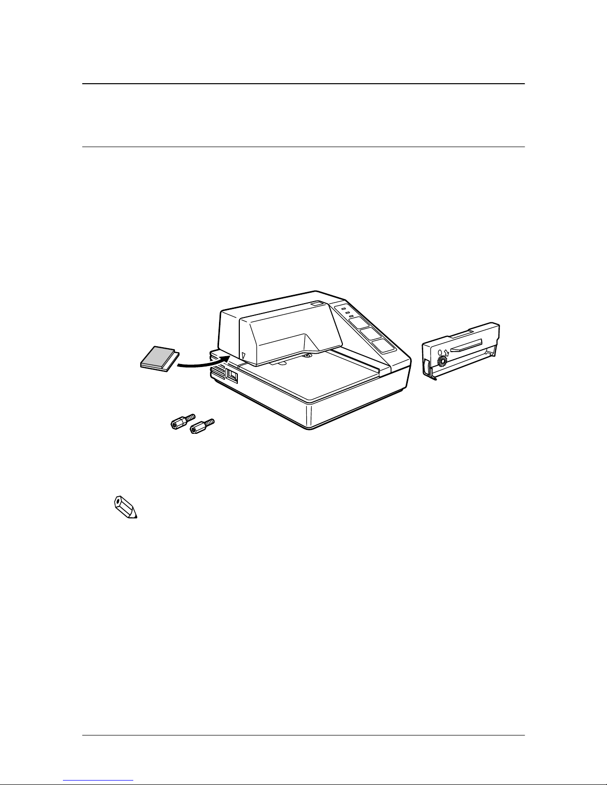
Unpacking
When you unpack the TM-U295 or TM-U295P printer, make sure
you have these items.
If any item is missing or damaged, please contact your dealer for
assistance.
Damper
Hexagonal lock screws (2 pcs)
(only for the TM-U295)
Note:
See the Note on page 1-3 for information about the screws.
Ribbon cassette
Installation 1-1
Page 13
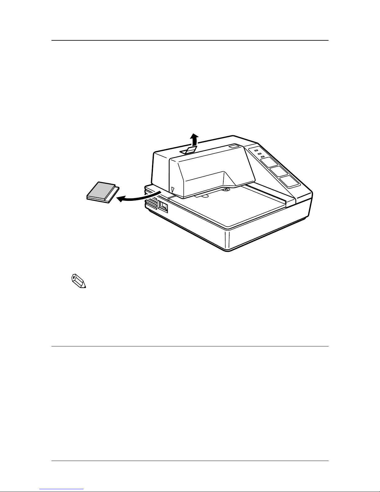
Removing the Transportation Damper
The prin te r is protect e d during shi pping by a tr ansportati on
damper t ha t must be removed before you turn on the printer.
1. Pull the damper out and remove the strip of tape from the top
of the printer, as shown below.
Note:
If you ever ship or store your printer, prepare it by performing these
steps: turn on the printer, press the RELEASE button, press the
FORWARD button, turn off the printer, and put the transportation
damper back where it was when you received the printer.
Connecting the Printer to the Computer
You need an appropriate interface cable to connect your computer
to the printer.
1-2 Installation
Page 14
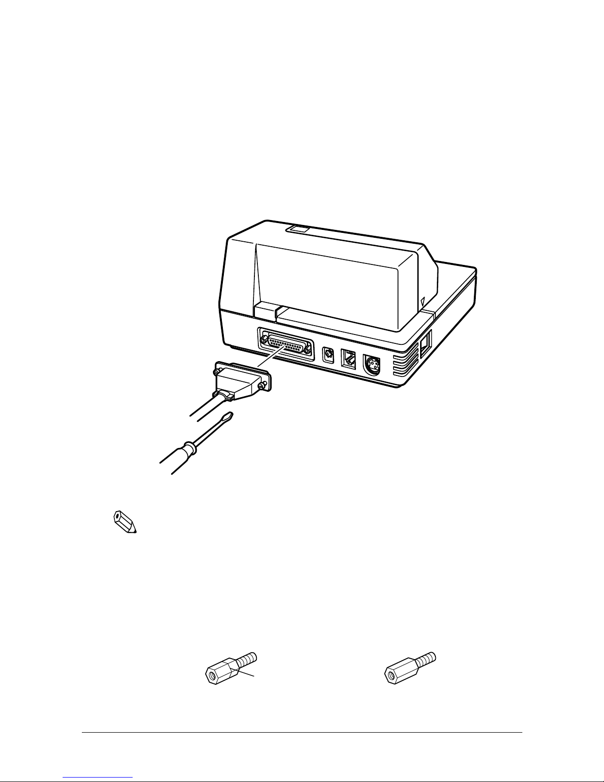
TM-U295
You need an appropriate serial interface cable to connect your
computer to the printer.
1. Make sure that the printer a nd the computer are turned off.
Then p lug the cabl e into the connector on the back of the
printer, as shown.
Note:
Your printer comes with inch-type hexagonal lock screws installed.
If you plan to use an interface cable that requires millimeter-type
lock screws, replace the inch-type screws with the enclosed
millimeter-type screws by using a hex screwdriver (5 mm). To
distinguish the two types of screws, see the illustration below; the
screw on the right is the millimeter type.
TM-T85 / U/G / fig.2-07
95/03/06
Notch (one or more lines)
Crestec
Installation 1-3
Page 15

2. Connect the o ther end of the cable to the connector on your
computer.
TM-U295P
You need an appropriate parallel interface cable to connect your
computer to the printer.
1. Make sure that the printer a nd the computer are turned off.
Then p lug the cabl e into the co nnector on the back o f the
printer, as shown.
Note:
Squeeze the wire clips on the printer together until they lock in place
on both sides of the connector.
2. Connect the o ther end of the cable to the connector on your
computer.
1-4 Installation
Page 16

Connecting the Printer to the Drawer
Plug the drawer cable into the drawer kick-out connector on the
back of the printer next to the compute r interface connector.
TM-U295
TM-U295P
CAUTION:
Do not connect a telephone line to the drawer kick out
connector.
Installation 1-5
Page 17

Den Drucker an die Lade anschließen
Das Kabel der Lade an die Schnappsteckerbuchse (neben der
Schnittstellenbuchse) an der Hinterseite des Druckers anschließen.
TM-U295
TM-U295P
CAUTION:
Kein Telefonkabel an die Schnappsteckerbuchse
anschließen.
1-6 Installation
Page 18

Grounding the Printer
You need an appropriate ground wire to ground your printer.
Recommended wire is described below.
Thickness of wire: AWG 18 or equivalent
Diameter of terminal to be attached: 3.2
1. Make sure that the printer i s turned of f.
2. Connect the ground wire to the printer using the FG screw o n
the back of the printer, as shown.
TM-U295
TM-U295P
Installation 1-7
Page 19

Connecting the Power Supply
This printer requires an external power supply. The EPSON Power
Supply PS-150 is recommended.
CAUTION:
Using an incorrect power supply can cause serious damage
to the printer.
1. Make sure that the power supply is turned off.
2. Plug the power supply’s cable int o the printer’s conne ctor as
shown below. Note that the fla t side of th e connector faces up.
TM-U295
TM-U295P
1-8 Installation
Page 20

3. Plug the power cord into an outlet.
Installing the Ribbon
Be sur e to use a ribbon cassette that meets the printer’s
specifications. The EPSON ERC-27 is recommended.
Note:
For instructions on replacing a used ribbon, see Chapter 2.
1. Turn the printer on using th e power switc h on its left side.
2. Press the RELEASE button to turn th e light on. This puts the
printer in the paper release mode.
3. Turn the printer off.
Installation 1-9
Page 21

CAUTION:
Be sure to perform the steps above because it is necessary to
make sure that the printer is in the paper release mode
before you install the ribbon cassette.
4. Open the printer cover by slightly pressing the ridges on the
top left an d pulling th e cover forward, as shown in the
illustration below.
5. Check to see that the ribbon in the cassette is not creased or
twisted. Then turn the fee d knob in th e di re ction of the arrow
on the ri bbon cass e tte to take up any slack in the ribbon.
1-10 Installation
Page 22

6. Care fully insert the ribbon cassette in the printer as shown in
the illustrat ion below. Notice exa ctly wher e the ribb on must go.
7. Then push firmly on the right side and then the left side of the
ribbon cartridge until each side clicks into place.
Installation 1-11
Page 23

8. To p ut the cove r back on the printer, first align the left and
insert the tab on the top; then press the bottom until it clicks
into place, as shown below.
Inserting Paper
Note:
Do not use wrinkled or curled paper. For full information and
specifications on the paper you can use, see Chapter 4.
To insert paper, follow these steps:
1. Make sure that a ribbon cassette is installe d in the prin ter.
2. Turn on the printer. The POWER light comes on.
3. Press the RELEASE button. The RELEASE light comes on, which
indicate s that the pri nter is in t he pa per release mode. In this
mode, the p ri nter can accept paper and paper ca n be removed
from it.
1-12 Installation
Page 24

4. Insert the paper from e ither th e front or the side , as shown in
the illustrati on below. Insert the paper into the printer until it is
stopped by the form stopper. The markings on the side of the
printer ca n also be us e d to judge how far to inse rt paper.
5. Check the PAPER OUT light. When you i nsert the paper
correctly, the PAPER OUT light goes out. If the PAPER OUT light
is still on, remove the paper and re-insert it.
Running the Self Test
Any time that you w ant to chec k the performance of y our printer
you c a n ru n t he s e lf test descri be d b el ow . Th i s sh o w s w het h e r yo ur
printer is working correctly. It is independent of any other
equipment or software.
The self test checks the control cir cui ts, printe r mechan is ms, print
quality, RAM, ROM version, and DIP switch settings.
To perform the self test, follow the steps below:
1. Insert a sheet of paper following the instructions on page 1-12.
2. Turn of f the printer.
Installation 1-13
Page 25

3. While holding down the RELEASE button, turn the printer back
on.
4. Remove your finger from the RELEASE bu tton. The printer
prints th e current pri nter settings and then eject the paper.
5. Press the RELEASE button to eject the paper completely a nd
insert ne w paper to begin the second part of the test.
After the printer pri nts a patter n, it prints the followin g message:
***completed***
The prin te r ejects the paper; then enters th e normal mode.
Setting the DIP Switches
You can change sever al interface settings by cha nging the DIP
switch settings. If you ne e d to change any of these settings, follow
the steps below:
1. Make sure that the printer i s o ff.
1-14 Installation
Page 26

2. Turn the prin te r over and locate the DIP switch e s, as show n
below.
3. Notice that ON is marked on the set of sw itches. Use tweez ers
or another narrow tool to move the switches.
4. Use th e following tables to s e t the DIP switches.
Installation 1-15
Page 27

TM-U295
Switch Function ON OFF
1 Data reception error Ignored Prints”?”
2 Receive buffer capacity 35 bytes 512 bytes
3 Handshaking XON/XOFF DTR/DSR
4 Word length 7 bits 8 bits
5 Parity check Yes No
6 Parity selection Even Odd
7
8
9 Pin 6 reset signal Used Not used
10 Pin 25 reset signal Used Not used
Transmission Speeds
See Transmission Speeds table below.
Speed in Bits per Second SW 7 SW 8
1200 ON ON
2400 OFF ON
4800 ON OFF
9600 OFF OFF
1-16 Installation
Page 28

TM-U295P
Switch Function ON OFF
1 Auto-line feed
2 Receive buffer capacity 35 bytes 512 bytes
3Undefined
4Undefined
5Undefined
6Undefined
7Undefined
8Undefined
9Undefined
10
Reserved. Setting must
not be changed
Normally
enabled
Normally
disabled
Note:
If you change any DIP switch settings while the printer is turned
on, the new settings will not take effect until you turn the printer off
and back on or reset it.
Installation 1-17
Page 29

Chapter 2
Using the Printer
The control panel has three buttons and three li ghts.
Buttons
All three of t hese buttons can be disable d or enabled by the ESC c 5
command.
RELEASE
Pre ssing this bu tton mo ve s the roller s so t hat pap e r c a n b e insert ed
or removed.
REVERSE
Feeds the paper backward based on the line feed amount set by
ESC 2 and ESC 3.
FORWARD
Feeds the paper forward based on the line feed amount set by
ESC 2 and ESC 3.
You can also use the
See Cha p te r 1 for de tails.
Indicator Lights
POWER
This light is on whenever power is supplied to the printer.
RELEASE
button to st art a self t est.
Using the Printer 2-1
Page 30

RELEASE
This light is on when the printer is in the pa per release mode and it
is off whe n the printe r is in the clamp mode. Paper can be i nserted
only when the printer is in the paper release mode.
This light blinks to indicate an error condition in the following
cases:
❏ Paper jam
❏ Home position error
❏ Timing er ror
❏ Drive c ir cui t e rror
❏ Power supply volt a ge error
If this lig ht blinks, turn off the pr inter, make sure tha t no paper is
jammed in it, and then turn it back on. If the light is still blinking,
contact a qualified service person.
PAPER OUT
This light is on when paper is not inserted or is not inserted
correctly.
Replacing a Used Ribbon
When y our printing is not dark e nough, it is time to repl ace the
ribbon.
First follow steps 1 through 4 in the “Installing the Ribbon” in
Chapter 1.
2-2 Using the Printer
Page 31

Then remove the used ribbon by grasping the handle and pulling
straight out, as shown by the arrow in the illustration below.
Then follow the rest of the steps in “Installing the Ribbon” in
Chapter 1.
Using the Printer 2-3
Page 32

Chapter 3
Troubleshooting
This cha p ter gives the solutions to some printe r problems.
Power problems
The POWER light does not come on.
Make sure that the po wer suppl y cables are correctly plugged into
the printe r, the pow e r unit, and to the power outlet.
Make sure that pow e r is supplied to the power outlet. If the outlet
is controlled by a switch or timer, use another outlet.
Printing problems
The PAPER OUT light is on and nothing is printed.
If the PAPER OUT light is on, the paper is not inserted or is n ot
inser ted correctly.
The RELEASE light is flashing and nothing is printed.
This indicates an error condition. Turn off the printer, make sure
that no paper is jammed in it, and then turn it back on. If the
RELEASE light is still flashing, contact a qualified service person.
Troubleshooting 3-1
Page 33

Chapter 4
Reference Information
Printing Specifications
Printing Method: Imp act dot matrix
Head Wires 7-pin shuttle type
Printing Direction: Unidirectional
Lines per second 5 x 7 font: 1.9 to 2.3
7 x 7 font: 1.9 to 2.3
Characters per line 5 x 7 font: 35
7 x 7 font : 42
Characters per inch: 5 x 7 font: ANK: 0.63
Graphics: 0.315
7 x 7 font: ANK: 0.63
Graphics: 0.315
Paper feed speed: Approximately 12.5 lines (52.5 mm
(2.10”))/second
(When the ESC d and FF commands are
used.)
Character Specifications
Number of
characters
Alphanumeric characters: 95
Extended graphics: 128 x 3
International characters: 32
Reference Information 4-1
Page 34

Character structure: 5 x 7 with 1-dot spacing (normal dot)
7 x 7 with 3-dot spacing (half dot)
Character size: 5 x 7 font:
ANK: 1.6 mm (.063”) x 2.9 mm (.114”)
Graphics: 1.9 mm (.075”) x 2.9 mm
(.114”)
7 x 7 font:
ANK: 1.3 mm (.051”) x 2.9 mm (.114”)
Graphics: 1.6 mm (.063”) x 2.9 mm
(.114”)
4-2 Reference Information
Page 35

Paper Specifications
Paper type: Norma l (high qu a lity), pressure
Total thickness: Single-play paper: 0.09 to 0.25 mm
Paper size: 80 mm (W) × 69 mm (L) to 182 mm
sensitive, and carbon copy papers
(.0035 to .0098”)
Copy paper: 0.09 to 0.35 mm (.0035
to .0138”)
(W) × 257 mm (L) (3.15” × 2.72” to
7.17” × 10.12”) Up to the European
B5 size.
Copy capability and
paper thickness:
No copies
(singleply):
Combination of
normal
paper and
pressure
sensitive
paper:
0.09 to 0.25 mm
(.0035 to .0098”)
(135 kg paper or
equivalent)
3 sheets
maximum (1
original and 2
copies) (0.09 to
0.35 mm (.0035 to
.0138”))
Backing paper:
0.07 to 0.20 mm
(.0028 to .0079”)
Copy and original
paper:
0.04 to 0.07 mm
(.0016 to .0028”)
Carbon copy
paper:
Approximately
0.035 mm (.0014”)
Reference Information 4-3
Page 36

Copy capability and
ambient
temperature for
printing:
Relationship between ambient temperature and
number of copies
Number of copies Ambient temperature (print mode)
Original + 1 to 2 copies 5° to 40°C (41° to 104°F)
Notes on slip paper
❏ Slip paper should be flat, without curls, wrinkles, or camber,
especially at the paper edges. Otherwise, the paper may
become ink stained.
Copying capabi lity is i nfl uenc ed by
the ambient temperature. Printing
must b e performed under the
conditions, described in a Table
below:
❏ When u s ing multiply-p ly ca rbon cop y paper, it should be fla t
and the glue area should be as small as possible.
❏ Glue area should be located at the top or left edge of the slip
paper.
❏ Since TOF and BOF sensors are optical sensors, paper having
holes at the sen sor p osi tions or tr anslucen t paper shou ld n ot be
used normallly. When using these papers, be sure to disable the
paper sens o rs by ESC c 4.
❏ When using slip paper of 80 mm (3.15”) long or less, load the
paper so that it is fed straight.
❏ Use thinner paper (N30 or equivalent) betwe e n the top and
bottom sheets of multi-ply paper. If thi ck paper is used, the
copy capability is lowered.
4-4 Reference Information
Page 37

Printing position
Adjustable
Reverse paper feed
Forward paper feed
Paper feed roller
NOTE 1. Mechanical form stopper
NOTE 2. TOF sensor (fixed)
Printing position at minimum top margin
65.84 (2.59")
First printing position
Last printing position
NOTE 2. BOF sensor (fixed)
12.5 (.49")
5 (.20")
12.5 (.49")
2.3 (.09")
NOTE 4. 13.8 (.54")
10 (.39")26.5 (1.04")
NOTE 3. 5.3 (.21")
27.3 (1.07")
NOTE 5. 15.5 (.61")
Notes
1. The mechanical form stopper is adjustable in the range 26.5 to
2. The TOF and BOF sensors are fixed and cannot be adjusted.
3. After slip paper is set at the mech anical form stopper, the top
4. When e je ction feed in g is not performed after print in g, printing
5. Whe n e jection f eeding is performed after pri nting, the paper
36.5 mm (1.04 to 1.44”).
margin can be shortened up to 21.2 mm (.83”) by feeding the
paper backw ar ds (ejection feeding).
can be p e rformed up to the position at which the pap er edge is
no longer h eld by the pap er feed roller ( 13. 8 mm (.54”) f r om th e
paper edge).
can be fed forward up to 11.8 mm (.46”) (28 dots) after the
bottom e dge is detecte d.
Reference Information 4-5
Page 38

Electrical Specifications
Supply voltage: +24 VDC ± 10%
Current consumption: Operating
(except for
drawer kickout):
Mean - approx.
600 mA at 24
VDC (full-column
printing a nd data
transmission of
ANK characters)
Peak - approx.
5.5 A at 24 VDC
(full-column
printing a nd data
transmission of
ANK characters)
Standby: approx.
100 mA (at 24
VDC, 25°C (77 °F)
4-6 Reference Information
Page 39

EMI and Safety Standards
EMI standards
(measured when
using the printer with
the Epson PS-150):
Safety standards: UL1950-2TH-D3 (Recognized
Reliability
Life: 3,000,000 lines
FCC: Class A
CE marking:
component)
CSA950-D3 (Recognized component)
EN60950 (IEC950 2TH)
❑ End of Life is defined as the point
at which the printer reaches the
beginning of the Wearout Period.
MTBF: 180,000 hours
❑ Failure is defined as Random
Failure occu rring at the time of the
Rand om Failure Period.
MCBF: 7,000,000 lines
❑ This is an average failure interval
base d on failures rela ting to
wearout and random f ailur es u p to
the life of 3 million lines.
Reference Information 4-7
Page 40

Environmental Conditions
Temperature: Operating: 5° to 40°C (41° to
Storage: -10° to 50°C (14°
Humidity: Operating: 30 to 85% (with
Storage: 30 to 90% (with
104°F)
to 122°F) (except
for ribbon and
paper)
no condensation)
no condensation,
except fo r ri bbon
and paper)
Interface Specifications
Serial interface: RS-232 compatible
Parallel interface: IEEE 1284 compatible (Nibble/Byte
Note:
The interface is a factory installed option. One of the interfaces
(serial or parallel) is already installed.
Note:
Refer to the EPSON TM-U295/U295P Specification for details.
Modes)
4-8 Reference Information
Page 41

Chapter 5
Commands
Command Notation
[Name] The name of the command.
[Format] The code sequence.
ASCII indicates the ASCII equivalents.
Hex indicates the hexadecimal equivalents.
Decimal indicates the decim al equivale nts.
[ ]k indicates the contents of the [ ] should be repeated k times.
[Range] Gives the allowable ranges for the arguments.
[Description] Describes the function of the command.
[Notes] Provides important information on setting a nd using the pr inter
command, if necessary.
[Default] Gives the default values, if any, for the command parameters.
[Reference] Lists related commands.
[Example] Provides examples using the command.
The numbers denoted by < >H are hexadecimal.
The numbers denoted by < >B are binary.
The numbers denoted by < > are decimal.
NOTE: The phrase "beginning of a line" in command descriptions assumes
that the following condition has bee n met:
• P rint data, including spaces skipped by HT, is not in the current
print buffer.
Commands 5-1
Page 42

Control Commands
HT
[Name] Horizontal tab
[Format] ASCII HT
Hex 09
Decimal 9
[Description] Moves the print position to the next horizontal tab position.
[Notes] • Horizontal tab positions are set with
• Ignored unless the next horizontal tab position has been set.
• Th e default tab positions are at intervals of 8 characters in the
5 x 7 font 9th column, 17th column, 25th column,. . . ).
[Reference]
LF
[Name] Print and line feed
[Format] ASCII LF
[Description] Prints the data in the print buffer and feeds one line based on the
[Note] This command sets the print position to the beginning of the line.
[Reference]
ESC D
Hex 0A
Decimal 10
current line spacing.
ESC 2, ESC 3
ESC D
.
FF
[Name] ➀Print and eject sheet (in standard mode)
➁Print and return to standard mode (in page mode)
[Format] ASCII FF
Hex 0C
Decimal 12
This command functions differently depending on the printer mode selected.
➀When standard mode is selected:
[Description] Prints the data in print buffer and ejects the sheet.
[Notes] • When the eject length has been set by
sheet based on the current eject length. Otherwise, the printer
ejects the sheet completely. If a paper out is detected during
ejection, the printer stops ejecting the sheet even if the specified
amount of paper has not been ejected.
• The ejecting direction is specified by
[Reference]
➁When page mode is selected:
ESC F, ESC C
ESC C
ESC F
, the printer ejects the
.
5-2 Commands
Page 43

[Description] Prints the data in the print buffer and returns to standard mode.
[Notes] • The buffer data is deleted after being printed.
• Th e printer does not execute paper ejection.
• Th is comman d sets the print position to the beginning of the line.
[Reference] ESC L
CR
[Name] Print and carriage return
[Format] ASCII CR
Hex 0D
Decimal 13
[Description] When auto-line feed is enabled, this command functions in the same
way as LF. When auto-line feed is disable d, this command is i gnor ed.
[Notes] • This command sets the print position to the beginning of the line.
• This command is available only with a parallel interface and is
ignored with a serial interface.
DLE EOT
[Name] Real-time status transmission
[Format] ASCII DLE EOT
[Range] 1≤ n ≤ 3, n = 5
[Description] Transmits the selected printer status specified by n in real time,
[Notes] • The printer executes this command upon receiving it.
n
n
Hex 10 04
Decimal 16 4
according to the following parameters:
n
= 1: Transmit printer status
n
= 2: Transmit off-l ine status
n
= 3: Transmit error status
n
= 5: Transmit slip paper status
• W hen transmitting status, the printer transmits only 1 byte
without confirming the co ndition of the DSR signal.
• With the serial interface model, this command is executed even in
off-line or receive buffer-full state. However, with the parallel
interface model, this command is not executed in off-line or
receive buffer-full state because the printer is busy and unable to
receive this command from the host.
• Th e status is transmitted whenever the data sequence of
<10>H<04>H<n> (1 ≤ n ≤ 3, n = 5) is received even if it appears as
part of another command. For example,
In ESC ✻
d3=<1>H
m n L n
H [d] n L+256
n
n
H, d1=<10>H, d2=<04>H,
✕
n
Commands 5-3
Page 44

• Th is comman d should not be used within the data sequence of
another command that consists of 2 or more bytes. For example,
If you attempt to transmit ESC 3 n to the printer, but DTR (DSR
for the host computer) goes to MARK before n is transmitted
and then DLE EOT 3 interrupts before n is received, the code
<10>H for DLE EOT 3 is processed as the code for ESC 3
<10>H.
• When Auto Status Back (ASB) is enabled using the GS a
command, the stat us tr an s mit te d by the DLE EOT command an d
the ASB status must be differentiated.
•If the n is out of the specified range, the printer ignores this
command.
n
= 1: Printer status
Bit Off/On Hex Decimal Function
0 Off 00 0 Not used. Fixed to Off.
1 On 02 2 Not used. Fixed to On.
Off 00 0 Drawer kick-out signal is LOW (connector pin 3)
2
On 04 4 Drawer kick-out signal is HIGH (connector pin 3)
Off 00 0 On-line.
3
On 08 8 Off-line.
4 On 10 16 Not used. Fixed to On.
Off 00 0 Undefined.
5
On 20 32 Undefined.
Off 00 0 Undefined.
6
On 40 64 Undefined.
7 Off 00 0 Not used. Fixed to Off.
n
= 2: Off-line status
Bit Off/On Hex Decimal Function
0 Off 00 0 Not used. Fixed to Off.
1 On 02 2 Not used. Fixed to On.
Off 00 0 Undefined.
2
On 04 4 Undefined.
5-4 Commands
Page 45

Bit Off/On Hex Decimal Function
Off 00 0
3
On 08 8 Paper is being fed by the paper feed button.
4 On 10 16 Not used. Fixed to On.
Off 00 0 No paper-end stop.
5
On 20 32 Printing stops due to paper end.
Off 00 0 No error.
6
On 40 64 Error occurs.
7 Off 00 0 Not used. Fixed to Off.
Paper is not being fed by using the paper feed
button.
Bit 5: On (printing stops due to paper-end) indicates printing stops as a
result of the paper state and TOF or BOF sensor selected by ESC c 4.
n
= 3: Error status
Bit Off/On Hex Decimal Function
0 Off 00 0 Not used. Fixed to Off.
1 On 02 2 Not used.Fixed to On.
Off 00 0 Undefined.
2
On 04 4 Undefined.
Off 00 0 Undefined.
3
On 08 8 Undefined.
4 On 10 16 Not used. Fixed to On.
Off 00 0 No unrecoverable error.
5
On 20 32 Unrecoverable error occurred.
Off 00 0 Undefined.
6
On 40 64 Undefined.
7 Off 00 0 Not used. Fixed to Off.
Commands 5-5
Page 46

n = 5: Slip p aper st atus
Bit Off/On Hex Decimal Function
0 Off 00 0 Not used. Fixed to Off.
1 On 02 2 Not used. Fixed to Off.
2 Off 00 0 Slip paper selected.
Off 00 0 Does not wait for slip paper insertion.
3
On 08 8 Waits for slip paper insertion.
4 On 10 16 Not used. Fixed to On.
Off 00 0 Slip is detected by the BOF sensor.
5
On 20 32 Slip is not detected by the BOF sensor.
Off 00 0 Slip is not detected by the TOF sensor.
6
On 40 64 Slip is detected by the TOF sensor.
7 Off 00 0 Not used. Fixed to Off.
Bit 3: Becomes Off (not waiti n g) just befo re actual slip s e l e ction ta kes p la c e
after slip paper is detected
Bit 5 and 6: Transmits the current status of the TOF and BOF sensors.
[Reference] ESC u, ESC v, GS a
CAN
[Name] Cancel print data in page mode
[Format] ASCII CAN
Hex 18
Decimal 24
[Description] In page mode, deletes all the print data in the current printable area.
[Notes] • This command is enabled only in page mode.
• If data that existed in the previously specified printable area also
exists in the currently specified printable area, it is deleted.
[Reference] ESC W
ESC SP
[Name] Set right-side character spacing
[Format] ASCII ESC SP
[Range] 0 ≤ n ≤ 32
n
Hex 1B 20
Decimal 27 32
n
n
n
5-6 Commands
Page 47

[Description] Sets the character spacing for the right side of the character.
[Notes] • The right-side character spacing for double-width mode is twice
the normal value.
• The chara cter spac ing is set in increment of half do t.
• In page mode, the actual dot positions shift by half dot.
• This command sets values independently in standard mode and
in page mode.
[Default]
n
= 0
ESC !
n
[Name] Select print mode(s)
[Format] ASCII ESC !
Hex 1B 21
Decimal 27 33
n
n
n
[Range] 0 ≤ n ≤ 255
[Description] Selects print mode(s) using n as follows:
Bit Off/On Hex Decimal Function
Off 00 0 Character font 5
0
On 01 1 Character font 7
Off 00 0 Undefined.
1
On 02 2 Undefined.
Off 00 0 Undefined
2
On 04 4 Undefined.
Off 00 0 Undefined.
3
On 08 8 Undefined.
✕ 7 selected.
✕ 7 selected.
Off 00 0 Double-height mode not selected.
4
On 10 16 Double-height mode selected.
Off 00 0 Double-width mode not selected.
5
On 20 32 Double-width mode selected.
Off 00 0 Undefined.
6
On 40 64 Undefined.
Off 00 0 Underline mode not selected.
7
On 80 128 Underline mode selected.
Commands 5-7
Page 48

[Notes] • The printer can underline all characters (including the right-side
character spacing), but cannot underline the space set by an HT.
• When both double-height and double-width modes are selected,
quadruple size characters are printed.
• On ly setting of underline mode specification have effect in page
mode.
• Only setting of 7 × 7 font specification have effect in page mode.
[Default]
n
= 0
ESC %
[Name] Select/cancel user-defined character set
[Format] ASCII ESC %
[Range] 0 ≤ n ≤ 255
[Description] Selects or cancels the user-defined character set.
[Notes] • When the user-defined character set is cancelled, the internal
[Default]
[Reference ] ESC &
ESC &
[Name] Define user-defined characters
[Format] ASCII ESC &
[Range]
[Description] Defines user-defined characters.
n
n
Hex 1B 25
Decimal 27 37
When the Least Significant Bit (LSB) is 0, the user-defined character
set is cancelled.
When the LSB is 1, the user-defined character set is selected.
character set is automatically se l ected.
n
= 0
]
y c1 c2 [X [d] y
Hex 1B 26
Decimal 27 38
y
= 1
32 ≤ c1 ≤
0 ≤ x ≤ 6 (5
0 ≤ x ≤ 10 (7
0 ≤
•The y specifies the number of bytes in the vertical direction.
c1
•
specifies the final code. When only one character is desired, use
= c2.
• The allowable ch ar ac te r co de r an ge is fr o m d eci ma l code 32 to 12 6.
•x specifies the number of dots in the horizontal direction.
c2
d1 ... dy
specifies the beginning character code for the definition, and c2
x
✕
≤ 126
✕ 7 font)
✕ 7 font)
x
✕
≤ 255
c2-c1
+1
n
n
y c1 c2 [x [d] y
y c1 c2 [x [d] y
y c1 c2 [x [d] y
✕
✕
✕
x] c2
x] c2
x] c2
- c1 + 1
- c1 + 1
- c1 + 1
c1
5-8 Commands
Page 49

•d is the dot data for the characters. The dot pattern is in the
horizontal direction from the left side. Any remaining dots on
right side are blank.
• The data to define a user-defined character is (y × x) bytes.
• Set a corresponding bit to 1 to print a dot or to 0 to not print a dot.
• It is possible to define multiple characters for consecutive
character codes.
[Notes] • After user-defined characters are defined, they are available until
another definition is made; ESC @ is executed; the printer is reset;
or the power is turned off.
• If the values of y, c1, c2, or x are out of the specified range, the
printer ignores the command and processes the following data as
normal data.
•In 7 × 7 font, horizontally adjacent dots cannot be printed. Define
the character so that it does not include horizontally adjacent dots.
[Default] The internal character set
[Reference] ESC %
[Example]
•5 × 7 font when the dot pattern for code 32 (20H) is defined as shown below:
p1 p2 p3 p4 p5 p6
MSB
LSB
ASCII code ESC &
Hex code 1B 26 01 20 20 05 3E 48 88 48 3E
y c1 c2 x p1 p2 p3 p4 p5
Commands 5-9
Page 50

•7 × 7 font when the dot pattern for code 32 (20H) is defined as shown below:
p1 p2 p3 p4 p5 p6 p7 p8 p9 p10
MSB
LSB
ASCII code ESC &
y c1 c2 x p1 p2 p3 p4 p5 p6 p7
Hex code 1B 25 01 20 20 07 1E 20 48 80 48 20 1E
5-10 Commands
Page 51

ESC ✽
m nL n H [d]k
[Name] Select bit-image mode
[Format] ASCII ESC
Hex 1B 2A
Decimal 27 42
[Range]
m
= 0, 1
✽
nL nH [d]k
nL nH [d]k
nL nH [d]k
0 ≤ nL ≤ 255
0 ≤ nH ≤ 3
0 ≤ d ≤ 255
k
= nL + nH x 255
[Description] Selects a bit-image mode using m for the number of dots specified by
nL
and nH, as follows:
Vertical direction Horizontal direction
m
Mode
0 8-dot single-density 8 60 DPI 80 DPI 210
1 8-dot double-density 8 60 DPI 160 DPI 420
The number
of dots
Dot
density
Dot
density
Maximum
number of dots
The number of dots in the horizontal direction depends on the
prin ti ng area an d the p r in ti ng dir e ct io n spec i fied by
.
T
ESC W
and
ESC
[Notes] • The nL and nH indicate the number of dots of the bit image in the
horizontal direction. The number of dots is calculated by nL +
✕
256.
nH
• If the bit-image data input exceeds the number of dots to be
printed on a line, the excess data is ignored.
•d indicates the bi t-image data. Set a corres pond i ng bit to 1 to print
a dot or to 0 to not print a dot.
• If the values of m and nH are out of the specified range, the
following data is processed as normal data.
• After printing a bit image, the printer returns to normal data
processing mode.
• In page mode, double density bit image data is not available.
• The relationship between the image data and the dots to be
printed is shown on the next page.
Commands 5-11
Page 52

• The relationship between the image data and the dots to be printed is as follows:
0
12
Print data
Top
Bottom
Bit image data
4
5
6
7
3
ESC 2
[Name] Select 1/6-inch line spacing
[Format] ASCII ESC 2
Hex 1B 32
Decimal 27 50
[Description] Selects 1/6-inch line spacing.
[Note] The line spacing can be set independently in standard mode and in
page mode.
[Reference]
ESC 3
ESC 3
[Name] Set line spacing
[Format] ASCII ESC 3
[Range] 0 ≤ n ≤ 255
[Description] Sets the line spacing to n/60 inches.
[Notes] • This command sets values independently in standard mode and
[Default]
[Reference ]
ESC =
[Name] Set device
[Format] ASCII ESC =
n
n
5-12 Commands
Hex 1B 33
Decimal 27 51
in page mode.
n
= 10 (1/6 inch)
ESC 2
n
n
n
n
Page 53

Hex 1B 3D
Decimal 27 61
n
n
[Range] 0 ≤ n ≤ 3
[Description] Selects device to which host computer sends data, using n as follows:
Bit Off/On Hex Decimal Function
Off 00 0 Printer disabled.
0
On 01 1 Printer enabled.
Off 00 0 Undefined.
1
On 02 2 Undefined.
Off 00 0 Undefined.
2
On 04 4 Undefined.
Off 00 0 Undefined.
3
On 08 8 Undefined.
Off 00 0 Undefined.
4
On 10 16 Undefined.
Off 00 0 Undefined.
5
On 20 32 Undefined.
Off 00 0 Undefined.
6
On 40 64 Undefined.
Off 00 0 Undefined.
7
On 80 128 Undefined.
[Notes] • When the printer is not selected, the printer ignores all received
data until it is selected by this command.
• Even if the printer is disabled, it may go off-line due to printer
operation.
[Default]
n
= 1
ESC @
[Name] Initialize printer
[Format] ASCII ESC @
Hex 1B 40
Decimal 27 64
[Description] Clears the data in the print buffer and resets the printer mode to the
mode that was in effect when the power was turned on.
Commands 5-13
Page 54

[Notes] • The DIP switch settings are not checked again.
• Th e data in the receive buffer is not cleared.
• The macro definition is not cleared.
ESC C
[Name] Set cut sheet eject length
[Format] ASCII ESC C
[Range] 0 ≤ n ≤ 127
[Description] Sets the eject length for a cut sheet to n lines.
[Notes] • When n = 0, no eject length is set.
[Default] n = 0
[Reference]
n
n
Hex 1B 43
Decimal 27 67
• Th e previously specified eject length does not change, even if the
line spac i ng changes.
• This command is av ailable only when FF is executed.
FF
n
n
ESC D [n] k NUL
[Name] Set horizontal tab positions
[Format] ASCII ESC D [n] k NUL
Hex 1B 44 [n] k 00
Decimal2768[
[Range] 1 ≤ n ≤ 255
0 ≤ k ≤ 32
[Description] Sets horizontal tab positions.
•n specifies the column number for sett ing a horizontal t ab position
from the beginning of the line.
• Th is comman d cancels the previous horizontal tab settings.
•n = column number to be set - 1. When setting n = 8, the print
position is moved to c olumn 9 by sending HT.
•k indicates the total number of horizontal tab positions to be set.
• Th e horizontal tab position is stored as an absolute value of
n
✕
[char ac ter wi dth
character width includes the right-side character spacing, and
double -width characte r s are set with twice the width of normal
characters. Also, when character is enlarged in the horizontal
direction in page mode, the horizontal position is set as the same
way as in standar d mode.
•Transmit [n]k in ascending order and place a NUL code 0 at the
end.
•
ESC D NUL
after clearing tabs is ignored.
cancels all horizontal tab positions. An HT received
] measured from the beginning of the line. The
n
] k 0
5-14 Commands
Page 55

[Notes] • Up to 32 tab positi ons (k = 32) can be set. Data exceeding 32 tab
positions is processed as normal data.
•When [n]k is less than or equal to the preceding value [n]k-1, t ab
setting is finished and the following data is processed as normal
data.
•When [n]k exceeds the number of characters printable on one line,
the tab position set is equal to the maximum printable column
plus 1.
• The previously specified horizontal tab positions do not change,
even if the character width changes.
• Th e right-side spacing is set independently in standard and page
modes. The horizontal tab setting is set by using amount of the
right-side spacing of the mode used.
[Default] The default tab positions are at intervals of 8 characters (columns 9,
17, 25,...) for the default character font.
n
n
n
Hex 1B 46
Decimal 27 70
• When the LSB of n is 0, reverse eject is canceled and forwqrd eject
is set.
• When the LSB of n is 1, reverse eject is set.
automatically.
n
= 0
FF
Hex 1B 4A
Decimal 27 74
inches.
n
n
n
n
n
ESC F
[Name] Set/cancel cut sheet reverse eject
[Format] ASCII ESC F
[Range] 0 ≤ n ≤ 255
[Description] Sets or cancels the cut sheet reverse eject specified by FF.
[Note] When n cancels reverse eject, this command sets forward ejection
[Default]
[Reference ]
ESC J
[Name] Print and feed paper
[Format] ASCII ESC J
[Range] 0 ≤ n ≤ 255
[Description] Prints the data in the print buffer and feeds the paper by n/60
[Note] Sets the print position to the beginning of the line.
ESC K
[Name] print and revers feed
n
Commands 5-15
Page 56

[Format] ASCII ESC K
Hex 1B 4B
Decimal 27 75
[Range] 0 ≤ n ≤ 255
[Description] Prints the data in the print buffer and feeds the paper by n/60 in ches
in the reverse direction.
[Notes] • This comm and is available on ly in standard mode.
• The setting values do not remain.
• After printing is completed, this command sets the print position
to the beginning of the line.
n
n
n
ESC L
[Name] Select page mode
[Format] ASCII ESC L
Hex 1B 4C
Decimal 27 76
[Description] Switches from standard mode to page mode.
[Notes] • This comm and is enabled only when inp ut a t the beginn ing of a
line.
• This command is available only in standard mode.
• After printing by FF is completed, the printer returns to standard
mode.
• Th is comman d sets the position where data is buffered to the
position specified by
ESC W
• In page mode, the printer buffer receives data in the printable ar ea
specified by
of FF command. The print and line feed commands, such as LF,
ESC J, ESC K, ESC d,
position from which subsequent data is buffered and do not
perform actual printing.
• In page mode, the printer porcesses data referring to normal dot.
Therefore, be careful when using half dot in standard mode.
• Only character fonts with normal dot configuration are available.
• Th is comman d switches the settings for the following commands
(in which the values can be set independently in standard mode
and page mode) to those for page mode:
In page mode, the following commands are ignored.
•
.
ESC W
Set character spacing:
Sele c t 1/6-in ch li ne sp a c in g :
Set line s p acing:
Print and reverse feed n lines:
Print and reverse feed:
ESC T
and prints the data collectively upon receipt
ESC 3
within the printable area defined by
and
ESC SP
ESC K
ESC e
, only move the print start
ESC 2
ESC e
5-16 Commands
Page 57

Double-density bit image: ESC ✻
Paper release: ESC q
• The following commands are settable but do not have any effect
in page mode.
Upside-down character mode: ESC {
7 × 7 font and underline mode specification and cancel: ESC !
• This command is effective only in standard mode.
•ESC @ command returns the printer to standard mode without
prin ti ng any data.
[Defa ult] S tandard mode
[Reference ] FF
ESC R
[Name] Select an inte rnational character set
[Format] ASCII ESC R
[Range] 0 ≤ n ≤ 10
[Description] Selects an international character set n from the following table:
n
Character set
0 U.S.A.
1France
2 Germany
3U.K.
4 Denmark I
5Sweden
6Italy
n
Hex 1B 52
Decimal 27 82
n
n
n
7Spain
8 Japan
9Norway
10 Denmark II
[Note] If the value of n is out of specified range, printer ignores the
command.
[Default]
[Reference ]
n
= 0
Character Code Tables
Commands 5-17
Page 58

ESC T
[Name] Sele ct print direction in page mode
[Format] ASCII ESC T
[Range] 0 ≤ n ≤ 3
[Description] Selects the print direction and starting position in page mode.
n
Hex 1B 54
Decimal 27 84
48 ≤ n ≤ 51
n
specifies the print direction and starting position as follows:
n
n
n
n
0, 48 Left to right
1, 49 Bottom to top
2, 50 Right to left
3, 51 Top to bottom
[Note s] • When the p rinting di r ection is changed, the pr i nt ing dir e cti o n an d
[Default]
ESC W
Print Direction Starting Position
Upper left
(A in the figure)
A
Lower left
(B in the figure)
Lower right
(C in the figure)
Upper right
(D in the figure)
print starting position for the da ta following ar e t hose specifi ed by
n
.
• Only setting of this command is effective in standard mode.
•If n is out of the specified range, this command is ignored.
n
= 0
Printing area
B
xL xH yL yH dxL dxH dyL dyH
Pape r feed direction
D
C
[Name] Set printing area in page mode
[Format] ASC II ESC W
Hex 1B 57
Decimal 27 87
[Range] 0 ≤ xL≤
dyL≤ 255, 0 ≤ dyH≤ 1 (Except for dxL=dxH=0 or dyL=dyH=0)
[Description] Sets the position and the size of the printing area.
• W hen the horizontal print start position, vertical print start
position, horizontal length, and vertical length are defined as x0,
y
0,
Each s etting for the print able area is calculated as follows:
x
0 = [(xL +
y
0 = [(yL + yH
5-18 Commands
xL xH yL yH dxL dxH dyL dyH
xL xH yL yH dxL dxH dyL dyH
xL xH yL yH dxL dxH dyL dyH
255, xH=0, 0 ≤ yL≤ 255, 0 ≤ yH≤ 1, 0 ≤ dxL≤ 255, dxH=0, 0 ≤
dx
(dot), dy (dot), respectively.
xH
✕ 256)]
✕ 256)]
Page 59

dx
dy
= [
= [
dxL
dyL + dyH
+
dxH
✕ 256]
✕ 256]
The printable area is set as shown in the figure below.
(0, 0)
Printable area of the paper
(x0, y0) dx
dy Printing area
(x0+dx-1,
y0+dy-1)
(209 dots, 479
dots)
[Notes] • The maximum printable area in the horizontal direction (x
direction) is 210 dots.
• Th e maximu m printable area in the vertical direction (y direc ti on)
is 480 dots.
• If the setting values exceed the printing area, it set to the
maximum printing area automatically, depending on the values
from xL to
dyH
.
• I f (horizontal print s tarting position + hor izontal len gth) or
(vertical print starting position + vertical length) is outside the
printable area, the maximum printing area is set to the printable
area.
• W hen the print data is buffered in the specified printing area, the
length of the printing area in both the horizontal and vertical
direction should be 8 dots or more.
• Th e printing area should accommodate to the size of the print
sheet.
• When the starting poi nt (x0, y0) exceeds the printing area, this
comm and is ignored.
• In standard mode, only setting of this command is effective.
[Default]
xL
= xH = yL = yH = 0
dxL
= 210,
dxH
= 0,
dyL
= 224,
dyH
= 1
[Reference ] CAN, ESC L, ESC T
ESC c 3
n
[Name] Select pa pe r s e nsor(s) to output paper end sign als
[Format] ASCII ESC c 3
n
Commands 5-19
Page 60

Hex 1B 63 33
Decimal279951
n
n
[Range] 0 ≤ n ≤ 255
[Description] Selects paper sensor(s) to output paper end signals, using n as
follows:
Bit Off/On Hex Decimal Function
Off 00 0 Undefined.
0
On 01 1 Undefined.
Off 00 0 Undefined.
1
On 02 2 Undefined.
Off 00 0 Undefined.
2
On 04 4 Undefined.
Off 00 0 Undefined.
3
On 08 8 Undefined
Off 00 0 TOF sensor disabled.
4
On 10 16 TOF sensor enabled.
Off 00 0 BOF sensor disabled.
5
On 20 32 BOF sensor enabled.
Off 00 0 Undefined.
6
On 40 64 Undefined.
Off 00 0 Undefined.
7
On 80 128 Undefined.
[Notes] • It is possible to select multiple sensors to output signals. Then, if
any of the sensors detects a paper-end, the paper end signal is
output.
• This command is available on ly with a par allel inter face and is
ignored with a serial interface.
n
n
= 0
[Default]
ESC c 4
[Name] Select paper sensor(s) to stop printing
[Format] ASCII ESC c 4
Hex 1B 63 34
Decimal279952
n
n
n
5-20 Commands
Page 61

[Range] 0 ≤ n ≤ 255
[Description] Selects the paper sensor(s) used to stop pri nting when a p aper-e nd is
detected, using n as follows:
Bit Off/On Hex Decimal Function
Off 00 0 Undefined.
0
On 01 1 Undefined.
Off 00 0 Undefined.
1
On 02 2 Undefined.
Off 00 0 Undefined.
2
On 04 4 Undefined.
Off 00 0 Undefined.
3
On 08 8 Undefined.
Off 00 0 TOF sensor disabled.
4
On 10 16 TOF sensor enabled.
Off 00 0 BOF sensor disabled.
5
On 20 32 BOF sensor enabled.
Off 00 0 Undefined.
6
On 40 64 Undefined.
Off 00 0 Undefined.
7
On 80 128 Undefined.
[Notes] • It is possible to select multiple sensors to stop printing. Then, if
any of the selected sensors detects a paper-end, the printer stops
printing.
• W hen a paper-end is detected, printing stops after printing and
feeding the current line. In this time, if the panel buttons are
disabled, the printer release the paper and waits the next paper
automatically.
[Default]
n
= 0
[Reference ] ESC c 5
ESC c 5
n
[Name] Enable/disable panel buttons
[Format] ASCII ESC c 5
Hex 1B 63 35
n
n
Commands 5-21
Page 62

Decimal279953
[Range] 0 ≤ n ≤ 255
[Description] Enables or disables the panel buttons.
• When the LSB of n is 0, the panel buttons are enabled.
• When the LSB of n is 1, the panel buttons are disabled.
[Notes] • When the panel buttons are disabled, none of them are usable
when the printer cover is closed.
[Default]
n
= 0
n
ESC d
[Name] Print and feed n lines
[Format] ASCII ESC d
[Range] 0 ≤ n ≤ 255
[Description] Prints the data in the print buffer and feeds n lines.
[Notes] • This command sets the print starting position to the beginning of
[Reference]
ESC e
[Name] Print and reverse feed n lines
[Format] ASCII ESC e
[Range] 0 ≤ n ≤ 255
[Description] Prints the data in the print buffer and feeds n lines in the reverse
[Notes] • The command is available only in standard mode.
n
n
Hex 1B 64
Decimal 27 100
the line.
• This command does not affect the line spacing set by
ESC 3
ESC 2, ESC 3
.
n
n
n
n
Hex 1B 65
Decimal 27 101
direction.
• Th is comman d sets the print position to the beginning of the line.
• The setting values do not remain.
n
n
ESC 2
or
f
ESC
[Name] Set cut sheet wait time
[Format] ASCII ESC f
[Range]
t1 t2
Hex 1B 66
Decimal 27 102
t1
= 0
0 ≤ t2 ≤ 64
5-22 Commands
t1 t2
t1 t2
t1 t2
Page 63

[Description] Sets the time that the printer waits for slip paper to be inserted and
the time from insertion of the sheet to the start of printing.
•t1 specifies the wait time for a cut sheet to be inserted. There is no
limitation for the wait time and the printer waits until slip paper is
inserted.
•t2 specifies the time from insertion of the sheet to the start of
printing.
• The printer starts operation [t2 × 0.1] seconds after detecting slip
paper.
[Note] When either t1 or t2 is out of the specified range, this command does
not change the previously set wait time.
[Default]
t1
= 0, t2 = 10
ESC p
[Name] Generate pulse
[Format] ASCII ESC p
[Range]
[Description] Outputs the pulse specified by
m
0, 48 Drawer kick-out connector pin 2
1, 49 Drawer kick-out connector pin 5
[Notes] • The pulse ON time is [t1
m t1 t2
m t1 t2
Hex 1B 70
Decimal 27 112
m
= 0, 1, 48, 49
0 ≤ t1 ≤ 255
0 ≤ t2 ≤ 255
follows:
Connector pin
•If m is outside the specified range, the printer ignores this
command and the following data is processed as normal data.
m t1 t2
m t1 t2
t1
and t2 to connector pin m as
✕ 2 ms] and the OFF time is [
t2
✕ 2 ms].
ESC q
[Name] Paper release
[Format] ASCII ESC q
Hex 1B 71
Decimal 27 113
[Description] Releases the paper
[Notes] • This command is available only in standard mode.
• When the panel button is disabled and the specified paper sensor
detects a paper-end, the printer releases the paper, regardless of
this command.
Commands 5-23
Page 64

[Reference] ESC c 4, ESC c5
ESC t
[Na me] Sel ect character code table
[Format] ASCII ESC t
[Range] 0 ≤ n ≤ 2
[Description] Selects a page n from the character code table.
n
0 0 (PC437 [U.S.A., Standard Europe])
1 1 (Katakana)
2 2 (PC850 [Multilingual])
[Note] If n is outside the specified range, the printer ignores this command.
[Default]
ESC u
[Name] Transmit peripheral device status
[Format] ASCII ESC u
[Range]
[Description] Transmits the status of connector pin n upon receiving this
n
Hex 1B 74
Decimal 27 116
Page
n
= 0
n
Hex 1B 75
Decimal 27 117
n
= 0, 48
command, using n as follows:
n
n
n
n
n
n
n
0, 48 Drawer kick-out connector pin 3
[Notes] • When the connector is not used, the value of bit 0 is always 1.
• W hen DTR/DS R control is selected, the printer transmits only 1
byte after confirming that the host is ready to receive data (DSR
signal is SPACE). If the host computer is not ready to receive data
(DSR signal is MARK), the printer keeps waiting until the host is
ready. When XON/XOFF control is selected, the printer transmits
only 1 byte without checking the DSR signal.
• Th is comman d is executed when the data is processed in the
receive buffer. Therefore, there may be a time lag between
rece ivi ng the co m mand and transmit ti ng the s tat us, depending o n
the receive buffer status.
5-24 Commands
Connector pin
Page 65

• When Auto Status Back (ASB) is enabled using GS a, the status
transmitted by ESC u and the ASB status must be differentiated.
•If n is out of the specif ie d ra nge, the p r in te r i gno res thi s command.
• The status to be transmitted is shown in the table below.
Bit Off/On Hex Decimal Function
Off 00 0 Level of pin 3 is Low.
0
On 01 1 Level of pin 3 is High.
Off 00 0 Undefined.
1
On 02 2 Undefined.
Off 00 0 Undefined.
2
On 04 4 Undefined.
Off 00 0 Undefined.
3
On 08 8 Undefined.
4 Off 00 0 Not used. Fixed to Off.
Off 00 0 Undefined.
5
On 20 32 Undefined.
Off 00 0 Undefined.
6
On 40 64 Undefined.
7 Off 00 0 Not defined. Fixed to Off.
[Reference] DLE EOT, GS a
ESC v
[Name] Transmit paper sensor status
[Format] ASCII ESC V
Hex 1B 76
Decimal 27 118
[Description] Transmits the current paper sensor status upon receiving this
command.
[Notes] • When DTR/DSR control is selected, the printer transmits only 1
byte after confirming that the host is ready to receive data (DSR
signal is SPACE).
If the host computer is not ready to receive data (DSR signal is
MARK), the printer waits until the host is ready. When XON/
XOFF control is selected, the printer transmits only 1 byte without
checking the DSR signal.
Commands 5-25
Page 66

• The 1 byte status data is tr ansmitted after printing and paper feed
operation comp letely stop (transmit timing differs from ESC u,
GS I).
• Th is comman d is executed when the data is processed in the
receive buffer. Therefore, there may be a time lag between
rece ivi ng the co m mand and transmit ti ng the s tat us, depending o n
the receive buffer status.
• When Auto Status Back (ASB) is enabled using GS a, the status
transmitted by ESC v and the ASB status must be differentiated.
• The status to be transmitted is shown in the table below.
Bit Off/On Hex Decimal Function
Off 00 0 Slip is detected by BOF sensor.
0
On 01 1
Off 00 0 Slip is detected by TOF sensor.
1
On 02 2
Off 00 0 Undefined.
2
On 04 4 Undefined.
Off 00 0 Undefined.
3
On 08 8 Undefined.
4 Off 00 0 Not used. Fixed to Off.
Off 00 0 Undefined.
5
On 20 32 Undefined.
Off 00 0 Undefined.
6
On 40 64 Undefined.
Slip is not detected by BOF
sensor.
Slip is not detected by TOF
sensor.
7 Off 00 0 Not used. Fixed to Off.
[Reference] DLE EOT, GS a
Paper Specifications
ESC {
n
[Name] Turns on/off upside-down printing mode
[Format] ASCII ESC {
Hex 1B 7B
Decimal 27 123
[Range] 0 ≤ n ≤ 255
5-26 Commands
n
n
n
Page 67

[Description] Turns upside-down pr inting mode on or off.
• When the LSB of n is 0, upside-down printing mode is turned off.
• When the LSB of n is 1, upside-down printing mode is turned on.
[Notes] • In upside-down printing mode, the printer rotates the line to be
printed by 180° and then prints it.
• In page mode, only setting is effective.
• This command is enabled only when inp ut a t the beginn ing of a
line.
[Default]
n
= 0
[Example]
Upsi de - d own pri nt ing mode is turned of f :
ABCDEF G
01 2 3456
GS I
n
Paper feed direction
Upsid e-down prin ti ng mode is turned on:
[Name] Transmit printer ID
[Format] ASCII GS I
Hex 1D 49
Decimal 29 73
n
n
n
[Range] 1 ≤ n ≤ 3, 49 ≤ n ≤ 51
[Function] Transmits the printer ID specified by n as follows:
n
1, 49 Printer model ID TM-295 02H
Printer ID Specification ID (hexadecimal)
ABCDEF G
0123456
2, 50 Type ID See table below.
3, 51 ROM version ID Depends on ROM version
n
= 2, Type ID
Bit Off/On Hex Decimal Function
0 Off 00 0 Not used. Fixed to Off.
1 Off 00 0 Not used. Fixed to Off.
Off 00 0 Undefined.
2
On 04 4 Undefined.
Commands 5-27
Page 68

Bit Off/On Hex Decimal Function
Off 00 0 Undefined.
3
On 08 8 Undefined.
4 Off 00 0 Not used. Fixed to Off.
Off 00 0 Undefined.
5
On 20 32 Undefined.
Off 00 0 Undefined.
6
On 40 64 Undefined.
7 Off 00 0 Not used. Fixed to Off.
[Notes] • When DTR/DSR control is selected, the printer transmits only 1
byte after confirming that the host is ready to receive data (DSR
signal is SPACE). If the host computer is not ready to receive data
(DSR signal is MARK), the printer waits until the host is ready.
When XON/XOFF control is selected, the printer transmits only 1
byte without confirming the condition of the DSR signal.
• The ROM version may be changed.
• When Auto Status Back (ASB) is enabled using GS a, the status
transmitted by GS I and the ASB status must be differentiated.
•When n is out of the specified range, this command is ignored.
GS a
n
[Name] Enable/Disable Automatic Status Back
[Format] ASCII GS a
Hex 1D 61
Decimal 29 97
n
n
n
[Range] 0 ≤ n ≤ 255
[Description] Enables or disables ASB and specifies the status items to include,
using n as follows:
Bit Off/On Hex Decimal Status for ASB
Off 00 0
0
On 0 1
Drawer kick-out connector pin 3 status
disabled.
Drawer kick-out connector pin 3 status
enabled.
5-28 Commands
Page 69

Bit Off/On Hex Decimal Status for ASB
Off 00 0 On-line/Off-line status disabled.
1
On 02 2 On-line/Off-line status enabled.
Off 00 0 Error status disabled.
2
On 04 4 Error status enabled.
Off 00 0 Undefined.
3
On 08 8 Undefined.
Off 00 0 Undefined.
4
On 10 16 Undefined.
Off 00 0 Slip sensor status disabled.
5
On 20 32 Slip sensor status enabled.
Off 00 0 Undefined.
6
On 40 64 Undefined.
Off 00 0 Undefined.
7
On 80 128 Undefined.
[Notes] • If n = 0, ASB is disabled.
• ASB is enabled if only one status is selected. The printer
automatically transmits a status of four bytes whenever the status
changes.
• If ASB is enabled while processing this command, the current
status is transmitted with no regulations.
• W hen transmitting a status, the printer transmits only four bytes
without confirming the co ndition of the DSR signal.
• Fou r bytes of status data must be consecutive, except for XOFF
code.
• Th is command is executed when the data in the receive buffer is
developed. Therefore, there may be a time lag between receiving
this command and transmitting the status, depending on the
receive buffer status.
• When the printer is disabled by ESC =, this command is disabled
but ASB is not disabled.
•When using ESC u, ESC v, GS I or DLE EOT, the status
transm itted by thi s co m ma nd, the ASB in fo r ma ti o n, a nd the sta tu s
transmitted by another commands must be differentiated.
• The status to be transmitted are as follows:
Commands 5-29
Page 70

First byte (printer information)
Bit Off/On Hex Decimal Status for ASB
0 Off 00 0 Not used. Fixed to Off.
1 Off 00 0 Not used. Fixed to Off.
Off 00 0 Drawer kick-out connector pin 3 is LOW
2
On 04 4 Drawer kick-out connector pin 3 is HIGH.
Off 00 0 On-line.
3
On 08 8 Off-line.
4 On 10 16 Not used. Fixed to On.
5 Off 00 0 Not used. Fixed to Off.
Off 00 0 Paper feed button is not used.
6
On 40 64 Paper feed button is used.
7 Off 00 0 Not used. Fixed to Off.
Second byte (error information)
Bit Off/On Hex Decimal Status for ASB
Off 00 0 Undefined.
0
On 01 1 Undefined.
Off 00 0 Undefined.
1
On 02 2 Undefined.
Off 00 0 Undefined.
2
On 04 4 Undefined.
Off 00 0 Undefined.
3
On 08 8 Undefined.
4 Off 00 0 Not used. Fixed to Off.
Off 00 0 No unrecoverable error.
5
On 20 32 Unrecoverable error.
Off 00 0 Undefined.
6
On 40 64 Undefined.
7 Off 00 0 Not used. Fixed to Off.
5-30 Commands
Page 71

Third byte (paper sens or inf ormation)
Bit Off/On Hex Decimal Status for ASB
Off 00 0 Undefined.
0
On 01 1 Undefined.
Off 00 0 Undefined.
1
On 02 2 Undefined.
Off 00 0 Undefined.
2
On 04 4 Undefined.
Off 00 0 Undefined.
3
On 08 8 Undefined.
4 Off 00 0 Not used. Fixed to Off.
Off 00 0 Slip is detected by BOF sensor.
5
On 20 32 Slip is not detected by BOF sensor.
Off 00 0 Slip is detected by TOF sensor.
6
On 40 64 Slip is not detected by TOF sensor.
7 Off 00 0 Not used. Fixed to Off.
Forth byte (paper sensor information)
Bit Off/On Hex Decimal Status for ASB
0 Off 00 0 Slip paper selected.
Off 00 0 Slip printing possible.
1
On 02 2 Slip printing not possible.
Off 00 0 Undefined.
2
On 04 4 Undefined.
Off 00 0 Undefined.
3
On 08 8 Undefined.
4 Off 00 0 Not used. Fixed to Off.
Off 00 0 Undefined.
5
On 20 32 Undefined.
Commands 5-31
Page 72

Bit Off/On Hex Decimal Status for ASB
Off 00 0 Undefined.
6
On 40 64 Undefined.
7 Off 00 0 Not used. Fixed to Off.
Bit 1: • Becomes On (slip printing possible) when slip paper is detected
and becomes Off (slip prin ting is not possible) when slip
ejection starts or time-out.
• When the printer goes to the slip wait status, bit 5 and 6 of the
third byte are On (no paper) and bit 1 of the forth byte is On
(slip pr int ing is not po s s ible).
• When paper-end stop is disabled by ESC c 4, bit 1 does not
become On (slip printing is not possible) even if no printing
area remains.
• When the release button is pressed during slip printing, bit 1
becomes On (slip printing is not possible).
[Default]
[Reference ] DLE EOT, ESC u, ESC v
n
= 0
GS r
[Name] Transmit status
[Format] ASCII GS r
[Range] 1 ≤ n ≤ 2, 49 ≤ n ≤ 50
[Description] Transmits the status specified by n as, follows:
[Notes] • When DTR/DSR control is selected, the printer transmits only 1
n
n
Hex 1D 72
Decimal 29 114
n
1, 49 Transmits paper sensor status (same as ESC v)
2, 50 Transmits drawer kick-out connector status (same as ESC u 0)
Function
byte after confirming the host is ready to receive data (DSR signal
is SPACE). If the host computer is not ready to receive data (DSR
signal is MARK), the printer waits until the host is ready. When
XON/XOFF control is selected, the printer transmits only 1 byte
without confirming the co ndition of the DSR signal.
• Th is command is executed when the data in the receive buffer is
developed. Therefore, there may be a time lag between receiving
this command and transmitting the status, depending on the
receive buffer status.
n
n
5-32 Commands
Page 73

• When Auto Status Back (ASB) is enabled using GS a, the status
transmitted by GS r and the ASB status must be differentiated.
• If the value of n is out of the specified range, the printer ignores
this command.
• Th e status types to be transmitted are shown below:
Paper sensor status (n = 1, 49):
Bit Off/On Hex Decimal Status for ASB
Off 00 0 Slip is detected by BOF sensor.
0
On 01 1 Slip is not detected by BOF sensor.
Off 00 0 Slip is detected by TOF sensor
1
On 02 2 Slip is not detected by TOF sensor.
Off 00 0 Undefined.
2
On 04 4 Undefined.
Off 00 0 Undefined.
3
On 08 8 Undefined.
4 Off 00 0 Not used. Fixed to Off.
Off 00 0 Undefined.
5
On 20 32 Undefined.
Off 00 0 Undefined.
6
On 40 64 Undefined.
7 Off 00 0 Not used. Fixed to Off.
Drawer kick-out connector status (n = 2, 50):
Bit Off/On Hex Decimal Status for ASB
Off 00 0 Drawer kick-out connector pin 3 is LOW.
0
On 01 1 Drawer kick-out connector pin 3 is HIGH.
Off 00 0 Undefined.
1
On 02 2 Undefined.
Off 00 0 Undefined.
2
On 04 4 Undefined.
Off 00 0 Undefined.
3
On 08 8 Undefined.
Commands 5-33
Page 74

Bit Off/On Hex Decimal Status for ASB
4 Off 00 0 Not used. Fixed to Off.
Off 00 0 Undefined.
5
On 20 32 Undefined.
Off 00 0 Undefined.
6
On 40 64 Undefined.
7 Off 00 0 Not used. Fixed to Off.
[Reference] DLE EOT, ESC u, ESC v, GS a
5-34 Commands
 Loading...