


 Loading...
SERVICE MANUAL
Large Format Color Inkjet Printer
SC-T7000 series
SC-T5000 series
SC-T3000 series
SE Group Confidential (Related Staff Only)
SEIJ12008
Notice:
All rights reserved. No part of this manual may be reproduced, stored in a retrieval system, or transmitted in any form or by any means, electronic, mechanical, photocopying, recording, or otherwise, without the prior written permission of SEIKO EPSON CORPORATION.
The contents of this manual are subject to change without notice.
All efforts have been made to ensure the accuracy of the contents of this manual. However, should any errors be detected, SEIKO EPSON would greatly appreciate being informed of them.
The above not withstanding SEIKO EPSON CORPORATION can assume no responsibility for any errors in this manual or the consequences thereof.
EPSON is a registered trademark of SEIKO EPSON CORPORATION.
Notice: Other product names used herein are for identification purpose only and may be trademarks or registered trademarks of their respective owners. EPSON disclaims any and all rights in those marks.
Copyright © 2012 SEIKO EPSON CORPORATION.
COMMERCIAL PRINTER PRODUCT DEPT.
SE Group Confidential (Related Staff Only)
|
PRECAUTIONS |
Precautionary notations throughout the text are categorized relative to 1) Personal injury and 2) Damage to equipment. |
|
DANGER |
Signals a precaution which, if ignored, could result in serious or fatal personal injury. Great caution should be exercised in performing |
|
procedures preceded by DANGER Headings. |
WARNING |
Signals a precaution which, if ignored, could result in damage to equipment. |
The precautionary measures itemized below should always be observed when performing repair/maintenance procedures.
DANGER
1.ALWAYS DISCONNECT THE PRODUCT FROM THE POWER SOURCE AND PERIPHERAL DEVICES PERFORMING ANY MAINTENANCE OR REPAIR PROCEDURES.
2.NO WORK SHOULD BE PERFORMED ON THE UNIT BY PERSONS UNFAMILIAR WITH BASIC SAFETY MEASURES AS DICTATED FOR ALL ELECTRONICS TECHNICIANS IN THEIR LINE OF WORK.
3.WHEN PERFORMING TESTING AS DICTATED WITHIN THIS MANUAL, DO NOT CONNECT THE UNIT TO A POWER SOURCE UNTIL INSTRUCTED TO DO SO. WHEN THE POWER SUPPLY CABLE MUST BE CONNECTED, USE EXTREME CAUTION IN WORKING ON POWER SUPPLY AND OTHER ELECTRONIC COMPONENTS.
4.WHEN DISASSEMBLING OR ASSEMBLING A PRODUCT, MAKE SURE TO WEAR GLOVES TO AVOID INJURY FROM METAL PARTS WITH SHARP EDGES.
WARNING
1.REPAIRS ON EPSON PRODUCT SHOULD BE PERFORMED ONLY BY AN EPSON CERTIFIED REPAIR TECHNICIAN.
2.MAKE CERTAIN THAT THE SOURCE VOLTAGES IS THE SAME AS THE RATED VOLTAGE, LISTED ON THE SERIAL NUMBER/RATING PLATE. IF THE EPSON PRODUCT HAS A PRIMARY AC RATING DIFFERENT FROM AVAILABLE POWER SOURCE, DO NOT CONNECT IT TO THE POWER SOURCE.
3.ALWAYS VERIFY THAT THE EPSON PRODUCT HAS BEEN DISCONNECTED FROM THE POWER SOURCE BEFORE REMOVING OR REPLACING PRINTED CIRCUIT BOARDS AND/OR INDIVIDUAL CHIPS.
4.IN ORDER TO PROTECT SENSITIVE MICROPROCESSORS AND CIRCUITRY, USE STATIC DISCHARGE EQUIPMENT, SUCH AS ANTI-STATIC WRIST STRAPS, WHEN ACCESSING INTERNAL COMPONENTS.
5.REPLACE MALFUNCTIONING COMPONENTS ONLY WITH THOSE COMPONENTS BY THE MANUFACTURE; INTRODUCTION OF SECONDSOURCE ICs OR OTHER NON-APPROVED COMPONENTS MAY DAMAGE THE PRODUCT AND VOID ANY APPLICABLE EPSON WARRANTY.
6.WHEN AIR DUSTER IS USED ON THE REPAIR AND THE MAINTENANCE WORK, THE USE OF THE AIR DUSTER PRODUCTS CONTAINING THE INFLAMMABLE GAS IS PROHIBITED.
7.MAKE SURE AN ANTIVIRUS SOFTWARE IS INSTALLED ON THE COMPUTER USED FOR SERVICE SUPPORT. BE SURE TO HAVE THE LATEST VIRUS DEFINITION FILE FOR THE SOFTWARE.
SE Group Confidential (Related Staff Only)
About This Manual
About This Manual: This manual is made for the sole purpose of providing necessary information in order that a serviceperson qualified by Epson performs his / her appropriate repair / maintenance for the applicable Epson’s products. You shall not use this manual out of this purpose.
This manual is Epson’s confidential information. When you use this manual, you shall hold it in strict confidence and shall not disclose to any third party without prior consent of Epson.
The instructions and procedures included herein are intended for the experienced repair technicians, and attention should be given to the precautions on the preceding page.
Manual Configuration
This manual consists of six chapters and Appendix.
CHAPTER 1.PRODUCT DESCRIPTIONS
Provides a general overview and specifications of the product.
CHAPTER 2.TROUBLESHOOTING
Describes the step-by-step procedures for the troubleshooting.
CHAPTER 3.DISASSEMBLY / ASSEMBLY
Describes the step-by-step procedures for disassembling and assembling the product.
CHAPTER 4.ADJUSTMENT
Provides Epson-approved methods for adjustment.
CHAPTER 5.MAINTENANCE
Provides preventive maintenance procedures and the lists of Epson-approved lubricants and adhesives required for servicing the product.
CHAPTER 6.APPENDIX
Provides the following additional information for reference:
•Connectors
•Panel Menu Maps
•ASP List
•Exploded Diagrams
SE Group Confidential (Related Staff Only)

Symbols Used in this Manual
Various symbols are used throughout this manual either to provide additional information on a specific topic or to warn of possible danger present during a procedure or an action. Be aware of all symbols when they are used, and always read NOTE, CAUTION, or WARNING messages.
Indicates an operating or maintenance procedure, practice or condition that is necessary to keep the product’s quality.
Indicates an operating or maintenance procedure, practice, or condition that, if not strictly observed, could result in damage to, or destruction of, equipment.
May indicate an operating or maintenance procedure, practice or condition that is necessary to accomplish a task efficiently. It may also provide additional information that is related to a specific subject, or comment on the results achieved through a previous action.
Indicates an operating or maintenance procedure, practice or condition that, if not strictly observed, could result in injury or loss of life.
Indicates that a particular task must be carried out according to a certain standard after disassembly and before re-assembly, otherwise the quality of the components in question may be adversely affected.
Indicates that lubrication is needed for the parts after disassembly, when doing a maintenance or replacing a part with a new one.
Lubrication
SE Group Confidential (Related Staff Only)

|
|
Revision Status |
|
|
|
"Re |
|
|
|
|
|
Revision |
Date of Issue |
Description |
|
A |
October 1, 2012 |
First release |
|
|
|
|
|
|
|
Chapter 2 |
|
|
|
• 2.3Remedies for Service Call Error(p.45): partially deleted |
|
B |
March 6, 2013 |
Chapter 4 |
|
|
|
• 4.1.2Adjustment Items and the Order by Repaired Part(p.227): partially revised |
|
|
|
• 4.14.1Main Board initial setting(p.304): was added |
|
|
|
|
|
C |
May 8, 2013 |
Chapter 4 |
|
• 4.10.9PG Adjustment(p.277): partially revised |
|||
|
|
||
|
|
|
|
|
|
Chapter 2 |
|
|
|
• 2.1.3.2If necessary to escalate the trouble case(p.43): partially added |
|
|
|
• 2.2Remedies for Maintenance Requests(p.44): partially revised |
|
|
|
• 2.3Remedies for Service Call Error(p.45): partially deleted (Code1900, 1F10, 1F11, 2008), partially added (Code1A73), |
|
|
|
revised TBD items and others. |
|
|
|
Chapter 3 |
|
D |
June 21, 2013 |
• 3.4.4.2DAMPER KIT(p.127): "CAUTION"and "REASSEMBLY" were partially added |
|
|
|
• 3.4.4.15IC HOLDER(p.174): "REASSEMBLY" was partially added |
|
|
|
• 3.4.4.16INK TUBE(p.178): "REASSEMBLY" was partially added |
|
|
|
Chapter 4 |
|
|
|
• 4.1.2Adjustment Items and the Order by Repaired Part(p.227): partially revised |
|
|
|
• 4.2.2NVRAM Write Procedure(p.251): "CAUTION" was added |
|
|
|
• 4.11.5.2Head Inclination Manual Adjustment (CR direction)(p.286): "CHECK POINT" was partially added |
|
|
|
|
SE Group Confidential (Related Staff Only)

Revision |
Date of Issue |
Description |
Chapter 2
•2.2Remedies for Maintenance Requests(p.44): partially revised
•2.3Remedies for Service Call Error(p.45): partially revised (Code14B0, 1F80), newly added (Code1430) Chapter 3
•<General> "Rear Tube Guide" "CR Unit (Ferrite Core Holder)": changed figures.
•3.4.1.1Unlocking the CR Unit(p.87): partially added
E |
September 26, 2013 |
• |
3.4.4.2DAMPER KIT(p.127): partially revised |
|
|
• 3.4.4.16INK TUBE(p.178): "REASSEMBLY" was partially added and partially revised. |
|
|
|
Chapter 4 |
|
|
|
• |
4.7Counter Reset(p.261): partially added. |
|
|
• 4.9Initial Ink Charge Flag(p.264): partially revised. |
|
Chapter 5
• 5.4Exchange Parts(p.318): partially revised.
Chapter 2
•2.3Remedies for Service Call Error(p.45): Debugging errors (Code D185, D241) and INTERLOCK SWITCH error were added, typos were corrected.
Chapter 3
|
|
• 3.2Parts Diagram(p.75): "Carriage Mechanism" partially revised, "Paper Feed Mechanism / Cutter" partially revised. |
||
|
|
• 3.3Disassembly Flowchart(p.82): "CARRIAGE MECHANISM / INK SYSTEM MECHANISM" partially revised, "PAPER |
||
|
|
|
FEED MECHANISM / CUTTER" partially revised. |
|
|
|
• 3.4.4.2DAMPER KIT(p.127): "REASSEMBLY"partially added, "CAUTION" partially revised. |
||
F |
July 29, 2014 |
• 3.4.4.3PRINT HEAD(p.133): "CHECKPOINT" was added. |
||
• |
3.4.4.4HEAD FFC(p.135): partially added. |
|||
|
|
|||
|
|
• |
3.4.4.5CR FFC(p.145): partially added. |
|
|
|
• |
3.4.4.6SHEET ASSY(p.150): Newly added. |
|
|
|
• 3.4.4.12APG UNIT(p.170): "REASSEMBLY" partially added. |
||
|
|
• 3.4.4.14PUMP CAP UNIT(p.173): "REASSEMBLY" added. |
||
|
|
• |
3.4.4.18IM SENSOR(p.185): partially added. |
|
|
|
• |
3.4.4.19PW SENSOR(p.187): partially added. |
|
|
|
• 3.4.5.2PF SCALE(p.191): "ADJUSTMENT" was added. |
||
|
|
• 3.4.5.12PF ROLLER MIDDLE SUPPORT(p.206): Newly added. |
||
SE Group Confidential (Related Staff Only)

Revision |
Date of Issue |
Description |
Chapter 4
|
|
• 4.1.2Adjustment Items and the Order by Repaired Part(p.227): partially revised. |
||
|
|
• 4.1.4List of Tools/Software/Consumables for Adjustments(p.248): partially revised. |
||
|
|
• |
4.5Installing Firmware(p.259): partially revised. |
|
|
|
• |
4.6Image Print(p.260): "CAUTION" added. |
|
|
|
• 4.10.1CR Belt Tension Check(p.265): partially revised. |
||
|
|
• |
4.11.4Cleaning(p.284): partially revised. |
|
F |
July 29, 2014 |
• 4.13.4Cut Position Check & Adjustment(p.299): partially revised. |
||
• 4.13.5Paper Thickness Sensor Adjustment(p.301): partially revised. |
||||
|
|
|||
|
|
• 4.14.3MAC Address Input(p.306): partially added. |
||
|
|
• 4.15.4Motor Measurement & Automatic Adjustment(p.313): partially added. |
||
|
|
Chapter 5 |
||
|
|
• |
5.4Exchange Parts(p.318): partially revised. |
|
|
|
• 5.5Cleaning(p.319): “Cleaning the inside of the PLATEN/replacing the INK PAD” added. |
||
|
|
Chapter 6 |
||
|
|
• 6.4Part names used in this manual(p.347): partially added. |
||
|
|
|
||
|
|
Chapter 3 |
||
|
|
• |
3.1.1Precautions(p.71): partially added. |
|
|
|
• 3.4.4.2DAMPER KIT(p.127): procedure was added, "REASSEMBLY" was added. |
||
|
|
• 3.4.4.3PRINT HEAD(p.133): procedure was added, "REASSEMBLY" was added. |
||
|
|
• 3.4.4.4HEAD FFC(p.135): procedure was revised, "REASSEMBLY" partially added. |
||
G |
March 25, 2015 |
• |
3.4.4.6SHEET ASSY(p.150): partially revised. |
|
|
|
• 3.4.4.7CR SCALE(p.159): "REASSEMBLY" was added. |
||
|
|
Chapter 4 |
||
|
|
• 4.1.4List of Tools/Software/Consumables for Adjustments(p.248): "CAUTION" was added. |
||
|
|
Chapter 5 |
||
|
|
• |
5.4Exchange Parts(p.318): partially revised. |
|
SE Group Confidential (Related Staff Only)

SC-T7000 series/SC-T5000 series/SC-T3000 series |
Revision G |
Contents
Chapter 1 PRODUCT DESCRIPTION |
|
1.1 Product Description ............................................................................................ |
13 |
1.2 Basic Specifications ............................................................................................ |
14 |
1.2.1 Basic Specifications ................................................................................... |
14 |
1.2.2 Electric Specifications ............................................................................... |
14 |
1.2.3 Ink Specifications ...................................................................................... |
15 |
1.3 Printing Specifications ........................................................................................ |
16 |
1.3.1 Paper Feed Specifications .......................................................................... |
16 |
1.3.2 Supported Media ........................................................................................ |
17 |
1.3.2.1 Epson Special Media Table ................................................................ |
17 |
1.3.2.2 Usable Commercially Available Paper Size ...................................... |
20 |
1.3.3 Printable area ............................................................................................. |
22 |
1.3.4 Borderless Printing Specification .............................................................. |
23 |
1.3.5 Stacker ....................................................................................................... |
23 |
1.4 Hardware Specifications ..................................................................................... |
24 |
1.4.1 Dimensions and Weight ............................................................................. |
24 |
1.4.2 Installation Room Requirement ................................................................. |
24 |
1.4.3 Part Names ................................................................................................. |
25 |
1.5 Control Panel Specifications .............................................................................. |
27 |
1.5.1 Control panel and LCD .............................................................................. |
27 |
1.5.2 Menu Descriptions ..................................................................................... |
29 |
1.5.3 Serviceman Mode ...................................................................................... |
38 |
Chapter 2 TROUBLE SHOOTING |
|
2.1 Overview ............................................................................................................ |
42 |
2.1.1 Preliminary Check ..................................................................................... |
42 |
2.1.1.1 Before performing troubleshooting .................................................... |
42 |
2.1.1.2 Check for the usage environment ....................................................... |
42 |
2.1.1.3 Recurrence check of the trouble ......................................................... |
42 |
2.1.1.4 Check for the counter values/history .................................................. |
42 |
2.1.1.5 Test print check .................................................................................. |
42 |
2.1.2 Troubleshooting Procedure ........................................................................ |
43 |
2.1.3 Procedure after troubleshooting ................................................................. |
43 |
2.1.3.1 If the trouble has been successfully solved ........................................ |
43 |
|
2.1.3.2 If necessary to escalate the trouble case ............................................. |
43 |
2.2 |
Remedies for Maintenance Requests ................................................................. |
44 |
2.3 |
Remedies for Service Call Error ........................................................................ |
45 |
2.4 |
Remedies for Print Quality Troubles .................................................................. |
63 |
2.5 |
Trouble on Paper Feeding .................................................................................. |
66 |
2.6 |
Other Troubles .................................................................................................... |
67 |
2.7 |
Trouble on Service Program ............................................................................... |
68 |
2.8 Trouble on NVRAM Viewer .............................................................................. |
69 |
|
Chapter 3 DISASSEMBLY & ASSEMBLY |
|
|
3.1 |
Overview ............................................................................................................ |
71 |
|
3.1.1 Precautions ................................................................................................. |
71 |
|
3.1.2 Cautions after assembling .......................................................................... |
73 |
|
3.1.3 Orientation Definition ................................................................................ |
73 |
|
3.1.4 Recommended Tools ................................................................................. |
74 |
3.2 |
Parts Diagram ..................................................................................................... |
75 |
3.3 |
Disassembly Flowchart ...................................................................................... |
82 |
3.4 |
Disassembly and Assembly Procedure ............................................................... |
87 |
|
3.4.1 Preparation for servicing ........................................................................... |
87 |
|
3.4.1.1 Unlocking the CR Unit ....................................................................... |
87 |
|
3.4.2 Housing ...................................................................................................... |
89 |
|
3.4.2.1 TOP COVER ...................................................................................... |
89 |
|
3.4.2.2 FRONT COVER ................................................................................ |
90 |
|
3.4.2.3 LOWER PAPER GUIDE ................................................................... |
91 |
|
3.4.2.4 LOWER PAPER GUIDE B ............................................................... |
92 |
|
3.4.2.5 IH COVER ......................................................................................... |
93 |
|
3.4.2.6 WASTE INK TANK COVER ........................................................... |
96 |
|
3.4.2.7 PRINTER COVER ............................................................................. |
97 |
|
3.4.2.8 UPPER SUPPORT R COVER ........................................................... |
98 |
|
3.4.2.9 RIGHT UPPER COVER & RIGHT ROLL COVER ........................ |
99 |
|
3.4.2.10 RIGHT LOWER COVER .............................................................. |
100 |
|
3.4.2.11 RIGHT BASE COVER .................................................................. |
101 |
|
3.4.2.12 LEFT LOWER COVER ................................................................. |
102 |
|
|
9 |
SE Group Confidential (Related Staff Only)

SC-T7000 series/SC-T5000 series/SC-T3000 series |
Revision G |
3.4.2.13 REAR RIGHT LOWER COVER .................................................. |
103 |
3.4.2.14 UPPER LEFT COVER .................................................................. |
104 |
3.4.2.15 LEFT UPPER COVER & LEFT ROLL COVER .......................... |
105 |
3.4.2.16 LEFT BASE COVER ..................................................................... |
106 |
3.4.2.17 FRONT LEFT LOWER COVER ................................................... |
107 |
3.4.2.18 REAR LEFT LOWER COVER ..................................................... |
108 |
3.4.2.19 REAR ROLL COVER FRAME ..................................................... |
109 |
3.4.2.20 CARTRIDGE COVER SENSOR .................................................. |
110 |
3.4.2.21 R WASTE INK COVER SENSOR ................................................ |
111 |
3.4.2.22 L WASTE INK COVER SENSOR ................................................ |
112 |
3.4.2.23 INTERLOCK SWITCH ................................................................. |
113 |
3.4.3 Electric Circuit Components .................................................................... |
115 |
3.4.3.1 MAIN BOARD ................................................................................ |
115 |
3.4.3.2 MAIN-B BOARD ............................................................................ |
117 |
3.4.3.3 MAIN-C BOARD ............................................................................ |
118 |
3.4.3.4 SUB BOARD ................................................................................... |
119 |
3.4.3.5 SUB-B BOARD ............................................................................... |
121 |
3.4.3.6 PSH BOARD .................................................................................... |
122 |
3.4.3.7 PANEL BOARD .............................................................................. |
124 |
3.4.4 Carriage Mechanism / Ink System Mechanism ....................................... |
126 |
3.4.4.1 CR COVER ...................................................................................... |
126 |
3.4.4.2 DAMPER KIT .................................................................................. |
127 |
3.4.4.3 PRINT HEAD .................................................................................. |
133 |
3.4.4.4 HEAD FFC ....................................................................................... |
135 |
3.4.4.5 CR FFC ............................................................................................. |
145 |
3.4.4.6 SHEET ASSY .................................................................................. |
150 |
3.4.4.7 CR SCALE ....................................................................................... |
159 |
3.4.4.8 CR ENCODER ................................................................................. |
164 |
3.4.4.9 CR TIMMING BELT ....................................................................... |
165 |
3.4.4.10 CR MOTOR ................................................................................... |
167 |
3.4.4.11 CR HP SENSOR ............................................................................ |
169 |
3.4.4.12 APG UNIT ..................................................................................... |
170 |
3.4.4.13 PG SENSOR ................................................................................... |
172 |
3.4.4.14 PUMP CAP UNIT .......................................................................... |
173 |
3.4.4.15 IC HOLDER ................................................................................... |
174 |
3.4.4.16 INK TUBE ..................................................................................... |
178 |
3.4.4.17 CR UNIT ........................................................................................ |
182 |
3.4.4.18 IM SENSOR ................................................................................... |
185 |
3.4.4.19 PW SENSOR .................................................................................. |
187 |
3.4.5 Paper Feed Mechanism ............................................................................ |
189 |
3.4.5.1 PF MOTOR ...................................................................................... |
189 |
3.4.5.2 PF SCALE ........................................................................................ |
191 |
3.4.5.3 PF ENCODER .................................................................................. |
192 |
3.4.5.4 PF TIMING BELT ........................................................................... |
194 |
3.4.5.5 PRESSURE ROLLER ...................................................................... |
196 |
3.4.5.6 PRESSURE ROLLER MOTOR ...................................................... |
197 |
3.4.5.7 PRESSURE ROLLER SENSOR ..................................................... |
199 |
3.4.5.8 ATC MOTOR .................................................................................. |
201 |
3.4.5.9 PE SENSOR (ROLL PAPER) ......................................................... |
202 |
3.4.5.10 PE SENSOR (THICK PAPER) ...................................................... |
203 |
3.4.5.11 PAPER THICKNESS SENSOR .................................................... |
205 |
3.4.5.12 PF ROLLER MIDDLE SUPPORT ................................................ |
206 |
3.4.6 Cutter Mechanism .................................................................................... |
209 |
3.4.6.1 CUTTER UNIT ................................................................................ |
209 |
3.4.7 Fans .......................................................................................................... |
211 |
3.4.7.1 BOARD BOX FAN ......................................................................... |
211 |
3.4.7.2 SUCTION FAN ................................................................................ |
212 |
3.4.8 Auto Take-up Reel ................................................................................... |
213 |
3.4.8.1 TAKE-UP REEL COVER ............................................................... |
213 |
3.4.8.2 TAKE-UP REEL SENSOR ............................................................. |
214 |
3.4.8.3 TAKE-UP REEL LED ..................................................................... |
215 |
3.4.8.4 TAKE-UP REEL SWITCH ............................................................. |
216 |
3.4.8.5 TAKE-UP REEL PS BOARD ......................................................... |
218 |
3.4.8.6 TAKE-UP REEL MOTOR .............................................................. |
220 |
3.4.8.7 TAKE-UP REEL MAIN BOARD ................................................... |
222 |
Chapter 4 ADJUSTMENT |
|
4.1 Overview .......................................................................................................... |
226 |
4.1.1 Precautions ............................................................................................... |
226 |
4.1.2 Adjustment Items and the Order by Repaired Part .................................. |
227 |
4.1.3 Adjustment Items ..................................................................................... |
240 |
4.1.4 List of Tools/Software/Consumables for Adjustments ........................... |
248 |
4.1.5 Service Program Basic Operations .......................................................... |
250 |
4.2 NV-RAM BACKUP/NVRAM Viewer ............................................................ |
251 |
4.2.1 NVRAM Read Procedure ........................................................................ |
251 |
4.2.2 NVRAM Write Procedure ....................................................................... |
251 |
4.2.3 NVRAM Viewer Basic Operation ........................................................... |
252 |
4.3 ADJUSTMENTS (Individual) ......................................................................... |
257 |
4.4 ADJUSTMENTS (Sequence) ........................................................................... |
258 |
4.5 Installing Firmware .......................................................................................... |
259 |
4.6 Image Print ....................................................................................................... |
260 |
4.7 Counter Reset ................................................................................................... |
261 |
|
10 |
SE Group Confidential (Related Staff Only)
SC-T7000 series/SC-T5000 series/SC-T3000 series |
Revision G |
4.8 References ........................................................................................................ |
263 |
4.9 Initial Ink Charge Flag ...................................................................................... |
264 |
4.10 CR Related Adjustments ................................................................................ |
265 |
4.10.1 CR Belt Tension Check ......................................................................... |
265 |
4.10.2 APG Function Check ............................................................................. |
269 |
4.10.3 Ink Mark Sensor Check & Auto Adjustment ........................................ |
270 |
4.10.4 CR Scale Check ..................................................................................... |
271 |
4.10.5 CR Active Damper Auto Adjustment .................................................... |
272 |
4.10.6 Auto Uni-D Adjustment ........................................................................ |
273 |
4.10.7 Auto Bi-D Adjustment, acceleration/deceleration print correction ....... |
274 |
4.10.8 PW + T&B&S check and adjustment .................................................... |
275 |
4.10.8.1 PW Adjustment .............................................................................. |
275 |
4.10.8.2 T&B&S Adjustment ....................................................................... |
275 |
4.10.9 PG Adjustment ....................................................................................... |
277 |
4.11 Head Related Checks and Adjustments .......................................................... |
280 |
4.11.1 Tube Inner Pressure Reduction .............................................................. |
280 |
4.11.2 Head ID Input ........................................................................................ |
281 |
4.11.3 Nozzle Check ......................................................................................... |
283 |
4.11.4 Cleaning ................................................................................................. |
284 |
4.11.5 Head Inclination Adjustment (CR direction) ......................................... |
285 |
4.11.5.1 Head Inclination Auto Adjustment (CR direction) ........................ |
285 |
4.11.5.2 Head Inclination Manual Adjustment (CR direction) .................... |
286 |
4.11.5.3 Correcting Head Inclination (CR direction) ................................... |
286 |
4.11.6 Head Slant Adjustment (PF direction) ................................................... |
289 |
4.11.6.1 Head Slant Auto Adjustment (PF direction) .................................. |
289 |
4.11.6.2 Head Slant Manual Adjustment (PF direction) .............................. |
290 |
4.11.6.3 Correcting Head Slant (PF direction) ............................................. |
291 |
4.12 Ink Supply Related Checks and Adjustments ................................................ |
292 |
4.12.1 Ink eject ................................................................................................. |
292 |
4.12.2 Cleaning (Tube Inner Cleaning) ............................................................ |
293 |
4.12.3 Initial Ink Charge ................................................................................... |
294 |
4.13 Media Feed Related Checks and Adjustments ............................................... |
295 |
4.13.1 PF Belt Tension Check .......................................................................... |
295 |
4.13.2 PF Scale Check ...................................................................................... |
297 |
4.13.3 Media Feed Auto Adjustment ................................................................ |
298 |
4.13.4 Cut Position Check & Adjustment ........................................................ |
299 |
4.13.5 Paper Thickness Sensor Adjustment ..................................................... |
301 |
4.13.6 Rear AD Adjustment ............................................................................. |
303 |
4.14 Boards Related Checks and Adjustments ....................................................... |
304 |
4.14.1 Main Board initial setting ...................................................................... |
304 |
|
4.14.2 RTC & USB ID Input ............................................................................ |
305 |
|
4.14.3 MAC Address Input ............................................................................... |
306 |
|
4.14.4 Serial Number Input .............................................................................. |
307 |
|
4.14.5 HDD S/N Information Writing .............................................................. |
308 |
|
4.14.6 Board Replacement Date & Time Setting ............................................. |
309 |
4.15 Other Printer Checks and Adjustments .......................................................... |
310 |
|
|
4.15.1 Suction Fan Adjustment ........................................................................ |
310 |
|
4.15.2 Panel Setting Reset & Job History Reset ............................................... |
311 |
|
4.15.3 Operation Panel Check (LCD & Buttons) ............................................. |
312 |
|
4.15.3.1 Panel LCD Operation Check .......................................................... |
312 |
|
4.15.3.2 Panel Buttons Operation Check ..................................................... |
312 |
|
4.15.4 Motor Measurement & Automatic Adjustment ..................................... |
313 |
Chapter 5 MAINTENANCE |
|
|
5.1 |
Overview .......................................................................................................... |
315 |
5.2 |
Storing the Printer ............................................................................................ |
316 |
5.3 |
Transportation .................................................................................................. |
317 |
5.4 |
Exchange Parts ................................................................................................. |
318 |
5.5 |
Cleaning ............................................................................................................ |
319 |
5.6 |
Lubrication ....................................................................................................... |
323 |
Chapter 6 APPENDIX |
|
|
6.1 |
Block Wiring Diagram ..................................................................................... |
327 |
|
6.1.1 Main Body ............................................................................................... |
327 |
|
6.1.2 Auto Take-up Reel ................................................................................... |
328 |
6.2 |
Connection Diagram ......................................................................................... |
329 |
6.3 Panel Menu Map .............................................................................................. |
344 |
|
6.4 |
Part names used in this manual ........................................................................ |
347 |
6.5 |
Exploded Diagram/Parts List ........................................................................... |
349 |
11
SE Group Confidential (Related Staff Only)

C H A P T E R
1
PRODUCT DESCRIPTION
SE Group Confidential (Related Staff Only)

SC-T7000 series/SC-T5000 series/SC-T3000 series |
Revision G |
1.1 Product Description
Models
SC-T7000 series: 1118 mm (44 inch); supports Super B0
SC-T5000 series: 914 mm (36 inch); supports Super A0
SC-T3000 series: 620 mm (24 inch); supports Super A1
Supported paper thickness Up to 1.5 mm
Ink configuration
Brand-new water color pigment ink configuration with excellent black tone important in quality CAD line drawing and highly vivid red essential for commercial posters
Ink configuration: Cyan, Yellow, Magenta, Matte black, Photo black
High-speed throughput
Prints A1 plain paper in 28sec.
High print quality
For posters:
Excellent print quality in 4 colors, with resolution of up to 2800x1440 dpi, and in variable dot sizes (minimal 3.5 picoliter)
For CAD:
High quality CAD line drawing achieved by optimizing the combination of new inks and print modes
Media handling
Easier paper loading available thanks to the design for front-access and spindle-less with optimal height based on ergonomics
Supports continuous printing of drawings or posters (in a standard size such as A0, A1 or US-ANSI D/E)
Translucent printer cover allows you to check which roll paper is loaded easily
Space saving design
Front access design allows you to set the printer near a wall because you can exchange the media, ink cartridges, maintenance box, and cutter from the front.
New driver and applications
Brand-new driver with simple UI
With the web UI OS-independent configuration and control of HDD through the Web are available.
Provides the job monitoring and management functions using a job monitoring tool.
Easy printing from Microsoft Office using dedicated plug-in software
Improved shorter occupancy time of the host PC
Occupancy time of the host PC has been significantly shortened with ESC/ Page and HP-GL2/RTL.
By adding the optional HDD unit, PC-less re-printing and more shortened occupancy time become available.
Lower running cost
Independent ink cartridges for each color
high-capacity (700ml/350ml/150ml) ink cartridges
PC-less enlarged photocopy
Simply connecting a scanner enables PC-less enlarged photocopy.
Large sized LEDs
Equipped with large-sized LEDs for easier recognition of the printer’s error status
PRODUCT DESCRIPTION |
Product Description |
13 |
SE Group Confidential (Related Staff Only)

SC-T7000 series/SC-T5000 series/SC-T3000 series |
Revision G |
|
1.2 |
Basic Specifications |
|
|
|
|
|
|
|
|
|
|
|||||||||
|
1.2.1 |
|
Basic Specifications |
|
|
|
|
|
|
|
|
|
|
||||||||
|
|
|
|
|
|
|
|
|
|
|
|
|
|
|
|
|
|
|
|
||
|
|
|
|
|
|
|
|
Item |
|
|
|
|
|
Specification |
|
|
|||||
|
Print method |
|
|
|
|
|
|
|
|
On-demand inkjet |
|
|
|
|
|||||||
|
|
|
|
|
|
|
|
|
|
|
|
|
|
|
|
|
|
|
|
||
|
|
|
|
|
|
Black |
|
|
|
|
360 nozzles x 2 lines x 2 colors (Photo |
|
|||||||||
|
Configuratio |
|
|
|
|
|
Black, Matte Black) |
|
|
|
|
||||||||||
|
|
|
|
|
|
|
|
|
|
|
|
|
|
||||||||
|
n of nozzles |
|
Color |
|
|
|
|
360 nozzles x 2 lines x 3 colors |
|
||||||||||||
|
|
|
|
|
|
|
|
|
|
(Yellow, Magenta, Cyan) |
|
|
|||||||||
|
|
|
|
|
|
|
|
|
|
|
|
|
|
|
|
||||||
|
|
|
|
|
|
|
|
|
|
|
|
|
|
|
|
|
|
||||
|
Maximum resolution |
|
|
|
|
2,880 x 1,440dpi |
|
|
|
|
|||||||||||
|
|
|
|
|
|
|
|
|
|
|
|
|
|
|
|
|
|
|
|
||
|
|
|
|
|
|
|
|
|
|
|
|
|
|
ESC/P Raster (commands are |
|
||||||
|
Control code |
|
|
|
|
|
|
|
|
|
nondisclosure) |
|
|
|
|
||||||
|
|
|
|
|
|
|
|
|
|
|
|
|
|
HP-GL/2, HP-RTL |
|
|
|||||
|
|
|
|
|
|
|
|
|
|
|
|
|
|
|
|
|
|
||||
|
Paper feed method |
|
|
|
|
|
|
Friction |
|
|
|
|
|
|
|||||||
|
|
|
|
|
|
|
|
|
|
|
|
|
|
|
|
|
|
|
|
|
|
|
RAM |
|
|
|
|
For Main |
|
|
|
|
512 MB |
|
|
|
|
|
|
||||
|
|
|
|
|
|
|
|
|
|
|
|
|
|
|
|
|
|
|
|
|
|
|
|
|
|
|
For Network |
|
|
|
|
128 MB |
|
|
|
|
|
|
|||||
|
|
|
|
|
|
|
|
|
|
|
|
|
|
|
|
||||||
|
|
|
|
|
|
|
|
|
|
|
|
|
|
|
|
|
|
|
|
|
|
|
Interface |
|
|
|
|
|
|
|
|
|
|
High-Speed USB |
|
|
|
|
|||||
|
|
|
|
|
|
|
|
|
|
|
Ethernet (10Base-T/100Base-TX/ |
|
|||||||||
|
|
|
|
|
|
|
|
|
|
|
|
|
|
|
1000Base-T) |
|
|
|
|
||
|
|
|
|
|
|
|
|
|
|
|
|
|
|
|
|
|
|
|
|
||
|
|
|
|
|
|
Main body operation environment |
|
10°C to 35 °C |
|
|
|
|
|||||||||
|
|
|
|
|
|
|
|
|
|
|
|
|
|
|
|
|
|
|
|
|
|
|
|
|
|
|
|
|
|
|
|
|
|
|
|
-20 °C to 60 °C |
|
|
|
|
|||
|
Temperature |
|
When storing (packed) |
|
|
(within 120 hours under 60 °C, and |
|
||||||||||||||
|
|
|
|
|
|
|
|
|
|
within 1 month under 40 °C) |
|
|
|||||||||
|
|
|
|
|
|
|
|
|
|
|
|
|
|
|
|
||||||
|
|
|
|
|
|
|
|
|
|
|
|
|
|
|
|
|
|
|
|
|
|
|
|
|
|
|
|
When storing (unpacked) |
|
|
-20 °C to 40 °C |
|
|
|
|
||||||||
|
|
|
|
|
|
|
|
(within 1 month under 40 °C) |
|
|
|||||||||||
|
|
|
|
|
|
|
|
|
|
|
|
|
|
|
|
||||||
|
|
|
|
|
|
|
|
|
|
|
|
|
|
|
|
|
|
||||
|
|
|
|
|
|
Main body operation environment |
|
20% to 80% (Non condensing) |
|
||||||||||||
|
|
|
|
|
|
|
|
|
|
|
|
|
|
|
|
|
|
||||
|
Humidity |
|
|
When storing (packed) |
|
|
5% to 85% (Non condensing) |
|
|
||||||||||||
|
|
|
|
|
|
|
|
|
|
|
|
|
|
|
|
|
|
|
|||
|
|
|
|
|
|
When storing (unpacked) |
|
|
5% to 85% (Non condensing) |
|
|
||||||||||
|
|
|
|
|
|
|
|
|
|
|
|
|
|
|
|
|
|||||
|
*Nozzle set configuration is; |
|
|
|
|
|
|
|
|
|
|
|
|||||||||
|
|
|
|
|
|
|
|
|
|
|
|
|
|
|
|
|
|
|
|
||
|
Row A |
Row B |
Row C |
Row D |
Row E |
Row F |
|
Row G |
Row H |
Row I |
Row J |
|
|||||||||
|
C |
|
|
M |
|
|
Y |
|
PK |
MK |
MK |
|
PK |
Y |
|
M |
|
C |
|
||
|
|
|
|
|
|
|
|
|
|
|
|
|
|
|
|
|
|
|
|
|
|
1.2.2 Electric Specifications
|
|
Item |
|
Specification |
|
|
|
|
SC-T7000 series |
SC-T5000 series |
SC-T3000 series |
||
|
|
|||||
|
|
|
||||
|
|
|
|
|
|
|
Rated voltage |
|
|
100 to 240 VAC |
|
||
|
|
|
|
|||
Input voltage range |
|
90 to 264 VAC |
|
|||
|
|
|
|
|
||
Rated current |
|
1.0 A to 0.5 A |
0.9 A to 0.5 A |
0.8 A to 0.4 A |
||
|
|
|
|
|||
Rated frequency |
|
50 to 60 Hz |
|
|||
|
|
|
|
|||
Input frequency range |
|
49.5 to 60.5 Hz |
|
|||
|
|
|
|
|
|
|
Power |
|
Operating |
Approx. 72 W |
Approx. 65 W |
Approx. 54 W |
|
|
|
|
|
|
||
|
Sleep mode |
|
3.0 W or less |
|
||
consumption |
|
|
|
|||
|
|
|
|
|
||
|
Power OFF |
|
0.4 W or less |
|
||
|
|
|
|
|||
|
|
|
|
|
||
Insulation resistance |
10 MΩ or more (between AC line and chassis at 500 VDC) |
|||||
|
|
|
|
|||
Dielectric strength |
1.0 kV rms AC for 1 min. or 1.2 kV rms AC for 1 sec. |
|||||
(between AC line and chassis) |
||||||
|
|
|
||||
|
|
|
|
|
||
Leek current |
|
|
0.25 mA or less |
|
||
|
|
|
|
|||
|
|
|
Conforms to International Energy Star Program |
|||
Compliance with regulations |
(Category: the harmonic restraint measure guideline) |
|||||
|
|
|
Conforms to VCCI Class B (with full options installed) |
|||
|
|
|
|
|
|
|
PRODUCT DESCRIPTION |
Basic Specifications |
14 |
SE Group Confidential (Related Staff Only)

SC-T7000 series/SC-T5000 series/SC-T3000 series Revision G
1.2.3 Ink Specifications
Item |
Specification |
Form |
Exclusive ink cartridge |
|
|
Pigment ink |
Black system: Photo Black, Matte Black |
colors |
Color system: Yellow, Magenta, Cyan |
|
|
Cartridge life |
See the date printed on the package (at normal temperature) |
|
|
Guaranteed life |
|
after |
1 year (after mounted in the printer) |
installation |
|
|
|
|
Uninstalled (packed): -20 to 40 °C |
|
(within 4 days under -20 °C, and within 1 month under 40 °C) |
Storage |
Installed: -20 to 40 °C |
(within 4 days under -20 °C, and within 1 month under 40 °C) |
|
|
Transporting (packed): -20 to 60 °C |
|
(within 4 days under -20 °C, within 1 month under 40 °C, and within 72 |
|
hours under 60 °C) |
|
|
Capacity |
700 ml/350 ml/110ml |
|
|
Dimensions |
700ml: W40 x L305 x H110 mm |
350ml: W40 x L200 x H110 mm |
|
|
110ml: W25 x L200 x H110 mm |
|
|
PRODUCT DESCRIPTION |
Basic Specifications |
15 |
SE Group Confidential (Related Staff Only)

SC-T7000 series/SC-T5000 series/SC-T3000 series Revision G
1.3 |
Printing Specifications |
||
1.3.1 |
Paper Feed Specifications |
||
|
|
|
|
|
Item |
Specification |
|
Paper feed method |
Friction feed |
||
|
|
||
Return pitch |
2.2049 μm (1/11,520 inch) |
||
|
|
|
|
Paper feeder |
Roll paper manual feed |
||
Cut sheet manual feed |
|||
|
|
||
|
|
||
Feed speed |
300ms/ (1/6 inch) |
||
|
|
|
|
PRODUCT DESCRIPTION |
Printing Specifications |
16 |
SE Group Confidential (Related Staff Only)

SC-T7000 series/SC-T5000 series/SC-T3000 series |
Revision G |
1.3.2 Supported Media
1.3.2.1 Epson Special Media Table
ROLL PAPER
Note "*1": |
SC-T3000 Series not supported |
|
|
|
|
|
"*5": |
When a scanner is connected |
|
|
|
||||
"*2": |
SC-T3000 Series/SC-T5000 Series not supported |
|
|
|
"*6": : Borderless printing available, but borders may appear or print quality decline due to paper |
||||||||||
"*3": |
When the optional auto take-up reel unit is used (SC-T7000 series) |
|
|
|
expanding or contracting. |
|
|
|
|||||||
"*4": Use the tensioner supplied with the auto take-up reel unit. |
|
|
|
|
|
|
|
|
|
|
|||||
|
|
|
|
|
|
|
|
|
|
|
|
|
|
|
|
|
|
|
Size |
|
Thickness |
Core |
Borderless |
Take-up*3 |
|
Head |
|
||||
|
Name |
|
|
|
Diameter |
|
|
Enlarged*5 |
ICC Profile |
||||||
|
|
|
|
|
|
(mm) |
(inch) |
Print*6 |
|
|
|
|
Alignment |
|
|
|
|
|
mm |
inch |
|
|
Forward |
Backward |
|
|
|
||||
|
|
|
|
|
|
|
|
|
|||||||
|
|
|
|
|
|
|
|
|
|
|
|
|
|
|
|
|
|
|
406 |
|
16 |
|
|
|
|
|
|
|
|
|
EPSON SC- |
|
|
|
610 |
|
24 |
|
|
√ |
|
√ |
√ |
|
√ |
√ |
|
Premium Glossy Photo Paper (250) |
|
|
0.27 |
3 |
|
|
T3000_5000_7000_Series Premium |
||||||||
|
914*1 |
|
36*1 |
|
|
||||||||||
|
|
|
|
|
|
|
|
|
|
|
|
|
Glossy Photo Paper 250.icc |
||
|
|
|
1118*2 |
|
44*2 |
|
|
|
|
|
|
|
|
|
|
|
|
|
406 |
|
16 |
|
|
|
|
|
|
|
|
|
EPSON SC- |
|
|
|
610 |
|
24 |
|
|
√ |
|
√ |
√ |
|
√ |
√ |
|
Premium Semigloss Photo Paper (250) |
|
|
0.27 |
3 |
|
|
T3000_5000_7000_Series Premium |
||||||||
|
914*1 |
|
36*1 |
|
|
||||||||||
|
|
|
|
|
|
|
|
|
|
|
|
|
Semigloss Photo Paper 250.icc |
||
|
|
|
1118*2 |
|
44*2 |
|
|
|
|
|
|
|
|
|
|
|
|
|
254 |
|
10 |
|
|
√ |
|
- |
- |
|
|
|
|
|
|
|
300 |
|
11.8 |
|
|
|
|
|
|
|
|||
|
|
|
|
|
|
|
|
|
|
|
|
|
|||
|
|
|
406 |
|
16 |
|
|
|
|
|
|
|
√ |
√ |
EPSON SC- |
Premium Luster Photo Paper (260) |
|
508 |
|
20 |
0.27 |
3 |
- |
|
√ |
√ |
|
T3000_5000_7000_Series Premium |
|||
|
|
|
|
|
|
|
|
|
|
|
|
|
Luster Photo Paper 260.icc |
||
|
|
|
610 |
|
24 |
|
|
√ |
|
|
|
|
|||
|
|
|
914*1 |
|
36*1 |
|
|
|
|
|
|
|
|
|
|
|
|
|
1118*2 |
|
44*2 |
|
|
|
|
|
|
|
|
|
|
|
|
|
406 |
|
16 |
|
|
|
|
|
|
|
|
|
EPSON SC- |
|
|
|
610 |
|
24 |
|
|
√ |
|
√ |
√ |
|
√ |
√ |
|
Premium Semimatte Photo Paper (260) |
|
|
0.27 |
3 |
|
|
T3000_5000_7000_Series Premium |
||||||||
|
914*1 |
|
36*1 |
|
|
||||||||||
|
|
|
|
|
|
|
|
|
|
|
|
|
Semimatte Photo Paper 260.icc |
||
|
|
|
1118*2 |
|
44*2 |
|
|
|
|
|
|
|
|
|
|
|
|
|
432 |
|
17 |
|
|
|
|
|
|
|
|
|
EPSON SC- |
|
|
|
610 |
|
24 |
|
|
√ |
|
√ |
√ |
|
√ |
√ |
|
Photo Paper Gloss 250 |
|
|
0.25 |
3 |
|
|
T3000_5000_7000_Series Photo |
||||||||
|
914*1 |
|
36*1 |
|
|
||||||||||
|
|
|
|
|
|
|
|
|
|
|
|
|
Paper Gloss 250.icc |
||
|
|
|
1118*2 |
|
44*2 |
|
|
|
|
|
|
|
|
|
|
PRODUCT DESCRIPTION |
Printing Specifications |
17 |
SE Group Confidential (Related Staff Only)

SC-T7000 series/SC-T5000 series/SC-T3000 series |
|
|
|
|
|
|
|
Revision G |
|
|||
|
|
|
|
|
|
|
|
|
|
|
|
|
|
Size |
|
Thickness |
Core |
Borderless |
Take-up*3 |
|
Head |
|
|
||
Name |
|
|
|
Diameter |
|
|
Enlarged*5 |
ICC Profile |
|
|||
|
mm |
inch |
(mm) |
(inch) |
Print*6 |
Forward |
Backward |
|
Alignment |
|
|
|
|
|
|
|
|
|
|
||||||
|
|
|
|
|
|
|
|
|||||
|
|
|
|
|
|
|
|
|
|
|
|
|
|
420 (A2) |
|
--- |
|
|
- |
|
|
|
|
EPSON SC- |
|
|
610 |
|
24 |
|
|
|
√ |
√ |
√ |
√ |
|
|
Premium Glossy Photo Paper (170) |
|
0.18 |
2 |
√ |
T3000_5000_7000_Series Premium |
|
||||||
914*1 |
|
36*1 |
|
|||||||||
|
|
|
|
|
|
|
|
Glossy Photo Paper 170.icc |
|
|||
|
1118*2 |
|
44*2 |
|
|
|
|
|
|
|
|
|
|
420 (A2) |
|
--- |
|
|
- |
|
|
|
|
EPSON SC- |
|
|
610 |
|
24 |
|
|
|
√ |
√ |
√ |
√ |
|
|
Premium Semigloss Photo Paper (170) |
|
0.18 |
2 |
√ |
T3000_5000_7000_Series Premium |
|
||||||
914*1 |
|
36*1 |
|
|||||||||
|
|
|
|
|
|
|
|
Semigloss Photo Paper 170.icc |
|
|||
|
1118*2 |
|
44*2 |
|
|
|
|
|
|
|
|
|
|
610 |
|
24 |
|
|
|
√ |
√ |
|
|
EPSON SC- |
|
Enhanced Synthetic Paper |
|
|
|
0.13 |
2 |
- |
- |
T3000_5000_7000_Series Enhanced |
|
|||
1118*2 |
|
44*2 |
|
|||||||||
|
|
|
|
|
|
|
|
|
Synthetic Paper.icc |
|
||
|
|
|
|
|
|
|
|
|
|
|
|
|
|
|
|
|
|
|
|
|
|
|
|
|
|
|
610 |
|
24 |
|
|
|
√ |
√ |
|
|
EPSON SC- |
|
Enhanced Adhesive Synthetic Paper |
|
|
|
0.18 |
2 |
- |
- |
T3000_5000_7000_Series Enhanced |
|
|||
1118*2 |
|
44*2 |
|
|||||||||
|
|
|
|
|
|
|
|
|
Adhesive Synthetic Paper.icc |
|
||
|
|
|
|
|
|
|
|
|
|
|
|
|
|
|
|
|
|
|
|
|
|
|
|
|
|
|
610 |
|
24 |
|
|
√ |
√*4 |
|
√ |
√ |
EPSON SC- |
|
Doubleweight Matte Paper |
914*1 |
|
36*1 |
0.21 |
2 |
- |
T3000_5000_7000_Series |
|
||||
|
|
|
|
|
|
|
|
|
|
|
Doubleweight Matte Paper.icc |
|
|
1118*2 |
|
44*2 |
|
|
|
|
|
|
|
|
|
|
432 |
|
17 |
|
|
|
|
|
|
|
EPSON SC- |
|
|
|
|
|
|
|
|
|
|
|
|
|
|
|
610 |
|
24 |
|
|
|
√ |
|
|
√ |
|
|
Enhanced Matte Paper |
|
0.25 |
3 |
- |
- |
T3000_5000_7000_Series Enhanced |
|
|||||
|
|
|
|
|||||||||
914 |
|
36 |
|
|||||||||
|
|
|
|
|
|
|
|
|
and Archival Matte Paper.icc |
|
||
|
|
|
|
|
|
|
|
|
|
|
|
|
|
1118 |
|
44 |
|
|
|
|
|
|
|
|
|
|
|
|
|
|
|
|
|
|
|
|
|
|
|
432 |
|
17 |
|
|
|
|
|
|
|
EPSON SC- |
|
|
|
|
|
|
|
|
|
|
|
|
|
|
|
610 |
|
24 |
|
|
√ |
√*4 |
|
√ |
√ |
|
|
Singleweight Matte Paper |
|
0.15 |
2 |
- |
T3000_5000_7000_Series |
|
||||||
|
|
|
|
|||||||||
914*1 |
|
36*1 |
|
|||||||||
|
|
|
|
|
|
|
|
|
Singleweight Matte Paper.icc |
|
||
|
1118*2 |
|
44*2 |
|
|
|
|
|
|
|
|
|
PRODUCT DESCRIPTION |
Printing Specifications |
18 |
SE Group Confidential (Related Staff Only)

|
SC-T7000 series/SC-T5000 series/SC-T3000 series |
|
|
|
|
Revision G |
|||
|
|
|
|
|
|
|
|
|
|
|
CUT SHEET |
|
|
|
|
|
|
|
|
|
Note "*1": SC-T3000 Series not supported |
|
|
|
|
|
|
|
|
|
"*2": When a scanner is connected |
|
|
|
|
|
|
|
|
|
"*3": : Borderless printing available, but borders may appear or print quality decline due to paper expanding or contracting. |
|
|
||||||
|
|
|
|
|
|
|
|
|
|
|
Name |
|
Size |
Thickness |
Borderless*3 |
Enlarged*2 |
Head Alignment |
|
ICC Profile |
|
|
(mm) |
|
||||||
|
|
|
|
|
|
|
|
|
|
|
|
|
|
|
|
|
|
|
|
|
|
|
Super A3/B |
|
|
√ |
√ |
|
|
|
Premium Glossy Photo Paper |
|
|
0.27 |
|
|
EPSON SC-T3000_5000_7000_Series Premium Glossy Photo Paper.icc |
||
|
|
A2 |
- |
|
|||||
|
|
|
US-C |
|
|
|
|
|
|
|
|
|
|
|
|
|
|
|
|
|
|
|
Super A3/B |
|
|
√ |
√ |
|
|
|
Premium Semigloss Photo Paper |
|
|
0.27 |
|
|
EPSON SC-T3000_5000_7000_Series Premium Semigloss Photo Paper.icc |
||
|
|
A2 |
- |
|
|||||
|
|
|
US-C |
|
|
|
|
|
|
|
|
|
|
|
|
|
|
|
|
|
|
|
Super B |
|
|
√ |
√ |
|
|
|
Premium Luster Photo Paper |
|
|
0.27 |
|
|
EPSON SC-T3000_5000_7000_Series Premium Luster Photo Paper.icc |
||
|
|
A2 |
- |
|
|||||
|
|
|
US-C |
|
|
|
|
|
|
|
|
|
|
|
|
|
|
|
|
|
Archival Matte Paper/Enhanced Matte |
|
Super A3/B |
|
|
|
√ |
|
EPSON SC-T3000_5000_7000_Series Enhanced and Archival Matte |
|
|
|
|
|
|
|
|||
|
|
A2 |
0.26 |
- |
- |
|
|||
|
Paper |
|
|
Paper.icc |
|||||
|
|
US-C |
|
|
|
|
|
||
|
|
|
|
|
|
|
|
||
|
|
|
|
|
|
|
|
|
|
|
|
|
Super A3/B |
|
|
|
√ |
|
|
|
Photo Quality Inkjet Paper |
|
|
0.12 |
|
- |
|
EPSON SC-T3000_5000_7000_Series Photo Quality Ink Jet Paper.icc |
|
|
|
A2 |
- |
|
|||||
|
|
|
US-C |
|
|
|
|
|
|
|
|
|
|
|
|
|
|
|
|
|
|
|
610 x 762 mm |
|
|
|
|
|
|
|
Enhanced Matte Posterboard |
|
(24" x 30") |
1.30 |
- |
- |
- |
|
EPSON SC-T3000_5000_7000_Series Enhanced Matte Poster Board.icc |
|
|
|
|
||||||
|
|
762 x 1016 mm |
|
||||||
|
|
|
|
|
|
|
|
|
|
|
|
|
(30" x 40")*1 |
|
|
|
|
|
|
PRODUCT DESCRIPTION |
Printing Specifications |
19 |
SE Group Confidential (Related Staff Only)

SC-T7000 series/SC-T5000 series/SC-T3000 series |
Revision G |
1.3.2.2 Usable Commercially Available Paper Size
This printer supports the following paper specifications for non-Epson media.
CAUTION |
Do not use paper that is wrinkled, scuffed, torn, or dirty. |
|
Although plain paper and recycled paper manufactured by |
|
other companies can be loaded and fed in the printer as long as |
|
they meet the following specifications, Epson cannot guarantee |
|
the print quality. |
|
Although other paper types manufactured by other companies |
|
can be loaded in the printer as long as they meet the following |
|
specifications, Epson cannot guarantee the paper feeding and |
|
print quality. |
|
|
ROLL PAPER
Item |
Specification |
|
|
|
|
Media types |
Plain paper and recycled paper |
|
|
|
|
Paper core size |
2 inch and 3 inch |
|
|
|
|
Roll paper outer |
150 mm or less |
|
diameter |
||
|
||
|
|
|
Width |
SC-T7000 Series: 254 mm (10 inches) to 1,118 mm (44 inches) |
|
SC-T5000 Series: 254 mm (10 inches) to 914 mm (36 inches) |
||
|
SC-T3000 Series: 254 mm (10 inches) to 610 mm (24 inches) |
|
|
|
|
Paper thickness |
0.08 to 0.5 mm |
|
|
|
|
Basis weight |
64 to 90g/m2 |
|
|
254 mm/10 inch |
|
|
300 mm/11.8 inch |
|
|
Super A3/B/329 mm |
|
|
406 mm/16 inch |
|
|
17 inch |
|
Available width for |
B2/515mm |
|
A1/594mm |
||
borderless printing |
||
610 mm/24 inch |
||
|
||
|
728 mm |
|
|
A0/841 mm |
|
|
914 mm/36 inch |
|
|
1030 mm |
|
|
1118 mm/44 inch |
|
|
|
PRODUCT DESCRIPTION |
Printing Specifications |
20 |
SE Group Confidential (Related Staff Only)
|
SC-T7000 series/SC-T5000 series/SC-T3000 series |
Revision G |
|
|
|
|
|
|
CUT SHEET |
|
|
|
|
|
|
|
Item |
Specification |
|
|
|
|
|
|
Media types |
Plain paper and recycled paper |
|
|
|
|
|
|
Width |
SC-T7000 Series: 210 mm (A4) to 1,118 mm (44 inches) |
|
|
SC-T5000 Series: 210 mm (A4) to 914 mm (36 inches) |
|
|
|
|
SC-T3000 Series: 210 mm (A4) to 610 mm (24 inches) |
|
|
|
|
|
|
Length |
279.4 to 1,580 mm |
|
|
|
|
|
|
Paper thickness |
0.08 to 0.8 mm |
|
|
|
|
|
|
|
254 mm/10 inch |
|
|
|
300 mm/11.8 inch |
|
|
|
Super A3/B/329 mm |
|
|
|
406 mm/16 inch |
|
|
|
17 inch |
|
|
Available width for |
B2/515 mm |
|
|
A1/594 mm |
|
|
|
borderless printing |
|
|
|
610 mm/24 inch |
|
|
|
|
|
|
|
|
728 mm |
|
|
|
A0/841 mm |
|
|
|
914 mm/36 inch |
|
|
|
1030 mm |
|
|
|
1118 mm/44 inch |
|
|
|
|
|
PRODUCT DESCRIPTION |
Printing Specifications |
21 |
SE Group Confidential (Related Staff Only)
SC-T7000 series/SC-T5000 series/SC-T3000 series |
Revision G |
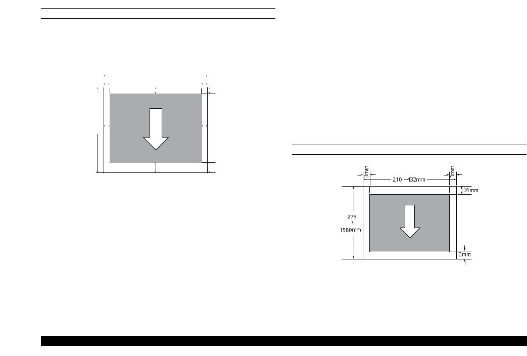
1.3.3 Printable area
ROLL PAPER
Note "*1": SC-T7000 Series "*2": SC-T5000 Series "*3": SC-T3000 Series
"*4": If “Banner” is selected for “Roll Paper Option” in the printer driver “Advanced” tab, the top and bottom margins are 0 mm.
|
|
|
|
254mm~1118mm |
|
|
|
|
|
|
||
|
|
|
|
254mm~914mm |
|
|
|
|
|
|
|
|
|
|
|
3mm/15mm |
254mm~620mm |
0mm/3mm |
|
|
|
|
|
||
|
|
|
|
|
|
|
|
|
|
|
|
|
|
|
|
|
|
|
|
|
|
|
|
|
|
|
|
|
|
|
C |
|
|
|
|
|
3mm/15mm |
|
|
|
|
|
|
|
|
|
|
|
|
|
|
127mm |
|
|
||
~ |
|
|
|
|
|
|
|
D |
|
15m B |
|
|||
A |
|
3~45mm |
|
|
|
Table 1-1. Roll Paper Margin
Roll Paper Margin Parameter |
Margin Values |
|
|
|
|
Normal |
A, C = 15mm* |
|
B, D = 3mm |
||
|
||
|
|
|
Top15mm/Bottom15mm |
A, C = 15mm |
|
|
||
B, D = 3mm |
||
|
||
|
|
|
|
A = 35mm |
|
|
|
|
Top35mm/Bottom15mm |
C =15mm |
|
|
|
|
|
B, D =3mm |
|
|
|
Table 1-1. Roll Paper Margin
Roll Paper Margin Parameter |
Margin Values |
|
|
|
A = 45mm |
|
|
Top45mm/Bottom15mm |
C =15mm |
|
|
|
B, D = 3mm |
|
|
3mm |
A, B, C, D = 3mm |
|
|
15mm |
A, B, C, D = 15mm |
|
|
When “Normal” is selected, the value for A is 20 mm for the following paper.
Premium Glossy Photo Paper (250) / Premium Semigloss Photo Paper (250) / Premium Luster Photo Paper (260) / Premium Semimatte Photo Paper (260)
When the following media are used in the “CAD / Line Drawing” mode, the value for A and C is 3 mm.
Singleweight Matte Paper
CUT SHEET
PRODUCT DESCRIPTION |
Printing Specifications |
22 |
SE Group Confidential (Related Staff Only)
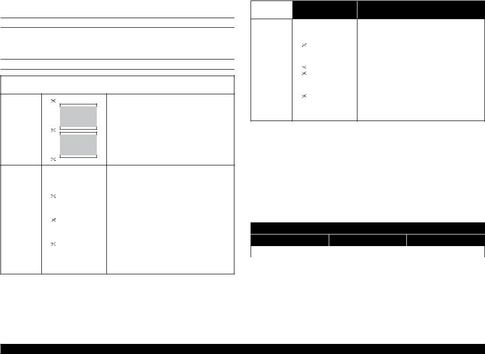
SC-T7000 series/SC-T5000 series/SC-T3000 series |
Revision G |
1.3.4 Borderless Printing Specification
AVAILABLE PAPER TYPE
For the paper types and sizes that support the borderless printing, see "1.3.2.1 Epson Special Media Table" (p17).
ROLL PAPER CUTTING OPERATION
Printer driver |
Cutting Operation |
Explanation |
|
settings |
|||
|
|
||
|
|
|
|
A |
Borderless |
The default printer driver setting is “Borderless”. |
B
The top area may become slightly uneven depending on the image since the print
|
|
operation stops while cutting the top edge of |
|
|
the roll paper. |
|
|
|
|
|
If the cut position is misaligned slightly, small |
|
A |
|
|
parts of the image may be shown on the top or |
|
Single Cut |
|
bottom of the adjacent pages. If this occurs, |
|
perform “Adjust Cut Position”. |
|
|
|
|
|
B |
When printing only one page the operation |
|
|
performed is the same as that for “Double Cut”. |
|
|
When continuously printing multiple sheets, |
|
|
|
|
|
the printer cuts 1 mm inside on the top edge of |
|
|
the first page and the bottom edge of the |
|
|
subsequent pages to avoid showing margins. |
Printer driver |
Cutting Operation |
Explanation |
|
settings |
|||
|
|
||
|
|
|
The top area may become slightly uneven depending on the image since the print
|
|
operation stops while cutting the top edge of |
|
|
the roll paper. |
|
|
|
|
A |
The printed paper is approximately 2 mm |
Double Cut |
|
shorter than the specified size since the printer |
|
cuts the paper inside the image to avoid |
|
|
||
|
|
showing top and bottom margins. |
|
B |
|
|
After cutting the bottom edge of the previous |
|
|
|
page, the printer feeds the paper, and then cuts |
|
|
the top edge of the following page. Although |
|
|
|
|
|
|
|
|
this produces 60 to 127 mm cut-off pieces, the |
|
|
cut is more accurate. |
1.3.5 Stacker
Table 1-2. Continuous Stacker
|
|
|
|
Stackable Pages |
|
|
|
Paper size |
Paper Type |
SC-T3000 |
SC-T5000 |
SC-T7000 |
|
|
||||||
|
|
|
Series |
Series |
Series |
|
|
|
|
|
|
|
|
A1 |
594 x 841mm |
Plain paper |
20 pages |
20 pages |
20 pages |
|
|
|
|
|
|
||
A0 |
841 x 1,189mm |
--- |
20 pages |
20 pages |
||
|
||||||
|
|
|
|
|
|
Table 1-3. Single Sheet Stacker
Maximum Length
SC-T3000 Series |
SC-T5000 Series |
SC-T7000 Series |
|
|
|
Approx. 1,292 mm |
Approx. 1,292 mm |
Approx. 1,575 mm |
|
|
|
PRODUCT DESCRIPTION |
Printing Specifications |
23 |
SE Group Confidential (Related Staff Only)
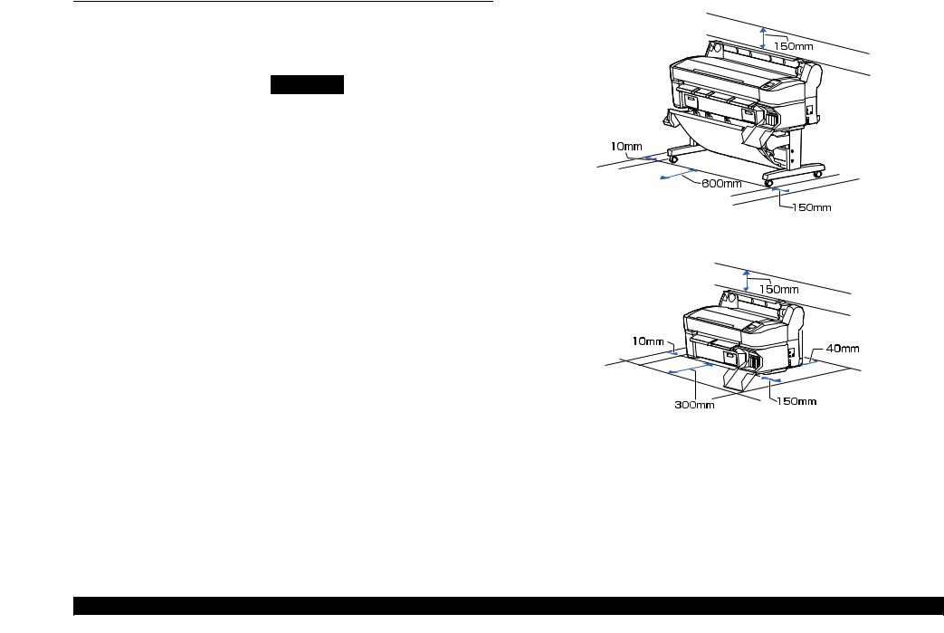
SC-T7000 series/SC-T5000 series/SC-T3000 series |
Revision G |
1.4 Hardware Specifications
This section provides the printer dimensions and shows the main components.
1.4.1 Dimensions and Weight
Model |
Width |
Depth*1 |
Height |
Weight*2 |
|
SC-T7000 Series |
1,608 mm |
813 mm |
1,128 mm |
Approx. 82 kg |
|
|
|
|
|
|
|
SC-T5000 Series |
1,405 mm |
813 mm |
1,128 mm |
Approx. 75 kg |
|
|
|
|
|
|
|
SC-T3000 Series |
1,050 mm |
691 mm |
613 mm |
Approx. 51 kg |
|
(w/o dedicated stand) |
|||||
|
|
|
|
||
|
|
|
|
|
|
SC-T3000 Series |
1,050 mm |
813 mm |
1,128 mm |
Approx. 61 kg |
|
(w/ dedicated stand) |
|||||
|
|
|
|
||
|
|
|
|
|
|
Note 1: When the paper basket is retracted |
|
|
|
||
2: Excluding ink cartridges |
|
|
|
||
1.4.2 Installation Room Requirement
Figure 1-1. SC-T7000 Series/SC-T5000 Series
Figure 1-2. SC-T3000 Series
PRODUCT DESCRIPTION |
Hardware Specifications |
24 |
SE Group Confidential (Related Staff Only)

SC-T7000 series/SC-T5000 series/SC-T3000 series |
|
Revision G |
|
1.4.3 Part Names |
|
Table 1-4. Front Side |
|
FRONT SIDE |
No. |
Name |
|
1 |
Printer cover |
||
|
|||
|
2 |
Poster board support |
|
|
3 |
Maintenance box covers |
|
|
4 |
Paper basket |
|
|
5 |
Casters |
|
|
6 |
Stack guides |
|
|
7 |
Stack guide switch lever |
|
|
8 |
Cartridge cover |
|
|
9 |
Ink cartridges |
|
|
10 |
AC inlet |
|
|
11 |
Option port |
|
|
12 |
LAN port |
|
|
13 |
Data light |
|
|
14 |
Status light |
|
|
15 |
USB port |
|
|
16 |
Control panel |
|
|
17 |
Alert lamp |
|
|
18 |
Roll rest |
|
|
19 |
Adapter guides |
|
|
20 |
Roll lock lever |
|
|
21 |
Adapter holder |
|
|
22 |
Paper slot |
|
Figure 1-3. Front Side |
23 |
Print head |
|
|
24 |
Roll paper cover |
|
|
25 |
Paper eject guide |
PRODUCT DESCRIPTION |
Hardware Specifications |
25 |
SE Group Confidential (Related Staff Only)
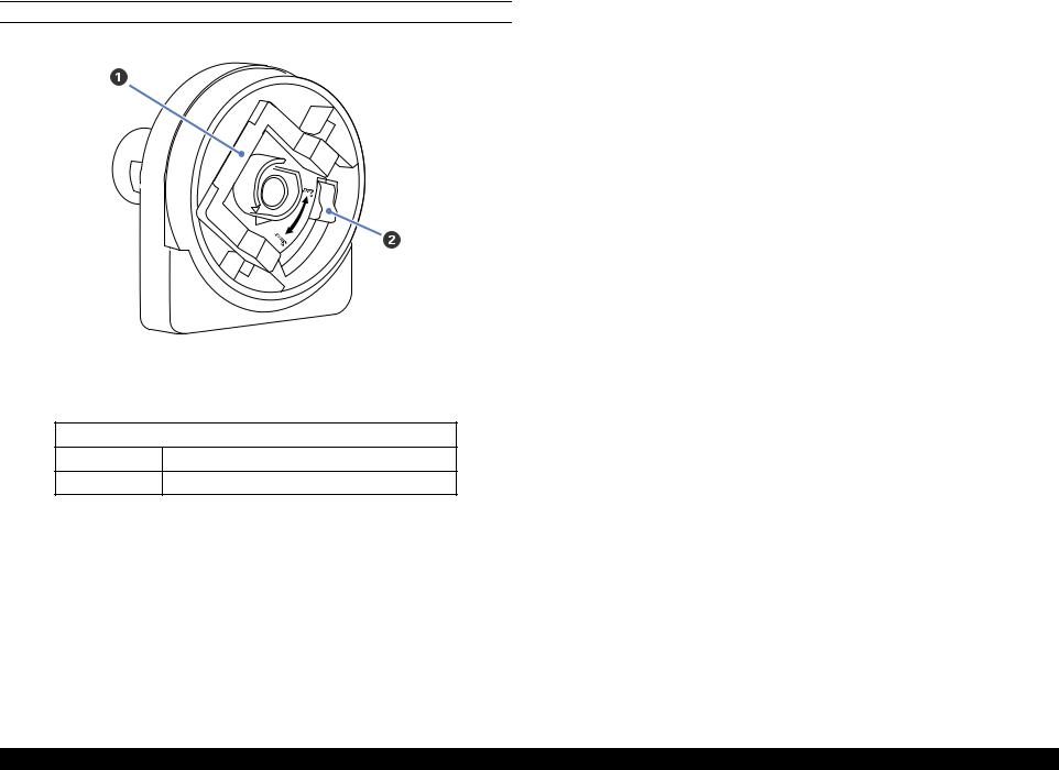
SC-T7000 series/SC-T5000 series/SC-T3000 series |
Revision G |
ROLL PAPER ADAPTER
Figure 1-4. Roll paper adapter
Table 1-5. Roll paper adapter
No. |
Name |
|
|
1Adapter lock lever
2Size lever
PRODUCT DESCRIPTION |
Hardware Specifications |
26 |
SE Group Confidential (Related Staff Only)
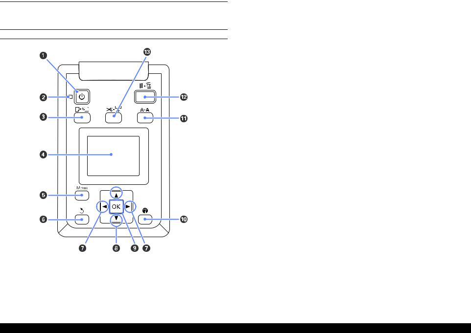
SC-T7000 series/SC-T5000 series/SC-T3000 series |
Revision G |
1.5 Control Panel Specifications
1.5.1 Control panel and LCD
CONTROL PANEL
Figure 1-5. Control panel
|
Table 1-6. Control panel |
||
|
|
|
|
|
Name |
Function |
|
|
|
|
|
1 |
Power button |
Turns the power on and off. |
|
|
|
|
|
|
|
On: The power is on. |
|
2 |
Power light |
Flashing: The printer is receiving data or cleaning the |
|
print head or performing other operations in |
|||
|
|
the course of being shut down. |
|
|
|
Off: The power is off. |
|
|
|
|
|
3 |
Load/Remove Paper button |
Displays the Load/Remove Paper menu. |
|
|
|
|
|
4 |
Screen |
Displays the printer’s status, menus, error messages, and |
|
so on. |
|||
|
|
||
|
|
|
|
5 |
[Menu] button |
Displays the menu for the tab currently selected in the |
|
display. |
|||
|
|
||
|
|
|
|
6 |
Back button |
If menus are displayed, pressing this button takes you up |
|
one level in the menu hierarchy. |
|||
|
|
||
|
|
|
|
7 |
Left/Right buttons |
Use these buttons to select tabs. |
|
|
|
|
|
8 |
Up/Down buttons |
When menus are displayed, these buttons can be used to |
|
highlight items or options. |
|||
|
|
||
|
|
|
|
|
|
Displays the menu for the tab currently selected in the |
|
|
|
display. |
|
9 |
OK button |
When menus are displayed and an item is highlighted, |
|
pressing this button displays the sub-menu for the |
|||
|
|
highlighted item. |
|
|
|
If pressed while a parameter is selected from the Menu, |
|
|
|
the parameter is set or executed. |
|
|
|
|
|
10 |
Help button |
Displays the Help menu. |
|
|
|
|
|
11 |
Maintenance button |
Displays the Maintenance menu, which is used for nozzle |
|
checks and head cleaning. |
|||
|
|
||
|
|
|
|
|
|
The printer enters pause status if this is pressed while |
|
12 |
Pause/Cancel button |
printing. |
|
Pressing this button while a menu or help is displayed |
|||
|
|
closes the menu or help and returns the printer to ready |
|
|
|
status. |
|
|
|
|
|
|
|
It is used to manually cut roll paper using the built-in |
|
13 |
Feed/Cut Media button |
cutter. |
|
If printing is not currently in progress and the printer is |
|||
|
|
loaded with roll paper, you can feed paper ahead by |
|
|
|
pressing first this button and then the [] button. |
|
|
|
|
|
PRODUCT DESCRIPTION |
Control Panel Specifications |
27 |
SE Group Confidential (Related Staff Only)
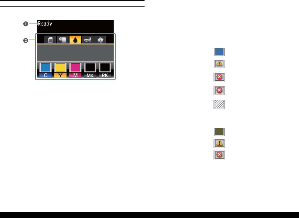
SC-T7000 series/SC-T5000 series/SC-T3000 series |
Revision G |
LCD
Screen View
|
|
Figure 1-6. LCD |
|
|
|
Table 1-7. LCD |
|
|
|
|
|
|
Name |
Function |
|
|
|
|
|
1 |
Message |
Displays the printer’s status, operation, and error |
|
messages. |
|||
|
|
||
|
|
|
|
|
|
|
|
|
|
|
|
|
|
|
|
|
|
: An error occurred. |
|
|
|
: Non-genuine cartridge is installed. |
|
|
|
|
|
|
|
Shows the status of the Maintenance Box and is used to |
|
|
|
display the Maintenance menu. |
|
|
|
Maintenance Box status is shown as follows. |
|
|
Maintenance |
: No error. |
|
|
|
|
|
|
Tab |
: The Maintenance Box is nearing the end of |
|
|
|
|
|
|
|
its service life. |
|
|
|
: Maintenance Box is at the end of its service |
|
|
|
life. |
|
|
|
|
|
|
Setup Tab |
Displays the IP address and menus for various settings. |
|
|
|
|
|
|
Enlarged |
Displayed only when a scanner is connected. |
|
|
Copy Tab |
|
|
|
|
Table 1-7. LCD |
|
Name |
|
Function |
|
|
Displays print job status and can be used to access the |
|
|
|
Queues Tab |
Print Queues menu. |
|
|
Paper Tab |
Shows the type of paper in the printer and can be used to |
|
|
|
access the Paper menu. |
|
|
|
Displays ink status. |
|
|
|
The ink cartridge status is indicated as follows. |
|
|
|
: No error. |
|
|
|
: Ink is low. |
|
|
Ink Tab |
: Ink cartridge is expended. |
2 |
Tabs/Info |
|
|
|
Display Area |
|
|
PRODUCT DESCRIPTION |
Control Panel Specifications |
28 |
SE Group Confidential (Related Staff Only)

SC-T7000 series/SC-T5000 series/SC-T3000 series Revision G
1.5.2 Menu Descriptions
Note "*1": Displayed only when optional hard disk unit is installed.
|
|
|
Table 1-8. Menu List |
|
|
|
|
|
|
|
|
Menu |
Menu Item / Setting Value (Shaded one is the default) |
|
Explanation |
||
|
|
|
|
|
|
|
|
|
|
|
Lists the estimated start time and time needed to print the selected job. |
|
|
|
|
Waiting Job Name |
It also predicts whether the job can be completed without replacing paper, ink or the |
|
|
|
|
Maintenance Box. Printing can proceed even if “Can Not Complete” is displayed. |
|
|
|
|
|
User |
|
|
|
|
|
However, the printer may run out of ink or paper during printing. |
|
|
|
|
|
Estimated Start |
|
|
|
XXXXXXXXXXX |
|
Remote Manager and the LFP HDD Utility display the reason for the “Can Not |
|
|
Print Queue*1 |
|
Time |
||
|
|
Complete” message and allow you to hold or cancel the job. |
|||
|
(name of queued print job) |
Estimated Print |
|||
|
|
The printer will only predict availability on the basis of the amount of paper |
|||
|
|
|
|
Time |
|
|
|
|
|
remaining if “On” is selected for “Roll Paper Remaining”. |
|
|
|
|
|
Printing |
|
|
|
|
|
The printer will not predict availability on the basis of the amount of ink remaining |
|
|
|
|
|
Availability |
|
|
|
|
|
when documents are printed using LFP Print Plug-In for Office or EPSON |
|
|
|
|
|
|
|
|
|
|
|
|
CopyFactory5. |
|
|
|
|
|
|
|
|
|
|
Paused Job Name |
This option is available only if “On” is selected for “Store Held Job” in the Setup |
|
|
|
|
menu. |
|
|
|
|
XXXXXXXXXXX |
User |
Displays the print settings for held jobs and the reason the job is held. |
|
|
|
Paper Type |
Jobs that are held because the job print settings differ from those currently selected |
|
|
|
View Hold Queue |
(name of held print |
||
|
Hold Queue*1 |
Source |
for the printer can be printed as described below. |
||
Print Queues menu |
|
job) |
|||
|
|
Size |
1. Replace the paper and take whatever other steps may be necessary to ready the |
||
|
|
|
|||
|
|
|
|
||
|
|
|
|
Reason For Hold |
device for printing. |
|
|
|
|
2. Select “Resume All Jobs”. |
|
|
|
|
|
|
|
|
|
|
|
|
|
|
|
Resume All Jobs |
|
Press the [OK] button to resume all held jobs currently in the queue. |
|
|
|
|
|
|
|
|
|
|
|
Stored Job Name |
|
|
|
|
|
User |
|
|
|
|
|
Length |
|
|
|
|
|
Pages |
Shows the status of the selected stored job when it was last printed. |
|
Saved Job Queue*1 |
XXXXXXXXXXX (name of stored print |
Paper Type |
After viewing the job, press the [OK] button to enter the number of copies. Press the |
|
|
|
job) |
|
Copies |
[]/[] buttons to choose the number of copies and press the [OK] button to display |
|
|
|
|
Source |
the estimated print time and print availability. Press the [OK] button to start printing. |
|
|
|
|
|
|
|
|
|
|
Size |
|
|
|
|
|
Estimated Print |
|
|
|
|
|
Time |
|
|
|
|
|
|
|
|
Print Job Log Sheet |
|
|
Press the [OK] button to print the print job log. |
|
|
|
|
|
|
|
PRODUCT DESCRIPTION |
Control Panel Specifications |
29 |
SE Group Confidential (Related Staff Only)

SC-T7000 series/SC-T5000 series/SC-T3000 series |
|
|
Revision G |
|||
|
|
|
|
Table 1-8. Menu List |
|
|
|
|
|
|
|
|
|
Menu |
Menu Item / Setting Value (Shaded one is the default) |
|
|
Explanation |
||
|
|
|
|
|
|
|
|
|
|
|
|
|
Press the [OK] button to view instructions for removing the paper. Follow the on- |
|
|
|
|
|
Remove Paper |
screen instructions to remove the paper. |
|
|
|
|
|
|
Instructions are not displayed if no paper is loaded. |
|
|
|
|
|
|
|
|
Load/Remove Paper |
|
|
|
Roll Paper |
Highlight the paper to be loaded and press the [OK] button. Follow the on-screen |
|
|
|
|
|
Cut Sheet (up to 0.8 |
instructions to load the paper. |
|
|
|
|
|
mm thick) |
If paper is already loaded in the printer, the instructions for removing the loaded |
|
|
|
|
|
|
paper type will be displayed before loading instructions are shown. |
|
|
|
|
|
Poster Board |
|
|
|
|
|
|
|
|
|
|
|
|
|
|
|
|
|
Photo Paper |
|
|
|
|
|
|
|
|
|
|
|
|
|
Matte Paper |
|
Select the type of paper loaded. |
||
|
Select Paper Type |
|
|
|
||
|
Plain Paper |
|
||||
|
|
|
|
|||
|
|
|
|
|
|
|
|
|
Others |
|
|
|
|
|
|
|
|
|
||
Paper menu |
|
Custom Paper |
|
Select the name of the custom paper loaded in the printer. |
||
|
|
|
|
|
|
|
|
|
|
|
|
Photo Paper |
|
|
|
|
|
|
|
|
|
|
|
Select Reference |
|
Matte Paper |
You can select the media type that is the closest to the paper you are using. |
|
|
|
|
|
||
|
|
|
|
Plain Paper |
||
|
|
|
Paper |
|
|
|
|
|
|
|
|
|
|
|
|
|
|
|
Others |
|
|
|
|
|
|
|
|
|
Custom Paper |
XXXXXXXXXXX |
|
|
No Paper Selected |
Select this option if you do not wish to specify the paper type. |
|
|
|
|
|
||
|
(name of custom |
|
|
Narrow |
|
|
|
Setting |
|
|
Select the platen gap which is the distance between the print head and the paper. |
||
|
paper type) |
|
|
|
||
|
|
|
|
Standard |
||
|
|
|
Platen Gap |
|
Normally, select “Standard”. Select a wider setting if printed images are smeared. If, |
|
|
|
|
|
Wide |
upon performing head alignment you feel that it is still not completely aligned, select |
|
|
|
|
|
|
||
|
|
|
|
|
|
“Narrow”. |
|
|
|
|
|
Wider |
|
|
|
|
|
|
|
|
|
|
|
|
|
|
|
|
|
|
Detect Paper |
|
Press the [OK] button to print a pattern to determine the thickness of the current paper. |
|
|
|
|
Thickness |
|
Select the pattern number with the least misalignment from the print results. |
|
|
|
|
|
|
|
|
PRODUCT DESCRIPTION |
Control Panel Specifications |
30 |
SE Group Confidential (Related Staff Only)
Loading...