

Page 1
®
6(59,&( 0$18$/
6(59,&( 0$18$/
6(59,&( 0$18$/6(59,&( 0$18$/
Color Inkjet Printer
EPSON Stylus Photo 1200
SEIJ98007
Page 2

Notice
†
All rights reserved. No p art of t his manual may be reprod uced, stored i n a ret rieval syste m, or trans mit ted in any form or by any means electronic,
mechanical, photocopying, or otherwise, without the prior written permission of SEIKO EPSON CORPORATION.
†
All effort have been made to ensure the accuracy of the contents of this manual. However, should any errors be detected, SEIKO EPSON would
greatly appreciate being informed of them.
†
The contents of this manual are subject to change without notice.
†
All effort have been made to ensure the accuracy of the contents of this manual. However, should any errors be detected, SEIKO EPSON would
greatly appreciate being informed of them.
†
The above not withstanding SEIKO EPSON CORPORATION can assume no responsibility for any errors in this manual or the consequences
thereof.
EPSON is a registered trademark of SEIKO EPSON CORPORATION.
General Notice: Other product names used herein are for identification purpose only and may be trademarks or registered trademarks of their
respective owners. EPSON disclaims any and all rights in those marks.
Copyright © 1998 SEIKO EPSON CORPORA TION. Printed in Japan.
Page 3

PRECAUTIONS
Precautionary notations throughout the text are categorized relative to 1)Personal injury and 2) damage to equipment.
DANGER
WARNING
The precautionary measures itemized below should always be observed when performing repair/maintenance procedures.
Signals a precaution which, if ignored, could result in serious or fatal personal injury. Great cauti on should be exercised in
performing procedures preceded by DANGER Headings.
Signals a precaution which, if ignored, could result in damage to equipment.
DANGER
1. ALWAYS DISCONNECT THE PRODUCT FROM THE POWER SOURCE AND PERIPHERAL DEVICES PERFORMING ANY
MAINTENANCE OR REPAIR PROCEDURES.
2. NO WORK SHOULD BE PERFORMED ON THE UNIT BY PERSONS UNFAMILIAR WITH BASIC SAFETY MEASURES AS DICTATED
FOR ALL ELECTRONICS TECHNICIANS IN THEIR LINE OF WORK.
3. WHEN PERFORMING TESTING AS DICTATED WITHIN THIS MANUAL, DO NOT CONNECT THE UNIT TO A POWER SOURCE UNTIL
INSTRUCTED TO DO SO. WHEN THE POWER SUPPLY CABLE MUST BE CONNECTED, USE EXTREME CAUTION IN WORKING ON
POWER SUPPLY AND OTHER ELECTRONIC COMPONENTS.
WARNING
1. REPAIRS ON EPSON PRODUCT SHOULD BE PERFORMED ONLY BY AN EPSON CERTIFIED REPAIR TECHNICIAN.
2. MAKE CERTAIN THAT THE SOURCE VOLTAGES IS THE SAME AS THE RATED VOLTAGE, LISTED ON THE SERIAL NUMBER/
RATING PLATE. IF THE EPSON PRODUCT HAS A PRIMARY AC RATING DIFFERENT FROM AVAILABLE POWER SOURCE, DO NOT
CONNECT IT TO THE POWER SOURCE.
3. ALWAYS VERIFY THAT THE EPSON PRODUCT HAS BEEN DISCONNECTED FROM THE POWER SOURCE BEFORE REMOVING OR
REPLACING PRINTED CIRCUIT BOARDS AND/OR INDIVIDUAL CHIPS.
4. IN ORDER TO PROTECT SENSITIVE MICROPROCESSORS AND CIRCUITRY, USE STATIC DISCHARGE EQUIPMENT, SUCH AS
ANTI-STATIC WRIST STRAPS, WHEN ACCESSING INTERNAL COMPONENTS.
5. REPLACE MALFUNCTIONING COMPONENTS ONLY WITH THOSE COMPONENTS BY THE MANUFACTURE; INTRODUCTION OF
SECOND-SOURCE ICs OR OTHER NONAPPROVED COMPONENTS MAY DAMAGE THE PRODUCT AND VOID ANY APPLICABLE
EPSON WARRANTY.
Page 4
About This Manual
This manual describes basic functions, theory of electrical and mechanical operations, maintenance and repair procedures of EPSON Stylus Photo
1200. The instructions and procedures included herein are intended for the experienced repair technicians, and attention should be given to the
precautions on the preceding page.
Contents
This manual consists of six chapters and Appendix.
CHAPTER 1. PRODUCT DESCRIPTIONS
Provides a general overview and specifications of the
product.
CHAPTER 2. OPERATING PRINCIPLES
Describes the theory of electrical and mechanical
operations of the product.
CHAPTER 3. TROUBLESHOOTING
Provides the step-by-step procedures for the
troubleshooting.
CHAPTER 4. DISASSEMBLY AND ASSEMBLY
Describes the step-by-step procedures for
disassembling and assembling the product.
CHAPTER 5. ADJUSTMENTS
Provides Epson-approved methods for adjustment.
CHAPTER 6. MAINTENANCE
Provides preventive maintenance procedures and the
lists of Epson-approved lubricants and adhesives
required for servicing the product.
APPENDIX
Provides the following additional information for
reference:
• Connector pin assignments
• Electric circuit boards components layout
• Exploded diagram
• Electrical circuit boards schematics
Symbols Used in This Manual
Various symbols are used throughout this manual either to provide
additional information on a specif ic topic or to warn of possible danger
present during a procedure or an action. Be aware of all symbols when
they are used, and always read WARNING, CAUTION or NOTE
messages.
Indicates an operating or maintenance procedure, practice
or condition that, if not strictly observed, coul d result in in jury
or loss of life.
CAUTION
CHECK
PO INT
Indicates an operating or maintenance procedure, practice,
or condition that, if not strictly observed, could result in
damage to, or destruction of, equipment.
May indicate an operating or maintenance procedure,
practice or condition that is necessary to accomplish a task
efficiently. It may also provide additional information that is
related to a specific subject, or comment on the results
achieved through a previous action.
Page 5
Revision Status
Revision Issued Date Description
Rev. A January 11, 1999 First release
Page 6

EPSON Stylus Photo 1200 Revision A
Table of Contents
Product Description
Overview................ ....... ...... ...... ....... ...... ....... ...... ....... ..................................... 8
General Characteristics............................................................................. 8
Basic Specification .............................................................................. ...... ..... 8
Interface........................................................................................................ 11
Operation Specification ...................................... ....... ................................... 11
Major Components ....................................................................................... 12
Consumables................................................................................................ 12
Operating Principles
Overview....................................................................................................... 14
Troubleshooting
Disassembly and Assembly
Adjustment
Overview....................................................................................................... 20
Adjustments............................................................................................. 20
Adjustment Program................. ....... ...... ....... ...... .......................................... 21
Activatioin of Program ............................................................................. 21
Maintenance
Appendix
Exploded Diagram........................................................................................ 26
Circuit Boards............................................................................................... 32
6
Page 7

PRODUCT DESCRIPTION
&+$37(5
4
Page 8

EPSON Stylus Photo 1200 Revision A
1.1 Overview
Stylus Photo 1200 is 127 digits color ink jet printer whose function and
characteristics are based on Stylus Photo 750. Theref ore, since only
revised points for Stylus Photo 1200 are explained in thi s manual, refer
to the Service Manual of Stylus Photo 750 for the rest of infor m ation.
1.1.1 General Characteristics
† High Color Print Quality
„ 1440(H) x 720(V) dpi printing
„ 6-Color printing(YMCKcm)
„ Traditional and New Microweave
† Built-in auto sheet feeder
„ Holds 100 cut-sheets (64 g/m
„ Holds 10 envelopes
„ Holds 30 transparency films
† Built-in 3 I/F
„ Mac. serial I/F (up to approx. 1800kbps)
„ Bi-directional parallel I/F(IEEE-1284 level 1 device)
„ USB
2
)
1.2 Basic Specification
PAPER SPECIFICATION
† Paper Size
„ Cut Sheet
A3 (297mm x 420mm)
B (279mm x 432mm)
B4 (257mm x 364mm)
„ Envelope
220 x 132 (220mm x 132mm)
„ EPSON Special Media (Photo Quality Ink Jet Paper, 360 d pi Ink
Jet Paper, Photo Qualtiy Glossy Film, Photo Paper)
A3+ (329mm x 483mm)
B (279mm x 432mm)
B4 (257mm x 364mm)
NOTE: Other paper specification is same as EPSON Stylus Photo
750.
CHARACTER TABLES
† 2 international character sets
PC 437 (US, Standard Europe)
PC 850 (Multilingual)
† Win dows/Macintosh exclusive
TYPE FACE
† Bit map LQ font: EPSON Courier 10 CPI
Product Description Overview 8
Page 9
EPSON Stylus Photo 1200 Revision A
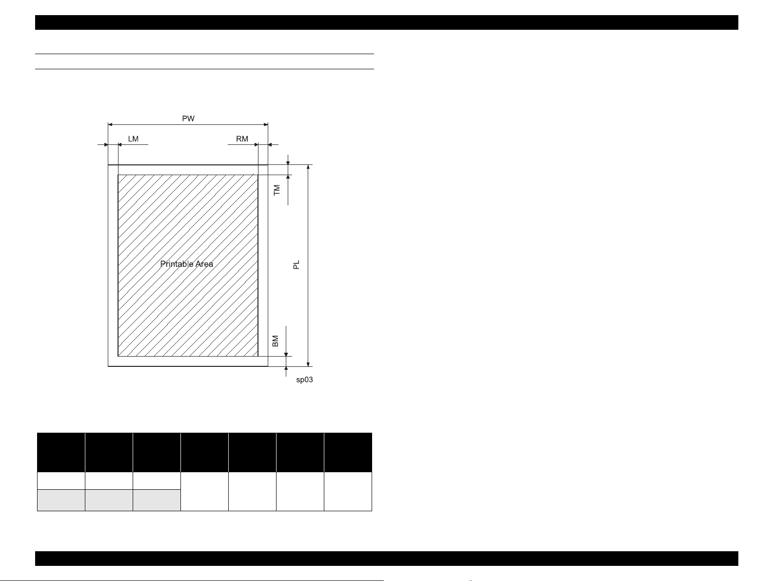
PRINTABLE AREA
Printable area is as follows.
Figure 1-1. Printable Area
Table 1-1. Printable Area(mm)
Paper
Size
A3+ 329 483
A3 297 420
Paper
Width
(PW)
Paper
Length
(PL)
Left
Margin
(LM)
More than 3More than 3More than
Right
Margin
(RM)
Top
Margin
(TM)
3
Bottom
Margin
(BM)
14 or
more than
3
Product Description Basic Specification 9
Page 10
EPSON Stylus Photo 1200 Revision A
INK
† Color Ink Cartridge
„ Type: Exclusive cartridge
„ Color: Magenta, Cyan, Yellow, Light Ma, Light Cyan
„ Print Capacity:330 pages/A4 (360 dpi, 5% duty each color)
„ Ink life: 2 years from production date
„ Storage Temperature
- 20
°C ∼ 40 °C (Storage, within a month at 40 °C)
°C ∼ 40 °C (Packing storage, within a month at 40 °C)
- 30
°C ∼ 60 °C (Transit, within 120 hours at 60 °C and within a
- 30
month at 40
°C)
„ Dimension: 42.9mm (W) x 52.7mm (D) x 38.5mm (H)
NOTE: Ink cartridge can not re-fill, only ink cart ridge i s prepar ed fo r
article of consumption.
Do not use the ink cartridge which was passed away the ink
life.
4
°
Ink will be frozen under -
C environment, however it wi ll be
usable after placing it more than 3 hours at room
temperature.
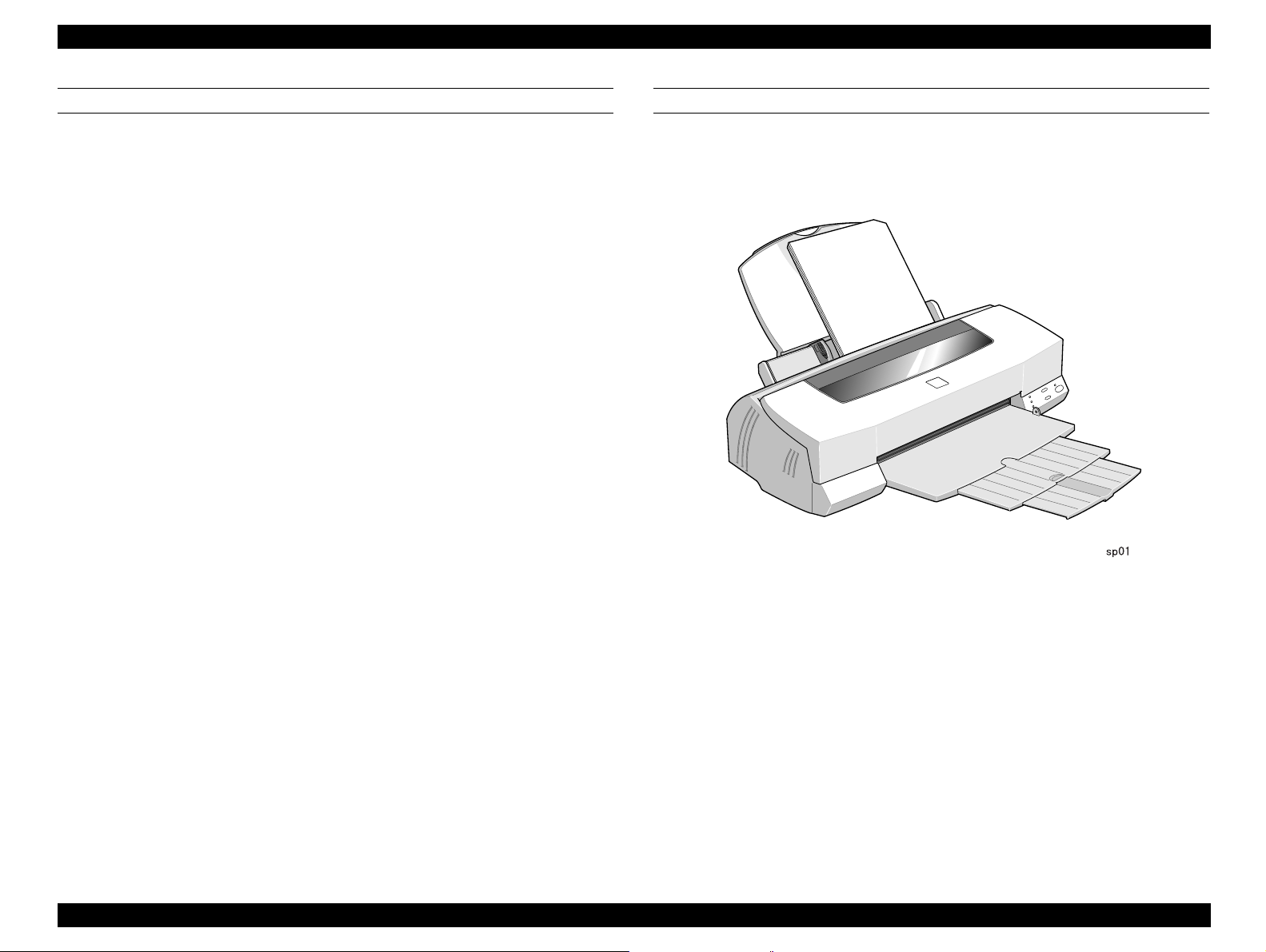
PHYSICAL SPECIFICATION
† Dime nsion: 578mm(W) x 286mm(D) x 175mm(H)
† Weight: 7 Kg
Figure 1-2. Exterior View of Stylus Photo 1200
NOTE:Specification of black ink cartridge is same as Stylus Photo
750.
Product Description Basic Specification 10
Page 11

EPSON Stylus Photo 1200 Revision A
1.3 Interface
Stylus Photo 1200 is equipped with the same interf aces as Stylus Photo
750. Therefore, refer to the Service Manual of Stylus Photo 750 for
interface specificaton.
† I EEE-1284 Nibble Mode Parallel I/F
† Ser ial I/F(RS-423)
† Universal Serial Bus Specification Revision 1.0
1.4 Operation Specification
Although the specification and function of buttons and LED lighjts are
the same as those of Stylus Photo 750, the panel layout is different. See
the figure below.
LED(Paper Out)
LED
(Black
Ink out)
LED(Color Ink Out)
Load/Eject
Cleaning
LED(Power)
sp02
Power
Figure 1-3. Control Panel
Product Description Interface 11
Page 12

EPSON Stylus Photo 1200 Revision A
1.5 Major Components
Major components which consist Stylus Photo 1200 are as follow.
† Cont rol Board: C264 Main or C259 Main Board
(Circuit and pattern are same in the both
boards, but connector shapes are different)
† Power Supply Board: C257 PSB Board (same board used in Stylus
Photo 750)
† Control Panel: C206 PNL Board (same PNL board used in
Stylus Photo EX)
† Printer Mechanism: M-4N60
1.6 Consumables
Consumable of this printer are as follow.
Table 1-2. Consumables
Code No. Name
S020187 Black ink cartridge
T001011, T001051, T001091,
T001311
NOTE:Color ink cartridge for Stylus Photo 750 can not be used for
Stylus Photo 1200.
Color ink cartridge
Product Description Major Components 12
Page 13

OPERATING PRINCIPLES
&+$37(5
5
Page 14

EPSON Stylus Photo 1200 Revision A
2.1 Overview
Comparing with Stylus Photo750, following points in Stylus Photo1200
are different from Stylus Photo 750.
† Printer Mechanism
„ Since Stylus Photo1200 can deal with A3+ size, mechanism is
extended from 80 digits to 127 digits.
„ Size of color ink cartridge is changed, since the color ink life is
improved.
† Electric Circuit
„ Circuit component of Stylus Photo1200 i s same as t hat of St ylus
Photo 750.
„ Control panel board(C206 PNL Board) is also used for Stylus
Photo EX and Stylus Color 400.
Therefore, since the printer mechanism and electric circuit of Stylus
Photo 1200 are basically same as those of Stylus Photo 750, refer to
the Service Manual of Stylus Photo 750 for more details.
Operating Principles Overview 14
Page 15

TROUBLESHOOTING
&+$37(5
6
Page 16

EPSON Stylus Photo 1200 Revision A
Since EPSON Stylus Photo 1200 is a ink jet printer based on the
function and characteristics of ESPON Stylus Photo 750, refer to the
Service Manual of EPSON Stylus Photo 750 for troubleshooting.
Troubleshooting 16
Page 17

DISASSEMBLY AND ASSEMBLY
&+$37(5
7
Page 18

EPSON Stylus Photo 1200 Revision A
Since the basic component of EPSON Stylus Photo 1200 is same as
that of EPSON Stylus Photo750, refe r to t he Servi ce Manual o f EPSON
Stylus Photo 750 for disassembly and assembly procedures.
Disassembly and Assembly 18
Page 19

ADJUSTMENT
&+$37(5
8
Page 20

EPSON Stylus Photo 1200 Revision A
Screen indicates
p rin te r m o d els to
select
S e lec t th e p rin te r
m odel nam e
Screen indicates
destinations to
select
W ritin g to
EEPROM
M odel nam e is
acquired.
Screen indicates to
perform program w ith
se le c te d p rin te r m o d el
A djustm ent program
is a c tiv a te d .
End
A c tiv a te A d ju stm e n t
P r o g r a m
No
No
Yes
Yes
5.1 Overview
This section will explain required adjustment procedures for this printer
after disassembling or replacing parts.
5.1.1 Adjustments
Since the basic components and function of this print er is same as
those of Stylus Photo 750, both printers share the same adjustment
items. Therefore, adjustment items only f or Stylus Photo 1200 are
explained here.
Priority order 1 2 3 4 5
Procedure/
Replacing parts
Printer
Mechanism
Exchange
Control Bo ard
Exchange
Print Head
Exchange
CR Motor
Exchange
Table 5-1. Required Adjustments
Paper Gap
Adjustment
-- O O --- O
-- O O O O
-- O O O ---
--- --- --- --- O
Ink
initial
charge
Head ID
Writing
Head
Angular
Adjustment
NOTE:2.Initial ink charge should be done after inst alling the new ink
cartridge.
Bi-D
Adjustment
Carriage
Assembly
Removal/
Exchange
Roller Assembly/
Removal/Exchage
NOTE:1. “O” means adjustment is required. “--- ” means a djus tment
is not required.
Adjustment Overview 20
O --- --- O O
O --- --- --- ---
Figure 5-1. Flow Chart
Page 21

EPSON Stylus Photo 1200 Revision A
5.2 Adjustment Program
Exclusive adjustment program is necessary in this section. This
interface improved user interfance and became easi er to use than the
previous programs. Comparing with the adjustment of Stylus Photo7 50,
only modified or changed points are explained here.
5.2.1 Activatioin of Program
1. Turn off both printer and host computer, and connect them with
parallel interface cable.
2. Turn on the printer and host computer.
3. Make a folder in the host computer and save the file of adjustment
program in that folder. Or , insert the disk of the adjustment program
into the disk drive.
4. Run the program on the DOS Prompt of the Windows. Th e followi ng
screnn (See Figure 5-2) will appear.
5. Select “Stylus Photo 1200” by using
Then, the screen for destination (See Figure 5-3) will appear.
↑↓ key and press “Enter” key.
Prom pt SP751200
Auto
Figure 5-2. First Screen of Adjustment Program
Prom pt SP751200
Auto
Figure 5-3. Destination Selection
Adjustment Adjustment Program 21
Page 22

EPSON Stylus Photo 1200 Revision A
6. Select “World” and press “Enter” key. The screen like figure 5-4 will
appear.
7. Select “Perform (Boot this PROGRAM). Refer to t he Service Manaul
of Stylus Photo 750 for the rest of adjustment procedures.
Prom pt S P751200
Auto
Figure 5-4. Starting the Program
Adjustment Adjustment Program 22
Page 23

MAINTENANCE
&+$37(5
9
Page 24

EPSON Stylus Photo 1200 Revision A
Since the basic component of EPSON Stylus Photo 1200 is same as
that of EPSON Stylus Photo750, refe r to t he Servi ce Manual o f EPSON
Stylus Photo 750 for maintenance.
Maintenance 24
Page 25

APPENDIX
&+$37(5
:
Page 26

EPSON Stylus Photo 1200 Revision A
7.1 Exploded Diagram
B
B
Figure 7-1. Exploded Diagram (1)
Appendix Exploded Diagram 26
Page 27

EPSON Stylus Photo 1200 Revision A
D
Figure 7-2. Exploded Diagram(2)
Appendix Exploded Diagram 27
Page 28

EPSON Stylus Photo 1200 Revision A
H
J
I
I
A
A
H
C
D
Figure 7-3. Exploded Diagram(3)
Appendix Exploded Diagram 28
Page 29

EPSON Stylus Photo 1200 Revision A
E
K
J
C
L
K
L
Figure 7-4. Exploded Diagram (4)
Appendix Exploded Diagram 29
Page 30

EPSON Stylus Photo 1200 Revision A
F
E
F
G
G
Figure 7-5. Exploded Diagram (5)
Appendix Exploded Diagram 30
Page 31

EPSON Stylus Photo 1200 Revision A
Figure 7-6. Exloded Diagram (Packing)
Appendix Exploded Diagram 31
Page 32

EPSON Stylus Photo 1200 Revision A
7.2 Circuit Boards
There are 2 kinds of main boards for this printer; C259 Main Board and
C264 Main Board. C259 Main Board and C257 PSB Power Supply
Circuit are used for Stylus Photo750. C206 PNL Control Pane l Board is
common with Stylus Color400 and Stylus Photo EX.
Therefore, refer to the corresponding Service Manual for each circuit
diagram.
CAUTION
C259 Main Board and C264 Main Board have same
circuit and pattern. However, the connector shape
with other elements is different, be careful of its
selection.
Appendix Circuit Boards 32
 Loading...