

Page 1

Chapter 6
Maintenance
6.1 OVERVIEW............................................................................................................6-1
6.1.1 Cleaning................................................................................................................................... 6-1
6.1.2 Service Maintenance..............................................................................................................6-1
6.1.3 Lubrication..............................................................................................................................6-2
Page 2
Chapter 6 Maintenance
6.1 OVERVIEW
This section describes the points and the procedures for maintaining the printer in its optimum condition.
6.1.1 Cleaning
This printer has no mechanical components requiring regular cleaning. Therefore, the points described
below are suggested to be checked for any dirt and make an appropriate cleaning if necessary.
CAUTION
Never use the chemical solvents, such as thinner, to clean the printer. These chemicals can
damage the components of the printer.
Be careful not to damage the components when you attempt to clean the inside of the printer.
Do not scratch surface of “ROLLER, ASSEMBLY, PF”.
(Use soft brush to wipe off any dusts, or use soft cloth moistened with alcohol)
Housing: Use clean soft cloth moistened with water and wipe off any dirt. If the housing
stained with an ink, use a cloth moistened with a neutral detergent to wipe it
off.
Inside the printer: Use a vacuum cleaner to remove any paper dust.
6.1.2 Service Maintenance
If the print irregularity (missing dot, white line, etc.) has occur or the printer indicates “MAINTENANCE
ERROR”, perform the following operation to clear the error.
Head Cleaning
1. The printer has a built-in head cleaning function and is executable from the control panel.
2. Confirm that the printer is in stand-by state (the POWER indicator is not blinking), and hold down the
cleaning button on the control panel for more than 3 sec.
3. The printer perform the built-in cleaning sequence. (during cleaning operation, the POWER indicator is
blinking)
Maintenance Error Clear
Since the printer consumes the ink, not only for printing but also for another operation like cleaning,
certain amount of ink are wasted. Therefore, the printer counts the amount of waste ink and they are
collected at the waste ink pad, and once the amount of waste ink reaches the predefined limit, the printer
indicates “MAINTENANCE ERROR” and the waste ink pad should be replaced as follows:
1. Replace the waste ink pad to new one.
2. After re-assemble the printer, turn the printer on while holding down the following buttons on the control
panel:
”LOAD/EJECT” button
”CLEANING” button
3. Press “LOAD/EJECT” button again while “PAPER END” indicator is blinking. This clears the
maintenance error condition and the waste ink counter value stored in EEPROM of the main board.
Rev. A
6-1
Page 3
EPSON Stylus Photo
2
6.1.3 Lubrication
The type and amount of oil and grease used on this printer are determined based on the results of internal
evaluations. Therefore, specified type and amount of oil and grease must be applied at specified part of
the printer mechanism when servicing the printer.
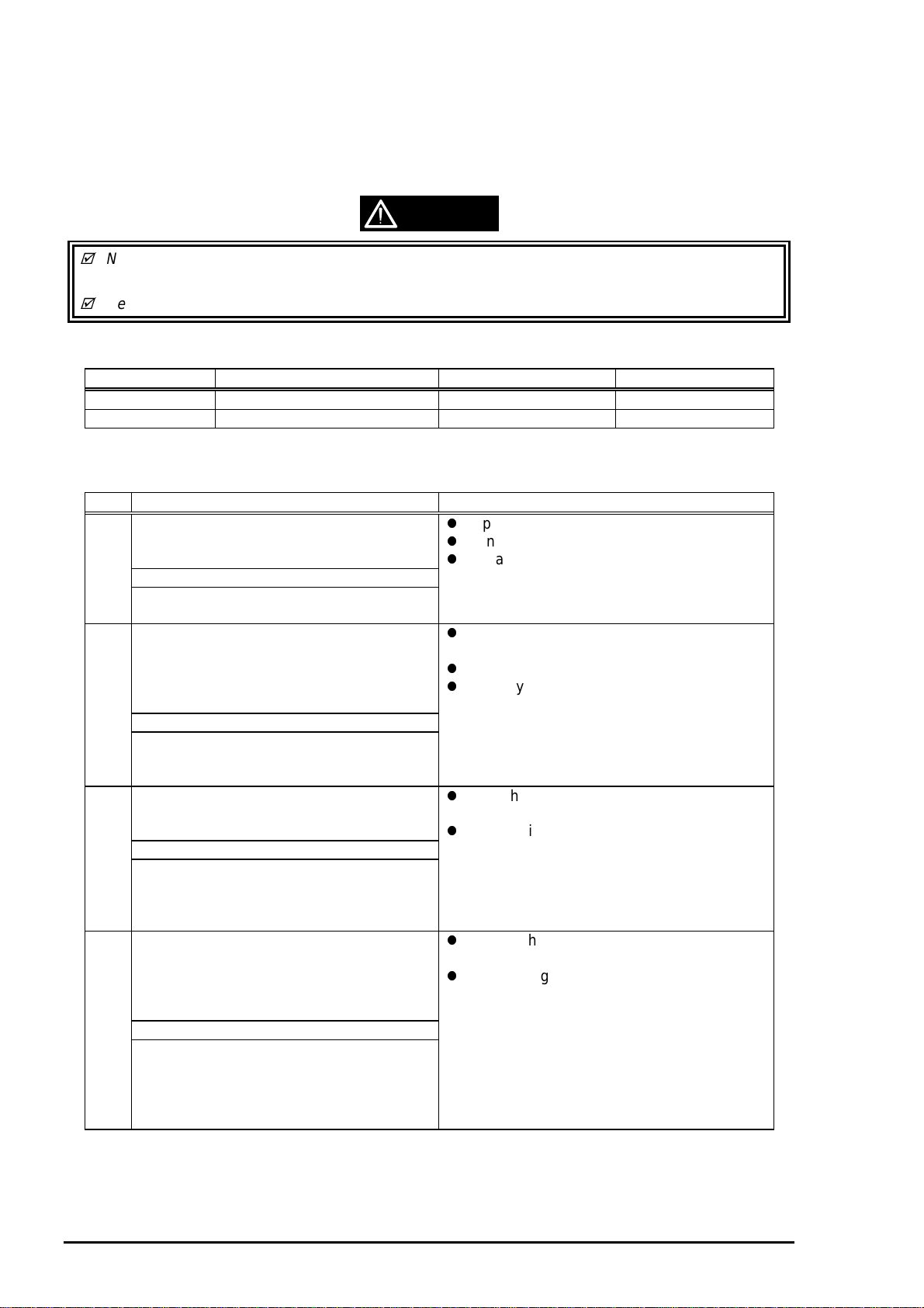
CAUTION
Never use the oil and the grease other than those specified in this manual and using different
type of lubricant can damage the printer and the components.
Never apply oil or grease exceeding the amount specified in this manual.
Table 6-1. Specified Lubricants
Type Name EPSON Code Supplier
Grease G-26 B702600001 EPSON
Oil O-8 1019753 EPSON
Table 6-2. Lubrication Points
No. Standard Remarks
1 <Lubrication Point>
Contact between “ROLLER, PF” and
“PAPER GUIDE, REAR”
<Lubricant Type> G-26
<Lubrication Amount>
A half turn of “ROLLER, PF”
2 <Lubrication Point>
“Contact between “PAPER GUIDE,
FRONT” and each rollers:
1) “ROLLER, PF” (1 point)
2) “ROLLER, EXIT” (2 points)
<Lubricant Type> G-26
<Lubrication Amount>
1) 10mm long
2) 2mm long
3 <Lubrication Point>
Contact between the carriage assembly
and “FRAME, UPPER”
<Lubricant Type> G-26
<Lubrication Amount>
From the HP sensor installation point to
the point where “GUIDE PLATE, CABLE”
is attached.
4 <Lubrication Point>
Gears:
1) “GEAR, 67.2”
2) “COMBINATION GEAR, 8, 14.4”
3) “GEAR, 23.2”
<Lubricant Type> G-26
<Lubrication Amount>
1) 1/4 of gear tooth
2) 1/3 of gear tooth
3) 1/3 of gear tooth
4) 1/3 of gear tooth
Apply grease while rotating “GEAR, 67.2”.
Do not put grease around the paper path.
Use a syringe to apply it.
Apply to the contact of a hook of “PAPER
GUIDE, FRONT” and each roller.
Do not put grease around the paper path.
Use a syringe to apply it.
Verify that the carriage moves smoothly
after lubricating it.
Use a syringe to apply it.
Rotating the gears after applying grease to
evenly distribute it.
Use a syringe to apply it.
6-
Rev. A
Page 4

Chapter 6 Maintenance
3
Table 6-3. Lubrication Points (Continued)
No. Standard Remarks
5 <Lubrication Point>
The shaft for “GEAR, 16, 40.8” at
“FRAME, LEFT”
<Lubricant Type> G-26
<Lubrication Amount>
Approx. 5mm long
Use a syringe to apply it.
6 <Lubrication Point>
Bush for “ROLER, PF”
1) Left: Inside the bush
2) Right: Inside the bush (near the
pump assembly)
<Lubricant Type> G-26
<Lubrication Amount>
Approx. 3mm diametrically
7 <Lubrication Point>
Both Left/Right Bush for “ROLLER, EXIT”
<Lubricant Type> G-26
<Lubrication Amount>
Evenly apply inside the bush
8 <Lubrication Point>
Contact between “HOLDER, PULLEY,
DRIVEN” and “FRAME, UPPER”
<Lubricant Type> G-26
<Lubrication Amount>
2mm long at each specified point
When applying to the right bush, apply it
from the side of the paper path and wipe off
any grease stick out to the cap assembly
side.
Rotate “ROLLER, PF” after applying the
grease to evenly distribute it in the bush.
Use a syringe to apply it.
Do not put grease around the paper path.
Use a syringe to apply it.
Verify that the holder slides only with a
spring force after applying the grease.
Use a syringe to apply it.
9 <Lubrication Point>
ASF;
A round hole of the right frame of ASF (to
hold the roller shaft)
<Lubricant Type> G-26
<Lubrication Amount>
Evenly apply inside the hole
10 <Lubrication Point>
ASF;
Contact between “HOPPER” and “LEVER,
HOPPER, RELEASE”
<Lubricant Type> G-26
<Lubrication Amount>
Evenly apply to the contact
Do not put grease to “ROLLER,
ASSEMBLY, LD”.
Completely wipe off any grease stack out to
inner side of ASF.
Rev. A
6-
Page 5

EPSON Stylus Photo
4
Table 6-4. Lubrication Points (Continued)
No. Standard Remarks
11 <Lubrication Point>
A round hole of the left frame of ASF
(“GEAR, 34” is inserting to this hole)
<Lubricant Type> G-26
<Lubrication Amount>
Evenly apply inside the hole
Completely wipe off any grease stack out to
inner side of ASF.
12 <Lubrication Point>
Oil pad of carriage assembly
<Lubricant Type> O-8
<Lubrication Amount>
0.6cc
Note that This is an amount to be applied
new oil pad when replacing it.
This application must be made only when;
*Replacing the carriage assembly
*Replacing oil pad
Use a precise syringe to apply it. If
accidentally apply too much oil to oil pad,
thrown it away and take a new oil pad again.
Leave oil pad for a while to wait until oil is
evenly infiltrate and install it on the carriage
assembly.
WARNING
Never apply oil to the CR guide shaft directly or additionally to the oil pad. This may
cause fatal damage to the components of the printer.
*Never apply the oil exceeding 0.6cc.
No.12
(Oil pad)
Carriage Assembly
(bottom view)
"SHAFT, CR, GUIDE"
6-
Rev. A
Page 6

5
No.1
Chapter 6 Maintenance
No.2
10mm
2mm
2mm
No.3
"GEAR, 34"
No.11
Rev. A
6-
Page 7

EPSON Stylus Photo
6
"GEAR, 67.2"
No.5
No.4
"GEAR, 23.2"
"GEAR, 16, 40.8"
No.4
No.4
"COMBINATION GEAR,
8, 14.4"
No.7
No.6
6-
Rev. A
Page 8

7
"HOLDER, PULLEY, DRIVEN"
No.8
Chapter 6 Maintenance
No.10
"HOPPER, ASSEMBLY"
"FRAME, ASF"
No.9
Rev. A
6-
 Loading...