

Page 1

Chapter 4
Adjustment
4.1 OVERVIEW............................................................................................................4-1
4.1.1 Required Adjustments ........................................................................................................... 4-1
4.1.2 Tools Required for Adjustment.............................................................................................4-1
4.2 Adjustments..........................................................................................................4-2
4.2.1 Paper Gap Adjustment........................................................................................................... 4-2
4.2.2 Adjustment using Adjustment Program............................................................................... 4-4
4.2.2.1 Overview of Adjustment Program .............................................................................4-4
4.2.2.2 Preparation for Adjustment........................................................................................ 4-5
4.2.2.3 Ink Charge Operation................................................................................................ 4-6
4.2.2.4 VH Setting ................................................................................................................. 4-6
4.2.2.5 Head Angular Adjustment ......................................................................................... 4-8
4.2.2.6 Bi-D Alignment Adjustment .....................................................................................4-10
Page 2
Chapter 4 Adjustment
4.1 OVERVIEW
This section describes the procedure for adjustments required when the printer is disassembled and
assembled for repair.
4.1.1 Required Adjustments
Table 4-1 lists all the adjustments required with this printer. If any service listed in this table is carried out,
all adjustments corresponding to that service should be performed to ensure proper operation of the
printer.
Table 4-1. Required Adjustments
Performance Order 1 2 3 4 5
Service Performed Paper-Gap
Adjustment
Replacing
the printer mechanism
Replacing
the C209 MAIN board
Replacing
the printhead unit
Replacing
the CR Motor
Replacing or disassembling
the carriage assembly
Replacing or disassembling
the PF Roller assembly
NA
NA
NA
NA NA NA NA
Ink
Charge
NA NA
NA NA NA NA
VH
Setting
Head
Angular
Adjustment
NA
Bi-D
Adjustment
NA
Note) “”: Required adjustment
“NA”: Not applicable
4.1.2 Tools Required for Adjustment
Table 4-2 lists all the tools required to make the specified adjustments.
Table 4-2. Required Tools
No. Name Adjustment Notes
1 Thickness Gauge Paper-Gap Adjustment
2 Adjustment Program
Ink Charge
VH Setting
Head Angular
Bi-D Alignment
CAUTION
Do not use rusty or deformed thickness gauge for adjustment.
Wipe off any dirt or dust from the thickness gauge before using.
Thickness: 1.04mm
EPSON Code: B776702201
Program Name: K00A10VE.BAS
Rev. A
4-1
Page 3
EPSON Stylus Photo
2
4.2 Adjustments
This section describes the detail procedure of each adjustment.
4.2.1 Paper Gap Adjustment
The paper gap is a distance between nozzle surface of the printhead unit and a paper surface and is
adjusted to specified gap at the assembly. Therefore, if the carriage assembly is removed from the printer
mechanism for any reason, this adjustment should be made to fix the gap.
CAUTION
Do not scratch the surface of “PAPER GUIDE, FRONT;B” and “ROLLER, ASSEMBLY, PF”.
Be careful not to damage or make dirty the nozzle surface of the printhead unit.
[Paper gap - Right-hand side Adjustment]
1. Attach both “BUSH, PARALLEL ADJUST” (L/R) to the side frame and align the position mark on top
edge of it to a notch on the edge of the side frame.
2. Set “LEVER, PG” to front side (Position “0”).
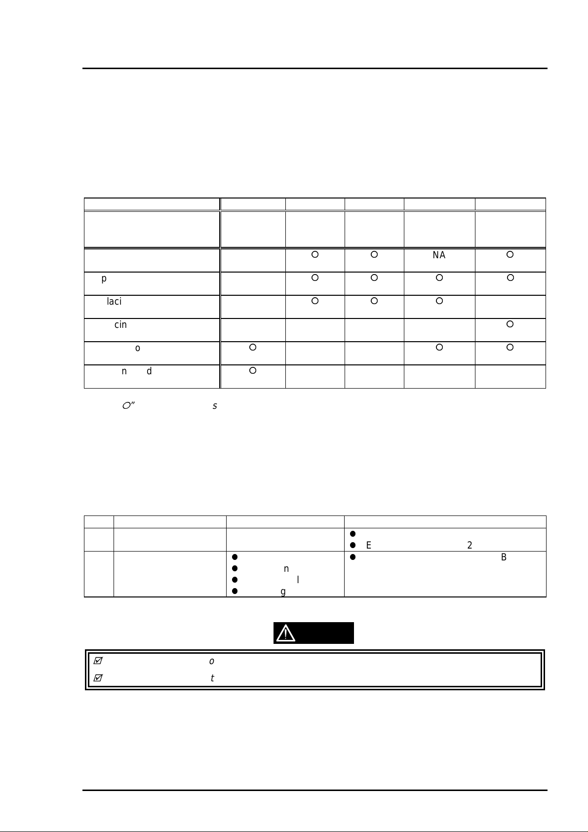
3. Move the carriage assembly to the middle, and put the thickness gauge at the position specified in the
figure.
4. Move the carriage assembly over the thickness gauge.
WORK POINT
The thickness gauge must be placed on a flat surface of the ribs of “PAPER GUIDE, FRONT;B”.
During adjustment, always pull the timing belt to move the carriage assembly.
5. Shift the position of “BUSH, PARALLEL ADJUST, RIGHT” to backward (Gap: Narrower) until when the
thickness gauge starts sliding together with the carriage assembly when you move it to right and left for
about 20mm.
6. At the point of above step, shift the position of “BUSH, PARALLEL ADJUST, RIGHT” for one notch to
forward (Gap: Wider).
7. Then, confirm that the thickness gauge do not slide when you move the carriage assembly, with either
“LEVER, PG” is at position “0” or “+”.
[Paper gap - Left-hand side Adjustment]
8. Repeat the above step 2 to 7 with “BUSH, PARALLEL ADJUST, LEFT”.
[Gap Confirmation]
9. Repeat the step 3 to 4 again.
10. Confirm that the thickness gauge do not slide when you move the carriage assembly to right and left
for above 20mm.
11. Shift the position of “BUSH, PARALLEL ADJUST, RIGHT” for one notch to backward (Gap: Narrower)
and confirm that the thickness gauge is sliding by moving the carriage assembly. If not, return to step 1
and repeat adjustment again.
12. If the gap is correct, shift “BUSH, PARALLEL ADJUST, RIGHT” for one notch to forward (Gap: Wider).
[Fixing “BUSH, PARALLEL ADJUST”]
13. Fix both bushes with 2 screws (1 each : No.1).
When the paper gap adj ustment complete, confirm that the overlap of printhead nose and “CLEANER,
HEAD”.
1. Move the carriage assembly next to “CLEANER, HEAD”.
2. Confirm that the overlap of printhead nose and top edge of “CLEANER, HEAD” is more than 0.5mm.
4-
Rev. A
Page 4
Chapter 4 Adjustment
3
Left
Rib: Avoid 2ribs from left
"ROLLER, ASSEMBLY, PF"
Figure 4-1. Paper Gap Adjustment - Thickness Gauge Setting
"PAPER GUIDE, FRONT;B"
Carriage
Assembly
"PAPER GUIDE, FRONT;B"
Right
(HP side)
[Thickness Gauge] Rib: Avoid 1 rib at right end
*Put the gauge on a flat face
*Align the center of gauge and
the ribs
"LEVER, PG"
Figure 4-2. Paper Gap Adjustment - Adjustment Procedure
Forward
(Gap: Wider)
Position Mark
Backward
(Gap: Narrower)
Side Frame
"BUSH, PARALLEL ADJUST, RIGHT"
Overlap = 0.5mm or more
Printhead
(Nose face)
"CLEANER, HEAD"
Figure 4-3. “CLEANER, HEAD” Overlap
Rev. A
4-
Page 5

EPSON Stylus Photo
4
4.2.2 Adjustment using Adjustment Program
Since the characteristic of printer mechanism and its components are varying, every printer mechanism
are checked and it’s own characteristic information is stored in EEPROM of the main control board as a
compensation parameter for the mechanism control. Therefore, if the combination of printer mechanism
and the main control board is changed, the printer should be adjusted using the adjustment program in
order to maintain optimum performance of the printer.
4.2.2.1 Overview of Adjustment Program
This adjustment program(K00A10VE.BAS) is developed specifically for this printer and the basic operation
with this adjustment program is illustrated in figure below.
Main Menu
(Item Selection)
Initial Ink Charge
Performance of Initial
ink charge process
Head VH voltage
ID writing.
Input of appointed
VH voltge ID
Head Angle
Adjustment
*Pattern printing
*Confirmation/
Mechanism
Adjustment
Figure 4-4. Adjustment Program Flow
Bi-D Adjustment
*Pattern printing
*Confirmation/
Input of correct
values
4-
Rev. A
Page 6

Chapter 4 Adjustment
5
4.2.2.2 Preparation for Adjustment
Before you start adjustment, have the following items ready for adjustment.
PC (MS-DOS Machine)
I/F cable (Parallel)
Brand new ink cartridges (Black and Color)
Photo quality ink jet paper (#S041061/2)
Printer that is necessary to adjust (At least, the printer mechanism, electrical
circuits, boards and panel should be connected.)
CAUTION
Make sure to use the new ink cartridge, which is not used and also not opened before.
Use the special ink-jet paper in order to check the adjustment result accurately.
1. Connect the PC to the printer and turn the PC and the printer on. Then, unpack a brand-new ink
cartridges and install them on to the printer.
2. Load “GWBASIC.EXE” and execute the adjustment program “K00A10VE”.
3. At the menu [SCREEN-1], input “2” to select “Cartridge” and press ENTER key.
4. Then, at the menu [SCREEN-2], input the number corresponding to your market and press ENTER
key.
[SCREEN-1] ***** TOOL ***** PM-700C/STYLUS COLOR PHOTO K00A10V e
1. Jig
2. Cartridge
Input ITEM No. : ?_
[SCREEN-2] ***** CUSTOMER ***** PM-700C/ STYLUS COLOR PHOTO K00A10Ve
1. 000: (WORLD)
2. 100: (JAPAN)
3. 000: (KOREA)
4. 000: (RUSSIA)
Input ITEM No. :?__
[SCREEN-3] <MAIN MENU for Production> STYLUS COLOR PHOTO K00A10Ve
1: VH Setting
2: Ink Charge
3: Angular Adjust Printing XX-XX-XXXX XX:XX:XX
K: Angular Adjust Setting
4: Bi-d Adjust CUSTOMER:WORLD
P: Print Inspection (GOS) Jig No. :CT
L: Print Inspection (S/F) M/C No. :
M: Print Inspection (Post-card)
HEAD VH :
CL. Cleaning:
9. INK Discharge
E. END / Go to SETTING MENU
Input ITEM No. :?_
Rev. A
4-
Page 7

EPSON Stylus Photo
6
4.2.2.3 Ink Charge Operation
If either of the following service is made, internal ink paths of the printhead unit is completely empty.
Therefore, a brand-new ink cartridge must be installed and all ink paths must be charged with fresh ink by
performing the following operation to ensure proper printing operation.
Replacing the printer mechanism
Replacing the printhead unit
CAUTION
Since this operation consumes large amount of ink, do not perform it unnecessarily:
*Black: Approx. 8.8% of the ink charged in the cartridge
*Color: Approx. 16.2% of the ink charged in the cartridge (CMYcm total)
The ink charge operation takes long time to complete. Do not turn off the printer until it stops
completely.(The POWER indicator blinks during the operation.)
1. Start “Preparation for Adjustment” and complete 1 to 4 procedures. (Refer to section 4.2.2.2)
2. At the main menu [SCREEN-3], input “2” to select “Ink Charge” and press ENTER key. Then, the
printer starts the ink charge operation.
4.2.2.4 VH Setting
The piezo-electric element used in each printhead unit has unique electrical characteristic and the
electrical characteristic of each printhead is measured at the production and each printhead unit is given
with the ID code. Therefore, this ID code is need to be stored in EEPROM on the main board when the
following service is made and the printer read this information to compensate the difference of
characteristic for printing control and an amount of injected ink is maintained at the specified level.
Replacing the printhead unit
Replacing the printer mechanism (the after-service unit comes with the printhead unit installed)
*Refer to the next page for [SCREEN -1] to [SCREEN-3].
1. When replacing the part mentioned above, take a note of the ID code indicated on the unit as below.
Printhead Unit: Stamped at the side of the unit
Printer mechanism: Indicated on a label attached to the packing box for the after-service unit.
2. Re-assemble the printer.
3. Start “Preparation for Adjustment” and complete 1 to 4 procedures.(Refer to section 4.2.2.2)
4. At the main menu [SCREEN-1], Input “1” to select “VH Setting” and press ENTER key.
5. At the next menu screen[SCREEN-2], input “0” as “M/C No.” and press ENTER key.
6. Then next menu [SCREEN-3] appears on the screen, and input the ID code which you noted at the
beginning of this procedure.
VH ID Code format: *1
*3
7. After inputting the ID code, the program returns to the m ain menu and you can continue to another
adjustments.
st/2nd
digits (from left) =Normal dot VH ID
rd
digit =Drive frequency ID
th/5th
digits =Micro dot VH ID
*4
WORK POINT
Timing to write the specified value to EEPROM: Upon pressing ENTER key after ID code input.
4-
Rev. A
Page 8

7
*[SCREEN-1] to [SCREEN-3] for VH Setting.
Chapter 4 Adjustment
[SCREEN-1]
[SCREEN-2]
[SCREEN-3]
MAIN MENU for Production >STYLUS COLOR PHOTO K00A10Ve
<
1. VH Setting
2. Ink Charge
3. Angular Adjust-Printing XX-XX-XXXX XX:XX:XX
K. Angular Adjust-Setting
4. Bi-d Adjust CUSTOMER:WORLD
P. Printing Inspection (GOS) JIG No. :CT
L. Printing Inspection (S/F) M/C No. :
M. Printing Inspection (Post-card)
HEAD VH :
CL. Cleaning
9. INK Discharge
E. Go to SETTING MENU
Input ITEM No.: ?_
M/C No. ?_
<<<< HEAD VH WRITE >>>>
Head VH ( 5 digit ID (ex.18109 or 18A0 ):
-------------------
M/C No. :0
HEAD VH :
M/C No. ? 0
VD VALUE
-------------------
Head VH ID
Viewed from front
Figure 4-5.Head VH ID Indication
Rev. A
4-
Page 9

EPSON Stylus Photo
8
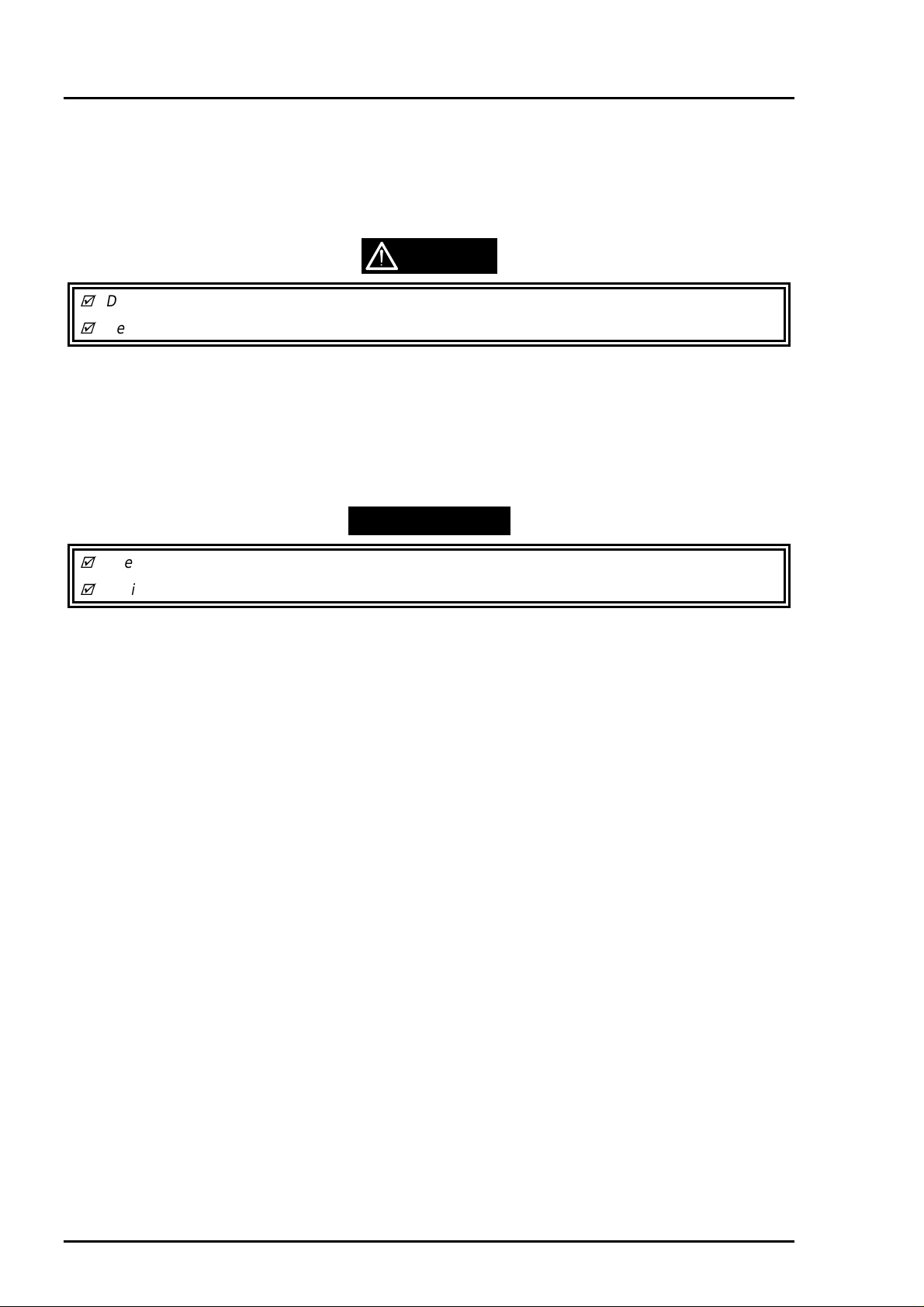
4.2.2.5 Head Angular Adjustment
The head angular means the angle at which the printhead unit installed on the carriage assembly against
the carriage movement direction and the printhead must be parallel with the carriage movement direction
so that the lines printed with each nozzle are evenly positioned. Therefore, this adjustment should be
made when the following service is made:
Replacing or removing the printhead unit
The head angular actually set by the adjust lever installed on the carriage assembly and the program print
the check pattern to see the level of head angular.
*Refer to next page for [SCREEN-1] to [SCREEN-2].
1. Before performing this adjustment, be sure to perform “VH Setting” (Refer to section 4.2.2.4)
2. At the main menu [SCREEN-1], input “3” to select “Angular Adjust Printing” and press ENTER key.
3. Check to see if the lines printed in MAGENTA color is positioned in the middle of two BLACK lines with
the check pattern printed by the program. If the position of MAGENTA lines are incorrect, input “K” to
select “Angular Adjust Setting” at the main menu and the carriage assembly moves to the middle of the
printer. Then, loosen a screw (No.3) fixing “FASTNER, HEAD” a little bit and shift the position of
angular adjust level located at the right bottom of the carriage assembly to either forward (move
MAGENTA line to down) or backward (move MAGENTA line to up).
4. After adjusting the position of angular adjust lever, input “Y” and press ENTER key and the carriage
assembly returns to the home position.
5. Input “3” to print the check pattern again. If the level is still not correct, repeat the step 3 and 4.
6. If the level is correct, input “K” again and tighten a screw to fix “FASTNER, HEAD”. Then, at the menu
[SCREEN-2], input “Y” and press ENTER key to complete the adjustment.
BLACK line
Printed pattern
Printed pattern
MAGENTA line
Shift the lever to:
Backward
Shift the lever to:
Forward
Angular Adjust Lever
(Right bottom of the Carriage Assembly)
Figure 4-6. Head Angular Adjustment
4-
Rev. A
Page 10

9
[SCREEN-1] to [SCREEN-2] for Head Angular Adjustment.
*
Chapter 4 Adjustment
[SCREEN-1]
CL.Cleaning
Input ITEM No. : ?__
[SCREEN-2]
MAIN MENU for Production >STYLUS COLOR PHOTO K00A10Ve
<
1. VH Setting
2. Ink Charge
3. Angular Adjust Printing XX-XX-XXXX XX:XX:XX
K. Angular Adjust Setting
4. Bi-d Adjust CUSTOMER:WORLD
P. Printing Inspection (GOS) JIG No. :CT
L. Printing Inspection (S/F) M/C No. :
M. Printing Inspection (Post-card)
9. INK Discharge
E. Go to SETTING MENU
Input ITEM No.: ? k
Angular Adjustment Finish (Yes):?_
HEAD VH :
Rev. A
4-
Page 11

EPSON Stylus Photo
0
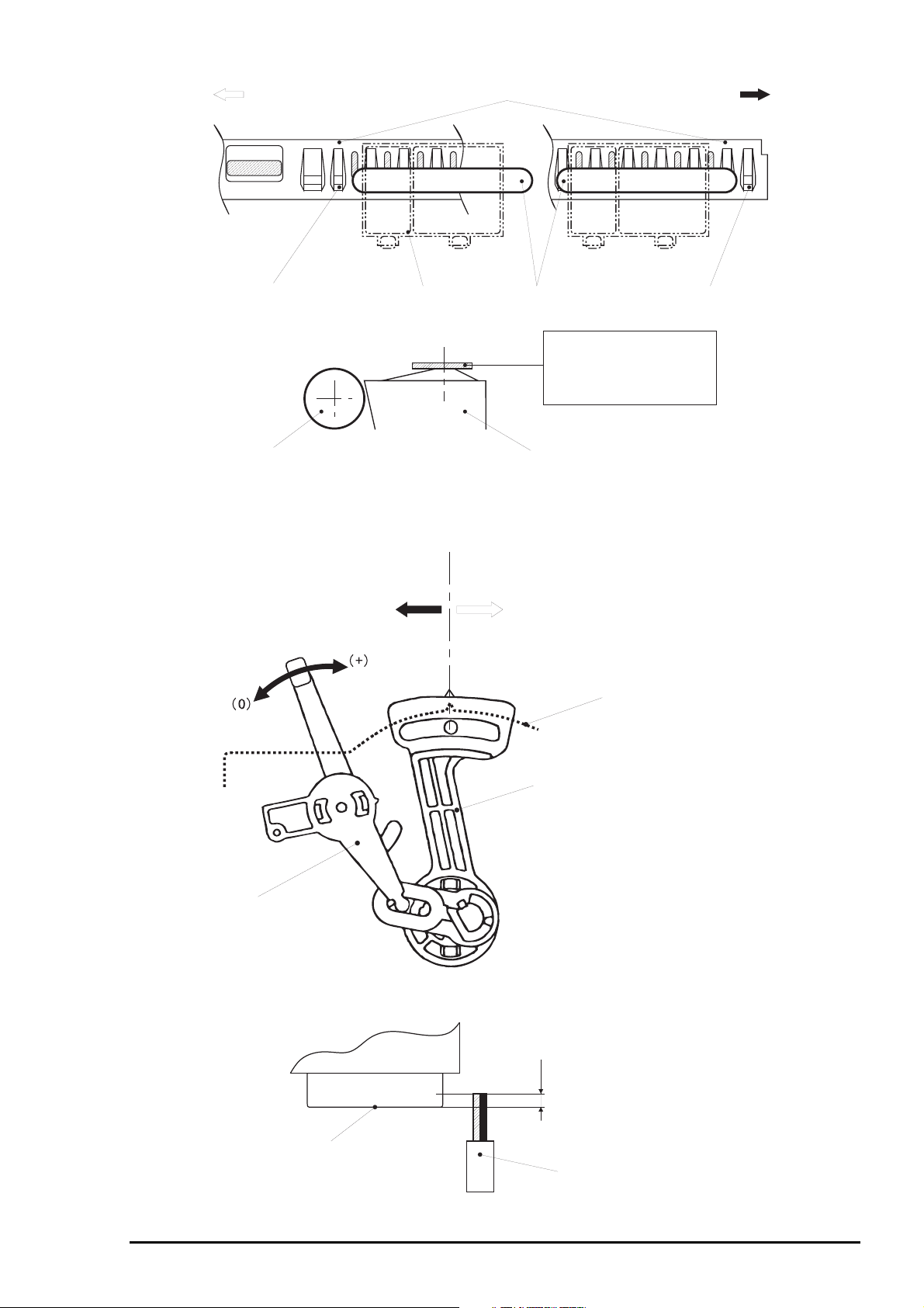
4.2.2.6 Bi-D Alignment Adjustment
This adjustment defines the carriage drive control parameters to compensate the variation in mechanism
components characteristic so that the print position become even in bi-directional printing. This
adjustment is required when one of the following service is made:
Replacing the printer mechanism
Replacing the main board (C209 MAIN)
Replacing the CR Motor assembly
Replacing the carriage assembly
The values defined with this adjustment are stored in EEPROM on the main board.
*Refer to next page for [SCREEN-1] to [SCREEN-3].
1. If the printer mechanism is replaced, the ink charge operation and the VH Setting operation should
be performed prior to this adjustment. (Refer to section 4.2.2.3 and 4.2.2.4)
2. Go to the main menu [SCREEN-1].
3. Input “4” to select “Bi-d Adjust” and press ENTER key.
4. The program prints the check pattern (one with the compensation value=“0” and another two patterns
each printed with the value “-2” and “+2”). Select the number of the pattern with which the printed lines
are most properly aligned, and input the number and press ENTER key at the menu [SCREEN-2].
Then, the program print the sample pattern with the compensation value you have selected.
5. If all patterns printed by the program are completely mis-aligned, confirm the inclination of
misalignment with the pattern printed with the value “0” by checking the relative position of the EVEN
line to the ODD line:
If EVEN line is shifted to RIGHT = Requires (−) value
If EVEN line is shifted to LEFT = Requires (+) value
Then, once input “Y” and press ENTER key to return to the main menu, and input “E” to select “Go to
SETTING MENU” and press ENTER key. At the setting menu screen [SCREEN-3], input “6” to select
“BI-D Center” and input the approximation number that corresponding to the inclination of
misalignment you have confirmed previously. After changing the reference value for the Bi-D alignment
check printing, input “1” to select “(Production)” and back to the main menu and continue for the Bi-D
alignment adjustment from step 4.
WORK POINT
Timing to write the specified value to EEPROM: Upon pressing ENTER key after input “Y”.
[Printed pattern]
Input (-) value
Input (+) value
Figure 4-7.Bi-D Alignment
4-1
Rev. A
Page 12

*[SCREEN-1] to [SCREEN-3] for Bi-D Alignment Adjustment.
Chapter 4 Adjustment
[SCREEN-1]
CL. Cleaning
[SCREEN-2]
MAIN MENU for Production >STYLUS COLOR PHOTO K00A10Ve
<
1. VH Setting
2. Ink Charge
3. Angular Adjust Printing XX-XX-XXXX XX:XX:XX
K. Angular Adjust Setting
4. Bi-d Adjust CUSTOMER:WORLD
P. Printing Inspection (GOS) JIG No. :CT
L. Printing Inspection (S/F) M/C No. :
M. Printing Inspection (Envelope)
9. INK Discharge
E. Go to SETTING MENU
Input ITEM No. : ?_
<< Definable Range (-30=< x <=30). >>
HEAD VH :
Input Adjust Value (If OK, input Y) :? _
[SCREEN-3] ***** SETTING MENU ***** K00A10Ve
1: (Production)/Adjustment
2:
3: DATE/TIME [XX-XX-XXXX] [XX:XX:XX]
4: TOOL [CT] JI=JIG CT=Cartridge WAIT=80s
5: CUSTOMER [WORLD]
6: BI-D Center [ 0 ]
7: Print Position [60]
Q: QUIT
Input ITEM No.: ?
Rev. A
4-1 1
 Loading...