

Page 1

Chapter 2
Operating Principles
2.1 OVERVIEW............................................................................................................2-1
2.1.1 Printer Mechanism ................................................................................................................. 2-1
2.1.1.1 Printing Mechanism................................................................................................... 2-2
2.1.1.2 Carriage Mechanism ................................................................................................. 2-7
2.1.1.3 Paper Feed Mechanism and Pump Mechanism......................................................2-11
2.1.1.4 Ink System............................................................................................................... 2-14
2.2 Electrical Circuit Operating Principles.............................................................2-18
2.2.1 C206 PSB/PSE Power Board ............................................................................................... 2-18
2.2.2 C209 Main Board .................................................................................................................. 2-20
2.2.2.1 Reset Circuits..........................................................................................................2-21
2.2.2.2 Sensor Circuits........................................................................................................2-22
2.2.2.3 EEPROM Control Circuits ....................................................................................... 2-23
2.2.2.4 Timer Circuit............................................................................................................2-24
2.2.2.5 Print Head Drive Circuit........................................................................................... 2-25
2.2.2.6 Motor Drive Circuits................................................................................................. 2-27
2.1.1.1.1 Printing Process.............................................................................................2-3
2.1.1.1.2 Printing Method..............................................................................................2-4
2.1.1.2.1 Paper Gap Adjust Mechanism ..................................................................... 2-10
2.1.1.4.1 Pump, Carriage Lock, Head Cleaner Mechanism........................................ 2-15
2.1.1.4.2 Cap Mechanism...........................................................................................2-17
2.3 Ink System Control.............................................................................................2-28
2.3.1 Ink System Basic Functions................................................................................................2-28
2.3.2 Timers and Counters............................................................................................................ 2-29
2.3.3 Ink System Sequence...........................................................................................................2-30
Page 2
Chapter2 Operating Principles
2.1 OVERVIEW
This section describes Printer Mechanism, electric circuit board (C206 PSB/PSE, C209 Main, C209PNL
board) of EPSON Stylus Photo.
2.1.1 Printer Mechanism
Unlike the previous EPSON Ink Jet printers, printer mechanism of EPSON Stylus Photo does not have
exclusive mechanism to change over paper feeding and pumping operation. In stead, this control is done
by the turning direction of paper feed/pump motor and changing the position of carriage at that time.
Also, unlike previous print heads, the print head of this printer became one unit combined with black,
CMY(Cyan, Magenta, Yellow), LM(Light Magenta) and LC(Light Cyan) head. Black head has 32 nozzles,
90 dpi(vertical direction) and CMY, LC, LM head has 32 nozzles for each color, 90 dpi (vertical direction).
Also, since these print head is driven by frequency 14.4KHz, this printer can print twice faster (200-dpi)
than Stylus Color even at 720-dpi high resolution printing. Since the head drive frequency of Stylus Color
was 7.2KHz, it was driven by 100-cps printing speed in order to perform 720-dpi printing.
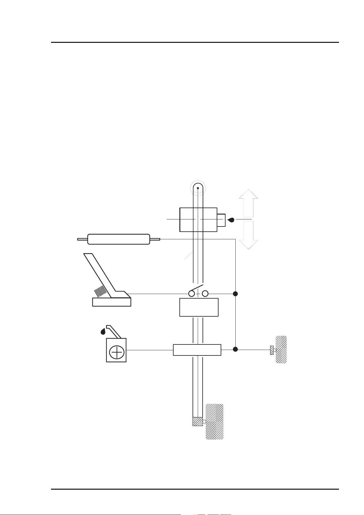
Following figure2-1 shows outline of the printer mechanism
Carriage Unit
(Prinr Head Unit)
.
Platen Drive Mechanism
Paper Pickup Mechanism
Pump Drive Mechanism
Timing Belt
Paper Pick Up
Trigger Lever
Pumping Position
Paper Feed Motor
Rev. A
Carriage Motor
Figure 2-1. EPSON Stylus Photo Printer Mechanism Block Diagram
2-1
Page 3
EPSON Stylus Photo
2
As you can see major printer mechanisms in the figure 2- 1, there are four m ajor mechanis ms as they are
listed below.
1) Printing mechanism 2) Carriage drive unit 3) Paper pick up mechanism 4) Pump drive mechanism
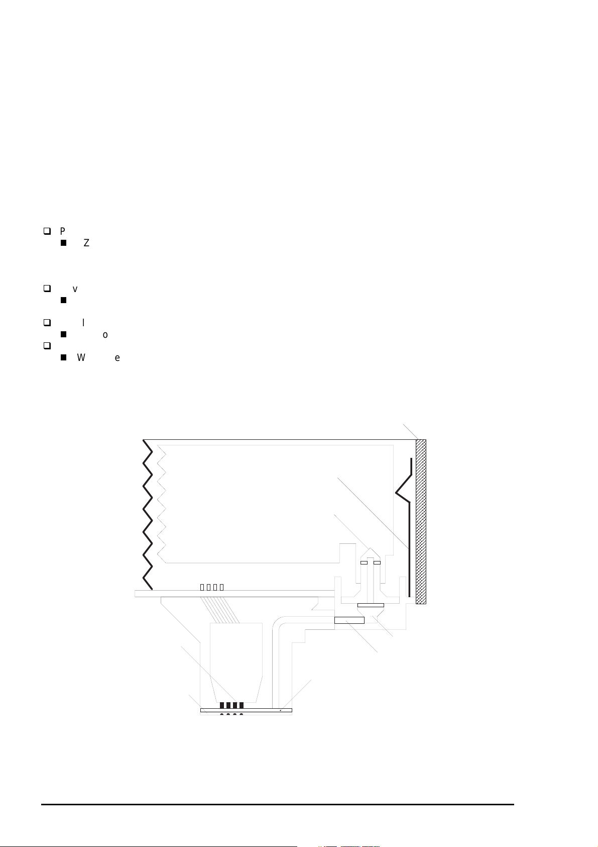
2.1.1.1 Printing Mechanism
Basic operating principles of the print head which plays major role of printing mechanism is the same as
previous models; on demand type MACH head method, but there is some differences in the resolution.
(Refer to figure1-1) Also, unlike Stylus Color II, Stylus 820 and Stylus Color 200 automatic correction type,
in order to fix the dispersion of mufti layer piezo electric element which is used for driving each nozzles, it
is necessary to input the VH value written on the side of print head by using exclusive program when you
replace the print head, control board, or the printer mechanism.(However, there are no resistor array to
decide the VH voltage on the main control board.) Following explains the print heads.
PZT
PZT is an abbreviation of Piezo Electric Element. Print signal from C209 board is sent through the
driver board on the print head unit and to the PZT . Then, the PZT pushes the top cavity which has
ink stored, and make the ink discharge from each nozzle located on the nozzle
plate.
Cavity Set
Ink which is absorbed from ink cartridge go through the filter and will be stored temporarily in this
tank, which is called “cavity”, until PZT is driven.
Nozzle Plate
The board with nozzle holes on the printer head surface is called Nozzle Plate.
Filter
When the ink cartridge is installed, if any dirt or dust around the cartridge needles are
absorbed into the head inside, there is a great possibility of causing nozzle clog and
disturbance of ink flow and finally causing alignment failure and dot-missing. In order to
prevent this, filter is set at cartridge needle below and ink is once filtered here.
PZT
Nozzle Plate
Printhead driver board
Ink Cartridge Sensor
Actuator
Cartridge needle
(Ink Cartridge)
Filter
Ink Supply Tube
Cavity set
Figure 2-2. Print Head Sectional Drawing
2-
Rev. A
Page 4
Chapter2 Operating Principles
3
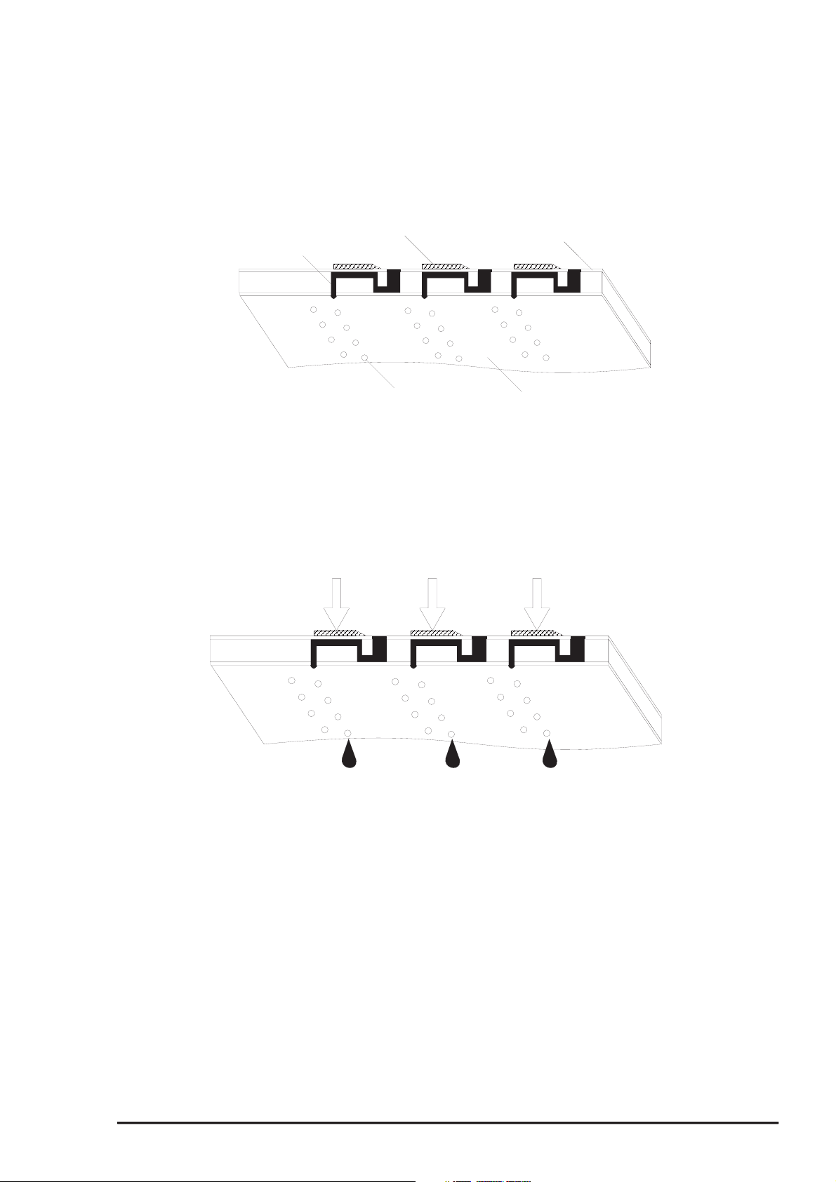
2.1.1.1.1 Printing Process
Following figures indicate the sectional drawing of normal state and ejecting state of print head.
(1) Normal State:
When the printing order is not output, PTZ also does not move and stays in the waiting mode
(normal state).
PZT
Cavity
Ink Course
Nozzle
Figure 2-3. Print Head Normal State
(2) Ejecting State:
When the print signal is output from the C209 main board, IC(IR2C72C and IR2C73C:Nozzle
Selector) located on the print head unit latches the data once by 1-byte unit. Appropriate PZT latched
by nozzle selector is pushed in to the cavity by applying common voltage from the C209 main
board. By this operation, ink that is stored in the cavity pops out from nozzles.
Nozzle Plate
Figure 2-4. Print Head Ejecting State
Rev. A
2-
Page 5
EPSON Stylus Photo
4
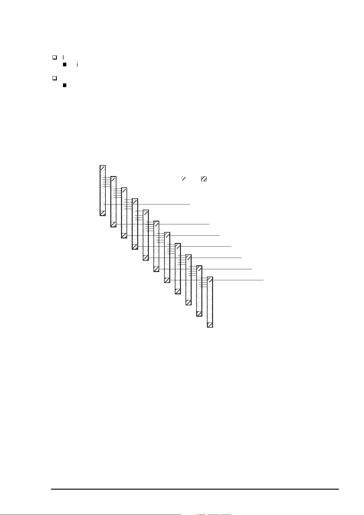
2.1.1.1.2 Printing Method
This section explains printing method of actual printing such as printing text at various resolution
select/printing mode and graphics printing. In order to prevent white or color banding which are peculiar
problem of ink-jet, new Micro-Weave functions are added to the previous Micro-Weave function. The
number of nozzles and printing mode according to the selected resolution are used separately by a user.
The table below shows relation between selected resolution and printing mode.
1) Full Overlap Micro-Weave
2) Part Line Overlap Micro-Weave
3) Micro-Weave: (same as previous control)
Table 2-1. Resolution and Printing Mode
Vertical
direction
[dpi]
360 FOL M/W 15/360 #16•`#30 --- #1•`#15 #31, #32
720 FOL M/W 15/720 #16•`#30 --- #1•`#15 #31, #32
Note1:
M/W means Micro-Weave.
Note2:
Note3:
Note4:
Following explains operation outlines of new Micro-Weave functions listed above.
[1. Full Overlap Micro-Weave]
In order to print one line at horizontal direction, this printing method is designed to complete a printing
pattern by two-pass carriage operation with two different types of dot. When these two different types of
dot pass one same line twice, it does not print the same dot twice. Following explains the outline of this
movement.
FOL means Full Overlap Micro-Weave.
POL means Part line Overlap Micro- Weave
Forward Overlap-Nozzle and backward Overlap -Nozzle are described in the [1.Full Overlap
Mirco-Weave] and [2.Part line Overlap Micro-Weave] below.
The number of all nozzles which are going to be used are divided equally into 2 groups.
Paper feeding will be done as many as each number of nozzles which are divided into two groups
and the same number of dots.(for example, if there are two 10-nozzle groups during 360-dpi
printing at longitudinal direction, paper feeding of 10/360-inch becomes available.)
At this time, two groups perform Micro-Weave individually and particular lines are passed by
two different nozzles.
Printing
mode
M/W 31/360 --- #1•`#31 --- #32
POL M/W 29/720 #30•`#32 #4•`#29 #1•`#3 ---
Paper feed
pitch
[inch]
Forward
Overlap-
Nozzle
Non
Overlap-
Nozzle
Backward
Overlap-
Nozzle
Not used
Nozzle
.
Note1)
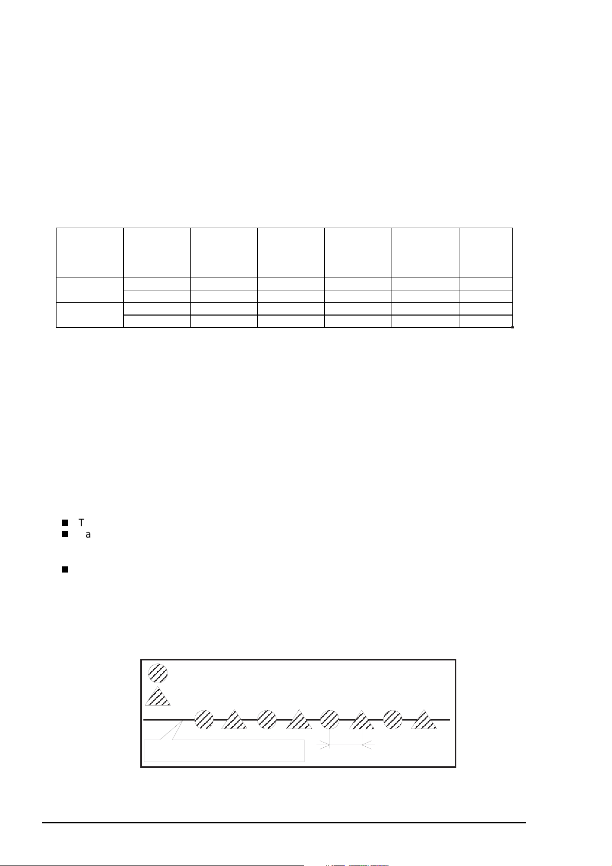
Two groups which are divided according to each elements will be divided either even dot or
odd dot when particular lines(level direction line) are formed and eventually, these lines will be
completed at selected resolution. Following is a conceptual figure when full overlap microweave forms a particular line.
Nozzle No.#9
Condition: 360-dpi printing
Nozzle: Total 10 nozzle/each color
Nozzle No.#4
Particular line(Completed line)
Figure 2-5. Full Overlap Micro-Weave
2-
360-dpi
Rev. A
Page 6
Chapter2 Operating Principles
5
Note 2)
If the line which is about to be printed is even line:
If the line which is about to be printed is odd line:
[2.Part Line Overlap Micro-Weave]
This printing method is to perform Micro-Weave printing, overlapping part of nozzles which are
used for printing. As a result, a part of line which is overlapped consists of different browse with
different nozzles. The figure below shows 1-line overlap at 5-dot sending as an example with
explanation on the next page.
The way firmware decides which nozzle becomes even dot or odd dot is determined
as it is described below.
First dot prints odd dot lines and 2nd dot prints even dot lines.
1st dot prints even dot lines and 2nd dot prints odd dot lines. Eventually, horizontal resolution
will be the same resolution as selected one.
Pass1
#1
#2
#3
#4
#5
2
3
Note1: The paper feed pitch is 5/360-dpi in this figure.
Note2: Mark of and mean overlap nozzle.
4
5
Raster 1
#6
6
7
Raster 10
8
9
10
11
Figure 2-6. Part line Overlap Micro-Weave
Rev. A
2-
Page 7

EPSON Stylus Photo
6
The difference between Full-Overlap Micro-Weave and Part line Overlap Micro-Weave are
following;
Full-Overlap Micro-Weave:
Printing is performed, judging if nozzles are even or odd dot by 2 different dots in all
different lines.
Part line Overlap Micro-Weave:
After particular nozzles(only#1, and #6 in the figure2-6) are determined as overlap nozzles,
even or odd dot will be determined like Full-overlap Micro-Weave does.
(Forward Overlap Nozzle is determined as even and backward nozzle is odd.)
Also, nozzles other than particular nozzles can print at even and odd dot just by one
nozzle.
1) Overlap Nozzle : Head drive frequency is driven half of the ordinal one like 2)
below.
2) Nozzle other than Overlap nozzle : Head drive frequency is twice as much as overlap nozzle.
Usually, the firmware changes over automatically these full overlap Micro-Weave, Part line Overlap
Micro-Weave, and ordinal Micro-weave according to the selection of resolution. Also, when these three
printing modes are performed by the EPSON Stylus Photo, the printer performs top and bottom margin
process in order to control the overprinting volume as little as possible.
2-
Rev. A
Page 8
Chapter2 Operating Principles
7
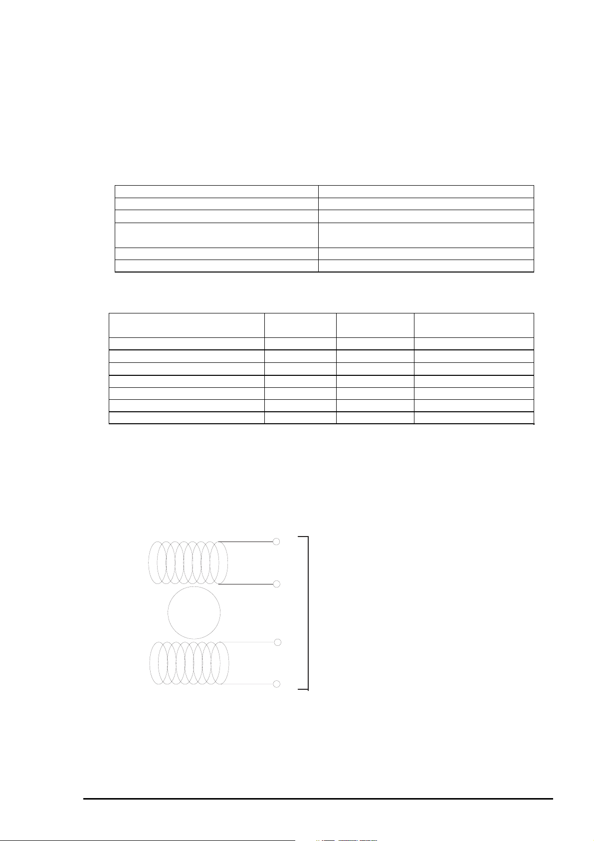
2.1.1.2 Carriage Mechanism
Carriage mechanism is to drive the carriage with print head from left to right or vice versa.
The carriage drive motor in this printer is a 4-phase, 200-pole stepping motor and is driven by
1-2phase, 2-2phase and W1-2phase drive method. This stepping motor allows the carriage to
move freely to the particular positions which is necessary for various operation, such as paper feeding,
ink absorbing, flashing, ink exchange and cleaning operations. The tables below show carriage motor
specifications and motor controls at each mode.
Table2-2. Carriage Motor Specification
Item Description
Motor type 4-phase/200-pole Stepping motor
Drive voltage Range
Internal coi l resistance
Driving speed(frequency) range[cps (pps)] 5(60) - 340(4080)
Control method Bi-Pola Drive
Table 2-3. Motor Control at each mode
42VDC ±5%
7.8 Ohms ±10%
(per phase under 25°C environment)
Mode Driving speed
[CPS]
High speed skip 340 4080 W1-2, 2-2,1-2phase drive*
Printing(1→ 80 column direction)
Printing(80→ 1 column direction)
Capping 80 960 W1-2phase drive
Wiping 40 480 W1-2phase drive
Cap(valve released) 20 240 W1-2phase drive
Cap (Release) 5 60 W1-2phase drive
*Note 1):
Acceleration 1 mode → Acceleration 2 mode → Deceleration 1 mode → Deceleration 2 mode
The reason why plural drive methods exist is that following some sequences described below
exist in the each mode and, more stable carriage operation and printing are performed
individually by different drive methods. This drive method is necessary especially for high
speed skip.
200 2400 W1-2phase drive
200 2400 W1-2phase drive
Drive frequency
[PPS]
Drive method
1
A
3
/A
C209 MAIN Board
Rotor
2
CN6(CN7)
B
4
/B
Figure 2-7.CR(PF/Pump) Motor Internal Block Diagram
Rev. A
2-
Page 9
EPSON Stylus Photo
8
The table below shows W1-2 phase drive sequence at each steps when the rotor of carriage motor
makes one rotation. In the EPSON Stylus Photo, in addition to a function that printing is performed with
W1-2 drive phase, high s peed skip mode which is a function to s kip over the blank from the end of the
printing data to the next data starting point in high speed, can be also performed by 2-2 and 1- 2 phase
drive. W1-2 phase requires 4 times as much steps as 2-2 phase drive, calculating 2-2 phase as standard.
By using this method, it becomes possible to supply constant and stable torque to the motor. As a result, it
also becomes difficult to be influenced by vibration from the printer mechanism during printing.
Table 2-4.Motor Drive Sequence(W1-2.phase drive)
Sequence
Number
Phase a 10a l1a Current
0010+2/3010+2/3
1001+1/3000+1
2X110000+1
3101-1/3000+1
4110-2/3010+2/3
5100-1X01+1/3
6100-11110
7100-1101-1/3
8110-2/3110-2/3
9101-1/3100-1
10X110100-1
11001+1/3100-1
12010+2/3110-2/3
13000+1101-1/3
14000+1X110
15000+1001+2/3
This W1-2 phase drive (or 2W1-2 phase drive) is called Micro-step and is attached with so called
2/3•EVref or 1/3•EVref factor, compared with drive current value (Vref100%) which is supplied at 22phase drive. This Micro-Step allows the rotor to have delicate rotation. In the 2-2 phase drive method, it
is usually
required to take 4-step sequence in order to rotate the rotor once. However, in case of W1-2 phase,
it is required to take 16-step sequence(in the table 2-4, sequence 0•`15) which is 4 times more than
2-2 phase method to do that. Also, in case of 2W1-2 phase drive which can be seen in the Stylus Color
etc., it takes 2-step to rotate the rotor once. The table below shows relation of rotation direction of the rotor
and carriage proceeding direction.
Phase A Phase B
Phase b 10b l1b Current
Duty
Duty
Table 2-5. Relationship Between Rotation Direction and Carriage Operation
Carriage proceeding
direction
HP→80 column direction
80 column→HP direction
Note)
1* Looking from rotor shaft side.
2-
Rotation direction of
Rotor 1*
Clockwise direction 2-2, 1-2, W1-2 phase
Counterclockwise
direction
Drive method Proceeding order of
2-2, 1-2, W1-2 phase
sequence
Sequence No.0→15
Sequence No.15→0
Rev. A
Page 10
Chapter2 Operating Principles
9
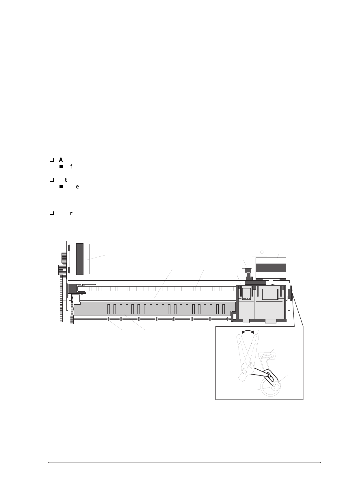
The figure below shows carriage mechanism. The print head as a core of the printing mechanism is
installed in the carriage unit. This print head keeps the angle of print head in flexible and adjustable
structure by moving the adjustment lever up and down with the Angular adjustment mechanism.
(Refer to chapter 4 for more details) Also, parallelism adjustment lever is mounted on right side of the
carriage guide shaft and it adjusts parallelism between paper and shaft when this shaft is installed to the
printer mechanism.
After this adjustment is completed, operating the PG adjustment lever makes possible to change the
space between the surface of paper and print head surface into 2 phases; either 1.04mm to 1.94mm. It is
possible to vary the space between the surface of paper feed assembly and the print head by rotating the
axis of carriage guide shaft which itself is decentralized, with the operation of PG lever. This is the
mechanism that user can adjust the appropriate PG value by himself according to the paper thickness or
any other environmental conditions such as paper curl.
Carriage lock mechanism is to prevent the carriage from being left uncapped for a long time because of
vibration during the printer transport or mishandling by the users. If the carriage is left uncapped for a long
time, an ink on the print head surface gradually becomes viscosity. As a result, the nozzle will be unable to
discharge ink. To make matters worse, the nozzle may be completely clogged by the viscosity ink and it
may not be able to return to the normal condition just by the normal cleaning operation. In order to prevent
this, printer goes to carriage lock state at the following conditions.
After Power OFF operation:
If the power is turned off during the printing or any other performance, carriage lock will be
performed in the end after completing initialize operation.
After power ON operation:
After power is turned on and automatic P-On Cleaning(power on cleaning) is performed, then
carriage lock will be performed. The timer IC always counts printer’s power OFF time by using
the power of lithium battery mounted on the C209 main board. P-on cleaning function
automatically selects the cleaning level according to the time which the printer is not in used.
After Eject the paper:
After Load/Eject button is pressed and the paper is ejected, if the data is not input, the printer
performs carriage lock and goes to standby state. However, if the paper is loaded to the printer
inside by Load/Eject button, the printer does not perform the carriage lock operation.
Paper Feed Motor
Eject Roller
Paper guide(Front)
Carriage home position Sensor
PF Roller
Timing Belt
Carriage Unit
Figure 2-8. Carriage Mechanism(Top Viewing)
Front Side
Carriage
Guide Shaft
Carriage Motor
Rear Side
Parallelism
Adjust Lever
Fixing Bush
Rev. A
2-
Page 11

EPSON Stylus Photo
0
2.1.1.2.1 Paper Gap Adjust Mechanism
This mechanism can be set by the users and can prevent various problems related to low image density
or print with any dirt by changing the positions of PG lever according to the paper types.
Table 2-6. PG Lever Setting
Paper Lever Position PG Value
Normal paper,
Coated paper
Envelopes Rear 0.9mm
It is a major premise that parallelism adjustment is done correctly for the space between head and paper
(PG value above) which can be changed by adjusting the paper gap.
Parallelism adjustment should be done when the serviceman mounts the carriage guide shaft on the
printer mechanism during repair service. In the adjustment, the space should be adjusted to 1.04 mm,
using a thickness gauge.
Front 0 mm
(1.04mm between head and paper feed
assembly)
(1.94mm between head and paper feed
assembly)
2-1
Rev. A
Page 12

Chapter2 Operating Principles
2.1.1.3 Paper Feed Mechanism and Pump Mechanism
Mechanisms that send the paper in the hopper to inside the printer and perform constant paper
feed in order to perform printing on the sent paper are called paper feed mechanism as generic name.
In the EPSON Stylus Photo, 4-phase, 200-pole hybrid type pulse motor is used in the PF motor as a
motive power for the paper mechanism and driving is done at 2-2 and 1-2 phase drive method.
This motor is not only used as a power source for paper feed mechanism but also used as power source
for pump mechanism which is necessary for the print head cleaning. By using this pulse motor, it becomes
possible to use high speed drive or intermittent drive for the various paper feeds and pump operations,
such as paper feed, slight paper feed, high and low speed absorption of pump operations. Following
tables(Table 2-7 and 2-8) show PF motor specifications and control method at each mode.
Table 2-7. PF Motor Specification
Item Description
Motor type 4-phase/200-pole Stepping motor
Drive voltage
Coil Resistance
Drive frequency 400-4320Hz
Control method Bi-Pola Drive
42VDC±5%
7.8 ohms±10%
(per 1 phase under 25°C environment)
Table 2-8. Motor Control Method at Each Mode
Mode Drive Method Drive Frequency
[Hz]
Paper feed A 2-2 phase 4320 231
Slight paper feed 1-2 phase 400 2500
Slight paper feed 1-2 phase 2400 417
High speed attraction of pump 2-2 phase 4100 243
Low speed attraction of pump 1-2 phase 1800 555
Low speed paper feed 1-2 phase 1200 833
Paper feed B 2-2 phase 3400 294
Paper feed C 1-2 phase 4000 250
Ordinal absorption of pump 1-2 phase 4100 243
Following tables show 1-2phase drive method at PF motor drive and each drive sequence at 2-2phase
drive method.
Table 2-9. 1-2 Phase Drive Method
Step No. Clockwise Counter clockwise
Phase A Phase B Phase A Phase B
1 +2/3 +2/3 +2/3 +2/3
0+1+10
2 -2/3 +2/3 +2/3 -2/3
-1 0 0 -1
3 -2/3 -2/3 -2/3 -2/3
0-1-10
4 +2/3 -2/3 -2/3 +2/3
+1 0 0 +1
Pulse Space
(ƒÊs)
Table 2-10. Drive Sequence at 2-2 Phase Drive
Step No. Clockwise(CW) Counter clockwise(CCW)
AB A B
1 +2/3 +2/3 +2/3 +2/3
2 -2/3 +2/3 +2/3 -2/3
3 -2/3 -2/3 -2/3 -2/3
4 +2/3 -2/3 -2/3 +2/3
Rev. A
2-1 1
Page 13

EPSON Stylus Photo
2
Papers on the ASF (auto-sheet-feeder) supplied by the user are carried to the printer inside by paper
pick up sequence. Unlike the previous models, ASF of EPSON Stylus Photo has multi feed prevention
mechanism. Following explains this function and figure below shows its mechanism.
[1. Multi feed prevention mechanism]
When the Load/Eject button is pressed, reversed rotation of PF motor is performed.
The return lever resets papers which are already in the out of stand by position and make it possible to
perform stable paper feeding by picking up the paper again.
Pintch Roller
D-Cut Roller
CAM
Hopper
Hopper spring
3)
1)
Pad spring
Return Lever
Pad
[Standby state]
Figure 2-9. Multi Paper Feed Prevention Mechanism
Following explains process of multi feed prevention step by step. Refer to the figure above and confirm
its operation.
2)
[Returning state]
[Step 1]
PF motor rotates counterclockwise and makes the CAM rotate towards direction of 1) in the
figure above.
[Step 2]
[Step 3]
[Step 4]
When the Load/Eject button is pressed or the signal of printing order is input from the PC,
When the CAM covers the notch by the return lever, that position is considered as home
position, being monitored by ASF sensor.
When the CAM rotates toward 1) in the figure above, the return lever is pushed by the notch
of CAM and falls towards 2). At this time, the return lever moves to direction 3) by this
motion, and push down the pad which is waiting in the below part. At this time, friction of
pinch roller and pad will be canceled.
The papers which are out of stand by position by the previous paper feed motion are
returned to the paper stand by position by flip over strength of return lever. After this,
PF motor rotates clockwise and the printer goes to pick up sequence.
2-1
Rev. A
Page 14

Chapter2 Operating Principles
3
In the paper pick up mechanism of EPSON Stylus Photo, same mechanism as Stylus Color IIs/820
are applied. This mechanism changes adjoined lines of gear by colliding trigger lever with carriage
unit, and convey the motive power on the paper feed assembly to the ASF side(paper roller). The figure
below shows mechanism with explanation.
[2. Paper pick up mechanism]
When the Load/Eject button is pressed or printing order is input, the carriage unit moves to
the left edge and collides with paper pick up trigger lever. When the carriage collides with this trigger
level, a planetary gear located on the same axis is also pushed at the same time and conveys
the motive power on the paper feed assembly to the adjoined gear line side for ASF drive.
Paper Pick Up
ASF Roller Drive Gear
Planetary Gear
Trigger Lever
Eject Roller Drive Gear
Eject Roller
Transmission Gear
PF Motor Pinion Gear
ASF Roller Transmission Gear
PF Roller Drive Gear
PF Roller Transmission Gear
Figure 2-10. Paper Pick Up Mechanism
[3. Paper feed mechanism]
After papers in the ASF receive controls from pick up and multi feed prevention mechanism, they are
sent to the printer inside. The papers picked up by paper roller in the ASF goes to between paper feed
assembly and roller support. Also, the eject roller pushes out the paper completely to the end and the
roller support drops the paper in the eject tray. The eject roller is driven with an eject paper notched roller
as pair where is located on the paper eject roller. Paper eject notched roller solves the deflection of paper
that is in between eject notched roller and paper eject roller and always keep a certain space between the
print head and paper surface. The figure below shows paper feed mechanism.
Paper
Eject Notched Roller
Support Roller
PF Roller
Eject Roller
Figure 2-11. Paper Feed Mechanism
Rev. A
2-1
Page 15

EPSON Stylus Photo
4
2.1.1.4 Ink System
Ink system mechanism consists of 1)cap mechanism, 2)pump mechanism, 3)carriage lock mechanism,
4)waste ink absorber and 5)ink sequence. Out of these mechanism, from 1) to 4) are physical mechanism
and parts which are mounted on the printer mechanism, and 5) ink sequence is performed automatically
by the firmware. Also, unlike the previous models, since EPSON Stylus Photo has no engage/disengage
mechanism to change over pump mechanism and paper feed mechanism, it is one of the major
characteristics that pump and paper feed assembly are always at work whenever the PF motor is driven.
The figures below shows head positions when the ink system and various ink sequence are performed.
PF Roller Drive Gear
Eject Roller Drive Gear
Eject Roller
Trasmission Gear
Head Cleaner
Carriage Lock
PF(Pump) Motor Pinion
Pump Roller
Figure 2-12. Ink System Mechanism
Printable Area
2975 dot
A: Dummy pumping position
B: Home position
C: Flashing position(right side)
D: I/C replacing position
E: Wipping complete/Rubing start position
F: ASF Standby position
G: Flashing position
H: ASF pick up position
Cap Unit
CRHP
ABCDEFGH
Figure 2-13. Major Ink Sequence Position on the Carriage Mechanism
2-1
Rev. A
Page 16

Chapter2 Operating Principles
5
2.1.1.4.1 Pump, Carriage Lock, Head Cleaner Mechanism
In the EPSON Stylus Photo, there is no button or mechanism to change over the pump/paper feed
mechanism. Therefore, whenever the paper feed/pump motor rotate, the pump drive roller in the pump
unit inside rotates. However, ink absorbing/non ink absorbing are separated by the roller rotational
directions. Also, even if the pump drive roller(pump motor) rotates toward ink absorbing and the carriage
is in the false absorbing position, only driving in the pump mechanism is performed and actual ink
absorption is not done. The figure below shows process of conveying motive power to the pump drive
roller.
Gear A
Axis of Paper Eject Roller
Gear B
Gear C
Actually, these parts
are one unit.
Compression
Spring
Pump Drive Roller
Figure 2-14. Pump Mechanism Power Transmission Process
The process of conveying the motive power to the paper eject roller by rotating the pinion of PF motor
is shown in figure 2-12. This motive power is conveyed to the Gear C through Gear B.
In the figure above, although the lever in order to drive Gear C, carriage lock, head cleaner mechanism
is shown separately, it is constructed as one unit. Since the engagement of these two parts depends on
the tension of the compression spring, if the lever is burdened, only Gear C and pump roller rotate and no
more motive power is conveyed to the lever part.
Rev. A
2-1
Page 17

EPSON Stylus Photo
6
The table below shows PF/Pump motor rotational direction and pump system operation.
Table 2-11. Relationship Between Pump Motor Rotation and Pump Operation
PF/Pump motor rotational direction Pump unit operation
Clockwise(CW)
forward rotation
1)Released from the pressured pump
2)Head cleaner reset
3)Carriage lock reset
Counterclockwise(CCW)
backward rotation
1)Move to the state that pump is pressured
2)Head cleaner set
3)Carriage lock set
The figure below shows the pump operation at clockwise and counterclockwise rotations.
CCW Rotation
CW Rotation
Tube pressured
Tube released
Figure 2-15. Pump Roller Rotation and it’s Operation
In the ink absorptive operation such as cleaning, flushing initial ink charge except for printing operation,
ink in the ink cartridge drains to the waste ink absorber(pad) through the cap by the pump unit drive.
In case of printing and flushing, ink is popped out by the PZT in the print head, but in case of
absorptive operation such as cleaning and initial ink charge, ink absorption is performed
only by the pump drive without PZT drive after the head surface is adhered to the cap.
The next page explains cap mechanism and relation between printer operation and cap mechanism.
2-1
Rev. A
Page 18

Chapter2 Operating Principles
7
2.1.1.4.2 Cap Mechanism
In the cap mechanism, in order to prevent ink from being viscosity on the head surface, it is controlled
that the head surface stays adherent to the rubber frame of the cap surface when the power is off.
The absorber is spread in the cap and can hold a certain amount of ink which is absorbed from the
head without draining it to the waste ink pad. Also, in the bottom of absorber, there are two valves in
order to control adhesion of head and cap surface, and one exits to drain ink to the waste ink pad.
A
Flag for Carriage
Ink Eject Valve
Negative pressure
release valve
Valve
Close state
B
Release state
Flag for frame
Head surface and
cap are adhered
each other.
Actual and false
absorptions.
During cleaning, initial ink
charge, and right flushing.etc.
Ink absorption in
the cap.
During left flushing and paper
feeding,etc.
Figure 2-16. Cap Mechanism Operation Principle
If the carriage is out of HP(in this case, in the printable area or paper feed position), the valves on the
cap mechanism stays in the position A in the figure above and are always closed. In this condition,
the carriage collides with flag, actual ink absorption and slight ink absorption are performed.
Also, by moving the carriage to further right side and colliding the flag for opening the valves with
the frame, negative pressure is released in the state that head surface and cap are adhered. This
makes it possible for ink in the nozzle to be ready for being ejected from the cap in
the stable condition.
Rev. A
2-1
Page 19

EPSON Stylus Photo
8
2.2 Electrical Circuit Operating Principles
EPSON Stylus Photo contains the following four electric circuit boards.
C206 PSB/PSE board
C209 Main board
Head Driver board
C209 PNL board
C206 PSB/PSE, C209 main board are explained in this section. The head drive board is installed in the
head unit the carriage. The figure below shows electric circuit block diagram.
Printer Mechanism
CR Motor
C209 PNL Board
C206PSB Board
+42VDC
+5VDC
C209 Main Control Board
PF/Pump Motor
Head Drive Circuit
Various Sensors
Figure 2-17. Electric Circuit Block Diagram
2.2.1 C206 PSB/PSE Power Board
C206 PSB/PSE board is a power supply board with a RCC switching regulator, which generates +42VDC
for drive part and +5VDC for logic part to drive the printer. The table 2-12 below shows application of
voltages generated by C206 PSB/PSE board.
Table 2-12. Application of DC Voltage
Voltages Application
+42V
+5V
Motors(CR Motor, PF/Pump Motor)
Print Head Common Voltage
C209 Main control Board logic
C209PNL Panel Board
Sensors (HP sensor, ASF HP sensor, PE sensor)
The power switch of this printer is in the secondary circuit that allows the PSB/PSE board to continue to
supply voltage for both power and logic line for at least 30 seconds until the printhead returns to the
capping position even if the printer turned off during printing. This prevents ink leakage or dried print head
caused by the print head being left uncapped. The AC voltage from the AC inlet is first input to the filter
circuit for higher harmonics absorption and is then input to the rectification and smoothing circuit,
converting into DC voltage. This DC voltage is then input to the switching circuit. Along with this switching
operation by FET on the primary side, +42V voltage is generated and stabilized on the secondary side,
which is then converted into the stable +5V VDC by the chopping regulator IC.
Figure 2-18 shows the block diagram of the electrical circuit.
2-1
Rev. A
Page 20

9
Primary Side
Chapter2 Operating Principles
Secondary Side
Full Wave
Rectifier Circuit
Filter Circuit
AC Input
Smoothing Circuit
Switching Circuit
Photo coupler
Photo coupler
Smoothing Circuit
+5V Switching Regulator
+5V Constant Voltage Control Circuit
+5V Over Current Protection Circuit
+42V Constant
Voltage Control
Circuit
+5V Over Voltage
Protection Circuit
+42V Over Voltage
Protection Circuit
+42V Over Current
Protection Circuit
Power OFF
Delay Circuit
+42V
+5V
Power SW
Figure 2-18. C206 PSB/PSE Board Block Diagram
The operating principles of various circuit and controller circuit in the figure above are described below.
+5V Line Over Voltage Protection Circuit:
The output voltage level of +5V is monitored by a Zener diode(ZD53) on the secondary circuit. If the
voltage level exceeds 9V, the Switching FET Q1 goes off by the following operation, and no induced
electromotive force is generated, and generation of +5V and +42V stops as the result.
Zener diode(ZD53) detects the voltage which exceeds +9V at the +5V line.
Transistor Q81 goes On.
Photo coupler PC1 goes On.
FETQ31 goes On and the gate voltage for Switching FETQ1 is cut off.
Switching FETQ1 goes Off.
+5V Line Constant voltage Control Circuit:
Voltage at the +5VDC line is monitored by the regulator IC51. Abnormal voltage at the +5VDC line is
detected and the information is fed back to the +5V comparator in the IC, then +5VDC is cut off.
+42V Line Over Voltage Protection Circuit:
The output level of the +42V line is monitored by the 2 Zener diodes;ZD52 and ZD87.
When the output level of the +42V line exceeds +48V, the Switching FET Q1 goes Off by the
following operations.
Zener diodes(ZD52, ZD87) detect the voltage which exceeds +48V at the +42V line.
Transistor Q81 goes On.
Photo coupler PC1 goes On.
FET Q31 goes On and the gate voltage for switching FET Q1 is cut off.
Switching FET Q1 goes off.
+42V Line Control Circuit:
The output level of the +42V is detected by the Zener diodes; ZD51, ZD81 to ZD86.
When the voltage at the +42V line exceeds +38V, the Switching FET Q1 is controlled by the
following operations.
Zener diodes(ZD51 and ZD81 to ZD86) detect the voltage over +38V at the +42V line.
Photo coupler PC1 goes On.
Transistor Q3, Q2 go On and gate voltage for the Switching FET Q1 is cut off.
When the voltage level drops under +38V at the +42 line, the photo coupler PC1 and transistors
Q3 and Q2 go Off and the Switching FET Q1 goes back On.
+42V Line Over Current Protection Circuit:
The output current is monitored by the transistors Q81 and Q82. When the output current is
abnormally low , the information is fed back to the primary circuit via the photo coupler PC1 to
stop the switching operation.
Rev. A
2-1
Page 21

EPSON Stylus Photo
0
2.2.2 C209 Main Board
C209 Main control board consists of the following;
Logic Circuit(PROM, DRAM,CPU, ASIC, EEPROM)
Motor control, Drive Circuits(CR Motor, PF/Pump Motor)
Head Control, Drive Circuit(Black and Color heads)
I/F Circuit (Parallel I/F, Serial for Mac)
Sensor Circuit, RTC Timer Circuit, Reset Circuit
Since EPSON Stylus Photo is the printer designed for output of the photo images /color graphics , there is
no CG-ROM.
The figure below shows block diagram for the main board.
IC3
P-ROM(4M)
IC1
CPU
IC8
5V line
Reset IC
IC9
24V line
Reset IC
IC5
DRAM(4M)
Head
Thermistor
ASF
Sensor
C209 PNL
Panel Board
IC2
Gate Array
HP
SensorPESensor
C206 PSB
Board
IC7Head
Driver
IC14
CR Motor
Driver
IC15 PF/
Pump Motor
Driver
IC10
Timer IC
IC11
EEPROM
IC16
Serial I/F
IC13
Parallel I/F
Figure 2-19. C209 Main Control Board Block Diagram
Data Bus
Address Bus
2-2
Table 2-13.Functions of CPU and Gate Array
IC Location Function
CPU IC1
Outputs driving trigger pulse for each
motor.
Outputs driving trigger pulse for each
head.
Inputs the resistance value for thermistor.
Control PROM, DRAM(selection, read and
write)
Outputs Watchdog timer
Gate Array IC2
Controls various motor drivers
Monitors various sensors
(Ink cartridge sensor, PE, HP and ASF)
Controls Mac serial
Controls printing data for each head
Controls parallel I/F
Outputs head driver control pulse
Counts the number of printing dot
Controls voltages for EEPROM, control
panel, timers, and heads
Rev. A
Page 22

Chapter2 Operating Principles
2.2.2.1 Reset Circuits
On the C209 main board, 2 ICs are mounted ; IC for monitoring the logic line(+5V) and IC for monitoring
the power line(+42V) and both are monitored by the gate array and CPU.
The reset circuit prevents the CPU from running away, which is caused by the unstable voltage in the
logic circuit during the power ON/OFF. Also, this circuit monitors the level of power voltage at the
overloading or malfunction on the circuit and manages the printer to operate normally, keeping the
damage to the printer minimum during the abnormal situations.
+5V Line Reset Circuit
In the +5V reset circuit, IC8 PST592D monitors +5V voltage and outputs reset signal from
VOUT to CPU and gate array when the abnormal voltage is detected. IC8 starts operating under
the following conditions.
When the power is turned on, a reset signal is output for 100ms after the +5V line level rises to
+4.2V.
During the print operation, if the +5V lines goes below 4.2V, a reset signal is output.
The reset signal does not go off until 100ms passed after the +5V line voltage level recovers
to 4.2V, as described above.
+5V
IC8
R5 1K
PST592D
VCC
VOUT
MRES
IC1
CPU
16
P85
30
/RESET
Figure 2-20. +5V Line Reset Circuit
+42V Line Reset Circuit
In the +42V line reset circuit, IC9 M51955B monitors the voltage of +42V line in the port IN and
feeds back information to CPU. When the +42V line goes below +33.2V, IC9 outputs the reset signal
to the CPU port /NMI from the port OUT which is in the power off state. When the +42V line reaches
33.2V, the reset signal is released from the port of IC9 and is detected in the port 15 of CPU.
1
2
IC2
Gate Array
176
/RESET
Rev. A
+42V
R10
120K
IC9
M51955B
2
IN
OUT
R6
4.64K
Figure 2-21. +42V Line Reset Circuit
6
10
15
IC1
CPU
/NMI
P84
2-21
Page 23

EPSON Stylus Photo
2
2.2.2.2 Sensor Circuits
This printer has 3 photo diode sensors(ASF sensor, PE sensor and HP sensor), 2 mechanical switch
sensors (black/color ink cartridge sensor) and one thermistor sensor.
The following explains each sensor’s function and principles of detection.
ASF Sensor: ASF sensor is a photo-interrupter type sensor and is installed on the left
edge of the ASF and detects the home position of the ASF. Home position
means waiting mode and ASF is controlled to return to this home position
at the waiting mode after the power is turned on. The home position of
ASF is detected by ASF HP sensor wheel which is located in the left edge
of the LD roller axis. In the ASF HP sensor wheel, there is only one small
hole and it is detected as ASF home position when this small hole is
among the photo diode terminals. In the home position, since the space
among photo diode terminals is not cut in, Low signal is output to the CPU.
Therefore, when it is detected as out of home position, the photo diode
terminals is interrupted and then High signal is output to the CPU.
PE Sensor: PE sensor is a photo-interrupter type sensor and is installed under the right
edge of the frame on the printer mechanism and detects if there is any
paper in the printer or not. When there is no paper, the PE sensor lever
interrupts sensor, outputting the High signal to the CPU. When there is any
paper, PE sensor lever is pushed up by the paper. This motility also pushes
the sensor lever out of the photo diode sensor terminals and Low signal is
output to the CPU.
HP Sensor: HP sensor is a photo-interrupter type sensor and is installed on the right
edge of the frame on the printer mechanism and detects the carriage home
position. When the CR unit is in the home position, the sensor flag, which
is located back of the CR assembly, interrupts sensor, outputting the High
signal to the CPU. When the CR unit moves out of home position, Low
signal is output to the CPU.
Print Head Thermistor: Print Head Thermistor is located on the print head driver.
By this thermistor, surrounding temperature of the head is monitored
and it is fed back to the analog port of CPU. By this sensor signal,
voltage of electric discharge is controlled according to temperature.
Ink Cartridge Sensors: This sensor is mounted on the each print head board and detects if
ink cartridge is there or not. When there is an ink cartridge, the sensor
board spring, which is pushed in at installing the ink cartridge to the
CR unit, connects two terminals on the print head board and outputs
Low signal to the CPU. If there is no ink cartridge, the sensor board
spring detaches from two terminals, blocking electric connection between
two terminals and outputs High signal to the CPU.
IC1
CPU
Data Bus
Head Thermistor
20
AN0
IC2
Gate Array
SW4
SW6
207
ASF Sensor
203
PE Sensor
205
SW5
HP Sensor
Figure 2-22. Sensor Circuit
2-2
Rev. A
Page 24

Chapter2 Operating Principles
3
2.2.2.3 EEPROM Control Circuits
The EEPROM of EPSON Stylus Photo has following contents. Gate array E05B43YA(IC2) controls
operations of reading data when the power is on, and writing data when the power is off.
Ink consumption(Bk, CMYcm)
CL counter(Various cleaning operations which are previously done are memorized)
Destination information
Information of various adjustment values(Bi-D, VH voltage, etc.)
CPSI pass word
Other various setting values by the user
EEPROM is connected to the gate array by 4 lines and performs following functions.
The figure below shows EEPROM control circuit.
CS : Chip selection signal
CK : Data synchronism clock pulse
DI : Data writing line(serial data) at power off.
DO : Data reading line(serial data) at power on.
+5V
130
93C46(IC11)
8
VCC
7
TEST
6
DRG
5
GND
CS
CK
D1
D0
1
2
129
ESC
E05B43YA
(IC2)
ECK
3
128
EDO
4
127
EDI
Figure 2-23. EEPROM Circuit Block Diagram
Rev. A
2-2
Page 25

EPSON Stylus Photo
4
2.2.2.4 Timer Circuit
The Timer IC mounted on the C209 main board counts how long the printer is not used.
The lithium-battery (BAT1) is mounted on the board and performs power supply to the Timer IC when the
power is off.
+5V
CR2032
D1
R3
BAT1
D4
CR3
8
VDD
2
XOUT
3
XIN
4
VSS
S-3510ANFJ
(IC10)
Figure 2-24.Timer Circuit Block Diagram
The followings explain about operation of this circuit.
When the printer is on, power is supplied to the Timer IC by applying +5V through
the D4.
This power is also used to oscillate the outer CR1. The oscillation signal is
input to XIN terminal.
When the printer is turned on, the Timer IC outputs power off time as serial data to the gate
array.
Once the printer is turned off, 3VDC of BAT1(lithium battery) is supplied as power source for
the Timer IC through D1.
While the printer is on, +5V supplied through D4 is higher than +3V of the lithium battery,
therefore, the power is not being consumed from the lithium battery.
TPOUT
CS
/SCK
SIO
1
5
6
7
125
124
123
126
+5V
TCE
TIO
TCLK
TDATA
E05B43YA
(IC2)
2-2
Rev. A
Page 26

Chapter2 Operating Principles
5
2.2.2.5 Print Head Drive Circuit
The head drive circuits consist of the common driver IC7on the C209 main board and nozzle selectors on
the head driver boards. Each common driver produces trapezoidal pulses according to the signals sent
from the IC2 gate array, and transfer them to the nozzle selector on the head driver board. Printing data is
converted into serial data [Sl1(B,M), Sl2(LM,C) and Sl3(LC,Y)]at the gate array and is then transferred to
the nozzle selector on the head driver board to select the nozzles to be activated. The nozzles selected by
the printing data are driven by the trapezoidal drive pulse generated on the common driver.
C209 Main Control Board Head Drive Board
HVD0
IC2
Gate Array
(B,M)
(LM,C)
(LC,Y)
ND1
ND2
MD1
MD2
CHG
KC1
SI1
SI2
SI3
LAT
Common Driver
DTB
IC7
CTB
COM
Q7
Q9
Nozzle Selector
IR2C72C
B,M,LC,Y
Nozzle Selector
IR2C73C
LM,C
Figure 2-25. Print Head Drive Block Diagram
[Common Drive Circuit]
The common driver IC7 H8D2813E produces trapezoidal pulses by combining the 6 different signals
CHG, KC1, ND1,ND2, MD1, and MD2 output from the IC2 gate array using VM voltage as the basis.
By the combinations of signal width from these 6 different signals, total 6 particular types of trapezoidal
waveforms such as normal dot and micro dot. etc are generated. The rising form is determined by the
CHG and KC1 signals regardless of the printing mode. The falling form is determined by ND1, ND2, MD1
and MD2 signals. The VH voltage adjusting values stored in the EEPROM, which are unique to each head
and, are read into the gate array, and then are set in the common driver from HVD0 in the IC2 gate array.
With this procedure, the number of the internal resistance is determined and the drive waveform is
adjusted individually according to each head as the result.
Normal Dot Printing Mode
(Firing1-dot)
Head Drive
Waveform
LAT
NCHG
CHG
ND1
ND2
MD1
MD2
KC1
Figure 2-26. Head Drive Waveform
Rev. A
2-2
Page 27

EPSON Stylus Photo
6
[Nozzle Selector Circuit]
The printing data is sent from the serial data Sl1,Sl2 and Sl3 of the gate array to the nozzle selector;
IR2C72C and IR2C73C on the head driver. Serial data Sl1 and Sl3 are handled by IR2C72C , and Sl2 is
handled by IR2C73C. The serial printing data is allocated; B(black)line and M line for Sl1, LM line and C
line for Sl2 , LC line and Y line for Sl3 ,and is transferred respectively in the order of nozzles from #1 to
#32.The printing data sends “H” level to the driving nozzles and “L” level to the non-driving nozzles.
2-2
Rev. A
Page 28

Chapter2 Operating Principles
7
2.2.2.6 Motor Drive Circuits
This printer is equipped with 2 kinds of motors; CR motor and PF motor. Since they are all driven by
UDN2917EB, they use the same control system.
CR Motor Drive Circuit
The phase control signal for the CR motor is output from the port 74, 77 of IC2 gate array to the port
26 and 43 of the IC14 UDN2917EB. IC14 determines the phase mode according to the signal sent.
The current control signal is also produced in IC2 gate array and output from the port 72, 73, 75 and
76 to the port 1, 2, 23 and 24 of the IC14 UDN2917EB. IC14 outputs signals to the each phase of the
CR motor and drive them.
IC2
Gate Array
CRAPH
CRBPH
CRA1
CRA0
CRB1
CRB0
MTBV2
MTAV2
77
74
76
75
73
72
62
67
43
26
1
2
24
23
25
44
IC14
UDN2917EB
PH1
PH2
I11
I10
I21
I20
VREF2
VREF1
A
/A
B
/B
6
3
18
21
1
3
2
4
CR Motor
CRA
/CRA
CRB
/CRB
Figure 2-27. CR Motor Drive Circuit
PF/Pump Motor Drive Circuit
PF/Pump motor drive circuit basically consists of the same circuit as the CR motor drive circuit.
The phase control signal for the PF/Pump motor is output from the port 50 and 59 of IC2 gate array
to the port 26 and 43 of the IC14 UDN2917EB. IC14 determines the phase mode according to the
signal sent. The current control signal for each phase is also produced in IC2 gate array and output
from the port 55, 56, 57 and 58 to the port 1, 2, 23 and 24 of the IC14 UDN2917EB. IC14 outputs
signals to the each phase of the PF/Pump motor and drive them.
PH1
PH2
I11
2
I10
I21
I20
IC15
UDN2917EB
A
/A
B
/B
6
3
18
21
PF/Pump Motor
1
PFA
3
/PFA
2
PFB
4
/PFB
IC2
Gate Array
PFAPH
PFBPH
PFA1
PFA0
PFB1
PFB0
59
50
58
57
56
55
43
26
1
24
23
PFV2
48
25
44
VREF2
VREF1
Figure 2-28. PF/Pump Motor Drive Circuit
Rev. A
2-2
Page 29

EPSON Stylus Photo
8
2.3 Ink System Control
In this section, the Ink system to protect the print head and ink supply system and maintain high
printing quality is described here. Ink system control has various kinds combined with several basic
functions. In these kinds of ink control systems, an appropriate sequence is selected according to the
various timers, counters, flags and sensors which are stored in EEPROM. In this section, compositions
of the ink system; basic functions various timers, counters, flags and various ink system sequences,
are described here.
2.3.1 Ink System Basic Functions
Basic functions that consists the ink system is described below.
Wiping
During this operation, the CR moves from left to right to rub the printheads against the rubber
part of the head cleaner (left half of the blade) in the pump unit. This operation is to remove ink, dust
and fuzz adherent to the head surface and to regain normal ink ejection state and ensure firm
capping. A little amount of ink is absorbed to the nozzle surface before Rubbing operation to let the
adhered objects come off easily.
Rubbing
This operation is to rub the printhead surface against the felt part of the head cleaner(right half of the
blade) in the pump unit by shifting the CR from right to left. The purpose of this operation is to remove
unnecessary ink and dust adhered to the head surface after ink absorption in order to regain normal
ink ejection state.
Ink Absorbing Operation
This operation is to absorb ink from the ink cavities by rotating the pump for both black and color
heads with the specified steps while the head surfaces are capped and the air valve is closed. The
purpose of this operation is to eliminate ink which has increased viscosity and bubbles around the
head nozzles.
False Absorbing Operation
This operation removes ink remaining inside the caps by rotating the black and color pumps with
the specified steps while the head surfaces are capped and the air valve is opened. This operation
is accomplished to remove ink from the nozzle plate by vacuuming and ejecting the ink remained after
the ink absorbing operation and flushing operation.
Micro Absorbing
This operation absorbs ink from the ink cavity by rotating the black and color pumps with the specified
steps while the head surfaces are capped and the air valve is opened. The purpose of this operation
is to eject air bubbles formed in the head cavity after ink absorption.
Flushing operation
In this operation, the CR unit moves to false absorption position and discharge specified amount
of ink from the head. The purpose of this position is to prevent ink in the print head nozzle from being
viscosity. There are 3 kinds of flushing as they are listed below.
Table 2-14. Flushing
Type of Flushing The Number of Shot Drive Wave Form
Power Flushing 4000 shots +2V, max.36V to the normal dot optimum
voltage.
Normal Flushing (Black) 48 shots/per second Drive waveform of Normal dot
Normal Flushing (Color) 36 shots/per second Drive waveform of Normal dot
Flushing at Cleaning (Black) 200 shots Drive waveform of Normal dot
Flushing at Cleaning (Color) 2000 shots Drive waveform of Normal dot
Micro Vibration
This operation is to add micro vibration to the ink in the head cavity by applying driver voltage and
pulse so that the piezo in the print head is vibrated slightly. The purpose of this operation is to prevent
ink from being viscosity around the head nozzle. This operation is only performed while the CR motor
is accelerating to move the CR for printing operation.
2-2
Rev. A
Page 30

Chapter2 Operating Principles
9
2.3.2 Timers and Counters
In this printer, there are several kinds of timer counters, soft counters and flags before each ink sequence
is determined and most of them are stored in the EEPROM.
Periodic Flushing Timer Counter
This timer is for periodic flushing. This timer counter is reset when the printing starts, or periodic
flushing or flushing in the waiting state is performed.
CL Timer Counter
This is the timer that manages auto cleaning. It remains active while the printer is turned off and is
reset when the cleaning(ink absorption) is executed.
Accumulated Printing Timer Counter
This timer accumulates the period of time spent for printing and retains its values even at the power
off. This timer starts counting when the cap is opened and stops counting once when the printer
enters to waiting state. The value of this counter is reset when the ink absorbing operation is
performed.
Stop Timer
This timer monitors how long the head is capped in the waiting state during the power is
still on. If ink absorption is performed in the waiting state, this timer starts counting after flushing at
power on. It is reset when the cap is released from the head.
Power Supply Block Timer
This timer measures time from power off to power on. This timer starts at power off and stops
when the ink absorbing is performed at power on.
Ink Counter Rb, Ry
This counter is installed individually for black(Rb) and Color(Ry) and monitors amount of ink used in
the cap during the flushing operation. Its value is retained even at the power off. When the value
exceeds a specified value, false absorbing is performed and resets the value.
CL2 Counter KK
This counter is for determining the order of manual cleaning sequence operated by the panel
button. A cleaning is usually performed in the order of CL1, CL’1, and CL2. This printer, however,
does not necessarily follow this order depending on the numbers of pages printed after the last
cleaning operation.
Protect Counter A
This counter monitors the quantity of ejected ink to the ink waste pad. If the quantity exceeds a
specified value, maintenance error is indicated. This counter is reset by operating EEPROM reset
operation.
Ink Consumption Counter Cb, Cy, Cm, Cc, Cml, Ccl
This counter is installed individually for black and color inks. This counter counts consumed ink
quantity over printing, cleaning and flushing after the cartridge is exchanged. It also counts a certain
amount of ink even when the power is turned off during the cleaning operation. This counter is reset
when the ink cartridge is removed from the printer during the ink cartridge exchange sequence.
Rev. A
2-2
Page 31

EPSON Stylus Photo
0
2.3.3 Ink System Sequence
The ink system sequences in this printer are combinations of basic functions described in section 2.3.1.
The printer selects the most suitable ink sequence according to the various timers, counters and flags
described in section 2.3.2. The major ink system sequences are described below.
Manual Cleaning Sequence
Manual cleaning is classified as following 4 modes according to the cleaning counter, the number of
pages printed after the latest cleaning.
CL1(Normal cleaning mode) : Wiping, Ink absorbing, Micro absorbing and False
absorbing.
CL1’(Powerful cleaning, without rubbing) : Wiping, Ink absorbing, Micro absorbing, False
absorbing. The composed operation is the same as
CL1, but the quantity of ink absorbing is set more
than CL1.
CL2(Powerful cleaning, with rubbing) : Wiping, Ink absorbing, Micro absorbing, False
absorbing. The quantity of each absorbing is
the same as CL’1, but rubbing operation is added.
CL3(False Cleaning) : Wiping, Micro absorbing, False absorbing. It absorbs
very little amount of ink, which is about 1/10 of CL1.
One-Time CL : The composed operation is the same as the CL1,
except that this mode absorbs more ink.
This mode specifically performed only when “One Time flag” is set by a removal of I/C without Ink Low/
End detection.
Cleaning counter determines mode to be performed according to the repeated order when the manual
cleaning is operated continuously. Cleaning is usually performed in the order, CL1, CL1’, and CL2.
However, if the printing quantity after the latest cleaning is fewer than one line, CL3 is performed.
Depending on the printing quantity after the last cleaning, other cleaning mode is selected.
Step Condition Yes/No Subsequent Cleaning
Mode
1 Perform more than 1-pass printing after the last No CL3
cleaning? Yes Go to Step 2
2 Perform less than 5 pages printing after the last No CL1
cleaning? Yes Go to Step 3
3 Perform more than 1 page printing after last No Go to Step 5
cleaning? Yes Go to Step 4
4 What is the CL2 Counter KK value? KK=2 CL2 1*
KK=1 CL1’ 1*
KK=3 CL1 1*
5 One-Time Flag set? No Go to Step 4
Yes Perform One-Time CL.
Note) 1*:
Power On Sequence
This sequence sets cleaning mode and CL2 counter according to the CR unit position at the power on,
ink consumption counter and the time that timer counts. If the initial charge operation is not performed,
it performs ink initial charge after the ink cartridge exchange operation is done.
CL2 Counter KK value is shifted to next step after the cleaning operation.
(e.g. KK=1 → KK=2, KK=3 → KK=1)
2-3
Rev. A
Page 32

Chapter2 Operating Principles
Cartridge Exchange Sequence
This sequence is used at the ink cartridge replacement. It is performed when the black or color
cartridge is considered as ink low at the manual cleaning operation, and panel button is pressed
longer than specified time. If the initial ink charge is not performed, this sequence performs cartridge
exchange operation and initial ink charge. After the initial ink charge operation is completed, the initial
charge flag is reset.
Eject Paper Sequence
In order to prevent ink around the head nozzle from being viscosity, this sequence performs flushing in
the cap; 48 shots for black and 36 shots for color. Also, it performs false absorbing according to the
value of ink counter RB, Ry.
Rev. A
2-31
 Loading...