

Page 1

Chapter 3
Disassembly and Assembly
3.1 OVERVIEW............................................................................................................3-1
3.1.1 Precautions for Disassembling the Printer.......................................................................... 3-1
3.1.2 Specification for Screws........................................................................................................ 3-2
3.1.3 Tools........................................................................................................................................3-2
3.1.4 Work Completion Check........................................................................................................3-3
3.2 DISASSEMBLY AND ASSEMBLY.........................................................................3-4
3.2.1 Housing Removal ................................................................................................................... 3-5
3.2.2 Circuit Boards Removal......................................................................................................... 3-6
3.2.3 Control Panel Removal .......................................................................................................... 3-8
3.2.4 Waste Ink Pad Assembly Removal ....................................................................................... 3-9
3.2.5 Disassembling the Printer Mechanism............................................................................... 3-10
3.2.5.1 Printhead Removal.................................................................................................. 3-10
3.2.5.2 Pump Assembly and Cap Assembly Removal........................................................3-12
3.2.5.3 CR Motor Assembly Removal .................................................................................3-14
3.2.5.4 PF Motor Assembly Removal.................................................................................. 3-16
3.2.5.5 ASF Assembly Removal.......................................................................................... 3-18
3.2.5.6 Carriage Assembly Removal................................................................................... 3-22
3.2.5.7 PF Roller Assembly Removal.................................................................................. 3-24
3.2.5.8 PE Sensor Assembly Removal ...............................................................................3-26
3.2.5.9 HP Sensor Assembly Removal ............................................................................... 3-27
3.2.5.5.1 ASF Disassembly.........................................................................................3-20
3.2.5.5.2 Pick-Up Roller Assembly Removal ..............................................................3-21
Page 2
Chapter 3 Disassembly and Assembly
3.1 OVERVIEW
This section describes procedures for disassembling the main components of EPSON Stylus Photo.
Unless otherwise specified, disassembly units or components can be reassembled by reversing the
disassembly procedure. Therefore, no assembly procedures are included in this section. Precautions for
any disassembly or assembly procedure are described under the heading “WORK POINT”. Any
adjustments required after disassembling the units are described under the heading “REQUIRED
ADJUSTMENT”.
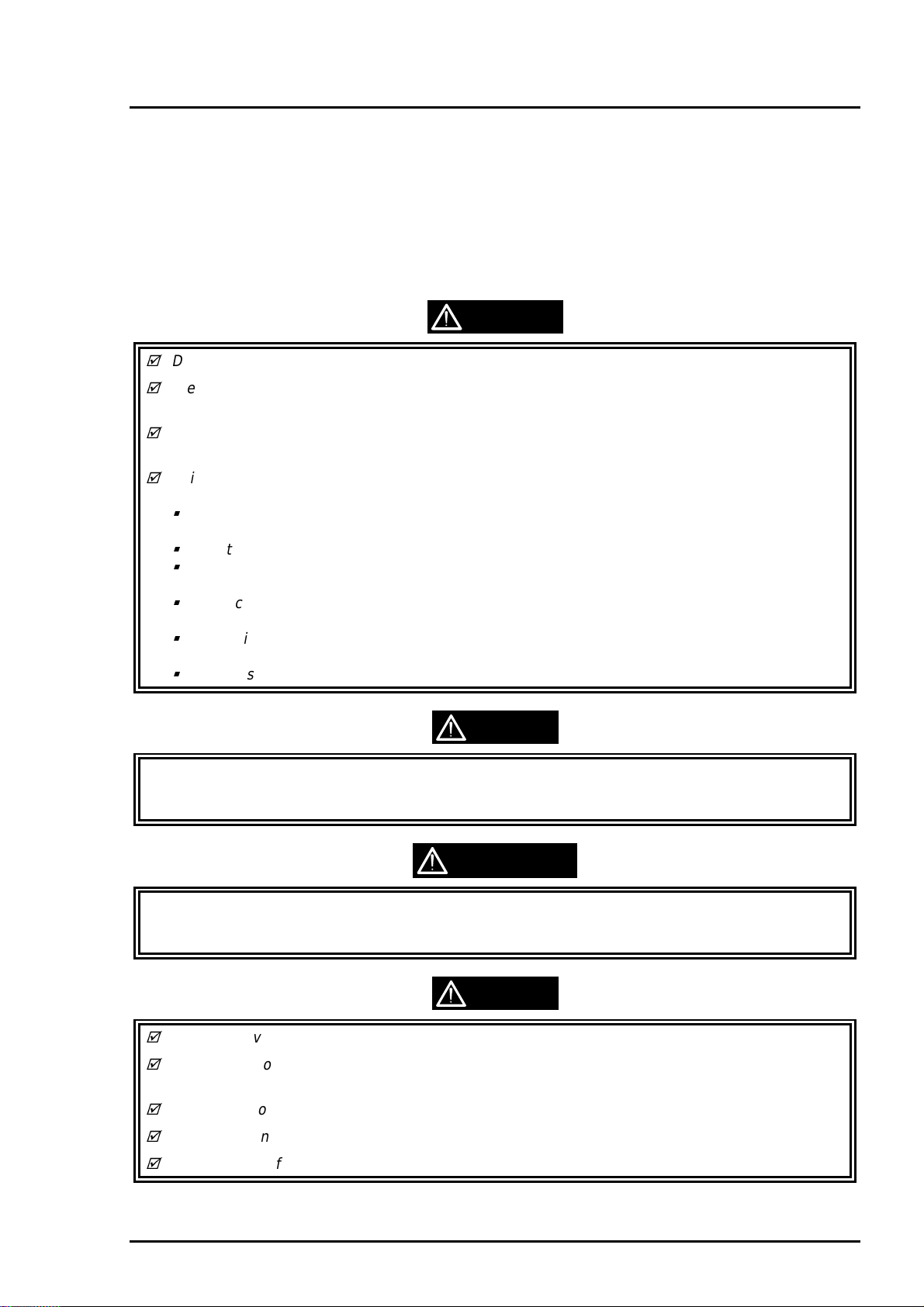
3.1.1 Precautions for Disassembling the Printer
See the precautions below when disassembling or assembling EPSON Stylus Photo.
WARNING
Disconnect the power cable before disassembling or assembling the printer.
Wear protective goggles to protect y our eyes from ink. If ink gets in your eye, flush the eye with
fresh water and see a doctor immediately.
If ink comes into contact with your skin, wash it off with soap and water. If irritation occurs, contact
a physician.
A lithium battery is installed on the main board of this printer. Be sure to observe the following
instructions when servicing the battery:
Keep the battery away from any metal or other batteries so that electrodes of the opposite
polarity do not come in contact with each other.
Do not heat the battery or put it near fire.
Do not solder on any part of the battery. (Doing so may result in leakage of electrolyte from the
battery, burning or explosion. The leakage may affect other devices close to the battery.)
Do not charge the battery. (An explosive may be generated inside the battery, and cause burning
or explosion.)
Do not dismantle the battery. (The gas inside the battery may hurt your throat. Leakage, burning
or explosion may also be resulted.)
Do not install the battery in the wrong direction. (This may cause burning or explosion.)
CAUTION
Danger of explosion if the battery is incorrectly replaced. Replace only with the same or equivalent
type recommended by the manufacture. Dispose the used batteries according to government’s law
and regulations.
Risque d’explosion si la pile est remplacée incorrectment. Ne remplacer que par une pile du même
type ou d’un type équivalent recommandé par le fabricant. Eliminer les piles déchargées s elon les lois
et les règles de sécurité en vigueur.
CAUTION
Never remove the ink cartridge from the carriage unless manual specify to do so.
When transporting the printer after installing the ink cartridge, be sure to pack the printer for
transportation without removing the ink cartridge.
Use only recommended tools for disassembling, assembling or adjusting the printer.
Apply lubricants and adhesives as specified. (See Chapter 6 for details.)
Make the specified adjustments when you disassemble the printer. (See Chapter 4 for details.)
Rev. A
3-1
Page 3
EPSON Stylus Photo
2
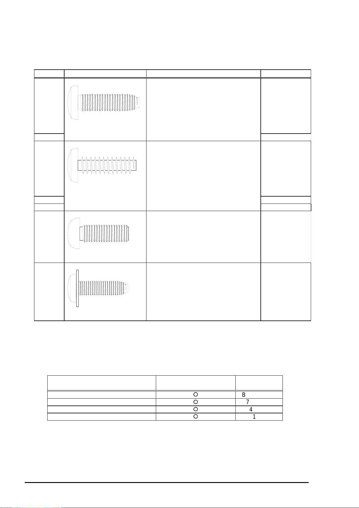
3.1.2 Specification for Screws
Table 3-1 lists the abbreviation of screws and its use. Refer to the screw number in the following table to
identify the type of screw shown in the disassembly procedures.
Table 3-1. Screw Identification Table
No. Shape Name Standard
1 CBS
(Cross/Bind/S-tight screw)
2 M3x10
3 CBP
(Cross/Bind/P-tight screw)
M3x6
M3x6
4 M3x10
5 M3x8
6 CP
(Cross/Pan-head screw)
7 CBS with Washer
(Cross/Bind/S-tight screw with washer)
M3x4
M3x6
3.1.3 Tools
Table 3-2 lists the tools required for disassem bling and ass embling the printer. Use only specified tools to
avoid damaging the printer.
Table 3-2. Required Tools
Name Availability EPSON
Parts Code
Philips Screw Driver (No.1)
Philips Screw Driver (No.2)
Tweezers
Hexagonal Box Driver (5.5mm)
3-
B743800200
B743800400
B741000100
B741700100
Rev. A
Page 4
Chapter 3 Disassembly and Assembly
3
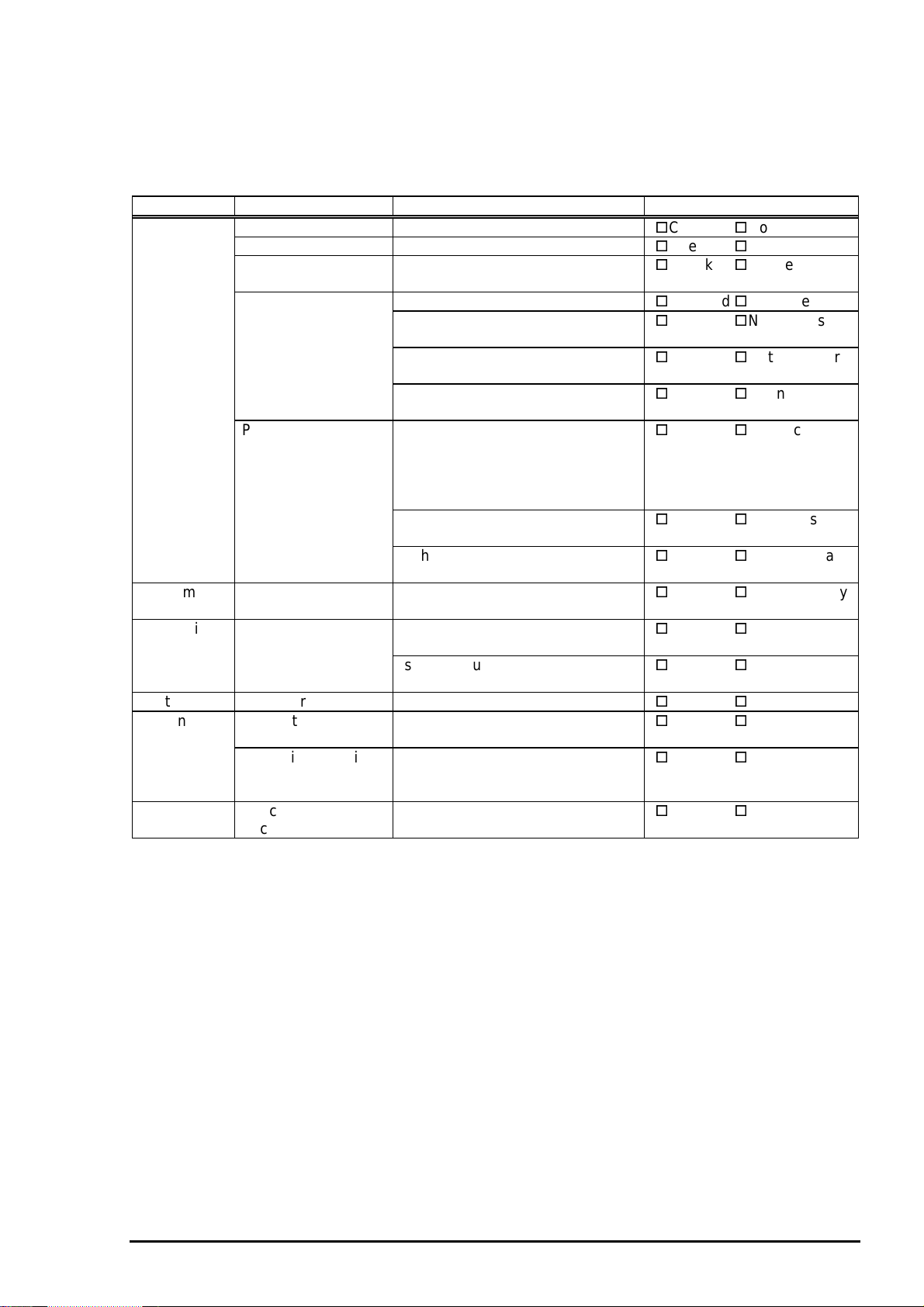
3.1.4 Work Completion Check
If any service is made to the printer, use the check list shown below, to confirm that all works are
completed properly and the printer is ready to return to the user.
Category Item Check Point Status
Main Unit Self-Print Test Is the printing successful?
Online Print Test Is the printing successful?
Printhead Is ink discharged norm ally fr om all
nozzle?
Carriage Mechanism Does it moves smoothly?
Is there any abnormal noise in its
motion?
Is there any dirt or scratch in the
CR guide shaft?
Is the CR Motor at the correct
temperature? (Not too hot)
Paper Feeding
Mechanism
Adjustment Specified
Adjustment
Lubrication Specified Point Does all the lubrication made at
System ROM Version Version (Latest):
Packing Ink Cartridge Are brand-new ink cartridges
Protective Materials Have all relevant protective
Other Attachment,
Accessories
Is paper advanced smoothly?
*No paper jamming
*No paper skew
*No multiple feeding
*No abnormal noise
Is the PF Motor at the correct
temperature? (Not too hot)
Is the paper path clear of all
obstructions?
Are all the adjustments done
correctly?
specified points?
Is the amount of lubrication
correct?
installed correctly?
materials been attached to the
printer?
Have all relevant items been
included in the package?
Checked/Not necessary
Checked/Not necessary
Checked/Not necessary
Checked/Not necessary
Checked/Not necessary
Checked/Not necessary
Checked/Not necessary
Checked/Not necessary
Checked/Not necessary
Checked/Not necessary
Checked/Not necessary
Checked/Not necessary
Checked/Not necessary
Checked/Not necessary
Checked/Not necessary
Checked/Not necessary
Checked/Not necessary
Rev. A
3-
Page 5
EPSON Stylus Photo
4
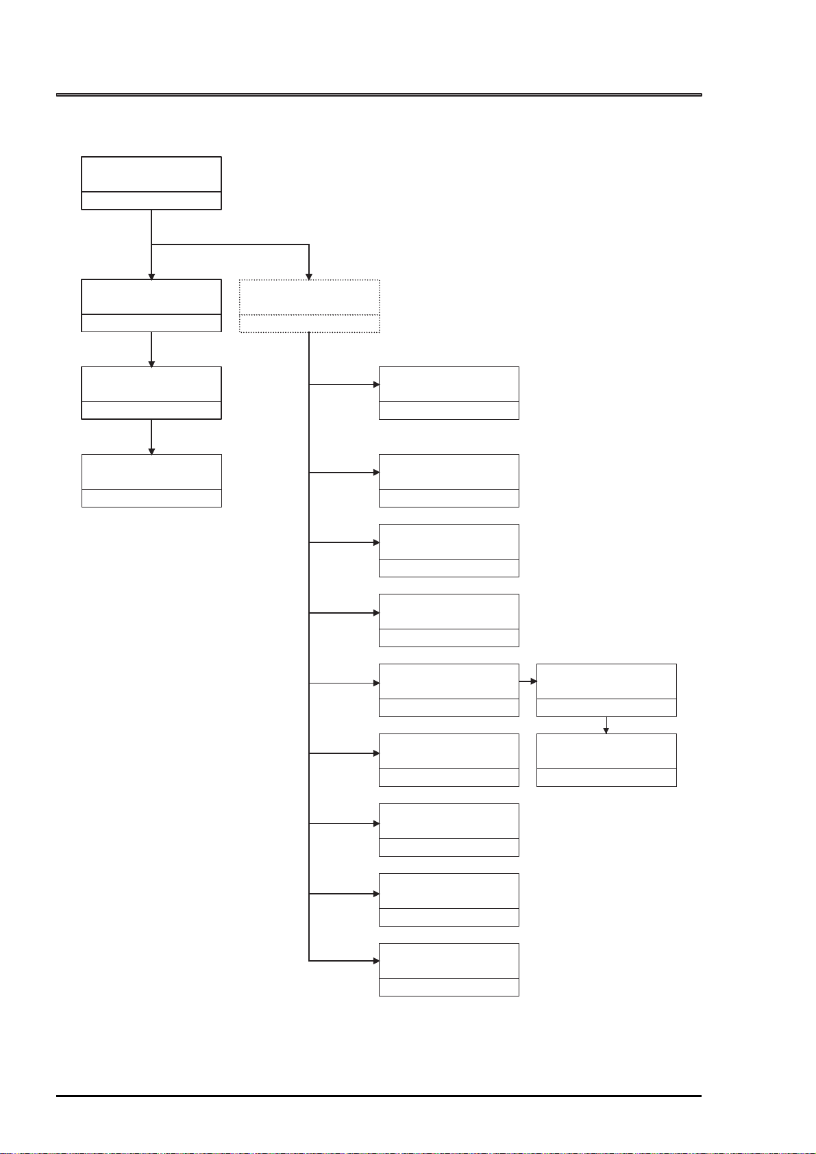
3.2 DISASSEMBLY AND ASSEMBLY
This section describes the step-by-step disassembly procedures shown in the diagram below.
Housing
Removal
Section 3.2.1
Circuit Boards
Removal
Section 3.2.2
Control Panel
Removal
Section 3.2.3
Waste Ink Pad Assembly
Removal
Section 3.2.4
Printer Mechanism
Disassembly
Seciton 3.2.5
Printhead
Removal
Section 3.2.5.1
Pump/Cap Assembly
Removal
Section 3.2.5.2
CR Motor Assembly
Removal
Section 3.2.5.3
PF Motor Assembly
Removal
Section 3.2.5.4
ASF Assembly
Removal
Section 3.2.5.5
ASF
Disassembly
Section 3.2.5.5.1
3-
Carriage Assembly
Removal
Section 3.2.5.6
PF Roller Assembly
Removal
Section 3.2.5.7
PE Sensor Assembly
Removal
Section 3.2.5.8
HP Sensor Assembly
Removal
Section 3.2.5.9
Figure 3-1. Flow Chart of Disassembly
Pick-Up Roller Assembly
Removal
Section 3.2.5.5.2
Rev. A
Page 6
Chapter 3 Disassembly and Assembly
5
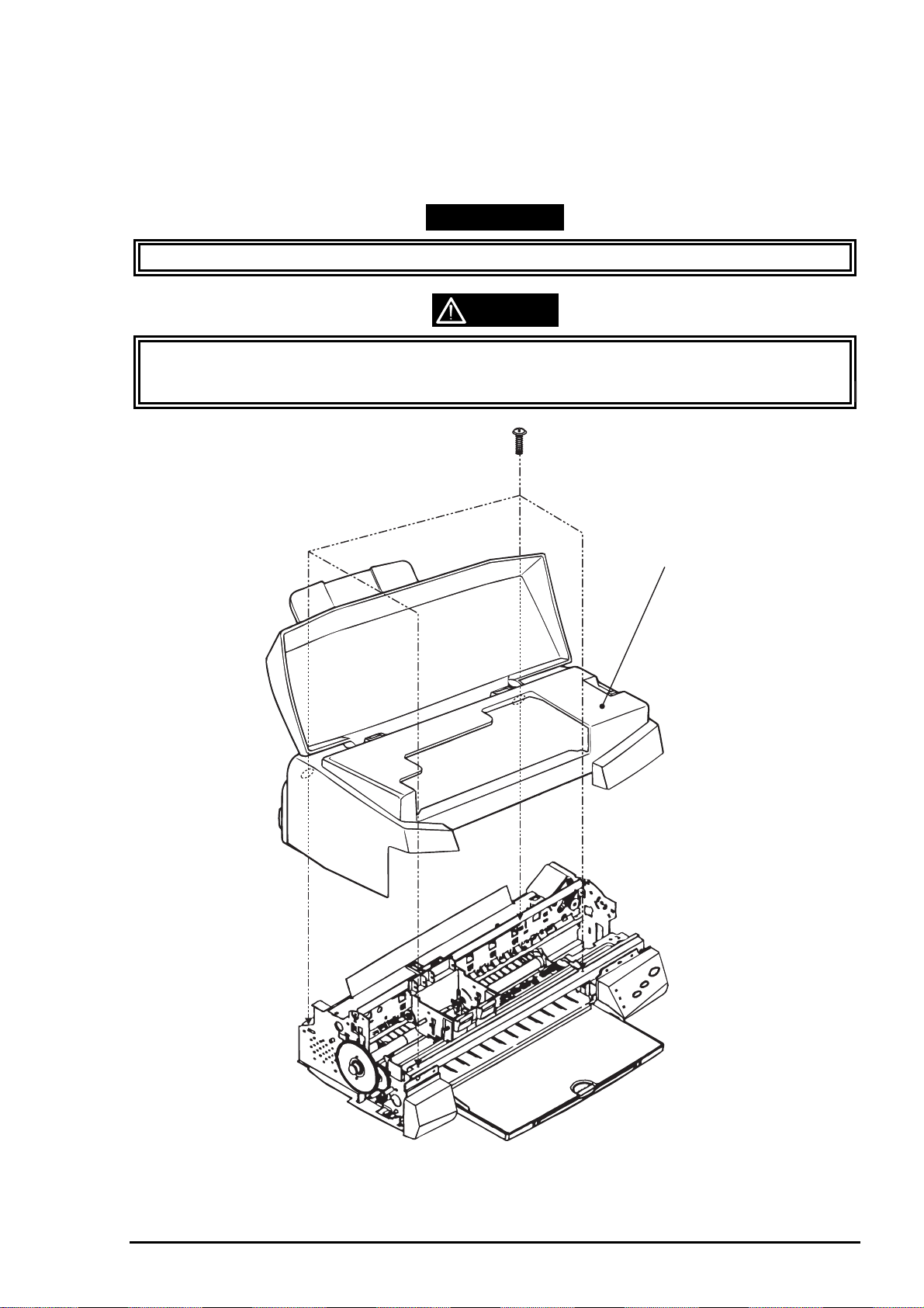
3.2.1 Housing Removal
Since the EPSON Stylus Photo has no lower housing as previous EPSON printers, the printer mechanism
can be taken out by only removing the upper housing.
1. Open the printer cover and set the PG adjust lever on the right-hand side to (+) position.
2. Remove 4 screws (No.2) and remove the upper housing.
WORK POINT
Pull the front end of the upper housing while lifting up the upper housing to remove it.
CAUTION
Be careful not to pinch the cables with the posts of the upper housing when reins talling it. (Espec ially
with the cables from the motors and doing so causes fatal damage to the mechanism and the electric
circuitry.)
Upper Housing
Figure 3-2. Housing Removal
Rev. A
3-
Page 7
EPSON Stylus Photo
6
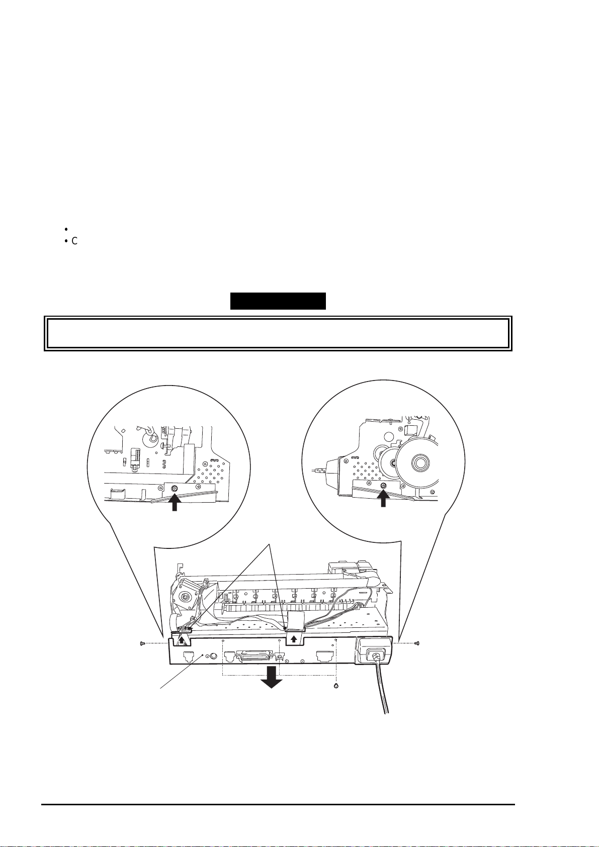
3.2.2 Circuit Boards Removal
The electric circuit boards of the printer (Main control circuit board: C209 MAIN / Power supply circuit
board: C206 PSB/PSE) are both installed on single metal chassis and attached to the printer mechanism.
Therefore, first detach the metal chassis from the printer mechanism to remove the electric circuit boards.
1. Remove the upper housing (Refer to section 3.2.1)
2. Remove 5 screws (No.1 / three at the back of the printer mechanism and one each at both sides
of the printer mechanism)
3. Slightly pull out “SHIELD PLATE, M/B” (metal chassis) from the printer mechanism and take out
the cable holders inserted to the edge of “SHIELD PLATE, M/B”.
4. Fully separate “SHIELD PLATE, M/B” from the printer mechanism and remove all cables
connected to the connectors on the main board; C209 MAIN.
5. If you need further to remove each electric circuit board from “SHIELD PLATE, M/B”, remove the
screws fixing each board and remove the board.
C209 MAIN BOARD: 10 screws (No.1 = 7 screws, No.6 = 3 screws)
C206 PSB/PSE BOARD: 4 screws (No.1)
Also disconnect the cable from the connector; CN10 (locking type) on the C209 MAIN, when you
remove the C206 PSB/PSE BOARD.
WORK POINT
Unlock the connector CN6/7 on the C209 MAIN by pulling its loc k before disconnect the cables, and
be sure to lock it when reconnecting the cables.
[Cable Holders]
SHIELD PLATE, M/B
Figure 3-3. SHIELD PLATE M/B Removal
3-
Rev. A
Page 8
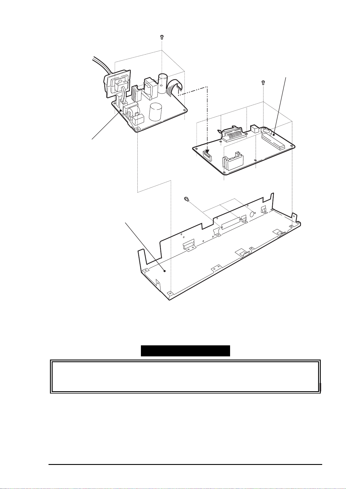
7
Power Supply Board
(C206 PSB/PSE)
Chapter 3 Disassembly and Assembly
MAIN Board
(C209 MAIN)
SHIELD PLATE, M/B
Figure 3-4. Circuit Boards Removal
REQUIRED ADJUSTMENT
Be sure to perform the following adjustments when the C209 MAIN board is replaced:
1) VH Setting (Refer to Chapter 4 / Section 4.2.2.4.)
2) Head Angular Adjustment (Refer to Chapter 4 / Section 4.2.2.5.)
3) Bi-D Alignment Adjustment (Refer to Chapter 4 / Section 4.2.2.6.)
Rev. A
3-
Page 9
EPSON Stylus Photo
8
3.2.3 Control Panel Removal
1. Remove the upper housing (Refer to Section 3.2.1)
2. Remove 2 screws (No.1) and remove the “PANEL, ASSEMBLY” and “HOUSING, PANEL, LEFT” from
the printer mechanism and disconnect the flat cable from the connector of the panel assembly.
WORK POINT
By removing the control panel assembly, the stacker assembly is also detached from the printer
mechanism since it is held by the control panel assembly.
SHIELD PLATE, PANEL
C209 PNL Board
HOUSING, PANEL, LEFT
PANEL, ASSEMBLY
STACKER, ASSEMBLY
Figure 3-5. Control Panel Removal
3-
Rev. A
Page 10

Chapter 3 Disassembly and Assembly
9
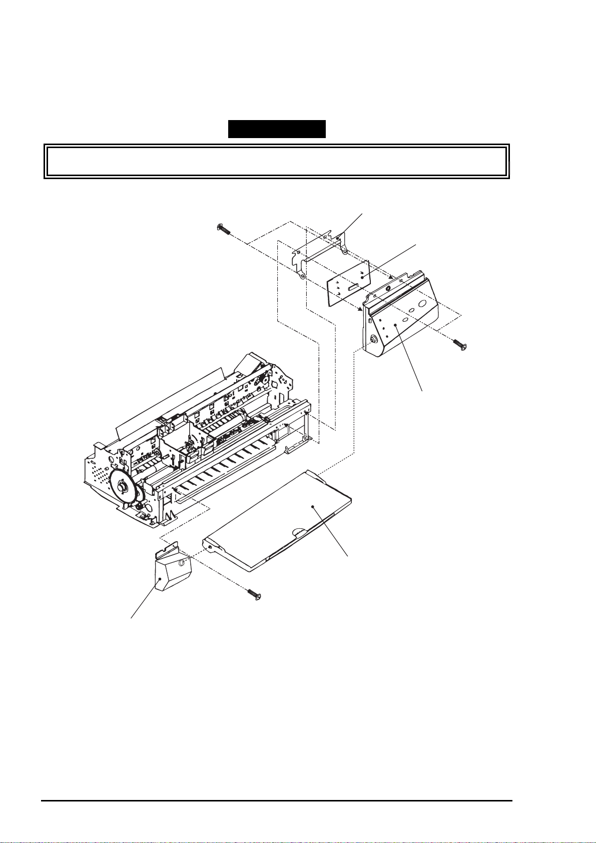
3.2.4 Waste Ink Pad Assembly Removal
1. Removing the upper housing (Refer to section 3.2.1)
2. Removing the control panel assembly (Refer to section 3.2.3)
3. Remove 1 screw (No.4) at the right-hand side of the printer mechanism, that fixing “Waste Ink Pad
Assembly”.
4. Remove “SPACER, TRAY” fixing “Waste Ink Pad Assembly” at the left-hand side of the printer
mechanism and remove “Waste Ink Pad Assembly” by pulling it dow nward.
CAUTION
When you replace “Was te Ink Pad Assembly” to new one, be sure to perform the ink counter reset
operation. (Refer to Chapter 1 / Section 1.4.2 for details)
WORK POINT
When re-installing “Waste Ink Pad Assembly ”, be sure that “Stopper, Stacker” that attached to the exit
roller shaft is correctly pushed in to back of the projections of “Waste Ink Pad Assembly”.
SPACER, TRAY
Section (A)
[Projections]
Paper Exit Roller Shaft
Front side
STOPPER, STACKER
Push it to the back of
projection
Figure 3-6. Waste Ink Pad Assembly Removal
Waste Ink Pad Assembly
Rev. A
3-
Page 11

EPSON Stylus Photo
0
3.2.5 Disassembling the Printer Mechanism
This section describes the procedures for removing the main components consisting the printer
mechanism.
3.2.5.1 Printhead Removal
1. Removing the upper housing. (Refer to section 3.2.1)
2. Rotate “Gear, 67.2” (largest gear at the left-hand side of the printer mechanism) toward the front to
disengage the carriage lock mechanism, and move the carriage assembly to the middle of the printer.
3. Remove both black and color ink cartridges.
4. Remove both carriage cover assemblies from the carriage.
5. Remove “Twist Spring, 49” at left-hand side of the carriage and remove 1 screw (No.3) fixing
“FASTNER, HEAD”. Then, remove “FASTNER, HEAD” from the carriage.
6. Unhook the flat cables from the carriage assembly and tae out the printhead unit from the carriage.
7. Disconnect the cables from the connector of the printhead unit.
WORK POINT
Notice that the grounding plate is installed in correct pos ition. (there are two fixing pins in the
carriage)
Be sure that fixing pin of the carriage is correctly located into the cut out of the printhead unit.
CAUTION
Once the ink cartridge is removed, it is not re-usable and always install brand-new ink cartridge
before returning the printer to the user.
When returning the printer to the user, be sure that the ink cartridge is installed and the carriage
is at the capping position. (Turn the printer off while the carriage is at the capping position and
pack it in that state)
This part should
be touching the
CR axis receiver.
Make sure that this
protrusion is in the
U ditch of the priht head
side.
Make sure that protrusion
of carriage is in the hole
of the earth board.
Carriage Assembly
Print Head
Figure 3-7.Printhead Installation
3-1
Rev. A
Page 12

Printhead Unit
TWIST SPRING, 49
Chapter 3 Disassembly and Assembly
Flat Cable
FASTNER, HEAD
Figure 3-8. Printhead Unit Removal
CAUTION
If you remove the Flat cable from the printer mechanism, make s ure that the Flat cable is fixed to
the frame firmly when assembling.
REQUIRED ADJUSTMENT
When you remove or replace the printhead unit, be sure to perform the following adjustments:
1) Ink Charge Operation (Refer to Chapter 4 / Section 4.2.2.3.)
2) VH Setting (Refer to Chapter 4 / Section 4.2.2.4.)
3) Head Angular Adjustment (Refer to Chapter 4 / Section 4.2.2.5.)
Rev. A
3-1 1
Page 13

EPSON Stylus Photo
2
3.2.5.2 Pump Assembly and Cap Assembly Removal
1. Removing the upper housing. (Refer to Section 3.2.1)
2. Removing the control panel assembly. (Refer to section 3.2.3)
3. Removing “Waste Ink Pad Assembly”. (Refer to section 3.2.4)
4. Loosen 2 screws (No.1) fixing the exit frame assembly and disengage the frame from the side frames.
Then, put the printer mechanism on its back as you can see the bottom of the mechanism.
5. At the right-hand of the mechanism, unhook the cap assembly by releasing one hook and take out the
cap assembly by lifting up the right end of it. (Note that the cap assembly is still connected to the pump
assembly by the ink tube.)
6. Remove 2 screws (No.5) fixing the pump assembly to the frame.
7. Unhook the pump assembly by releasing one hook and slide the pump assembly to the right direction
to remove it.
CAUTION
Be careful not to damage rubber part of the cap assembly. (Damaging the rubber part causes
incomplete capping and the nozzle condition become unstable.)
Be careful with the followings when you handle “CLEANER, HEAD”:
•Do not handle it with bare hands and avoid attaching any oil or dust.
•Make sure that the rubber side of “CLEANER, HEAD” is facing to the right.
WORK POINT
Be careful not to popping the components from the pump assembly when you remove it from the
mechanism, since there is a spring inside the pump assembly.
Be sure that the ink tube from the cap assembly is routed to the correct position and not pinched
by the cap assembly and the frame.
Verify that “CLEANER, HEAD” moves smoothly by rotating “GEAR, 67.2” after you re-assemble
the pump assembly. (Hold the cap assembly to the right direction while you rotating the gear for
check)
Ink Tube Routing
OK
(Ink tube goes behind of
the cap assembly)
Viewed from front
NG
(The ink tube is on the part of
the cap assembly)
Figure 3-9. Ink Tube Routing
3-1
Rev. A
Page 14

3
Loosen screw and
lift up the exit frame
PUMP ASSEMBLY
Chapter 3 Disassembly and Assembly
Unhock the cap assembly
CAP ASSEMBLY
CLEANER, HEAD
Remove 2 screws and unhook the hooks
to remove the pump assembly
Figure 3-10.Cap Assembly Removal
Pump Components
Assembly Order
Figure 3-11.Pump Assembly Removal
Rev. A
3-1
Page 15

EPSON Stylus Photo
4
3.2.5.3 CR Motor Assembly Removal
1. Removing the upper housing. (Refer to section 3.2.1)
2. Rotate “Gear, 67.2” (largest gear at the left-hand side of the printer mechanism) toward the front to
disengage the carriage lock mechanism, and move the carriage assembly to the middle of the printer.
3. Push “HOLDER, PULLEY, DRIVEN” inward to loosen the timing belt and detach the timing belt from
the drive pulley of CR Motor assembly.
4. Remove 2 screws (No.1) and remove “MOTOR, ASSEMBLY, CR” from the mechanism.
WORK POINT
Be sure that the projections of the motor bracket is inserted to the holes of the frame properly.
REQUIRED ADJUSTMENT
When you replace “MOTOR, ASSEMBLY, CR”, be sure to perform the following adjustment:
1) Bi-D Alignment Adjustment (Refer to Chapter 4 / Section 4.2.2.6.)
COMPRESSION SPRING, 19.6 PULLEY, ASSEMLBLY, DRIVEN
Outside side frame
TIMING BELT
Inside side frame
HOLDER, PULLEY, DRIVEN
Figure 3-12. Driven Pulley Removal
3-1
Rev. A
Page 16

Chapter 3 Disassembly and Assembly
5
The projections of motor assembly must
locate inside the holes
Figure 3-13. CR Motor Removal
Rev. A
3-1
Page 17

EPSON Stylus Photo
6
3.2.5.4 PF Motor Assembly Removal
1. Removing the upper housing. (Refer to section 3.2.1)
2. Removing “Waste Ink Pad Assembly”. (Refer to section 3.2.4)
3. By referring the figure below, remove the specified gears from the mechanism:
“GEAR, 67.2”
“COMBINATION GEAR, 8, 14.4”
“COMBINATION GEAR, 8.8, 21.6”
“GEAR, 36”
4. Remove 2 hexagonal lock nuts and remove “MOTOR, ASSEMBLY, PF”.
WORK POINT
When removing the PF Motor, first, slightly pulling out the PF Motor from the frame and slide the
motor shaft to a larger cut out of the frame and remove it.
Be careful with the routing direction of the cable from the PF motor.
COMPRESSION SPRING, 0.9
GEAR, 67.2
MOTOR, ASSEMBLY, PF
Hexagonal Nut
COMBINATION GEAR, 8, 14.4
COMBINATION GEAR, 8.8, 21.6
GEAR, 36
Lock Ring
Figure 3-14. PF Motor Removal
3-1
Rev. A
Page 18

7
MOTOR, ASSEMBLY, PF
(behind the frame)
Cable Direction
Chapter 3 Disassembly and Assembly
Put the motor shaft once in a larger hold
then slide it to a smaller hole
Figure 3-15. PF Motor and Frame
Rev. A
3-1
Page 19

EPSON Stylus Photo
8
3.2.5.5 ASF Assembly Removal
1. Removing the upper housing. (Refer to section 3.2.1)
2. Remove the locking pin from center of “GEAR, 34” and remove “GEAR, 34” from the shaft.
3. Unhook the cables from the cable hook of the ASF and the printer mechanism.
4. Remove 2 screws (Refer to the figures) fixing the ASF and remove the ASF from the mechanism by
detaching the projection of ASF (at left) from the hole of the mechanism.
WORK POINT
Make sure that the ASF is firmly attached to the mechanism.
Use proper type of screw at specified position (viewed from the back of the mechanism):
Right: “SHAFT, FIXING, CR”
Left: Screw - No.7 (CBS with washer)
CAUTION
When re-installing the ASF, be sure that no c ables (except the flat c able to the printhead) are pinched
between the ASF and the frame.
Especially, if the cables from CR/PF Motor is pinched, there is a danger of short-circuit with the frame
and possibly causes hazardous problem like over-heating, burning of components.
3-1
Rev. A
Page 20

9
[CBS with washer]
Chapter 3 Disassembly and Assembly
SHAFT, FIXING, CR
GEAR, 34
The projections of ASF must be
in these holes
Figure 3-16. ASF Assembly Removal
Rev. A
3-1
Page 21

EPSON Stylus Photo
0
3.2.5.5.1 ASF Disassembly
1. Removing the ASF. (Refer to section 3.2.5.5)
2. Remove “TWIST SPRING, 41.2” by unhooking one end from the ASF frame and remove “LEVER,
BRAKE”.
3. Remove “BUSH, FIXING, SHAFT” from the right end of “SHAFT, ROLLER, LD” and remove “LEVER,
HOPPER, RELEASE”.
4. Move the left paper pick-up assembly to the middle of the ASF and remove “BUSH” from the shaft.
5. Push out “SHAFT, ROLLER, LD” to the left and remove “BUSH, FIXING, SHAFT, LEFT” from the leftend of the shaft by unhook it.
6. Unhook the top of “HOPPER, ASSEMBLY” from the both sides of “FRAME, ASF”.
7. Push out “SHAFT, ROLLER, LD” to the right while pulling up “PICKUP, ROLLER ASSEMBLY, RIGHT”
slightly. Then, detach the left end of “SHAFT, ROLLER, LD” from “FRAME, ASF”.
8. Holds “HOPPER, ASSEMBLY” and remove the right cam part of “HOPPER, ASSEMBLY” through the
hole at the right side of “FRAME, ASF”.
To this point, the ASF assembly is disassembled and both left and right “ PICKUP, ROLLER ASSEMBLY”
and “HOPPER, ASSEMBLY” are separated.
WORK POINT
When removing “HOPPER, ASSEMBLY”, be careful that the grease that applied to the cam part
of it, not to attach to the other part of the ASF. If so, wipe it off completely.
Be careful of the direction when you install the “LEVER, HOPPER, RELEASE”.
Make sure that bushes at the both ends of the shaft are firmly attached.
HOPPER, ASSEMBLY
LEVER, BRAKE
TWIST SPRING, 41.2
BUSH, FIXING, SHAFT, LEFT
CAM part
FRAME, ASF
LEVER, HOPPER, RELEASE
BUSH
SHAFT, ROLLER, LD
BUSH, FIXING, SHAFT
Figure 3-17. ASF Disassembly
3-2
Rev. A
Page 22

Chapter 3 Disassembly and Assembly
3.2.5.5.2 Pick-Up Roller Assembly Removal
1. Disassemble the ASF and separate “PICKUP, ROLLER ASSEMBLY” and “HOPPER, ASSEMBLY”.
(Refer to section 3.2.5.5.1)
2. Remove “COMPRESSION SPRING, 1.66” from the back of “HOPPER, ASSEMBLY”.
3. Pull out the right cam part of “HOPPER, ASSEMBLY” though the hole of right frame of “PICKUP,
ROLLER ASSEMBLY, RIGHT”.
<To this point, “HOPPER, ASSEMBLY” and “PICKUP, ROLLER ASSEMBLY” is separated>
4. Unhook “ROLLER ASSEMBLY, LD” from the assembly frame and remove “COVER, ROLLER, LD” by
unhooking it from the assembly frame. Then, remove “ROLLER ASSEMBLY, LD”.
WORK POINT
When you re-assemble, be sure that “ROLLER ASSEMBLY, LD” is hooked to assembly frame
firmly.
Before re-assemble the unit, make sure that “COMPRESSION SPRING, 1.66” is set on the
assembly frame and hooked to the hooks as shown in the figure. This helps you easier
assembly. After assemble the unit, do not forget to unhook the springs by rotating the spring
from the holes located at the back of the ASF assembly.
COVER, ROLLER, LD (L/R)
+
HOLDER, SHEET, PF
ROLLER, ASSEMBLY, LD (L/R)
COMPRESSION SPRING, 1.66
ASSEMBLY FRAME
Rev. A
Set the spring and hook it
to the assembly frame as
illustrated, before re-assembly
Figure 3-18. Pick-Up Roller Removal
3-21
Page 23

EPSON Stylus Photo
2
3.2.5.6 Carriage Assembly Removal
1. Removing the upper housing. (Refer to section 3.2.1)
2. Push “HOLDER, PULLEY, DRIVEN” inward to loosen the timing belt and detach the timing belt from
the drive pulley of CR Motor assembly.
3. Take out “COMPRESSION SPRING, 19.6” from “HOLDER, PULLEY, DRIVEN”.
4. Remove “PULLEY, ASSEMBLY, DRIVEN” and the timing belt together from “HOLDER, PULLEY,
DRIVEN” and remove “HOLDER, PULLEY, DRIVEN” from the mechanism.
5. Unhook “LEVER, PG” and remove it.
6. Unhook “LEVER, PG, SUB” and remove “LEVER, PG, SUB” and a spring washer from the end of
“SHAFT, CR, GUIDE”.
7. Remove 1 screw (No.7) and rotating “BUSH, PARALLEL ADJUST, RIGHT” to match it with the cut out
of the frame. Then, take out “BUSH, PARALLEL, ADJUST, RIGHT”.
8. Remove “CARRIAGE, ASSEMBLY” together with “SHAFT, CR, GUIDE”.
WORK POINT
It is good idea to mark the current position of “BUSH, PARALLEL ADJUST, RIGHT” before
removal. This enables you to omit the paper gap adjustment after the assembly.
Be careful with the direction of spring washer at the assembly. (A convex side must face the
bush)
REQUIRED ADJUSTMENT
When you remove or replace the carriage assembly, be sure to perform the following adjustments:
1) Paper Gap Adjustment (Refer to Chapter 4 / Section 4.2.1.)
2) Head Angular Adjustment (Refer to Chapter 4 / Section 4.2.2.5.)
3) Bi-D Alignment Adjustment (Refer to Chapter 4 / Section 4.2.2.6.)
BUSH, PARALLEL ADJUST, RIGHT
BUSH, PARALLEL ADJUST, RIGHT
Side frame of
printer mechanism
Figure 3-19. BUSH PARALLEL ADJUS T Removal
3-2
Cut out of side frame
Rev. A
Page 24

3
BUSH, PARALLEL ADJUST, LEFT
Chapter 3 Disassembly and Assembly
Carriage Assembly
SHAFT, CR, GUIDE
Spring Washer
(Convex side must be facing the bush)
Figure 3-20. Carriage Assembly Removal
BUSH, PARALLEL ADJUST, RIGHT
LEVER, PG, SUB
Rev. A
3-2
Page 25

EPSON Stylus Photo
4
3.2.5.7 PF Roller Assembly Removal
1. Removing the upper housing. (Refer to section 3.2.1)
2. Removing the carriage assembly (Refer to section 3.2.5.6)
3. Remove 2 screws (No.1) at the top of mechanism and remove “GUIDE PLATE, CABLE”.
4. From the back of the mechanism, unhook the springs from the frame and remove “PAPER GUIDE,
ASSEMBLY, UPPER” (total 6 pieces).
5. Unhook “PAPER GUIDE, FRONT;B” and remove it.
6. Unhook the both shaft holders of “ROLLER, ASSEMBLY, PAPER EXIT” and remove it.
7. Unhook the left shaft holder of “ROLLER, ASSEMBLY, PF” and rotate it as to match with the cut out of
the frame.
8. Slide “ROLLER, ASSEMBLY, PF” to the left and pulling it out.
WORK POINT
When reinstalling “PAPER GUIDE, ASSEMBLY, UPPER” at right-most position (viewed from the
front), be careful with the detection lever of the PE sensor.
Be careful not to damage the hook of “PAPER GUIDE, FRONT;B” during disassembly and
assembly.
Be careful not to damage the black coated part of “ROLLER, ASSEMBLY, PF” during
disassembly and assembly.
Be careful not to damage the gears.
PAPER GUIDE, LEFT
GUIDE PLATE, CABLE
PAPER GUIDE, ASSEMBLY, UPPER
SHAFT, PAPER GUIDE, UPPER
TWIST SPRING, 117.6
(6 pieces)
Figure 3-21. PAPER GUIDE ASSEMBLY Removal
3-2
Rev. A
Page 26

5
PAPER GUIDE, LEFT
GUIDE PLATE, CABLE
Chapter 3 Disassembly and Assembly
PAPER GUIDE, ASSEMBLY, UPPER
SHAFT, PAPER GUIDE, UPPER
TWIST SPRING, 117.6
(6 pieces)
Figure 3-22. ROLLER, ASSEMBLY, PAPER EXIT Removal
ROLLER, ASSEMBLY, PAPER EXIT
PAPER GUIDE, FRONT;B
Figure 3-23. ROLLER, ASSEMBLY, PF Removal
Rev. A
3-2
Page 27

EPSON Stylus Photo
6
3.2.5.8 PE Sensor Assembly Removal
1. Removing the upper housing. (Refer to section 3.2.1)
2. From the front side of the mechanism, unhook two hooks fixing “SENSOR, ASSEMBLY, PE” to the
mechanism. Then, slide it to upward to remove it. After removal, disassemble the assembly if
necessary.
WORK POINT
When re-install the assembly, be sure that the sensor lever is corr ectly insert ed into a hole of “PAPER
GUIDE, ASSEMBLY”, UPPER”.
Release these hooks to
remove the PE Sensor Assembly
From the back side of
the mechanism
HOLDER, PE
To frame
BOARD ASSY., PE
LEVER, PE
Figure 3-24.PE Sensor Assembly Removal
CAUTION
Be careful not to damage the cable when inserting or pulling out it from the PE sensor board.
Make sure the sensor lever moves smoothly when installing it.
3-2
Rev. A
Page 28

Chapter 3 Disassembly and Assembly
7
3.2.5.9 HP Sensor Assembly Removal
1. Removing the upper housing. (Refer to section 3.2.1)
2. Detach the cable from the sensor and remove it by unhook it from the frame.
SENSOR, HP
CR MOTOR
Figure 3-25. HP Sensor Removal
CAUTION
Make sure that the sensor itself is attached firmly to the frame when installing the HP sensor
again.
Be careful not to damage the sensor board when installing or pulling out the cable from the HP
sensor.
Rev. A
3-2
 Loading...