

Page 1

Chapter 5
Troubleshooting
5.1 Troubleshooting....................................................................................................5-1
5.2 Unit Level Troubleshooting .................................................................................5-3
5.2.1 Printer does not operate at power on................................................................................... 5-4
5.2.2 Error is detected.....................................................................................................................5-5
5.2.3 Failure occurs during printing .............................................................................................. 5-6
5.2.4 Printer does not feed the paper correctly............................................................................5-7
5.2.5 Control panel operation is abnormal.................................................................................... 5-8
5.3 Unit Repair C206 PSB/PSE Board.......................................................................5-9
5.3.1 Unit Repair - C209 MAIN Board........................................................................................... 5-11
5.4 Repair of the Printer Mechanism.......................................................................5-13
Page 2
EPSON Stylus Photo
5.1 Troubleshooting
The printer may exhibit different symptoms for the same problem, which makes troubleshooting more
difficult. This section, however, provides simple and effective ways to facilitate troubleshooting.
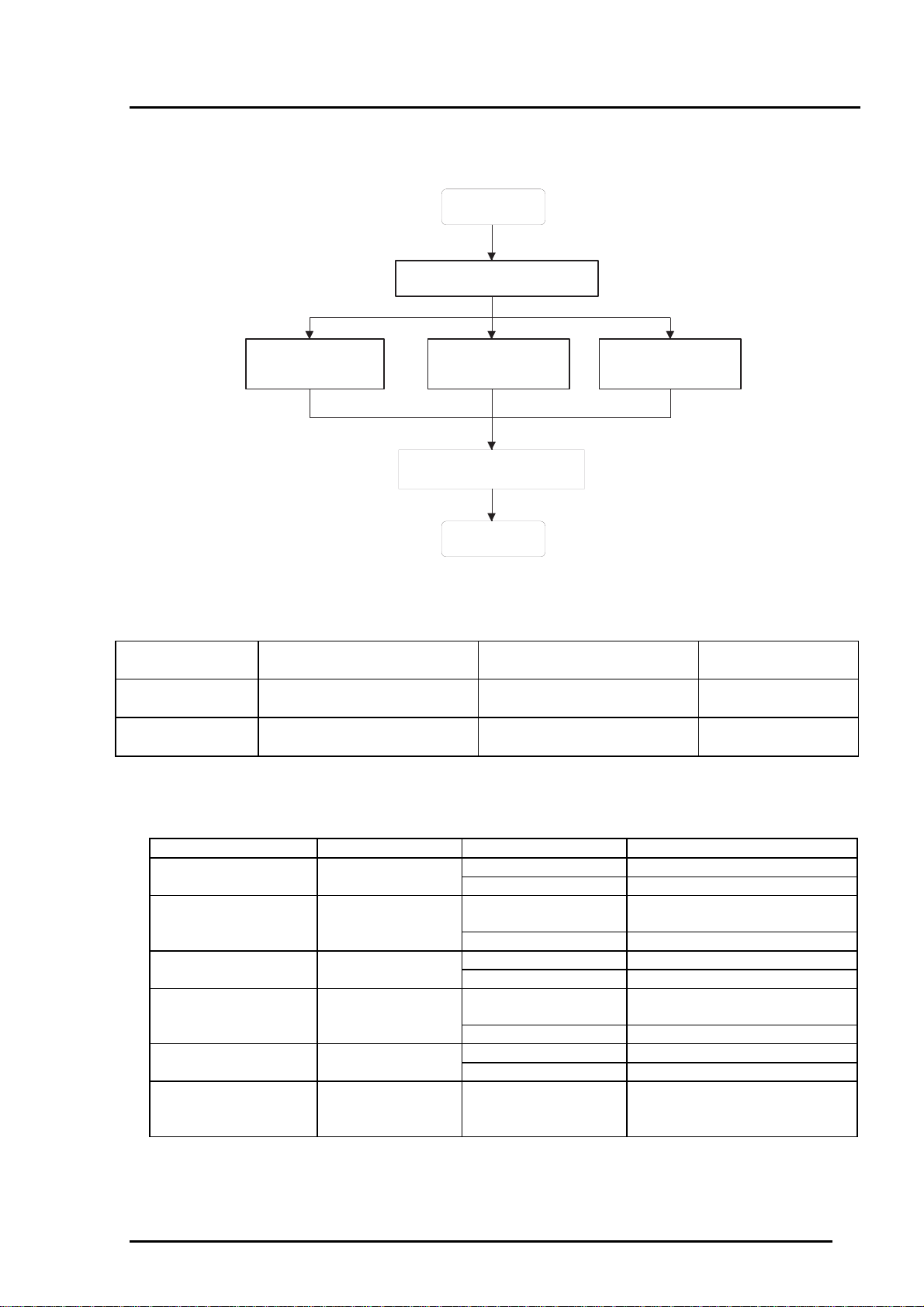
The following flowchart illustrates the main steps of the troubleshooting process.
START
Unit Level Troubleshooting
Unit Repair
(C206 PSB/PSE)
Unit Repair
(C209 Main)
Disassembly and Adjustment
END
Unit Repair
Printer Mechanism
Figure 5-1. Troubleshooting Process Flowchart
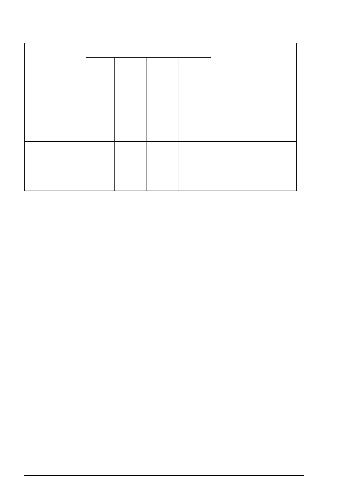
Table 5-1. Motor Resistance and Measurement Procedure
Motor Name Location Check Point No.* Meter Reading
CR Motor
Assembly
PF(Pump) Motor
Assembly
Note*)
Set the Multi-meter for measuring resistance range.
CN6(C209 MAIN) 1 & 3pin or,
2 & 4pin
CN7(C209 MAIN) 1 & 3pin or,
2 & 4pin
7.8 Ohms ±10%
(25 °C)
7.8 Ohms ±10%
(25 °C)
Make sure the power is off and remove the motor connectors from the main board.
Table 5-2. Sensor Check
Sensor Name Check Point Signal Level Sensor Status
Paper end sensor CN4 / 1-pin, H (5V) No paper
L (GND) Paper in
Carriage home
CN5 / 1-pin, H (5V) Home position
position sensor
(HP sensor) L (GND) Out of home position
ASF phase Sensor CN11 / 1-pin, H (5V) Friction(paper feeding) position
L (GND) Release(waiting) position
Black cartridge
CN8 / 1-pin, H (5V) Black ink cartridge out
sensor
L (GND) Black ink cartridge exists
Color cartridge sensor CN8 / 2-pin, H (5V) Color ink cartridge out
L (GND) Color ink cartridge exists
Thermistor CN8 / 3-pin, Resistance value It changes according to the
peripheral temperature.
(10KOhms ±1% at 25°C)
Rev. A
5-1
Page 3
Chapter 5 Troubleshooting
Table 5-3. Printer Condition and Panel Status
Indicators
Error status
Power Ink Out
(Black)
Paper Out --- --- --- On Load paper then press
Paper jam condition --- Off Off Blink Eliminate a paper then press
No Ink cartridge or Ink
end(black)
No Ink cartridge or Ink
end(color)
Ink low (Black) --- Blink --- --- ---
Ink low (Color) --- --- Blink --- --Maintenance error Blink Blink Blink Blink Change the waste ink absorber
Fatal error Blink On On Blink Turn off the printer and turn it
--- On --- --- Install a new black ink cartridge
--- --- On --- Install a new color ink cartridge
Ink Out
(Color)
Paper Out
load/eject button.
load/eject button.
according to ink cartridge
exchange operation.
according to ink cartridge
exchange operation.
and reset the protect counter.
on again. If the printer can not
recover, repair the suitable part.
Recovery
5-2
Rev.A
Page 4
EPSON Stylus Photo
5.2 Unit Level Troubleshooting
When a problem occurs, you can identify the defective unit according to the symptoms exhibited.
The table below lists the symptoms of certain problems. Once the problem is identified, refer to the
flowchart that corresponds to the problem.
Table 5-4. Symptom and Problem
Symptom Problem Flowchart No.
Printer does not operate at
power on
Error is detected
Failure occurs during printing
Printer does not feed the paper
correctly
Control panel operation is
abnormal
•
LEDs do not light up.
•
Printer mechanism does not operate.
•
Error is indicated by LED indication.
•
Printing is not performed.
•
Abnormal printing(missing dot, etc.)
•
Print quality is poor
•
No paper is fed.
•
Paper feed is irregular.
•
Paper jam occurs.
•
No response to button access.
1
2
3
4
5
Rev. A
5-3
Page 5
Chapter 5 Troubleshooting
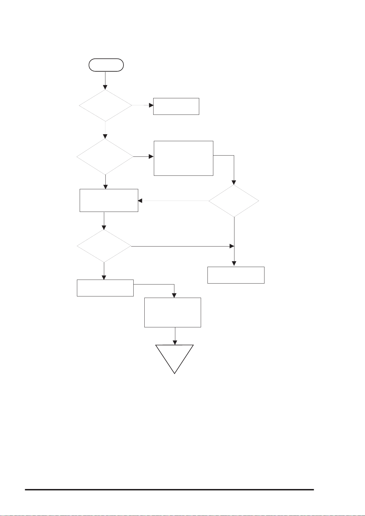
5.2.1 Printer does not operate at power on
START
Is AC
power voltage
normal?
YES
Is the
fuse(F1) of
power supply
board
opened?
NO
Check output voltage
of CN2 in the power
supply board.
Is the
output voltage
of power supply
normal?
YES
Exchange the main
board.
NO
NO
YES
Input normal
power supply.
Exchange the fuse.
Disconnect CN10 in
the main board and
turn the power on
again.
NO
Is the
fuse opend
again?
YES
Exchange the power
supply board
Check the motor and
head. Refer to the
repair item of the
printer mechanism.
END
Figure 5-2. Flow Chart 1
5-4
Rev.A
Page 6

EPSON Stylus Photo
5.2.2 Error is detected
START
Check the error
message.(Refer to
Table5-3)
Is it carriage
error?
NO
No ink cartridge
error?
NO
Maintenance Error
Exchange the waste
ink absorber and reset
the counter.
(Refer to 1.4.2)
Check ink cartridge
sensor and exchange
the head if it's ubnormal.
Yes
Yes
Turn off the printer,
and move the carriage
by hand.
Exchange the inkcartridge with new
one.
Yes
Does error
appear again?
NO
Does the carriage
move smoothly?
Yes
Check CR motor.
Exchange the main
board if there is no
problem.
Yes
Is the problem
solved?
NO
Refer to 5.4
Repair of the printer
mechanism.
NO
Rev. A
END
Figure 5-3. Flow Chart 2
END
5-5
Page 7

Chapter 5 Troubleshooting
5.2.3 Failure occurs during printing
START
Perform selftest printing
Is printing
carried out
O.K?
YES
Is printing
quality
normal?
NO
Perform cleaning
NO
Perform printing
adjustment.
YES
(Refer to Chapter4)
Is all
cables connected
to the main
board?
NO
Connect cables
YES
problem
solved?
YES
Is the
END
Exchange the ink
cartridge with new
one and perform
NO
self-test.
Is the
problem
YES
YES
solved?
NO
Refer to 5.4 Repair of
the printer-mechanism.
Is the
problem
solved?
NO
END
Is the
problem
solved?
YES
Replace the Main
board
Refer to 5.4 Repair of
the printer-mechanism.
NO
Is the
problem
NO
solved?
END
YES
5-6
Figure 5-4.Flow Chart 3
Rev.A
Page 8

EPSON Stylus Photo
5.2.4 Printer does not feed the paper correctly
START
Are
papers set
in the ASF
correctly?
YES
NO
Set the paper correctly
Does
the PF roller
and platen
rotate?
YES
Remove any obstruction
in the paper path if
there is any.
Perform cleaning for
the roller of paper path.
Is the
problem
solved?
YES
NO
NO
Is the
PF motor
running?
YES
Refer to 5.4.Repair
of the printer
mechanism.
NO
Check the PF motor.
If there is no problem,
replace the main board.
Rev. A
END
END
Figure 5-5. Flow Chart 4
5-7
Page 9

Chapter 5 Troubleshooting
5.2.5 Control panel operation i s abnor mal
START
Is the
control panel
connected
correctly?
NO
YES
Replace the control
panel.
Is the
problem
solved?
YES
Connect the
control panel
correctly.
Is the
problem
solved?
YES
NO
NO
Replace the
main board.
5-8
END
Figure 5-6. Flow Chart 5
END
Rev.A
Page 10

EPSON Stylus Photo
5.3 Unit Repair C206 PSB/PSE Board
This section describes the problems related to the power supply board(C206 PSB/PSE). The table below
provides various symptoms, likely causes, and checkpoints. The checkpoints refer to waveforms,
resistance, and other values to be checked to evaluate the operation of each component.
Table 5-5. C206PS B Power Supply Borad
Symptom Condition Cause Checkpoint Solution
The printer
does not
operate at all.
+42V line is
dead.
F1 is open. Check F1 by using a
tester.
Replace F1.
Transformer coils
are open.
Switching FET (Q1)
is dead.
Feed back
transistor(Q2, Q3)
are dead.
+42 V line is
abnormal.
Check the waveform at
the drain of Q1.
Check drain side. Replace Q1.
Check corrector side.
Check following parts.
• ZD87,ZD83
• ZD51,ZD81•`ZD86
• PC1
Replace T1.
Replace Q2
or Q3.
Replace
suitable
parts.
Rev. A
5-9
Page 11

Chapter 5 Troubleshooting
Table 5-6. C206PSB Power Supply Board (Continued)
Symptom Condition Cause Checkpoint Solution
+5V line is
dead.
IC51 (L4962E) is
dead.
Check the oscillation(5
-pin) and switching (7pin) waveform of IC51.
(5-pin)
(7-pin)
Replace
IC51.
5-10
Rev.A
Page 12

EPSON Stylus Photo
5.3.1 Unit Repair C209 MAIN Board
This section describes the problems related to the main controller board(C209 MAIN). The table below
provides various symptoms, likely causes, and checkpoints. The check points refer to waveforms,
resistance, and other values to be checked to evaluate the operation of each component.
Table 5-7. Repair of the C209 MAIN Board
Symptom Condition Cause Checkpoint Solution
The printer
does not
operate at all.
CPU does
not operate.
The reset
circuit is
defective.
Check the waveform of
the +5V and /Reset signal
(IC8=5,1-pin)
Replace IC8
The carriage
does not
operate
normally.
Carriage
motor does
not operate
at all.
Control ROM is
not selected
correctly or it’s
dead.
RAM is
defective.
CPU is
defective.
IC2 is defective. Check the signal
Check if the signal
waveform at 11 pin of the
IC3 can be reversed High
or Low.
Check the clock waveform
at 27 or 28-pin of IC1.
waveform at 1, 2, 23 and
24 pin of IC14.
Replace IC3.
Replace RAM.
Replace IC1 if
the oscillation
waveform is
normal, if it is
abnormal,
replace the
oscillator CR1.
Replace IC2.
Rev. A
IC14 is
defective.
Check the signal
waveform at 3, 6,or 18, 21
pin of IC14.
Replace IC14.
5-11
Page 13

Chapter 5 Troubleshooting
Table 5-8.Repair of the C209 MAIN Board (Continued)
Symptom Condition Cause Checkpoint Solution
Printing is
abnormal
Printing is not
executed or,
black specks or
dots appears on
the printing.
IC2 is defective. Check the output
waveform at 7, 9 and 11
pin of CN8.
Replace IC2.
Paper feed
operation is
abnormal.
Paper feed
motor does not
work.
IC2 is defective. Check the output
waveform of at 1, 2pin
and 23, 24 pin of IC15.
IC15 is defective. Check the output
waveform of at 3, 6 pin
or 18, 21 pin of IC15.
Replace IC2
Replace IC15
5-12
Rev.A
Page 14

EPSON Stylus Photo
5.4 Repair of the Printer Mechanism
This section provides instruction for repairing the printer mechanism. It describes various problems,
symptom, likely causes, checkpoints, and solutions. Select appropriate symptom from the table and
check each parts and its function as described in the checkpoint.
Table 5-9. Repair of the Printer Mechanism
Symptom Condition Cause Checkpoint Solution
Abnormal pump
mechanism
operation
Ink is not
absorbed
or is poorly
absorbed.
Abnormal carriage
operation.
Printing is not
performed.
Abnormal PF
motor operation
when the
power is turned
on.
Used ink does not
go through the
waste ink tube.
Abnormal carriage
operation at power
on.
Abnormal carriage
operation during
printing.
The carriage
moves, but no
printing is
performed.
Foreign substances
are loaded in the PF
gears.
The PF motor is
defective.
(Refer to Table5-1)
The pump tube is
crashed.
Capping rubber is
damaged or
deformed.
The tube is out of
the cap.
Pump bulb is not
closed at
absorption.
Foreign substance
in the CR drive
gear.
CR motor is
defective.
Carriage movement
is not smooth.
Head FFC is out of
connection.
The FFC is
disconnected
inside.
I/C is defective. Install a new I/C and
Head unit is
defective.
Manually drive the
PF drive gear
and check if it
rotates normally .
Check the inner coil
resistance and see
if there is any
disconnection of the coil.
Check the tube
visually.
Check the capping
rubber visually.
Check if the tube is out of
the cap visually.
Check the bulb
operation visually.
Check visually if
there is any
substances or not.
Check the inner coil
resistance and see
if there is any
disconnection of the coil.
Check whether the
carriage moves
smoothly when
moved manually.
Check tension of the
timing belt.
Check if there is any
foreign substances
in the carriage path.
Check if the head
FFC on the board or
carriage is connected
surely.
Check the FFC by using
a tester.
perform the self-test.
If the condition does
not improve even
after 2or 3 times
cleaning operation,
replace the head
unit and perform the
self-test.
Remove any foreign
objects.
Exchange the PF
motor.
Fix the crashed part
by the airgun.
Replace the cap
mechanism.
Connect the tube
properly.
Replace the cap
mechanism.
Remove any foreign
substances.
Replace the CR
motor.
Clean and lubricate
the carriage guide
axis.
Adjust tension
mechanism or
exchange it.
Remove any foreign
substances.
Connect the FFC
properly.
Replace the FFC.
Replace I/C.
Replace the head
unit.
Rev. A
5-13
Page 15

Chapter 5 Troubleshooting
Table 5-10. Repair of the Printer Mechanism (Continued.)
Symptom Condition Cause Check-point Solution
Abnormal printing Only a particular dot
causes abnormal
printing.
A dot is not printed
occasionally.
Black specks or
dots.
A vertical line is not
aligned.
White line appears
in the image data.
Print head surface is
not clean.
(dot missing)
The head unit is
defective.
Absorber in the cap
is touching the head
surface.
Print head surface
is not clean.
(dot-missing)
The head FFC is
disconnected inside.
The head FFC is out
of connection.
The head unit is
detective.
I/C is defective. Install the new I/C
The head FFC is out
of connection.
The head unit is
detective.
Bi-directional
alignment is not
adjusted.
Head angle is not
correct.
Paper feed assembly
adjustment is not
correct.
Perform the cleaning
operation several
times and check
printing.
Perform the cleaning
operation several
times and check
printing.
Check the absorber
in the cap visually.
Perform the cleaning
operation several
times and check
printing.
Check the FFC by
using a tester.
Check if the head
FFC on the board or
carriage is
connected surely.
Perform the cleaning
operation several
times and check
printing.
and perform selftest.
Check if the head
FFC on the board or
carriage is
connected surely.
Check connection
with the head FFC.
Perform Bi-D
adjustment.
Perform head angle
adjustment.
Perform paper feed
assembly
adjustment
Perform the
cleaning.
If condition does not
improve even after
the cleaning, replace
the head.
Replace the
absorber in the cap if
it is deformed.
Perform the
cleaning.
Replace the head
FFC.
Connect the FFC
properly.
If condition does not
improve even after
the cleaning, replace
the head.
Replace I/C.
Connect the FFC
properly.
Replace the head if
there is no
connection problem
with the FFC.
Refer to Chapter4.
Refer to Chapter4.
Refer to Chapter4.
5-14
Dot shooting
direction is tilted
because head
surface is not clean
I/C is defective. Install a new I/C and
Head unit is
defective.
Perform the cleaning
operation several
times and check
printing.
perform the self-test.
Perform the cleaning
operation several
times and check
printing.
Perform the
cleaning operation.
Replace I/C.
Replace the head
unit.
Rev.A
Page 16

EPSON Stylus Photo
Table 5-11. Repair of the Printer Mechanism (Continued)
Symptom Condition Causes Checkpoint Solution
Abnormal paper
feeding.
Printer stops during
initialization.
Paper is not fed. Friction of the PF
roller.
Abnormal operation
of the hopper.
Malfunction of ASF
drive change-over.
Printing start point is
not right.
Fatal error appears. ASF sensor is
Friction of the PF
roller.
defective.
PE sensor is
defective.
HP sensor is
defective.
Head FFC is
disconnected.
Check if the PF
roller rotates when
paper is not fed.
Check movement of
the ASF hopper
visually.
Check if the ASF
gear rotates visually.
Check if the PF
roller slips during
paper feeding.
Check the signal
level of the ASF
sensor.(Refer to
Table 5-2)
Check the signal
level of the PE
sensor.(Refer to
Table 5-2)
Check the signal
level of the HP
sensor .(Refer to
Table 5-2.)
Check if the head
FFC is connected.
Clean the PF roller
by the cleaning
sheet. Replace the
PF roller if it does
not recover.
Replace ASF.
Replace gears of
the ASF drive
change-over.
Clean the PF roller
by the cleaning
sheet. Replace the
PF roller if it does
not recover.
Replace ASF
sensor.
Replace PE sensor.
Connect the head
FFC.
CR motor is
defective.
PF motor is
defective.
Check the CR motor
cable is connected.
Check if the PF
motor cable is
connected.
Replace the CR
motor if there is no
problem in the cable
connection.
Replace the PF
motor if there is no
problem in the cable
connection.
Rev. A
5-15
 Loading...