

Page 1
Instructional Manual Continuous Ink System for use in Epson Stylus Photo R290 Printer
Before using this product, please read and follow the instructions carefully.
Conduct Parts Check:
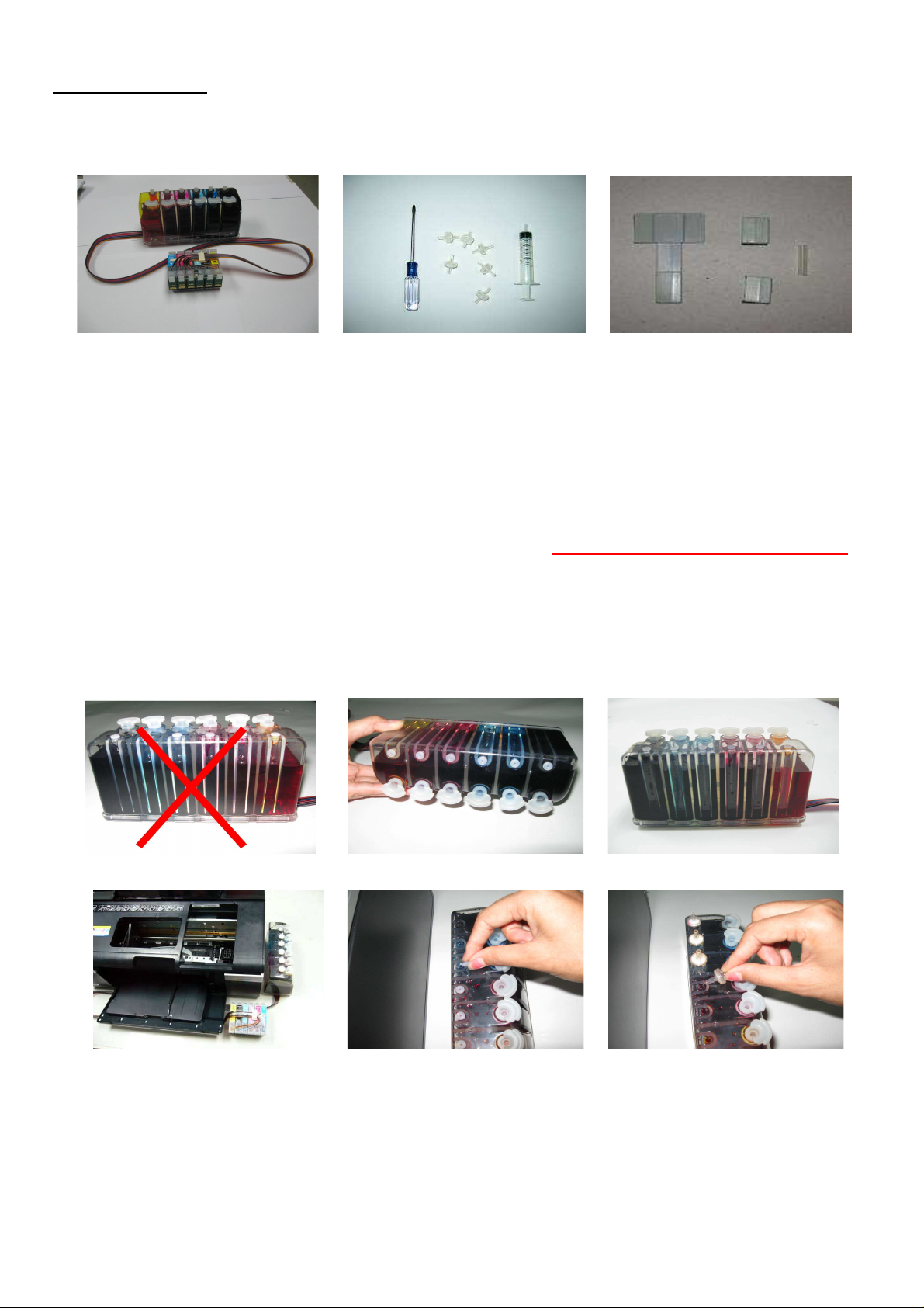
1. Accessories
a. Continuous Ink System (1) b. Air breather plugs (6) & Syringe (1) &Screwdriver (1)
c. T shape Adhesive Pad (1) & square adhesive pad (2) d. Plastic tube (1)
Fig. 1-1 Fig. 1-2 Fig.1-3
2. Set-Up Continuous Ink System (CIS)
a. Before installation, lay out all your parts in front of your printer .
b. Check your system for any leakage, and make sure your tubing system is tightly connected and straight.
c. Place the CIS ink tank on the same horizontal level as printer, The ink tank has two chambers per color, the front
chamber is to hold the ink and the rear chamber is to control the flowing pressure. It is important that the rear chamber
contains only a small amount of inks(as little as possible). The ink should reside in the front chamber. Make sure the ink
tank plugs are tightly closed, tilt the ink tank forward to make the majority of the ink flow into the front chamber if the
rear chamber has some excess ink. (Fig. 2-1 through Fig. 2-3).
d. Place the CIS on the right hand side of the printer as shown (Fig.2-4), and keep it at the same level as the printer.
e. Hold down the ink tank with one hand and unplug the original air stoppers as shown (Fig.2-5), make sure to save
these for later use.
f. Install the Air Breather wider part into the ink reservoir tank, making a snug fit (Fig.2-6).
Caution: Make sure not to push the breathers too tight as it could crack the tank. Also when removing the air breathers
from the tank use caution to avoid cracking.
Fig 2-1 Fig 2-2 Fig 2-3
Fig.2-4 Fig.2-5 Fig.2-6
3. Cartridge Installation
a. Unplug the printer power.
b. Use the screwdriver to remove the cartridge carrier cover. (Fig 3-1).
c. Then move the cartridge compartment to the left hand side of printer. (Fig. 3-2).
d. Ensuring that the colors correspond, push the cartridges all the way down in compartment just as you would do with
the original cartridges (Fig.3-3).
e. Then move the cartridge compartment to the right hand side of printer. (Fig. 3-4).
2008-8-14 13:38 PM
Page 2
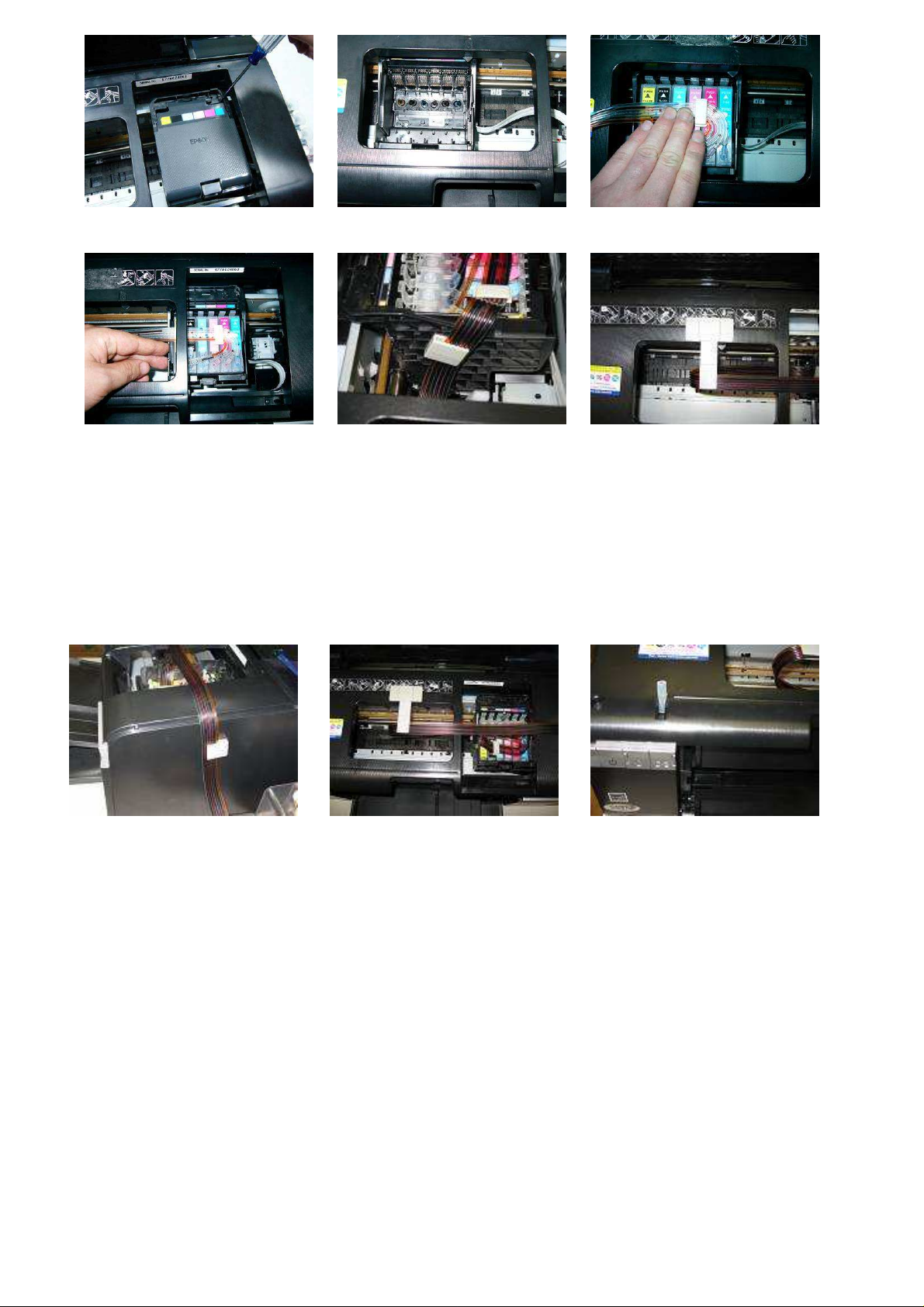
Fig.3-1 Fig.3-2 Fig.3-3
Fig.3-4 Fig.3-5 Fig.3-6
4. Tube Adjustment and Positioning
a. Insert the tubing into one of the square shaped adhesive pads and then place the pad on the left side of the cartridge
compartment as shown (fig.3-5).
b. Place the T shape adhesive pad as shown (Fig 3-6).
c. Place the second square shaped adhesive on the outside of the printer as shown (fig.4-1).
d. Adjust tubing between cartridge compartment and tube guide to correct length; allowing enough room for the
cartridge to move back and forth freely ,making sure the tubes are not twisted and are straight (Fig.4-2).
e. Insert the plastic tube into the sensor slot for the cover on the printer as shown (fig. 4-3).
Fig 4-1 Fig 4-2 Fig 4-3
d. Turn on the printer and make sure the system moves smoothly.
5. Refilling Ink
When the ink levels reach the indicator margin (sticker on the ink tank with red line Fig 5-1) the ink tank system
has reached its low level line and needs to be refilled.
Follow these steps:
1. Gently remove the air breather plugs in order to have more filling room.
2. Remove plugs off of the filling hole(Fig 5-2) and refill the proper color of ink into the corresponding ink tank
(Fig 5-3),(use towel to wipe off any spillage).
3. Make sure you use the specially designed inks Low Foam Ink for the CI System as they are specifically designed
for optimal results.
NOTE: When removing the CIS, remove cartridges and put tape or a napkin over dispensing hole.
Printer and ink tank MUST remain at the same level (not higher and not lower).
2008-8-14 13:38 PM
Page 3

6. Attention:
7. Caution:
Fig 5-1 Fig 5-2 Fig 5-3
1. After installing the CI System ,do not remove the cartridges unless it is necessary .If cartridges are removed,
Immediately place cartridges upside down with ink exit holes facing up to avoid leaking .If cartridges are
removed for more than an hour, please cover ink exit holes with tape.
2. When you are printing do not move the ink tank up or down. Keep it stable and at the same level as the printer.
3. Store at 15-35 degrees Celsius.
4. The ink and cartridge flow have been designed and tested to function as a system. We recommend you use the
specially designed ink Low Foam Ink in the CIS for optimal results.
1. Do not ingest ink and keep out of reach of children
2. Do not leave under sunlight or in extreme weather conditions
3. Do not drop ink tank or handle roughly
To reset the cartridges follow step 8
Fig 8-1
8. When you get the “Replace Cartridge “ message follow these steps.
a. Click on the “How to” button.
b. You will get a screen that tells you to use Epson ink cartridges, click on the “Next” button.
c. The 2nd screen tells you to remove cartridges from the package, click on the “Next” button.
d. The 3rd screen lets you know it’s going to move the printheads to replacement position, click on the “OK” button.
e. The 4th screen tells you to remove cartridges, click on the “Next” button.
f. The 5th screen tells you to install cartridges, when you get this screen the first thing you need to do is push the Reset
button that is on top of the cartridges ( fig. 8-1). Push this button once and then click on the “OK” button.
g. the next screen should show you that the ink is charging, when it is done charging click on the “finish” button.
Fig 8-1
2008-8-14 13:38 PM
Page 4

Thank you for purchasing the Continuous Ink System: We hope you found this manual useful.
Troubleshooting tips
Problem Suggestion
If the ink tank is full of ink computer shows a message
“Replace Cartridge”, That the cartridges are empty.
1
The printer keeps track of how much ink is being used
Please refer to the reset procedure.
Step 8.
and thinks that the cartridge should be empty so you will
have to reset the cartridges chips.
2
Banding or white lines in my print outs.
There is air in the system or cartridges. Try running a couple of
cleaning cycles. If white lines continue use the provided
syringe to suck the air out of the bottom of the trouble cartridge
and you can dump the ink that fills the syringe back into the top
of the CI system. (Make sure to thoroughly rinse the syringe
when completed.)
3
When I have completed a printing job the ink is
siphoning backwards down the tubing.
The shipping plugs need to be removed before installing and
replaced with the air breathers to eliminate any pressure being
built up in the system, along with protecting the ink from
contamination. Also the ink tank should be sitting on the same
level surface as the CI system. If the air breathers are covered
with dried ink, you can rinse the air breather and dry
thoroughly to regain use.
The tubing is getting caught inside the printer resulting
4
in an error message“paper loading error”.
If the tubing is not adjusted correctly, if it’s to short or to long
causing it to slap the inside of the printer, Please adjust.
5
After refilling the tanks the printer won’t print.
If the ink is dumped into the system to quickly then it allows
air to enter the system. Use the provide syringe to extract ink
and air from the bottom of the cartridges. The ink that fills the
syringe can be slowly dumped back into the top of the ink tank.
After installing the CI system the printer isn’t
6
recognizing some of the cartridges.
Remove the cartridges, turn off the printer and reinstall the
cartridges. Then you can continue printing.
If you are still unable to fix the problem call your dealer for support.
2008-8-14 13:38 PM
 Loading...