

Page 1
EPSON PROGRESSION
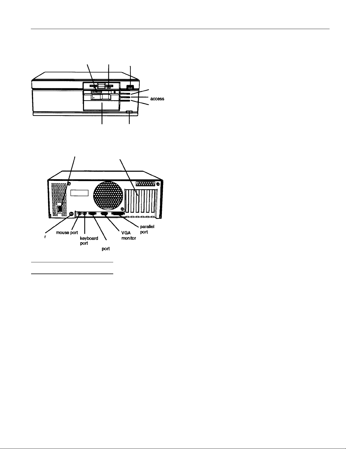
diskette
.
release
button
serial port
power
button
I
RESET
button
option card slots
power light
hard disk
TURBO light
diskette
release
latch
optional drive bay
power inlet
cove
lock
Computer Specifications
CPU and Memory
CPU (on card) 486SX/25 card: Intel 486SX, 25 MHz
microprocessor soldered on CPU card;
additional socket for optional Intel
ODP486SX/25 OverDrive module to
double internal clock speed (50 MHz);
OverDrive module cannot be installed if
487SX/25 microprocessor chip is installed
in shared socket
486DX/33 card: Intel 486DX, 33 MHz
microprocessor socketed on CPU card;
additional socket for optional Intel
ODP486DX/33 OverDrive module to
double internal clock speed (66 MHz)
486DX2/66 card: Intel 486DX2,66 MHz
microprocessor socketed on CPU card;
additional socket for optional (future)
Intel OverDrive module
System speed
Memory
ROM
Video RAM
Shadow RAM
Cache
VirtualCache
Math
coprocessor
Clock/calendar
High, low, and automatic speeds available;
high speed is CPU dependent, low speed
is simulated 8 MHz speed, automatic
speed switches from high to low only for
diskette drive access; speed selection
through SETUP, keyboard command, or
ESPEED program; 0 wait state memory
access at high speed
4MB RAM standard soldered on main
system board; expandable using 1MB,
4MB, 16MB, or 64MB SIMMs to 128MB
(maximum); SIMMs must be 36-bit,
fast-page mode type with 70 ns (or faster)
access speed
128KB system BIOS ROM and SETUP code
located in FLASH memory device on CPU
card; 64KB boot ROM contained in
EPROM on main system board
1MB VRAM on main system board;
additional 1MB VRAM on optional
enhanced video daughterboard (2MB
VRAM maximum)
Automatic shadowing of system and VGA
BIOS ROM into RAM; shadow RAM
address control selectable through SETUP
8KB of internal cache (built into the
microprocessor); cache testing and address
control selectable through SETUP
Epson proprietary VirtualCache feature
automatically creates a “virtual cache”
buffer the size of maximum system
memory
486SX/25 card: socket for optional Intel
487SX, 25 MHz microprocessor chip with
built-in math coprocessor; microprocessor
chip cannot be installed if OverDrive
module is installed in shared socket
486DX/33 card: math coprocessor built
into the 486DX microprocessor; additional
socket for optional Weitek 4167, 33 MHz
math coprocessor
486DX2/66 card: math coprocessor built
into the 486DX2 microprocessor;
additional socket for optional Weitek 4167,
33 MHz math coprocessor
Real-time clock, calendar, and CMOS
RAM socketed on main system board;
separate battery backup
10/19/92
Epson Progression-l
Page 2
EPSON PROGRESSION
OverDrive
Module
Controllers
Video
Diskette
Hard disk
Interfaces
Monitor
Parallel
Serial
Keyboard
Mouse
Option slots
486SX/25 card: socket for optional Intel
ODP486SX/25 OverDrive module to
double internal clock speed (50 MHz);
module cannot be installed if 487SX/25
microprocessor chip is installed in shared
socket
486DX/33 card: socket for optional Intel
ODP486DX/33 OverDrive module to
double internal clock speed (66 MHz)
486DX2/66 card: socket for optional
(future) Intel OverDrive module
Chips and Technologies 64200 Wingine
VGA controller on main system board;
daughterboard provides resolutions up to
1024 x 768; optional enhanced video
daughterboard provides resolutions up to
1280 x 1024 and 24-bit true color display
Controller on main system board supports
up to two diskette drives and one tape
drive
Interface on main system board supports
up to two IDE hard disk drives with
built-in controllers
VGA interface built into video daughterboard for analog or multifrequency VGA
monitor; 15-pin, D-shell connector
One standard 8-bit parallel, mono- or bidirectional interface built into main system
board; port assignment and I/O address
selectable through SETUP; 25-pin, D-shell
connector
One RS-232C, programmable,
asynchronous interface built into main
system
board; port assignment and I/O
address selectable through SETUP; 9-pin,
D-shell connector
PS/2 compatible keyboard interface built
into main system board; keyboard speed,
delay, and num lock settings selectable
through SETUP; 6-pin, mini DIN connector
PS/2 compatible mouse interface built into
main system board; 6-pin, mini DIN
connector
Six standard 16-bit I/O expansion slots;
ISA compatible; 8 MHz bus speed
Speaker
Internal; operation controllable through
SETUP and volume selectable by software
Alternate VGA
IBM compatible VGA pass-through
interface built into main system board;
26-pin connector
Mass Storage
Up to five drives maximum; one
full-height or two half-height internal
drives; one third-height and two
half-height, or one third-height and one
full-height, externally-accessible drives
Keyboard
Detachable; two-position height; 101 or 102
sculpted keys; country-dependent main
typewriter keyboard; numeric/cursor
control keypad; four-key cursor control
keypad; 12 function keys
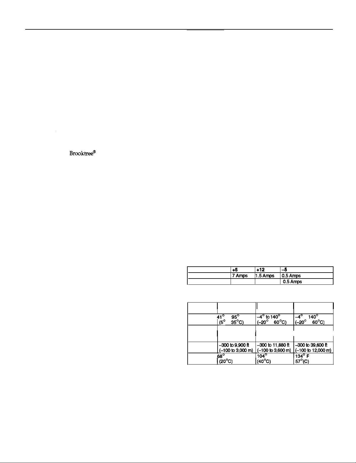
Power Supply
Type
Input ranges
Maximum
outputs
Frequency
(Europe only)
Cables
200 Watt, fan-cooled, automatic input
voltage sensing, thermally protected
98 to 132 VAC and 195 to 264 VAC
+5 VDC at 22 Amps, +12 VDC at 6.8
Amps, -5 VDC at
0.5 Amps
47 to 63 Hz
Three to main system board; five to mass
storage devices
Option Slot Power Limits
Maximum current
For each slot
For all six slots
Volts
16Amps 3Amps 0.5Amps
Environmental Requirements
Condition
Temperature
Humidity
(noncondensing)
Altitude
Maximum
wet bulb
Operating range
to
F
to
20% to 80%
F
Nonoperating
range
10% to 90%
0.5 Amps,
140’ F
to
F
-12
VDC
at
Volts and -12 Volts
Storage range
to 140’ F
to
10% to 95%
I I
Epson Progression-2
10/19/92
Page 3
EPSON PROGRESSION
Physical Characteristics
Width 17 inches (432 mm)
Depth
16 inches (406 mm)
Height 6 inches (153 mm)
Weight Single diskette drive model (without
keyboard): 26 lb (11.8 kg)
Extended VGA Modes
Slxe Type Color DotCLK MemCLK type
60
61
62
64
65
132 x 25
132 x 50
132x43
80x43
80x50
These modes require 512KB of video memory (mapped into VGA
Text
(8x16)
Text
(8x8)
Text
(8 x 8)
Text
(8 x 8)
Text
16
16
16
16
16
40 MHz
40 MHz
40 MHz
25 MHz
25 MHz
Mode
NI
NI
NI
NI
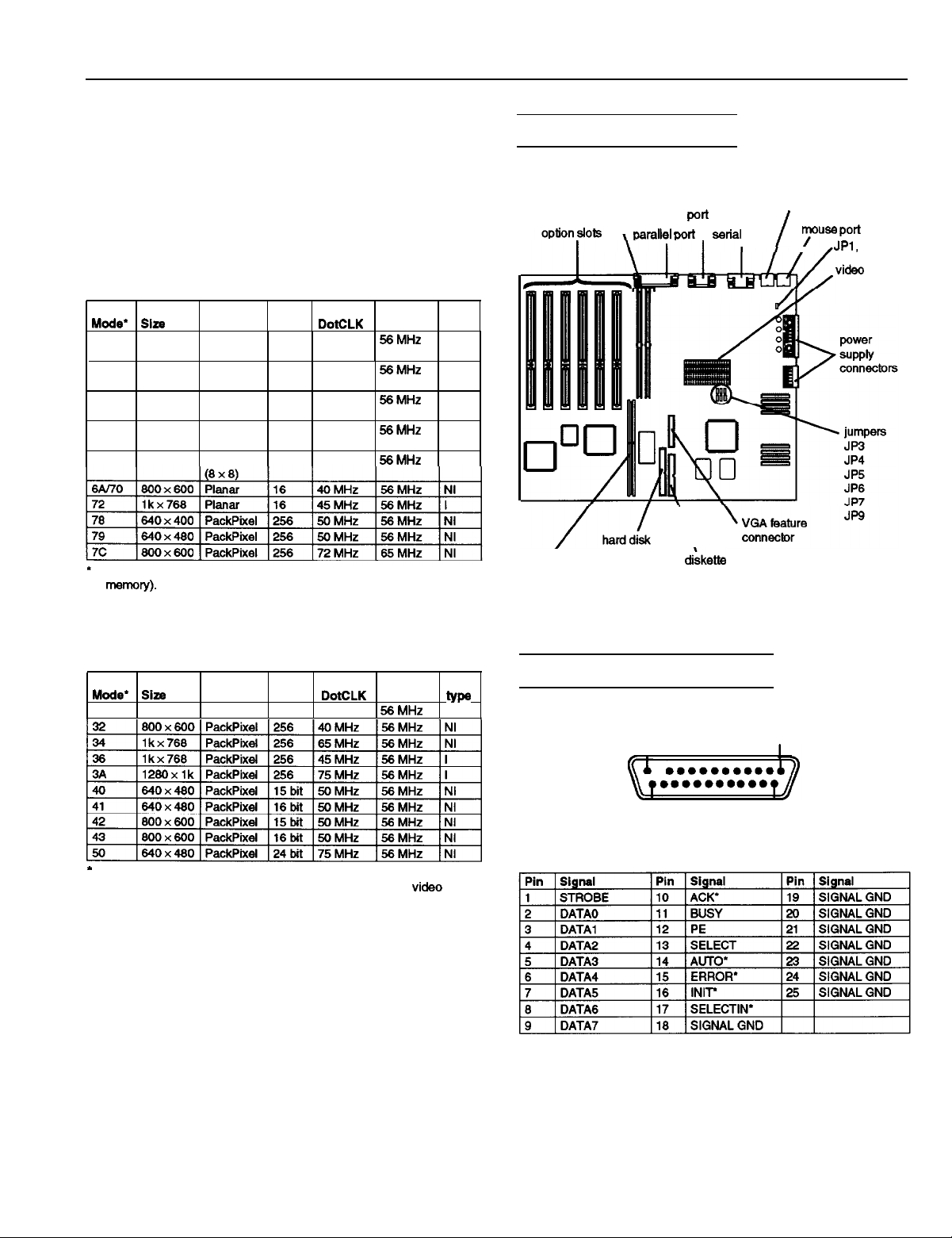
Main System Board Map
VGA
monitor
I
,
keyboard port
port
.
SIMM
sockets
\
\
CPU c&d
connector
drive
connector
drive
connector
I
JP2
daughterboard
connectors
NI = Non-interlaced
I = Interlaced
Wingine Modes
30
NI = Non-interlaced
I = Interlaced
640 x480 Pa&Pixel 256
These modes require 1 MB of video memory (mapped into extended
memory), except modes 3A and 50, which require 2MB of
memory.
Type
Color DotCLK MemCLK
25 MHz
Mode
Connector Pin Assignments
Parallel Port Connector (CN4)
Pin 13
I
l
I
Pin 25
Parallel Port Connector Pin Assignments
l
Active Low Logic
Pin 1
I
Pin 14
10/19/92
Epson Progression-3
Page 4

EPSON PROGRESSION
Serial Port Connector (CN3)
Serial Port
Pin Signal
1
2
3
4
Connector
Data Carder Detect
Receive Data
Transmit Data
Data Terminal Ready
Not used
Pin Assignments
Pin Signal
6
7
6
9
Data Set
Request To Send
Clear To Send
Ring
Keyboard and Mouse Connector (CN2 and CN1)
Pin 6
Pin 2
Although the keyboard and mouse connectors are physically
identical, they cannot be used interchangeably.
Keyboard Connector Pin Assignments
Pin Signal
1
Keyboard
2
3
Ground 6
Data
Pin 5
Pin 1
Pin
Signal
4 +5 VDC
5 Keyboard Clock
VGA Daughterboard Connectors
(CN23, CN24, CN25, CN26)
There are four VGA daughterboard connectors. The
connectors (36-pin headers) provide the video interface
between the board and the video controller. They are
physically identical, but the pinouts for each are different.
Pin 36
Pin 18
VGA Daughterboard Connector Pin Assignments
Pin 19
Pin 1
Mouse Connector Pin Assignments
Pin Signal
1
Mouse Data
2
3
Ground
Pin
Signal
4
5 Mousa Clock
6 Reserved
VGA Port Connector (CN1)
The VGA port connector (CN1) on either the standard or
enhanced daughterboard is a 15pin, D-shell, female
receptacle, accessible from the rear of the computer.
VGA Port Connector Pin Assignments
Pin
Signal
1 IRed
2
Green
3
Blue
4
Green
5 Reserved
Pin
Signal
Ground
7 Ground
Ground
9
NC
10
Ground
Pin
Signal
12
13
Horizontal Sync
14
Vertical Sync
15
NC
Epson Progression-4
10/19/92
Page 5

EPSON PROGRESSION
DMA Channels
Hardware Interrupts
CTRL1
CTRL2
IRQl5
Function
Timer Output 0
Keyboard
I/O Port Addresses
Address
MO-021
060
06F
070
07F
080
09F
OAO - OBF
OCO - ODF
OF1
OF8 - OFF
170
178
1
Assigned device
DMA controller 1
Interrupt controller 1
Timer/counter
Keyboard controller (8042)
RTC.
DMA page registers, MFG port
interrupt controller 2 (8259A compatible)
DMA controller 2 (8237A-5 compatible)
Clear math coprocessor busy
Reset math coprocessor
Math ca~rocessor
Hard disk controller secondary
Configuration registers
Configuration register unlock port 1
mask resister
I/O Port
3F0
*These I/O address ports are configuration registers.
Addresses (continued)
3FF
Floppy disk drive controller primary
Jumper Settings
See the Main System Board Map on page 3 for the location of
the jumpers on the main system board.
Main System Board
Jumper
number
JP3
JP4
JP5
JP6
JP7
JP9
Factory setting
JP1 and JP2 must be set together.
CPU Card Jumpers
Three CPU cards are available for the Progression: 486SX/25,
486DX/33, and 486DX2/66. The jumper on the 486SX/25
card should always be set to position B. The 486DX2/66 card
has no jumpers. Set the jumpers on the 486DX/33 card
according to the table below.
486DX/33 CPU Card Jumpers
CPU card configuration
Card only; no OverDrive module
ODP486DX/33 module installed
Jumper Settings
Jumper
setting
A’
B
A’
B
A’
B
A
A’
B
A
A’
B
Function
Diskless mode disabled
Diskless mode enabled
Color monitor is installed
mode disabled
Diskless mode enabled
Enables the built-in mouse port
use an external mouse port on an option
Enables an external mouse port on an
option card
disables an external mouse port
Monochrome monitor is installed
Diiies the password function
Enables the password function
Enables the built-in VGA display adapter
Disables the built-in VGA display adapter so
you can use a display adapter on an option
Jumper setting
W1 W2 W3
A
A
A A
A
B
I
10/19/92
Epson Progression-5
Page 6

EPSON PROGRESSION
OverDrive Modules
If you have the 486SX/25 or 486DX/33 CPU card, you can
install an Intel OverDrive module on the card to effectively
double the internal clock speed of the computer’s
microprocessor. Although there is an OverDrive socket on
the 486DX2/66 card, there is no OverDrive module available
for it at this time.
Available OverDrive Modules
CPU card
If you install this module, you cannot also install a 4875X/25
microprocessor chip because both options require the same socket
SIMM Installation
There are two SIMM sockets on the main system board, next
to the option slots. You can install 36-bit, fast-page mode
SIMMs that operate at an access speed of 70ns or faster, with
a capacity of lMB, 4MB, 16MB, or 64MB.
The following table shows the possible SIMM configurations;
do not install memory in any other configuration. Make sure
that both SIMMs operate at the same speed. There is 4MB of
memory soldered onto the main system board.
SIMM Configurations
Hard Disk Drive Types
The following table lists the types of hard disk drives you can
use in the computer. Check this table and the documentation
supplied with your hard disk to find the correct number for
the type of hard disk drive(s) installed in your computer. You
need to enter this number when you set the hard disk drive
configuration in the SETUP program.
Hard Disk Drive Types
12
855
13
306
14
733
15
1617612
Heads
7
8 ,-I
7
4
5
II I I I I
Landing
1733
0
663
977
17 20
17
40
Standard soldered memory
Check with your dealer to see if this SIMM is available
With this memory configuration, the 4MB of soldered memory is disabled.
23 306
24
903
25
776
44 828
45
1024
46
615
l
Actual size when formatted may be slightly different than the size listed
4 0
4
"One
8
"One 775 33 100
10
5
512 1023
8
336 17 10
902 46
34 137
17
17
81
MK-156F
42
40
on the drive label.
Hard disk drive supported in translate mode
Epson drives
Epson Progression-6
1O/19/92
Page 7

EPSON PROGRESSION
Installation/Support Tips
Power
This computer has an automatic input voltage sensing power
supply (between 115V, for USA and Canadian use, and 230V,
for use in other countries). There is no manual switch.
Mouse and Keyboard
When connecting the mouse and keyboard, be careful to
plug them into the proper ports. Although they are
physically identical, they are not interchangeable, and
damage may occur to the ports or the main board.
Installing Diskette Drives
When installing a third-party diskette drive as drive B,
you may need to set the drive select jumper to the second
position and attach the pass-through connector on the
floppy drive controller cable to the drive, not to the end
connector.
If the drive does not function normally, make sure that the
drive type has been correctly selected in SETUP. Also
check that any necessary drivers have been installed
correctly.
Installing Hard Disk Drives
It is recommended that a 16-bit, AT-type hard disk
controller be used if you are installing a drive that cannot
use the embedded IDE interface. Installing a 16-bit
interface will override the embedded IDE port and disable
it, freeing the standard base I/O address and IRQ(s).
SETUP
When using a software package that uses a key disk as its
copy-protection method, try loading it at high speed. If
this does not work, enable Auto Speed in SETUP.
Power-on Password
Make sure that you do not forget the Power-on password
you set up. If you do, it will be necessary to disable it by
moving jumper JP6 on the main circuit board to position A.
Information Reference List
Engineering Change Notices
None.
Technical Information Bulletins
None.
Product Support Bulletins
None.
Related Documentation
TM-PROGRESS
PL-PROGRESS
SPKPROGRESS
Y74599100200
Y74599100100
Y74599100300
Epson Progression Service Manual
Epson Progression Parts Price List
Epson Progression Self Paced Kit
Epson Progression Setup Guide
Epson Progression User’s Guide
Epson Progression VGA Utilities Guide
When installing a hard disk drive, be sure to consult the
drive type table for the drive type parameters (geometry)
which fit the drive you are installing. You can also select a
type with parameters having lesser values, as long as they
do not exceed the maximum capacity (in MB) of your
drive. If there is no match for your drive, enter the exect
parameters using the User Defined option.
Software Problems
When installing a copy-protected software package, first
try the installation at high speed. If this does not work
properly, try switching to low speed for theinstallation. If
you are still unable to load the program at high speed, try
loading at low speed and then switching to high speed.
Processor speed varies depending on the CPU card
installed. For the 486SX/25, high speed is 25 MHz; for the
486DX/33, high speed is 33 MHz; and for the 486DX2/66
card, high speed is 66 MHz. All systems simulate 8 MHz
at low speed.
10/19/92
Epson Progression-7
Page 8

EPSON PROGRESSION
Epson Progression-8
10/19/92
 Loading...