

Page 1

EPSON
User’s Guide
EPA POLLUTION PREVENTER
Printed on recycled paper with 10% post-consumer content
89
Page 2

IMPORTANT NOTlCE
DISCLAIMER OF WARRANTY
Epson America makes no representations or warranties, either express or implied, by or
with respect to anything in this manual, and shall not be liable for any implied warranties
ofmerchantability and fitness for a particular purpose or for any indirect, special, or
consequential damages. Some states do not allow the exclusion of incidental or
consequential damages, so this exclusion may not apply to you.
COPYRlGHT NOTlCE
All rights reserved. No part of this publication may be reproduced, stored in a retrieval
system, or transmitted, in any form or by any means, electronic, mechanical,
photocopying, recording, or otherwise, without the prior written permission of Epson
America, Inc. No patent liability is assumed with respect to the use of information
contained herein. Nor is any liability assumed for damages resulting from the use of the
information contained herein. Further, this publication and features described herein are
subject to change without notice.
TRADEMARKS
EPSON is a registered trademark of Seiko Epson Corporation
EPSON Connection and EPSON Direct are service marks of Epson America, Inc.
General Notice: Other product names used herein are for identification purposes only and
may be trademarks of their respective companies.
The Energy Star emblem does not represent EPA endorsement of any product or service.
Copyright 0 1994 by Epson America, Inc.
Torrance, California, USA 8/94
ii
Page 3

Important Safety Instructions
Read all of these instructions and save them for later reference. Follow
all warnings and instructions marked on the computer.
Unplug the computer before cleaning. Clean with a damp cloth only.
Do not spill liquid on the computer.
Do not place the computer on an unstable surface or near a radiator
or heat register.
Do not block or cover the openings in the computer’s cabinet. Do not
insert objects through the slots.
Use only the type of power source indicated on the computer’s label.
Connect all equipment to properly grounded power outlets. Avoid
using outlets on the same circuit as photocopiers or air control
systems that regularly switch on and off.
Do not let the computer’s power cord become damaged or frayed.
If you use an extension cord with the computer, make sure the total
ampere rating of the devices plugged into the extension cord does
not exceed the cord’s ampere rating. Also, make sure the total of all
devices plugged into the wall outlet does not exceed 15 amperes.
Except as specifically explained in this User's Guide, do not attempt
to service the computer yourself. Adjust only those controls that are
covered by the operating instructions.
Unplug the computer and refer servicing to qualified service
personnel under the following conditions:
If the power cord or plug is damaged; if liquid has entered the
computer; if the computer has been dropped or the cabinet damaged;
if the computer does not operate normally or exhibits a distinct
change in performance.
.
If you plan to use the computer in Germany, observe the following:
To provide adequate short-circuit protection and over-current
protection for this computer, the building installation must be
protected by a 16 Amp circuit breaker.
Beim Anschlul3 des Computers an die Netzversorgung
sichergestellt werden,
16 A
Uberstromschutzschalter
dab
die
Gebaudeinstallation
abgesichert ist.
muh
mit einem
iii
Page 4
Importantes instructions de
s&wit6
Lire attentivement
consulter en
cas de
les
instructions suivantes et
les
conserver pour
besoin. Observer soigneusement tous
les
avertissements et directives marques sur l’ordinateur.
l
Debrancher l’ordinateur avant de le nettoyer. N’utiliser qu’un chiffon
humide.
l
Ne pas placer l’ordinateur sur une surface instable ni pres dune
Veiller a ne
pas renverser de liquides sur l’appareil.
source de chaleur.
l
Ne pas bloquer ni couvrir
introduire
l
Utiliser seulement le type de source d’alimentation
d’objets
dans
les
orifices d’aeration de l’appareil. Ne pas
les
ouvertures.
Clectrique
sur l’etiquette.
l
Tout l’equipement doit Ctre branche sur des prises de courant avec
contact de terre. Ne jamais utiliser une prise sur le meme circuit
qu’un appareil
a
photocopies ou un systeme de controle de
ventilation avec commutation marche-arret automatique.
l S’assurer
que le cordon d’alimentation de l’ordinateur n’est pas
abime ni effiloche.
l
Dans le
s’assurer que l’intensite en amperes requise pour tous
branches sur ce cordon
S’assurer
cas ou on
utilise un cordon de rallonge avec l’ordinateur,
ne
aussi que cette intenste
soit pas superieure
ne
depasse jamais
les
a la
capacite du cordon.
la
somme de 15
appareils
amperes pour l’ensemble des appareils.
les
indique
l
Sauf dans
ne
pas essayer d’entretenir
N’ajuster que
l
Debrancher l’ordinateur et contacter un technicien qualifie dans
les cas
les
specifiques expliques dans ce manuel de l’usager,
ou de
reparer l’ordinateur soi-meme.
commandes d&rites dans
les
directives.
circonstances suivantes:
Si le cordon ou
l’interieur de l’appareil; si on
est endommage;
la
prise sont abimes; si un liquide
a
laisse tomber l’appareil ou
si
l’ordinateur
ne
fonctionne pas normalement ou
a
pen&C
fonctionne dune man&e tres differente de l’ordinaire.
l
Pour utiliser l’ordinateur en Allemagne,
il
est necessaire que le
batiment soit muni d’un disjoncteur de 16 amperes pour proteger
l’ordinateur contre
les
courts-circuits et le survoltage.
iv
a
si le
les
bonier
Page 5

lntroduction
Your EPSON® computer provides powerful system
performance and offers a wide range of enhancement options
System features include:
0
Choice of microprocessor: Intel® or Cyrix® 486SX/ 25
or /33; DX/ 33, /40, or /50; DX2/ 50 or /66; SX2/50;
DX4/ 75 or / 100, or PentiumTMOverDrive
0
Energy Star compliant, low-power standby mode for the
hard disk drive and video display
0
4MB or 8MB of internal memory, expandable to 64MB
0
System and video BIOS shadow RAM
0
8KB of internal cache integrated into the microprocessor
and support for up to 256KB of optional external cache
memory on the main system board
0
Integrated high-speed, local bus SVGA video interface
0
512KB (expandable to 1MB) or 1MB of on-board video
memory
TM
0
Video resolutions up to 1280 x 1024 in 16 colors (with 1MB
of VRAM)
0
True Color™ support in the 640 x 480 resolution with 1MB
of VRAM
0
Two built-in serial ports and one built-in bi-directional
parallel port
0
One built-in PS/2™ compatible keyboard port and one
built-in PS/ 2 compatible mouse port
Introduction 1
Page 6

Five 16-bit, ISA-compatible option slots: three full-length,
and two half-length
Space for up to four mass storage devices (three externally
accessible and one internal)
On-board support for up to two IDE hard disk drives and
two diskette drives (or one diskette drive and one tape
drive)
Math coprocessor integrated into the DX, DX2, and
Pentium microprocessors
Real-time clock and calendar on main system board with
built-in rechargeable battery backup.
Using the built-in interfaces, you can connect most of your
peripheral devices directly to the computer so you do not have
to install option cards. You can use the option slots to enhance
your system with extra functions such as a modem card, a
network controller card, or additional interface ports.
The shadow RAM feature allows your system to speed up
processing by moving the system and video BIOS into the
RAM area of memory.
Video
The local bus SVGA video interface provides data transfer at
the full speed of the processor, rather than at the standard
8.33 MHz ISA bus speed.
With 512KB of video RAM, the SVGA controller supports
standard resolutions up to 640 x 480 in 16 colors and extended
resolutions up to 640 x 480 in 256 colors or 1024 x 768 in 16
colors (interlaced and non-interlaced). With 1MB of VRAM, it
supports extended resolutions up to 1280 x 1024 in 16 colors.
2 Introduction
Page 7

Energy Savings
In standard configurations, this computer complies with the
United States Environmental Protection Agency’s Energy Star
Program, which promotes the manufacture of energy-efficient
printers, computers, and monitors. Your computer’s
“Green PC” feature places the hard disk drive in a low-power
standby mode when the mouse and keyboard have been
inactive for a specified period of time. It also stops sending
video signals to your monitor.
Note
If you have an Energy Star compliant monitor, it also goes
into a low-power standby mode because it isn’t receiving
video signals from your computer. (Screens on
non-compliant monitors go blank, but do not enter a
low-power standby mode.)
VGA Drivers
Your computer comes with VGA drivers and utilities for use
with the integrated video interface. With these drivers, you can
take advantage of the extended VGA features such as higher
resolutions and 132-column text mode when you run popular
applications. If your system was configured for you, these
drivers and utilities may be installed on your hard disk. If you
need to install them yourself, see the instructions in Chapter 1.
To obtain drivers for additional applications, call the EPSON
ConnectionSM or access the Epson America Forum on
CompuServe®.
Introduction 3
Page 8

Optional Equipment
You can easily upgrade your computer by installing additional
memory and a wide variety of options, as described in
Chapters 3 and 4.
Memory By adding 1MB, 2MB, 4MB, 8MB, 16MB, or
32MB SIMMs (single inline memory
modules) to the main system board, you
can expand the computer’s memory up to
64MB.
Video
Memory
CPU
Cache
Drives
You can increase the video memory in
your system to 1MB, which allows you to
use higher resolutions with more colors.
Your system supports a variety of
microprocessors, including 5 Volt, 3.3 Volt,
3.45 Volt, and 3.6 Volt processors; see
Chapter 3 for more information.
You can increase the external cache
memory size to 64KB, 128KB, or 256KB by
installing cache SRAM chips on the main
system board, allowing you to access data
faster and improve overall system
performance.
Your system supports up to four mass
storage devices, including hard disk
drives, diskette drives, a tape drive, a
CD-ROM drive, or an optical drive.
4 Introduction
Page 9

How to Use This Manual
You do not have to read everything in this manual; check the
following chapter summaries.
Chapter 1 provides simple instructions for setting up your
system and for turning it on and off. It also describes running
the SETUP program to define your computer’s configuration.
Chapter 2 covers general operating procedures, resetting the
computer, using the Green PC features, and changing the
processor speed.
Chapter 3 describes how to remove and replace the computer’s
cover, change jumper settings, and install optional equipment
such as option cards and memory modules.
Chapter 4 explains how to install and remove drives
Chapter 5 contains troubleshooting tips.
Appendix A lists the specifications of your computer.
At the end of this manual you’ll find a Glossary, an Index, and
a list of EPSON’s U.S. and international marketing locations.
Introduction 5
Page 10

Where to Get Help
If you purchased your computer in the United States or
Canada, EPSON provides customer support and service
through a network of Authorized EPSON Customer Care
Centers. EPSON also provides support services through the
EPSON Connection. In the United States, dial (800) 922-8911. In
Canada, dial (800) GO-EPSON.
Call the EPSON Connection for the following:
Technical assistance with the installation, configuration,
and operation of EPSON products
Assistance in locating your nearest Authorized EPSON
Reseller or Customer Care Center
Customer Relations
EPSON technical information library fax service
Product literature on current and new products.
You can purchase accessories, manuals, or parts for EPSON
products from EPSON Accessories at (800) 873-7766 (U.S. sales
only). In Canada, call (800) GO-EPSON for sales locations.
When you call for technical assistance, be ready to identify
your system and its configuration, and provide any error
messages to the support staff. See Chapter 5 for more
information.
If you purchased your computer outside the United States or
Canada, contact your EPSON dealer or the marketing location
nearest you for customer support and service. International
marketing locations are listed at the end of this manual.
6 Introduction
Page 11

If you need help with any software application program you
are using, see the documentation that came with that program
for technical support information.
CompuServe On-line Support
If you have a modem, the fastest way to access helpful tips,
specifications, drivers, application notes, tables for DIP switch
or jumper settings, and bulletins for EPSON products is
through the Epson America Forum on CompuServe.
If you are not currently a member of CompuServe, you are
eligible for a free introductory membership as an owner of an
EPSON product. This membership entitles you to:
0
An introductory $15 credit on CompuServe
0
Your own user ID and password
0
A complimentary subscription to CompuServeMagazine,
CompuServe’s monthly publication.
To take advantage of this offer, call (800) 848-8199 in the United
States and Canada and ask for representative #529. In other
countries, call the following U.S. telephone number:
(614) 529-1611 or your local CompuServe access number.
If you are already a CompuServe member, simply type
GO EPSON at the menu prompt to reach the Epson America
Forum.
Introduction 7
Page 12

Contents
Introduction
Video
Energy Savings
VGA Drivers
Optional Equipment
How to Use This Manual
Where to Get Help
Chapter 1
Unpacking Your Computer
Setting the Voltage Selector Switch
Connecting System Components
Connecting the Power Cord
Turning Your System On and Off
Running the SETUP Program
...................................
..............................
...............................
..........................
........................
............................
CompuServe On-line Support
Setting Up Your-System
Starting the SETUP Program
The System Setup Option
The Fixed Disk Setup Option
The Advanced System Setup Option
Setting the Boot Options
The System Security and Anti-Virus Options
Using the Green PC Features
The System Summary Option
Exiting SETUP
Post-SETUP Procedures
...........................
..................
......................
..................
...................
......................
...................
.....................
..................
....................
..................
.....................
..................
..................
.....................
..............
.........
2
3
3
4
5
6
7
1-1
1-2
1-4
1-5
1-5
1-7
1-8
1-9
1-10
1-11
1-13
1-15
1-18
1-19
1-19
1-20
V
Page 13

Chapter 2
Using Your Computer
Working Comfortably
Stopping a Command or Program
Resetting the Computer
Using Energy Wisely
Using Your Green PC Features
Changing the Processor Speed
Chapter 3
Removing the Cover
Replacing the Cover
Installing and removing Options
........................
........................
............
............
Locating the Internal Components
Changing the Jumper Settings
Setting the Jumpers
Installing Memory Modules
Inserting SIMMs
........................
Removing SIMMs
Installing an Option Card
........................
........................
........................
........................
........................
Installing a Card in a Full-length Slot
Installing a Card in a Half-length Slot
Removing an Option Card
Adding Video Memory
Installing External Cache
........................
........................
........................
Installing the External Cache Chips
Upgrading the Microprocessor
Replacing the Processor Chip
Post-installation Procedures
........................
............
............
............
............
........................
........................
........................
........................
........................
........................
2-1
2-2
2-3
2-4
2-4
2-5
3-2
3-4
3-5
3-6
3-8
3-9
3-11
3-12
3-14
3-15
3-16
3-17
3-18
3-20
3-21
3-23
3-24
3-26
Chapter 4
Removing the Drive Mounting Bracket
Installing and Removing Drives
........................
Installing a Hard Disk Drive in the Mounting Bracket
Removing the Mounting Frames
Installing the Hard Disk Drive
Replacing the Bracket in the Computer
........................
Connecting the Drive Cables
Reconnecting the Cables to the Diskette Drive
vi
........................
........................
........................
........................
........................
4-2
4-3
4-5
4-6
4-8
4-9
4-13
Page 14

Removing a Hard Disk Drive From the Mounting Bracket
Installing a Drive in an External Drive Bay
Attaching Mounting Frames to the Drive
Installing the Drive
........................
Connecting the Drive and Power Cables
Removing a Drive from an External Bay
Post-installation Procedures
........................
........................
........................
........................
........................
........................
4-14
4-15
4-16
4-17
4-19
4-21
4-22
Chapter 5
Identifying Your System
The Computer Will Not Start
Troubleshooting
........................
........................
The Computer Does Not Respond
Keyboard Problems
Mouse Problems
Monitor Problems
Diskette Problems
Diskette Drive Problems
Hard Disk Drive Problems
Password Problems
Software Problems
Printer Problems
Option Card Problems
Memory Module Problems
Controller Problems
External Cache Problems
Appendix A Specifications
CPU and Memory
Controllers
Interfaces
................................
.................................
Mass Storage
Keyboard
Mouse
.................................
...................................
SETUP Program
Physical Characteristics
Power Supply
Option Slot Power Limits
........................
........................
........................
........................
........................
........................
........................
........................
........................
........................
........................
........................
........................
............................
...............................
.............................
.........................
...............................
........................
........................
5-1
5-3
5-4
5-5
5-5
5-6
5-7
5-8
5-8
5-10
5-11
5-12
5-12
5-13
5-14
5-14
A-1
A-3
A-3
A-4
A-5
A-5
A-5
A-5
A-6
A-6
vii
Page 15

Environmental Requirements
Video Resolutions and Colors
Hard Disk Drive Types
Drive Option Information
Options Available from EPSON
Tested Operating Environments
DMA Assignments
Hardware Interrupts
System Memory Map
System I/O Address Map
........................
Connector Pin Assignments
Glossary
Index
........................
........................
........................
........................
........................
........................
........................
........................
........................
........................
A-6
A-7
A-8
A-10
A-11
A-12
A-12
A-13
A-14
A-14
A-16
viii
Page 16
Chapter 1
Setting Up Your System
This chapter briefly describes how to set up your computer. It
includes the following information:
0
Unpacking your computer
0
Setting the voltage selector switch
0
Connecting system components
0
Turning the computer on and off
0
Running the SETUP program
0
Post-SETUP procedures.
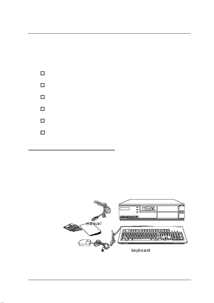
Unpacking Your Computer
When you unpack your system, make sure you have the items
shown below.
diskettes
mouse
power
cord
computer
Setting Up Your System
1-1
Page 17

If you purchased any optional equipment that goes inside the
computer-such as option cards, memory modules, or
drives-you should install these devices before you connect
your computer. See Chapters 3 and 4 for instructions.
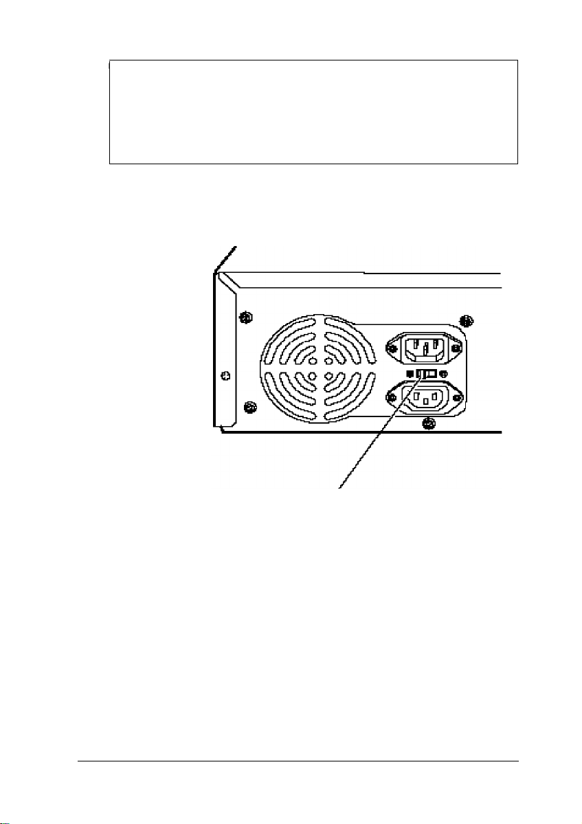
Setting the Voltage Selector Switch
Your system is powered by a 200 Watt power supply. The
power supply voltage is controlled by a voltage selector switch
on the computer’s back panel. You can set this switch to
110 VAC or 220 VAC.
EPSON ships the computer with the voltage selector switch set
to 110 VAC. This setting is appropriate for line source voltages
between 100 and 120 VAC, and is generally the appropriate
setting to select if you plan to use your computer in North
America, South America, or Japan.
If you plan to operate the computer in the United Kingdom,
Europe, or some South American countries, you will probably
need to reset the voltage selector switch to 220 VAC. Doing so
allows your computer to handle line source voltages between
200 and 240 VAC, which are standard in Europe.
1-2 Setting Up your System
Page 18
Caution
Before you turn on the power to your system, make sure the
voltage selector is set to the appropriate setting for the
electrical power source in your location or you will seriously
damage your system.
To change the voltage selector switch setting, slide the switch
to the right to select 220 VAC or to the left to select 110 VAC.
voltage selector switch’
Setting Up your System 1-3
Page 19
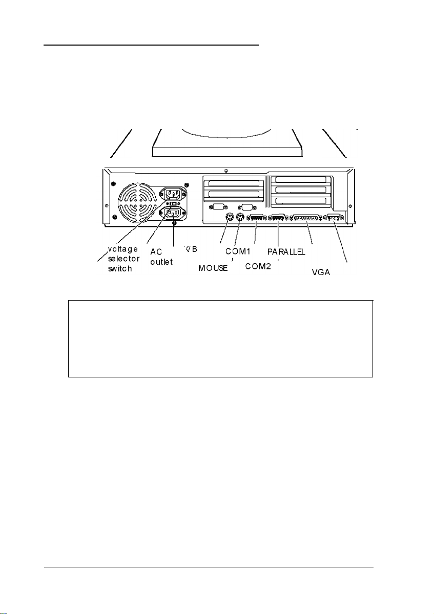
Connecting System Components
Use the following illustration to locate the ports on the back of
your system as you connect the keyboard, monitor, printer, and
other devices.
/
c
power
inlet
Caution
Although the connectors and ports for the mouse and
keyboard are physically identical, they cannot be used
interchangeably. Be sure to plug the mouse connector into
the MOUSE port, or you may damage your system.
\-
Your computer also includes two removable panels above the
mouse and keyboard ports providing access to a game port on
the main system board and to one on an option card, if you
installed one. You can enable the main system board game port
via a jumper; see Chapter 3.
1-4 Setting Up your System
Page 20

Connecting the Power Cord
Follow these steps to connect the power cord:
1.
Plug the power cord into the power inlet on the back panel
of the computer.
WARNING
To avoid an electric shock, be sure to plug the cord into
the computer before plugging it into the wall outlet.
2.
Plug the other end of the power cord into an appropriate
grounded electrical outlet.
After you connect the components of your system, you are
ready to turn on the power.
Turning Your System On and Off
Before you turn on your system, be sure to read the Important
Safety Instructions at the beginning of this manual.
Caution
If there is a protective card in a diskette drive, remove it now
or you may damage your drive.
First turn on the monitor, printer, and any other external
devices connected to the computer.
Setting Up your System 1-5
Page 21
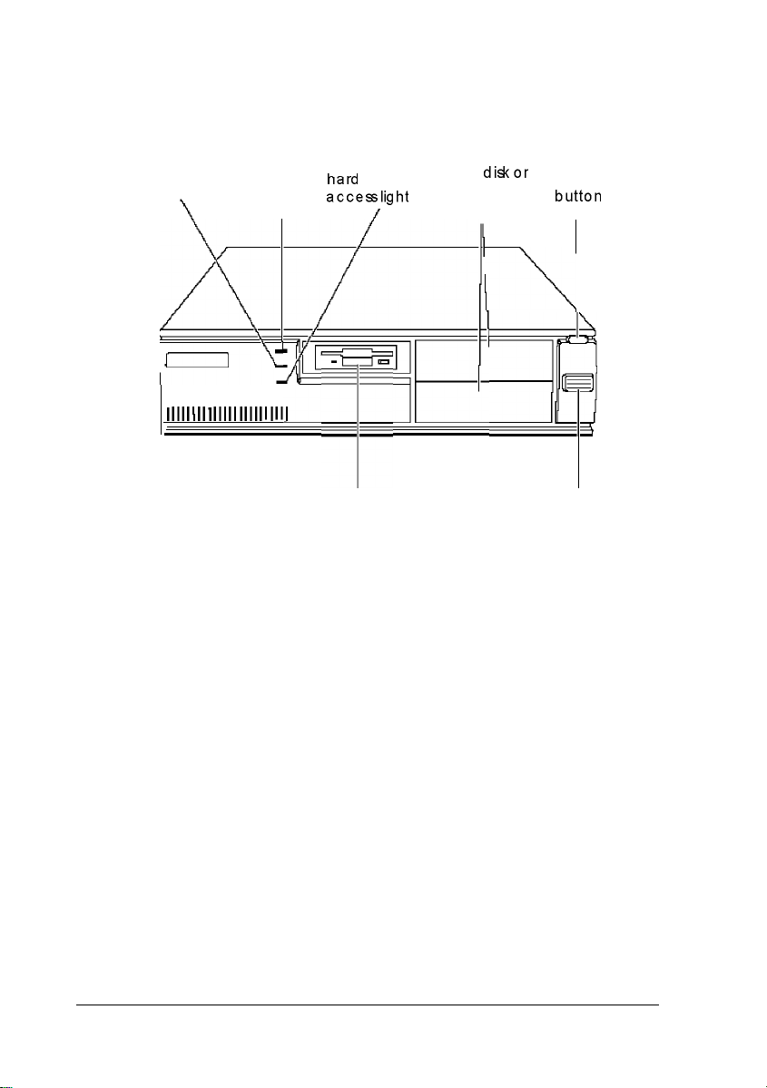
Then turn on the computer by pressing the power button
located on the right side of the front panel, as shown below.
hard
speed light
“-rd
powerlight --
,,a
dticesslight
I
disk
I
diskor
diskette drive
bays
reset
button
I
1
--
&.I.~
IIIIIIIIIIIIIIIIIIIIIIII
The power indicator lights up. After a few seconds, the
computer performs its power-on diagnostics. This is a series of
everything is working correctly.
If necessary, use the controls on your monitor to adjust the
on the screen.
Whenever you turn off your system, be sure to save your data
the hard disk drive light and the diskette drive light(s) to make
sure they are not on. Press the power button to turn off the
peripheral devices.
-qFY+
T
diskette drive
q
Now follow the instructions below to configure your system
1-6
Page 22

Running the SETUP Program
Be sure to run SETUP the first time you use your computer, so
you can verify or update the configuration information. You
also may need to run SETUP again later if you change your
configuration.
SETUP lets you verify or change the following:
0
System settings such as date, time, diskette drive type(s),
and video display type
0
Automatic or manual selection of hard disk drive(s)
0
Automatic or manual selection of advanced hardware
features for optimizing system performance
0
System booting options
0
Password security and anti-virus features
0
Green PC options, such as the time intervals before the
system and the hard disk drive go into low-power standby
mode.
SETUP also allows you to see summary information about your
system.
The SETUP program and the factory default settings are stored
in the computer’s ROM BIOS (read-only memory, basic
input/ output system). The configuration information you enter
is stored in an area of memory called CMOS RAM. This
memory is backed up by a battery, so it is not erased when you
turn off or reset the computer.
Setting Up your System 1-7
Page 23

Starting the SETUP Program
When you start your computer, it performs some power-on
diagnostics. During these diagnostics, you may see the
following message:
Press <F2> to enter SETUP
(In SETUP, you can disable this message, if desired.)
Press F2 to run SETUP. This message is only on the screen for a
few seconds. If you missed it, restart the computer and try
again.
If the system detects an error in your configuration, you hear
two beeps and see an error message followed by this message:
Press <F1> to resume, <F2> to Setup
Press F2 to run SETUP.
SETUP displays the Main Menu. From this menu, you can
select the various options to identify your system’s
configuration and then save your new values to CMOS. If you
change your mind, you can cancel any changes you have made
and restore the default values stored in ROM or load the values
previously stored in CMOS.
The table below lists the keys you can use to perform SETUP
operations.
SETUP function keys
Key
f&t +
Home End
F1 or Alt H
Function
Move the cursor to the next or previous modifiable option
Move the cursor to the top or bottom of the menu
Displays a help screen describing the option currently
selected
1-8 Setting Up your System
Page 24

SETUP function keys (continued)
Key
F5 orF6 or + or
Spacebar
F9
F10
Enter
Esc or Alt X
Function
Selects the previousvalue
Selects the next value
Loads the factory default values for the SETUP options on
the current Screen
Ignoresany changesyou have made on the current
Screen
Selects the current option or value
Returnsto the previousscreen
Whenever you are in SETUP, the bottom of the screen lists the
keys you can press to perform specific functions.
The System Setup Option
From the System Setup screen, you can set the options
described below.
Setting the time and date
The real-time clock in your computer continuously tracks the
date and time-even when the computer is turned off. Once
you set the System Time and System Date options, you
should not need to change them, unless you adjust the time for
daylight savings or a different time zone. (The computer
automatically changes the date for leap years.)
Setting the video display type
The Video Systemoption allows you to define the type of
display adapter you are using. If you connected your monitor
to the computer’s built-in VGA port, select EGA/VGA.
Setting Up your System
1-9
Page 25

If you connected a monitor that doesn’t support VGA to a
video adapter card installed in your system, select either the
CGA 80 X 25 or the Monochrome option. Also make sure
you disabled the on board VGA controller by setting jumpers
J14 and J15 to the Off position. (See Chapter 3 for instructions.)
Checking system memory
When you boot your system, the system BIOS detects the total
memory size automatically. You see the memory configuration
displayed in the System Memory and Extended Memory
fields on this SETUP screen.
You cannot change these values; if they are not what you
expect them to be, check that the SIMM(s) are securely seated
in their sockets. (See Chapter 3 to locate the SIMM sockets.)
Setting the diskette drive type(s)
On your system, diskette drive A is the 3.5-inch high-density
drive installed in your computer. You may also have another
drive of a different size or capacity; this is drive B. Check the
settings for both drives and correct them if necessary.
The Fixed Disk Setup Option
The options on the Fixed Disk Setup screen define the types of
hard disk drives you installed in your system. From this screen,
select Fixed Disk 0 Control or Fixed Disk 1
Control.
Your computer comes with a hard disk auto-sensing feature.
Press Enter when the Autotype Fixed Disk option is
highlighted. The system detects the type of hard disk drive and
fills in the remaining fields on the screen.
1-10 Setting Up your System
Page 26

If you are using an older drive or a preformatted drive, it may
not support the auto-sensing feature. If you press Enter when
the Autotype Fixed Disk option is highlighted and the
drive parameters do not match your drive, check Appendix A
to see if your drive’s parameters are included in the hard disk
drive table. If not, you need to define your own drive type or
reformat the disk. See the next section for instructions on how
to define your own drive type.
Defining your own drive type
If the parameters for your hard disk do not match the
parameters detected by the auto-sensing feature, or if you want
to use your drive with parameters other than the defaults, you
can define your own type. To define your own drive type,
follow these steps:
1.
Move the cursor to Type and select User.
2.
Type the values in each field that are appropriate for your
hard disk drive.
3.
When you exit SETUP, make sure you save your changes.
The Advanced System Setup Option
When you select this option from the Main Menu, you see the
Advanced System Setup screen, which contains the options
described below.
Your system can automatically configure the Advanced
System Setup options for you. To avoid configuration
problems, you should let the system configure these options.
However, if you connected a scanner or a parallel port network
adapter to your parallel port, be sure to select Advanced
Chipset Control so you can change the operation of the
parallel port to PS2 mode (for bidirectional operation). See
page 1-13 for more information.
Setting Up your System 1-11
Page 27

Configuring cache memory
The system can configure your Memory Cache options or you
can manually set them. If you installed external cache, enabling
cache memory improves system performance, especially in
large data retrieval and processing environments.
If you choose to configure the cache memory yourself (rather
than let the system configure it for you), you can define the
write and burst wait states and two non-cacheable areas of
memory. However, it’s a good idea to let the system
automatically configure these features.
Configuring memory shadow
The system can configure the Memory Shadow options or you
can manually set them. You can enable or disable shadowing of
your system and video memory and control the specific blocks
of ROM used for this purpose.
Your computer can access RAM faster than ROM. The options
on this screen allow your system to copy the contents of its
system and/ or video ROM into RAM. When you use
shadowing, your system can perform certain operations faster,
providing a significant increase in performance.
Note
For the best system performance, always set the System
shadow and the Video shadow options to Enabled.
If you enable shadowing for specific blocks, the ROM located in
these blocks is copied to the shadow area.
1-12
Setting Up your System
Page 28

Configuring chipset registers
The system can set your Advanced Chipset Control
options or you can manually change the values in the chipset
registers. Setting these values correctly increases your system
performance; however, setting them incorrectly may cause
your system to malfunction or shut down. Be sure to set the
Auto Configuration option to Enabled to let the system
automatically configure these options to avoid problems.
However, if you connected a scanner or a parallel port network
adapter to your parallel port, you should set Auto
Configuration to Disabled so you can change the
Printer Port Control option to PS2 mode (for
bidirectional operation). The default setting for the parallel port
is AT mode (for unidirectional operation).
Setting the Boot Options
When you select Boot Options from the Main Menu, you see
the Boot Options screen, which contains the options described
below.
Selecting the drive boot sequence
The Disk drive boot sequence option determines the
order in which the computer checks the drives when it looks
for the operating system.
If you select A: then C:, each time you turn on the
computer, it first tries to load the operating system from drive
A. If drive A doesn’t contain an operating system, the
computer loads it from drive C. If you select C :
computer tries to load the operating system from drive C first.
If drive C doesn’t contain an operating system, the computer
tries to load it from drive A. If you select C:
computer tries to load the operating system from drive C only.
Setting Up your System
then A:, the
only, the
1-13
Page 29

Setting the floppy seek option
If you set the Disk drive boot sequence option to
C: only, you can disable the Floppy seek option so the
system does not try to access the diskette drive at startup.
Disabling the Floppy seek option decreases the time needed
to boot the system.
Disabling the SETUP prompt
The Display SETUP prompt during POST option allows
you to disable the message Press <F2> to enter SETUP
that you see during power-on diagnostics. You may want to
disable this prompt to prevent unauthorized users from seeing
the SETUP prompt. Even when the message is disabled,
however, you can still start SETUP by pressing F2 within the
allowed amount of time.
Disabling power-on diagnostic error messages
The Pause on POST errors option allows you to disable
the error message and the message Press <F1> to
resume, <F2> to Setup that you see when the system
identifies a configuration error. If you disable this option, the
system ignores configuration errors it finds during power-on
diagnostics and starts as it normally would. It’s a good idea to
keep this option enabled.
Disabling the system summary screen
By disabling the System summary screen at boot
option, you can disable the system summary screen that you
see when you start the system. If you disable this option, your
system starts up faster. You can see the same screen by
selecting the System Summary option from the Main Menu.
(See page 1-19.)
1-14
Setting Up your System
Page 30

The System Security and Anti-Virus Options
When you select the Security and Anti-Virus option
from the Main Menu, you see the System Security and
Anti-Virus screen, which contains the options described below.
Entering or changing a password
You can define both User and Supervisor password levels for
this system. If the system will be used by more than one
person, you may want to set a Supervisor password for
yourself and a User password for others you don’t want to
have complete access to the system. For instance, you may
want to restrict access to the diskette drives or the computer’s
virus protection features.
If you enable the Password on boot option, you must enter
the Supervisor or User password each time you turn on the
system. If you do not enable this option but you have defined
passwords, you must enter the password each time you start
the SETUP program. If both a Supervisor and User password
are enabled, SETUP displays options for setting the User
password only for users who logged on with a user password.
To specify a User password, you must first specify a Supervisor
password. Follow these steps to enter or change a Supervisor
password:
1.
Select the Set Supervisor Password option and press
Enter.
2.
You see a Set Supervisor Password window. Type the
password you want to use, then press Enter. You can define
a password of up to eight characters.
3.
Type the same password a second time and press Enter.
You see a message that your changes have been saved.
Setting Up your System 1-15
Page 31

4. Press the spacebar. The Supervisor Password IS option
is now set to Enabled.
To set a User password, select the Set User Password
option and follow the steps above.
Deleting passwords
To delete your passwords, follow these steps:
1.
Set the Password on boot option to Disabled.
2.
Delete the User password by pressing Enter for both the
password field and the confirmation field. Don’t type any
characters in these fields.
3.
Then delete the Supervisor password the same way.
Note
You must delete the User password before SETUP will allow
you to access the Supervisor password.
If you have forgotten your password(s), see “Password
Problems” in Chapter 5.
Using the virus protection features
Several options on the Security and Anti-Virus screen allow
you to define system protection features.
The Diskette Access option allows you to restrict access
to your diskette drives based on the password levels you have
defined. This prevents unauthorized users from accessing the
drives and possibly introducing a virus to your system. You
can restrict diskette access only if passwords are enabled and
you have enabled the Password on boot option.
1-16
Setting Up your System
Page 32

If you select Supervisor for this option, you can access the
diskette drives only if you enter the Supervisor password when
you start your system. Someone who starts the system with a
she tries to access the diskette drive. If you select User for
the Diskette Access option, you can access the diskette
Note
To use passwords for diskette drive access, you must enable
the Password on boot option. If you select a password
level for Diskette Access but leave the Password on
boot option disabled, you see an error message whenever
you try to access your diskette drive.
You can also protect your system by selecting Write
protect for the Fixed disk boot sector option.
When this option is enabled, the system displays an error
message when a program tries to write to the boot sector of
your hard disk drive. To use a legitimate program (such as the
MS-DOS@ FORMAT command) you must disable the write
protect option.
Two additional options on this screen allow you to define time
intervals for the system to display a prompt asking whether
you have performed your scheduled virus check or your
scheduled backup for your hard disk drive. You can disable
these prompts or have them display Daily, Weekly, or
Monthly. If you respond that you have not performed these
functions, however, the system still starts normally.
Setting Up your System
1-17
Page 33

Using the Green PC Features
The Green PC options allow you to define how the
energy-saving features of this Energy Star compliant system
will work for you. The options on the Green PC Features screen
allow you to disable the energy-saving feature or set time-out
periods to put the system and hard disk drive in a low-energy
standby mode.
The Inactivity Timer 1 option sets the time-out period
for video signals to your monitor. When the mouse or
keyboard has been inactive for the time period you select here,
your computer stops sending video signals to your monitor. If
your monitor is also Energy Star compliant, it goes into a
low-power standby mode because it isn’t receiving video
signals from your computer. Screens on monitors that aren’t
Energy Star compliant will go blank when your system is in
standby mode.
If you select a time period for the Lockout Timer as well as
the Inactivity Timer 1 option, the system won’t accept
your keyboard input for the specified period of time after your
system has returned to an active mode. This allows time for
your monitor to return to full power also.
The Fixed Disk Timeout option determines the time-out
period for your hard disk drive. The hard disk drive goes into a
low-power standby mode when the mouse and keyboard have
been inactive for the period of time you’ve indicated.
Note
Some hard disk drives do not support a low-power standby
mode. Also, the delay caused by the hard disk drive
returning to active mode may cause errors in some
applications. If you have problems, you may want to disable
the Fixed Disk Timeout option.
1-18 Setting Up your System
Page 34

The System Summary Option
When you select the System Summary option from the Main
Menu, the SETUP program displays a summary of the
configuration settings for your system.
This is the same screen you see during system startup. You can
choose not to have the system display this screen so system
startup is faster. See page 1-14 for information on disabling this
option
Exiting SETUP
When you leave SETUP, you can save your settings, or exit
SETUP without saving your settings. You can also return all
values to the factory defaults.
To leave SETUP, press
Main Menu, you can do the following:
Load ROM
Default Values
Load Values
from CMOS
Save Values to
CMOS
ESC from any SETUP screen. From the
Loads the factory default settings
stored in ROM back into
CMOS.
If you change your system
configuration and then
have problems, you can
load the ROM values to
boot the system and start
over.
Loads the current values stored in
CMOS for all SETUP options. This
ignores any changes you have
made using SETUP.
Saves the configuration changes
you have made to CMOS.
Setting Up your System
1-19
Page 35

Post-SETUP Procedures
After you run SETUP for the first time, you may need to install
the operating system if your computer is not preconfigured.
See your operating system manual for instructions.
Once you have installed your operating system, install any
software you plan to use. See your application program
manuals for instructions.
You may also want to install the optional extended video
drivers for some of your application programs. (If your
computer was configured for you, these drivers are already
installed.) The README files on Drivers Diskettes 1 and 2
provide instructions for installing and using the drivers.
To read the file on your screen, insert Drivers Diskette 1 in
drive A, type the following, and press
A:\README
To print the file to your printer, type the following and press
Enter:
A:\READMEP
Enter:
Use the same commands to read or print the README file on
Drivers Diskette 2.
Note
If you plan to install video drivers for Microsoft® Windows
applications, you must install Windows before you install
the drivers.
1-20
Setting Up your System
TM
Page 36
Chapter 2
Using Your Computer
This chapter briefly describes the following operations:
0
Working comfortably
0
Stopping a command or program
0
Resetting the computer
0
Using energy wisely
0
Using the Green PC features
0
Changing the processor speed
Working Comfortably
This section provides some tips for creating a comfortable work
environment.
0
Use good posture. Keep your elbows, hips, and knees bent
at approximately 90 degree angles and keep your wrists as
close to horizontal as possible.
0
Vary your posture often and take frequent breaks. Stand
up, stretch, and move around.
0
Use a good chair. Make sure your chair supports your
lower back. A chair with padded armrests lets you rest
your arms as you work.
Using your Computer
2-1
Page 37

If you use a copy stand, keep it at the same eye level as
your screen. This reduces eye and neck strain. Also, rest
your eyes occasionally by closing them or focusing on a
fixed spot in the distance.
Be gentle with your keyboard. Too much force creates
tension in your hands. Also, make sure your work surface
has enough room for you to move the mouse or other
pointing device freely.
Use good lighting that isn’t too bright. Try to keep bright
light sources out of your field of vision when you are
looking at the screen.
Place your monitor directly in front of you and sit about an
arm’s length away from it. The top of the screen should be
slightly below your eye level so you look down at the
screen. Position the monitor so that no light is reflected
from the screen.
Stopping a Command or Program
You may sometimes need to stop a command or program while
it is running. If you have entered an MS-DOS or application
program command that you want to stop, try one of the
following:
0
Press Pause
0
Press Ctrl C
0
Press Ctrl Break.
If these methods do not work, you may need to reset the
computer as described below. Do not turn off the computer to
exit a program or stop a command unless you have to, because
the computer erases any data you did not save.
2-2 Using Your Computer
Page 38

Resetting the Computer
Occasionally, you may want to clear the computer’s memory
without turning it off. You can do this by resetting the
computer.
For example, if an error occurs and the computer does not
respond to your keyboard entries, you can reset it to reload
your operating system and try again. However, resetting erases
any data in memory that you have not saved, so reset only if
necessary.
Caution
Do not reset the computer to exit a program. Some programs
classify and store new data when you exit them normally. If
you reset the computer without properly exiting a program,
you may lose data.
Also do not remove a diskette or reset or turn off the
computer while a diskette drive light is on. You could lose
data. Be sure to remove all diskettes before you turn off the
computer.
To reset the computer, press Ctrl Alt Del. The screen displays
nothing for a moment and then the computer reloads your
operating system.
You can also press the RESET button located in the upper right
corner on the front of your computer.
If resetting the computer does not correct the problem, you
probably need to turn it off and on again. Remove any
diskette(s) from the diskette drive(s). Turn off the computer
and wait 20 seconds. If you do not have a hard disk, insert the
system diskette in drive A. Then turn on the computer.
Using your Computer 2-3
Page 39

Using Energy Wisely
By purchasing this low-power, Energy Star compliant
computer, you join a growing number of users concerned about
conserving energy. Here are a few additional tips you can use
to be even more energy-wise:
0
If your printer and monitor aren’t Energy Star compliant,
turn them off when you’re not using them.
0
Use your software’s print preview option (if available)
before you print something. You’ll be able to catch
formatting errors before you commit them to paper.
0
If you have an electronic mail system available to you, send
E-mail rather than memos. Not only is this faster, but you’ll
save paper and storage space too.
0
Use recycled paper whenever you can
Using Your Green PC Features
Your computer places the system, the hard disk drive, or both
into a low-power standby mode when the keyboard or mouse
has been inactive for the time periods you select in SETUP. See
Chapter 1 for information on setting these values.
When your system is in standby mode, the Num Lock light on
your keyboard flashes and your screen is blank. Press any key
or move the mouse to resume activity.
If the hard disk drive is in standby mode, it doesn’t return to
active mode until you access it. You’ll hear it start again. It will
take a second or two to reach its operating speed and read or
write to the disk. The hard disk drive access light turns on
when the system begins accessing the disk.
2-4 Using Your Computer
Page 40

Note
Some hard disk drives do not support a low-power standby
mode. Also, the delay caused by the hard disk drive
returning to active mode may cause errors in some
applications. If you have problems, you may want to disable
the standby mode for the hard disk drive.
Changing the Processor Speed
Your computer’s processor can operate at two speeds: fast or
slow (8 MHz). The slow speed is available to provide
compatibility with older application programs, such as those
that require you to leave a key disk-the diskette that contains
the copy protection-in the diskette drive.
When your computer is operating at fast speed, the SPEED light
on the front panel is on. When the computer is operating at
slow speed, the light is off.
You should use fast speed for almost everything you do
because your programs will work faster. However, certain
application programs have specific timing requirements and
can run only at the slower speed. See your application software
manual to determine if this is the case.
You can change the processor speed temporarily by entering
one of the following commands from the numeric keypad on
your keyboard :
0
To select slow speed, press Ctrl Alt --. (Press the --key on the
numeric keypad.)
0
To select fast speed, press Ctrl Alt +.
The speed setting remains in effect until you reset your
computer or turn it off.
Using your Computer 2-5
Page 41

Note
You can use the commands listed above while you are
running a program. However, if the program uses one of
these commands for another function, you cannot use it to
change the processor speed.
2-6 Using Your Computer
Page 42

Chapter 3
InstaIling and Removing Options
You can enhance the performance of your computer by adding
optional equipment such as memory modules, option cards,
video memory, cache memory, or a new microprocessor.
This chapter first describes how to remove your computer’s
cover to install options and how to replace the cover when you
are finished. It then describes the following:
0
Locating the internal components
0
Changing the jumper settings
0
Installing and removing memory modules
0
Installing and removing option cards
0
Adding video memory
0
Adding cache memory
0
Upgrading the microprocessor.
Caution
Never install options or change jumper settings with the
computer turned on or the power cord connected to the
computer.
Once you have installed your option, see “Post-installation
Procedures” on page 3-26.
Installing and Removing Options
3-1
Page 43

Removing the Cover
You need to remove the computer’s cover to install any of the
options described in this chapter or to install or remove a disk
drive (described in Chapter 4). Follow these steps to remove
the cover:
1.
Turn off the computer and then any external devices
2.
Disconnect the computer’s power cable from the electrical
outlet and from the back panel. Also disconnect any cables
that are connected to the computer, including the keyboard
cable.
3.
If the monitor is on top of the computer, lift it off and set it to
one side.
4.
Turn the computer around so the back panel is facing you.
5.
Remove the three screws securing the cover to the back panel,
as shown below.
3-2
Installing and Removing Options
Page 44
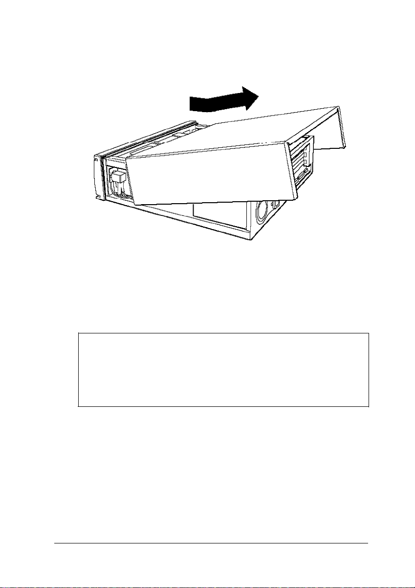
6.
Grasping the sides of the cover, lift it up at an angle and pull
it off, as shown below.
7.
Set the cover aside.
8.
Ground yourself to the computer by touching the metal
surface of the back panel.
WARNING
Be sure to ground yourself by touching the back panel of the
computer every time you remove the cover. If you are not
properly grounded, you could generate an electric shock
that could damage a component when you touch it.
Installing and Removing Options
3-3
Page 45

Replacing the Cover
When you are ready to replace the computer’s cover, follow
these steps:
1.
Make sure all the internal components are installed properly.
2.
Check all cable connections, especially those that might have
been loosened during your work.
3.
Make sure all cables are out of the way so they do not catch
on the cover.
4.
Insert the lip at the front of the cover between the front bezel
and the computer case and guide it straight down. (See the
illustration on page 3-3.)
5.
Replace the three cover retaining screws.
6.
Reconnect the computer to the monitor, printer, keyboard,
and any other peripheral devices you have. Then reconnect
the power cable to the back of the computer and to an
electrical outlet.
3-4 Installing and Removing Options
Page 46

Locating the Internal Components
As you follow the instructions in this chapter, refer to the
following illustration to locate the major components on your
system board.
external
rc..rkn
sot kl
J2:
J2L
J2E
J2E
hard dis
drive
connec
J33
J31
’
J17
option ca
connect
board
J30
k
tor
/
rd
or
._
microprocessor
\
J15
J14 J13
/
Jll
/
video
memory
r
I
\
‘keyboard
Pod
SlMM
sockets
/
/
/
I
I
I
diskette
drive
connector
.iD
JE
J4
J5
J6
J7
J8
JA
JB
JC
Installing and Removing Options
3-5
Page 47
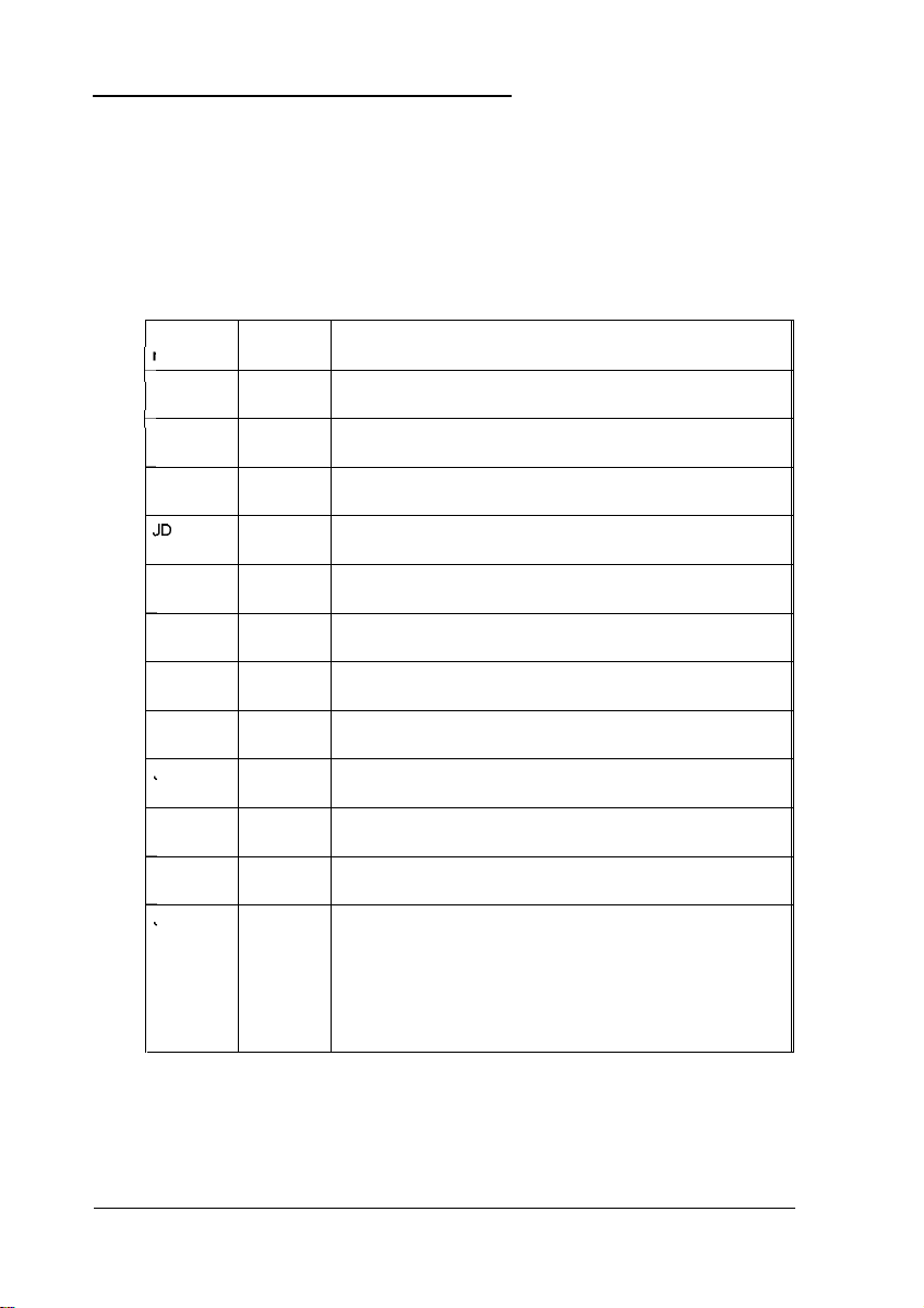
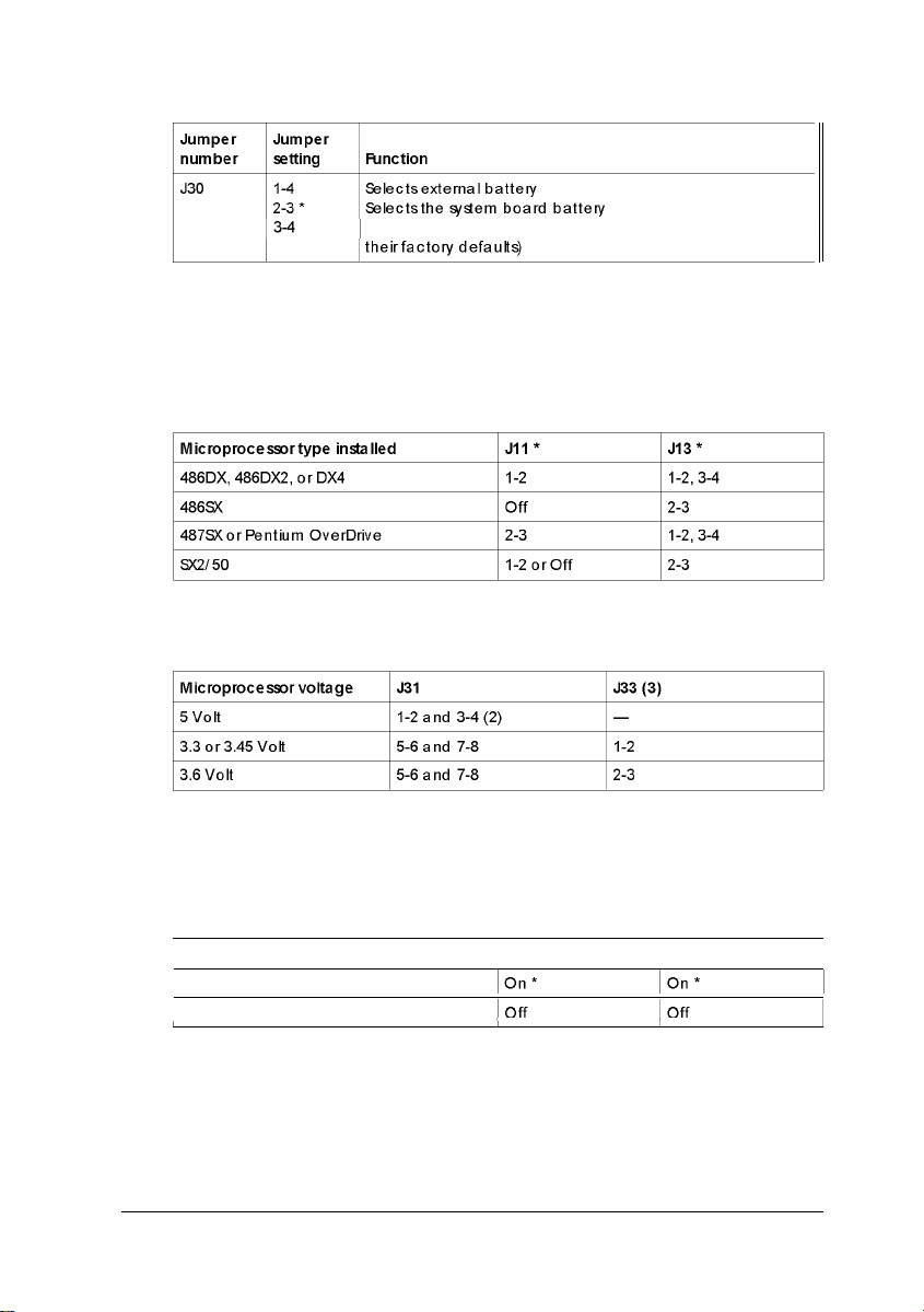
Changing the Jumper Settings
The jumpers on the main system board control certain
functions and are preset at the factory to default positions;
however, you can use the information in the following tables to
change their settings, if necessary.
Miscellaneous jumper settings
Jumper Jumper
I
lumber setting Function
c
JA
t
JB **
JC
JD
JE **
J4
J5
J6
J7
J8
J10
J17 ***
1-2 *
2-3
1-2 *
2-3
1-2*
2-3
1-2 *
2-3
1-2*
2-3
1-2
2-3 *
1-2*
2-3
1-2*
2-3
1-2 *
2-3
1-2 *
2-3
On * Enable VGA interrupt
Off Disable VGA interrupt
1-2
3-4
1-2,3-4 Microprocessor installed is a DX/40
5-6
Enables LPT (parallel port)
Disables LPT (parallel port)
Enables HDC (IDE hard disk drive controller)
Disables HDC (IDE hard disk drive controller)
Enables COMA (serial port 1)
Disables COMA (serial port 1)
Enables COMB (serial port 2)
Disables COMB (serial port 2)
Enables HDC (IDE hard disk drive controller)
Disables HDC (IDE hard disk drive controller)
Enablesgame port (J1)
Disables game port (J1)
Assigns the parallel port as LPT1 (378h-37Fh)
Assigns the parallel port as LPT2 (278h-27Fh)
Assigns serial port 1 as COM1 (3F8h-3FFh)
Assigns serial port 1 as COM3 (3E8h-3EFh)
Assigns serial port 2 as COM2 (2F8h-2FFh)
Assigns serial port 2 as COM4 (2E8h-2EFh)
Enablesthe diskette drive controller
Disables the diskette drive controller
Microprocessor installed runs at 33 MHz or 66 MHz or a
multiple of these (486SX/33, 486DX/33, 486DX2/66, DX4/100,
or Pentium)
Microprocessor installed is a 486DX/50
Microprocessor installed runs at 25 MHz or 50 MHz or a
multiple of these (486SX/25, 486DX2/50, DX4/75, or SX2/50)
3-6 Installing and Removing Options
Page 48
Miscellaneous jumper settings (continued)
Discharges CMOS memory (this resets the SETUP values to
* Factory setting
** Jumpers JB and JE must be set to the same position to enable ordisable
the hard disk drive controller
*** Default setting dependson the type of factory-installed microprocessor
Microprocessor type jumpersettings
*
Default setting dependson the type of factory-installed microprocessor
Microprocessor voltage jumper settings (1)
(1) To determine the voltage of your microprocessor, see page 3-23.
(2) Default setting
(3) The setting of J33 does not matter if you are using a 5 VoIt microprocessor
Built-in VGA controller jumper settings
Function J14 J15
Enable built-in VGA controller
Disable built-in VGA controller
I
* Default setting
Installing and Removing Options 3-7
Page 49
Note
To use an external display adapter in an expansion slot, you
must disable the built-in VGA adapter.
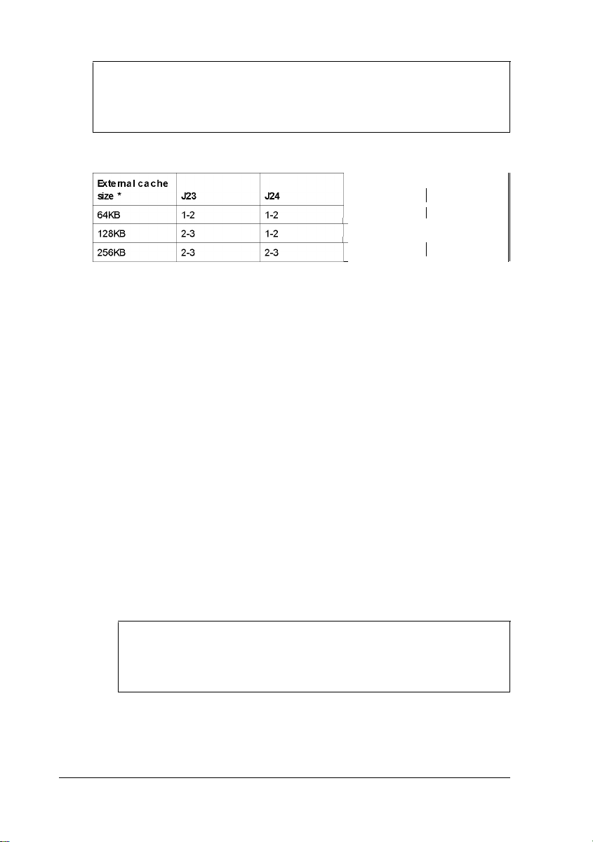
External cache size jumpersettings
J25
7,
*
If you have no externalcache, the setting of these jumpers does not
matter
Off 1 2-3
t
I
1-2
I
2-3
The jumpers listed in the preceding tables are the only ones
you may need to change; others are for service purposes only.
Setting the Jumpers
If you need to change any jumper settings, follow these steps:
1.
Refer to the illustration on page 3-5 to locate the jumpers.
2.
If the jumper you need to change is blocked by any option
cards installed in your computer, you need to remove the
card(s) to access the jumpers. See page 3-17.
3.
To move a jumper from one position to the other, use
needle-nose pliers or tweezers to pull it off its pins and
gently move it to the desired position.
1 J26
I
1-2
1 2-3
Caution
Be careful not to bend the jumper pins or damage any
surrounding components on the main system board.
3-8 Installing and Removing Options
Page 50

4.
Replace any option cards you removed; see page 3-14.
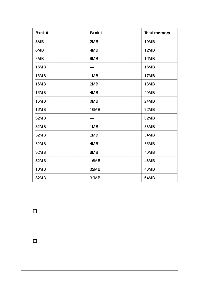
Installing Memory Modules
Your computer comes with 4MB or 8MB of memory on
memory modules-also called SIMMs (single in line memory
modules). By installing additional SIMMs, you can increase the
amount of memory in your computer up to 64MB.
There are two SIMM sockets on the main system board, and
each can contain one SIMM. You can use 1MB, 2MB, 4MB,
8MB, 16MB, and 32MB SIMMs.
The following table shows the possible SIMM configurations;
do not install memory in any other configuration. The labels on
the system board identify the sockets (Bank 0 and Bank 1) where
you should install SIMMs.
SIMM configurations
Bank
0
Bank
1
Total
memory
1MB
1MB
2MB
2MB
1MB
4MB
4MB
4MB
4MB
8MB
8MB
-
1MB
-
1MB
2MB 3MB
-
1MB
2MB 6MB
4MB 8MB
- 8MB
1MB
1MB
2MB
2MB
3MB
4MB
5MB
9MB
Installing and Removing Options 3-9
Page 51
SIMM configurations (continued)
Before you install SIMMs, check the following guidelines to
ensure that they will work properly:
0
Use only tin-plated, 72-pin, 32-bit or 36-bit, fast-page mode
SIMMs that operate at an access speed of 80ns
(nanoseconds) or faster. Be sure all the SIMMs operate at
the same speed.
0
Use the correct SIMM configuration to add the amount of
memory you want. See the table above.
3-10 Installing and Removing Options
Page 52

0
Your SIMM sockets may not look exactly like the ones in
the illustrations. If you’re not sure how to install SIMMs,
contact the EPSON Connection and ask for assistance.
Inserting SIMMs
Follow these steps to install SIMMs:
1.
Refer to the illustration on page 3-5 to locate the SIMM
sockets.
2.
Remove any option cards that may be blocking your access
to the SIMM sockets. (See page 3-17 for instructions.)
3.
Position the first SIMM at an angle over the first empty
socket in the bank you are filling, as shown below. The
components on the SIMM should face the computer’s
power supply.
Installing and Removing Options 3-11
Page 53

4.
Push the SIMM into the socket until it is seated firmly in the
slot. Then tilt it upright, as shown below, guiding the hole
at each end of the SIMM over the retaining post at each end
of the SIMM socket. If it does not go in smoothly, do not
force it; pull it all the way out and try again.
5.
Repeat steps 3 and 4 for the other SIMM, if necessary.
6.
Replace any option cards you removed. (See page 3-14 for
instructions.)
Removing SIMMs
If you need to remove SIMMs from your computer (to install
different ones, for example), follow the steps below:
1.
Remove any option cards that may be blocking your access
to the SIMM sockets. (See page 3-17 for instructions.)
3-12 Installing and Removing Options
Page 54

2.
Use your fingers or a small screwdriver to carefully pull
away the tabs that secure the SIMM at each end, as shown
below. As you pull away the tabs, the SIMM falls to the
side. Remove it from the socket.
3.
If necessary, follow the same procedure to remove the other
SIMM.
4.
Replace any option cards you removed, as described in the
next section.
Installing and Removing Options
3-13
Page 55

Installing an Option Card
This section explains how to install option cards in your
computer. Your computer has five 16-bit, ISA slots: three fulllength and two half-length.
As you install option cards, keep these guidelines in mind:
0
Check the components on your card and the system board
before deciding which slot to use. Make sure that no
components are touching or obstructing other cards or
cables.
0
When you unpack the option card, do not touch any of the
components on the circuit board or the gold-edged
connectors. Place it gently on top of its original packing
material with the component side facing up. Keep the
packing materials in case you remove the card later.
0
Before you install the card, adjust any switches or jumpers
on it, if necessary. (See the instructions that came with the
card.) Also, see if you need to change any jumper settings
on the system board. (For example, if you install a video
card, you need to disable the built-in VGA adapter.) See
page 3-6 for more information on jumpers.
3-14 Installing and Removing Options
Page 56
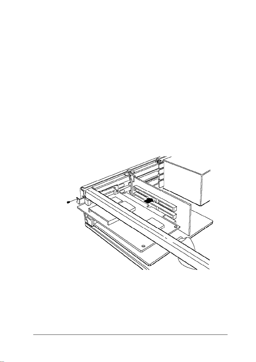
Installing a Card in a Full-length Slot
Follow these steps to install an option card in one of the
full-length slots:
1.
Remove the retaining screw securing the option slot cover
to the computer, as shown below. (Keep the screw to secure
the option card to the computer.)
2.
Slide out the slot cover and set it aside. (Store it in a safe
place in case you remove the option card later.)
3.
Hold the card along the top corners and guide it into the
slot, as shown below. (If you are installing a full-length
card, insert the front edge of the card into the
corresponding guide inside the computer’s front panel.)
Once the connectors reach the slot, push the card in firmly
(but carefully) to insert it fully. You should feel it fit into
place. If the card does not go in smoothly, do not force it;
pull it all the way out and try again.
Installing and Removing Options
3-15
Page 57

4.
Secure the end of the card to the computer with the retaining
screw.
Installing a Card in a Half-length Sot
Follow these instructions to install a card in one of the
half-length slots:
1.
Remove the retaining screw securing the slot cover bracket
Remove the bracket by lifting it straight up and out of the
small meta1 holder at the bottom.
dot coverbracket
t
/
3-16
2.
Remove the slot cover.
Installing and Removing Options
Page 58

3.
Hold the card along the top corners with the components
facing down and guide it into the slot.
Once the connectors reach the slot, push the card in firmly
(but carefully) to insert it fully. You should feel the card fit
into place. If it does not go in smoothly, do not force it; pull
the card all the way out and try again.
4.
Replace the slot cover bracket by inserting it into the small
metal holder below the option slots.
5.
Secure the slot cover bracket to the computer with the
retaining screw.
Removing an Option Card
You may need to remove an option card installed in your
computer to access components on the main system board-to
change a jumper setting, for example. You may also want to
remove a card if you no longer need it. Refer to the illustrations
on pages 3-15 and 3-16 as you follow these steps:
1.
If you are removing a card from one of the full-length slots,
first remove the retaining screw securing the option card to
the computer. Then pull the card straight out of the slot.
2.
If you are removing a card from one of the half-length slots,
first remove the slot cover bracket. Then pull the card
straight out of the slot.
3.
Set the card aside with the component side facing up.
4.
If you are not installing another option card in the empty slot,
replace the option slot cover and retaining screw.
Installing and Removing Options 3-17
Page 59

Adding Video Memory
Your computer comes with 512KB or 1MB of video memory. If
you have 512KB, you can increase your video memory to 1MB
by installing four video DRAM DIP (Dual Inline Package)
chips. The chips must be 20-pin, 256KB chips that operate at a
70ns access speed. For the memory to work properly, you must
install one chip in each empty video RAM socket on the system
board.
Additional video memory is useful for running graphicsintensive applications or for supporting video resolutions up to
1280 x 1024 in 16 colors. See Appendix A for information on
supported colors and resolutions for each amount of video
memory.
The table below lists the video DRAM DIP chips that are
approved for use in your computer.
Video DRAM DIP chip types
Manufacturer Part number
Goldstar GM71C256A-70/80
1 Fiji MB81C256A-70/80
NMBS
Toshiba
Samsung KM44C256BP-7/8
Note that your video memory sockets may not look exactly like
the ones shown here. If you’re not sure how to install video
memory chips, contact the EPSON Connection and ask for
assistance.
3-18 Installing and Removing Options
AAA1M204P-70/50
TC514256AP-7/8
I
I
I
I
Page 60
Locate the video memory sockets on the main system board,
shown on page 3-5.
If there is an option card in your way, remove it. See page
3-17 for instructions.
Caution
To avoid generating static electricity and damaging the
memory chips, ground yourself by touching the metal
surface on the inside of the computer’s back panel. Then
remain as stationary as possible while you install them.
Remove the memory chips from their package and inspect
each one. The pins should point inward at slightly less than
a 90° angle. If any of the pins are not in this position, use
your fingers or small tweezers to gently align them with the
other pins. Be careful; the pins are fragile and can break off
easily.
Position one of the memory chips over the socket as shown
below, aligning the pins on the chip with the holes in the
socket. Make sure the small notch on the end of the chip
aligns with the corresponding notch in the socket.
notches
Installing and Removing Options
3-19
Page 61
Gently press the chip halfway into the socket (to make sure
it is correctly aligned). If the chip does not go in smoothly,
remove it and try again.
When the chip is properly positioned, push down firmly on
both ends to make sure it is well-seated.
Repeat steps 4 through 6 for each of the remaining chips.
Replace any option cards you removed. See page 3-14 for
instructions.
Installing External Cache
You can install 64KB, 128KB, or 256KB of external cache on
your system.
0
To install 64KB of external cache, use eight SRAM, 28-pin,
8K x 8,20ns DIP chips, and one 8K x 8,20ns tag chip
0
To install 128KB of external cache, use four SRAM, 28-pin,
32K x 8,20ns DIP chips, and one 8K x 8,20ns tag chip
0
To install 256KB of external cache, use eight SRAM, 28-pin,
32K x 8,20ns DIP chips, and one 32K x 8,20ns tag chip.
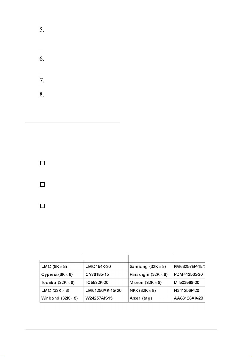
The table below lists the cache SRAM DIP chips that are
approved for use in your computer.
Cache SRAM DIP chip types
Manufacturer Part number
Manufacturer Part number
II
3-20 Installing and Removing Options
Page 62

For the cache memory to work properly, you must install chips
in the following configuration (each bank contains four cache
memory sockets):
Cache memory configurations
Bank 0 Bank 1
U23 - U26 U30 - U33
8K x 8 8K x 8
32K x
32K x
8
8
32K x
8
Tag SRAM
U34
8K x 8
8K x 8
32K x 8
Total cache
64KB
128KB
256KB
Note that your cache memory sockets may not look exactly like
the ones illustrated here. If you’re not sure how to install cache
memory chips, contact the EPSON Connection and ask for
assistance.
Installing the External Cache Chips
Follow these steps to install the external cache chips:
1.
Locate the external cache memory sockets on the main system
board, shown on page 3-5.
2.
If there is an option card in your way, remove it. See
page 3-17 for instructions.
Caution
To avoid generating static electricity and damaging the
cache chips, ground yourself by touching the metal
surface on the inside of the computer’s back panel. Then
remain as stationary as possible while you install them.
Installing and Removing Options 3-21
Page 63

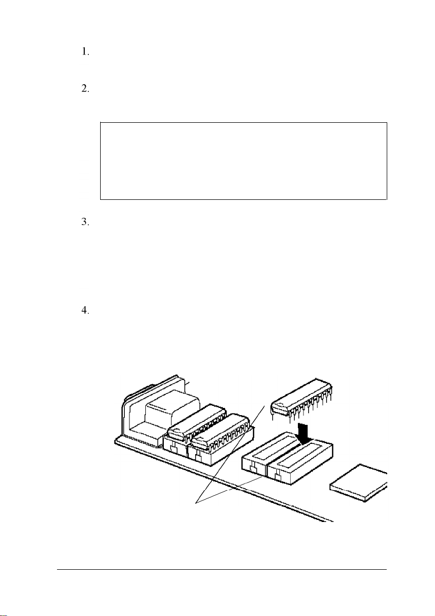
3.
Remove the cache chips from their package and inspect
them. The pins should point inward at slightly less than a
90° angle.
If any of the pins are bent or crooked, straighten them gently
with your fingers or with small tweezers to align them with
the other pins. Be careful when you do this; the pins are
fragile and can break off easily.
4.
Position one of the cache chips over the first socket as shown
below, aligning the pins on the chip with the holes in the
socket. Make sure the small notch on the end of the chip is
aligned with the corresponding notch on the socket.
U26
U25
U24
U23
5.
Gently press the chip halfway into the socket (to make sure
6.
7.
8.
Page 64

9.
Replace any option cards you removed. See page 3-14.
10. Run SETUP to enable the External Cache option and
check that the System shadow and Video shadow
options are enabled. You select these options from the
Memory Cache and Memory Shadow options on the
Advanced System Setup menu. (See Chapter 1.)
Upgrading the Microprocessor
You can upgrade your computer by replacing the
microprocessor with a faster one. The following table lists the
microprocessors, their voltages, and other components you can
install in your system.
Microprocessor upgrade components
Part
486SX/33 processor Intel 5 Volt
486DX/33 processor Intel** or Cyrix* 5 Volt
486DX/40 processor Cyrix * 5 Volt
486DX/50 processor Intel **or Cyrix * 5 Volt
486DX2/50 processor Intel **or Cyrix * 5 Volt
486DX2/66 processor Intel** or Cyrix* Intel, 5 Volt; Cyrix, 5 Volt or
SX2/50 processor Intel ** 5 Volt
DX4/75 processor Intel** or Cyrix** Intel, 3.45 Volt; Cyrix, 5 Volt
DX4/100 processor Intel** or Cyrix** Intel, 3.3 Volt; Cyrix, 5 Volt
Pentium OverDrive Intel ** 5 Volt
processor
Heat sink* Tennmax Trading Corp.® Heat sink/fan assembly** Tennmax Trading Corp. -
Manufacturer Voltage
3.6 Volt
*
A heat sink isrequired for all Cyrix DX and DX2 processors (except the
DX/33) and the Intel SX2/50 processor
** A heat sink and fan assembly are required for all Intel DX, DX2, and
Pentium OverDrive processors and for the Inteland Cyrix DX4 processors;
except the Intel DX/33, which does not need a fan assembly
Installing and Removing Options 3-23
Page 65

Note that your microprocessor socket may not look exactly like
the one illustrated here. If you’re not sure how to install your
new processor, contact the EPSON Connection and ask for
assistance.
Replacing the Processor Chip
Follow these steps to replace the processor chip :
1.
Use the illustration on page 3-5 to locate the microprocessor
on the system board. The microprocessor chip may be
inserted in a ZIF (Zero Insertion Force) socket.
Caution
Make sure you ground yourself by touching the metal
surface on the inside of the computer’s back panel before
you touch the processor chip. Then remain as stationary
as possible while you install it. Do not touch the pins on
the processor chip; handle it only by the edges of its case.
2.
If there are any option cards in your way, remove them. See
page 3-17 for instructions.
3.
Open the ZIF socket by lifting up the ZIF handle. The handle
rests under a plastic tab. Press the handle down and away
from the tab; then rotate the handle upward. This releases
the chip from the socket. The illustration on the next page
shows this handle in the released position.
4.
Gently pull the processor chip straight up and set it aside.
Note
The 486SX/25 microprocessor may be soldered onto an
adapter board that is seated in the socket. Remove the
adapter board as described above.
3-24 Installing and Removing Options
Page 66

5.
Remove the replacement chip from its package and inspect
the pins. If they are bent, do not install the processor chip.
Contact your vendor for a new microprocessor.
6.
Position the processor chip over the socket, aligning the
notched edge of the chip (marked with a dot) with pin 1 on
the socket, as shown below.
dot
pin 1
Caution
If you install the processor chip in the wrong orientation,
you may damage the chip and void your warranty.
7.
Make sure the pins in the processor chip are directly over the
holes in the socket. Then gently push the microprocessor
straight into the socket, pressing evenly on all sides.
/
If you are installing a 486 chip rather than a Pentium
OverDrive processor, you’ll see an extra row of holes
around the outside of the socket. The 486 chip does not
occupy the outside row of holes.
Installing and Removing Options 3-25
Page 67

8.
Secure the processor chip by pressing the ZIF handle back to
the closed position.
9.
Check the settings ofjumpers J11 and J13 to be sure they are
correct for the type of microprocessor you installed. You
may also need to change the setting of jumper J17 to match
the microprocessor type and operating speed.
If you installed a microprocessor with a different voltage
(check the table on page 3-23) you need to change the
settings ofjumpers J31 and J33. See pages 3-6 and 3-7 for
information on all these jumper settings.
10. If you are upgrading to a DX/ 40, DX/ 50, DX2, DX4, SX2, or
Pentium OverDrive processor, you must install a heat sink
and/or a fan, depending on the brand of processor you
installed. See the table on page 3-23 for more information.
Follow the instructions included with the heat sink if you
need to install one. If the heat sink comes with a fan, install
it using the instructions that came with the heat sink and
fan kit.
11. If you removed any option cards, replace them now; see
page 3-15 to replace a full-length card or page 3-16 to
replace a half-length card.
12. Run SETUP as described in Chapter 1 to update your
computer’s configuration with the new microprocessor
Post-installation Procedures
After you install or remove options, you must run SETUP to
update the computer’s configuration. See Chapter 1 for
instructions. Additionally, you may need to add some
commands to your configuration files. See your operating
system manual and the manual that came with your optional
equipment.
3-26 Installing and Removing Options
Page 68

Chapter 4
Installing and Removing Drives
This chapter describes how to install and remove optional
drives in your computer. You can use these instructions to
install a variety of devices, including hard disk, diskette, tape,
CD-ROM, and optical drives. Although your drive may look
different from the ones illustrated here, you should be able to
install it the same way.
Your computer can hold up to four mass storage devices. You
can install one hard disk drive using the internal mounting
bracket below the diskette drive. In the externally accessible
bays, you can install a second diskette drive or another type of
drive.
To install or remove a drive, first remove the computer’s cover
as described in Chapter 3. Then remove any option cards that
may be in your way. Once you have installed the drive, replace
any option cards you removed. See Chapter 3 for instructions.
Follow the appropriate instructions in this chapter to install
and remove drives:
0
Removing the drive mounting bracket
0
Installing a hard disk drive in the mounting bracket
0
Removing a hard disk drive from the mounting bracket
0
Installing a drive in one of the externally accessible drive
bays
0
Removing a drive from one of the externally accessible
drive bays
0
Post-installation procedures.
Installing and Removing Drives 4-1
Page 69
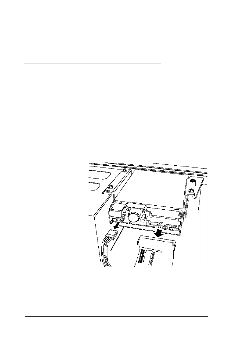
Some of the steps in this chapter may not apply for the drive
you are installing. See the documentation that came with your
drive for more information.
Removing the Drive Mounting Backet
Your computer has a 3.5-inch diskette drive installed in a
mounting bracket. (You may also have a hard disk drive
installed in the bracket.) In order to install or remove any
drives in the computer, you must first remove the drive
mounting bracket. Follow these steps:
1.
Remove the two cables from the diskette drive, as shown
below. Grasp the connectors and pull them straight out so
you do not bend the pins; do not pull on the cables. (If
necessary, remove the cables from the hard disk drive also.)
4-2 Installing and Removing Drives
Page 70
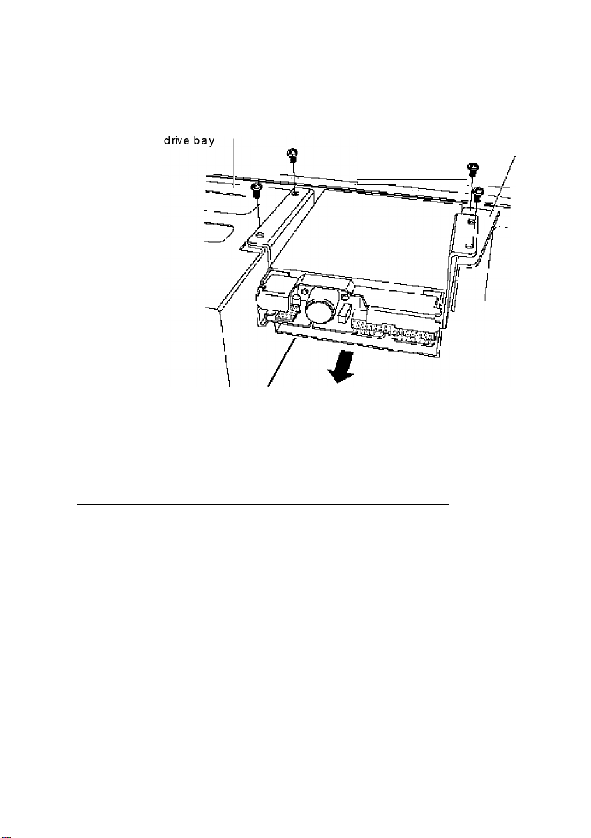
2.
Remove the screws securing the bracket to the drive bay and
brace.
brace
P /
3.
Slide the bracket away from the front of the computer and lift
it out.
lnstalling a Hard Disk Drive in the Mounting Bracket
You can install a hard disk drive below the diskette drive in the
mounting bracket after you have removed the bracket and
drive from the computer. In order to fit in this space, your hard
disk drive must be 1 inch high by 3½ inches wide. If you have
a larger hard disk drive, you can install it in one of the drive
bays (see page 4-15).
Installing and Removing Drives
4-3
Page 71

This section includes steps for the following procedures:
0
Removing the mounting frames from the hard disk drive
(if necessary)
0
Installing the hard disk drive in the mounting bracket
0
Replacing the mounting bracket in the computer
0
Connecting the drive cables.
Be sure to check the jumper settings on the hard disk drive
before you install it. If you have two hard disk drives, one must
be configured as the master (which contains the operating
system) and the other as the slave. A table of jumper settings
for high-capacity EPSON drives is included in Appendix A.
Also, you may need to know the number of cylinders, heads,
sectors, etc., if the hard disk drive auto-sensing feature in
SETUP is unable to correctly identify your drive. The hard disk
drive table used in the SETUP program is included in
Appendix A. If your drive is not listed or you need more
information, see the documentation that came with your drive
or contact the manufacturer.
4-1 Installing and Removing Drives
Page 72
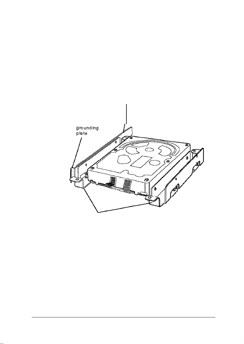
Removing the Mounting Fames
If there are mounting frames attached to your hard disk drive,
remove them before you install the drive. Follow these steps:
1.
On your drive, there may be a plastic guiderail and metal
grounding plate attached to one of the mounting frames. If
so, remove the screws securing them to the mounting
frame and remove the guiderail and grounding plate.
plastic guiderail
metal
mounting frames
2.
Then remove the two screws securing each mounting frame
to the drive and remove the frames.
Installing and Removing Drives
4-5
Page 73
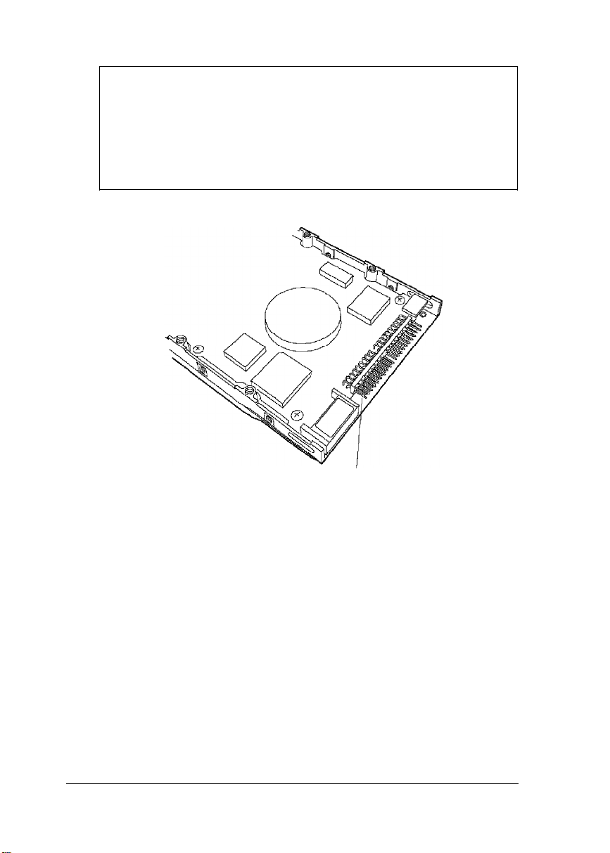
Note
Before you install the hard disk drive, turn it over so you can
see the circuit board, as shown below. Locate the side of the
drive connector containing pin 1, indicated by a “1” or “2”
printed on the board. You will need to know the location of
pin 1 when you connect the hard drive cable.
pin 1
Installing the Hard Disk Drive
Follow these steps to install the hard disk drive in the
mounting bracket:
1.
With the drive components facing down, slide the drive into
the bracket until the front of the drive is nearly flush with
the edge of the bracket.
4-6
Installing and Removing Drives
Page 74

Align the holes in the drive with the oval-shaped holes in the
2.
bracket.
Secure the drive with two or four screws, depending on the
3.
location of the holes.
Installing and Removing Drives
4-7
Page 75

Replacing the Bracket in the Computer
Follow these steps to replace the bracket in your computer:
1.
Lower the bracket with the drives into the mounting area
and slide it forward, guiding the front of the diskette drive
through the drive slot in the front panel of the computer.
2.
Make sure the holes in the bracket are aligned with the holes
in the drive bay and brace. Then secure the bracket with the
screws you removed previously.
4-8 Installing and Removing Drives
Page 76
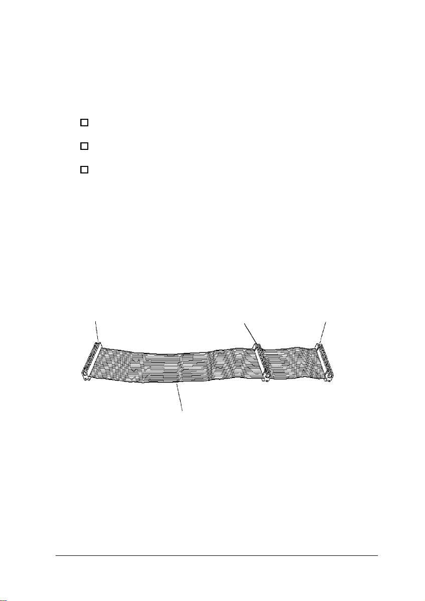
Connecting the Drive Cables
After you replace the bracket, you need to connect the cables
for both the hard disk drive and the diskette drive. This section
includes steps for the following procedures:
0
Connecting the drive ribbon cable to the system board
0
Connecting the cables to the hard disk drive
0
Reconnecting the cables to the diskette drive.
Connecting the drive cable to the system board
Follow the steps below to connect the hard drive ribbon cable
to the system board, if it is not already connected.
1.
Locate the hard disk drive ribbon cable; it is a flat cable with
three connectors that came in the box with your computer.
All the connectors on this cable look the same.
system board
connector
connector for second
hard disk drive
red wire
Installing and Removing Drives
connector for first
hard disk drive
4-9
Page 77

2.
Locate the hard disk drive connector on the system board
using the illustration below.
3.
Position the system board connector end of the cable so that
the red wire aligns with pin 1 of the connector on the
system board. There is a
“1” printed on the system board to
identify pin 1.
4-10
pin 1
4.
Make sure the holes in the connector fit over the pins; then
push in the cable connector.
Caution
If you do not correctly align the holes with the pins, you
could severely damage your system board when you push
in the cable connector.
Installing and Removing Drives
Page 78
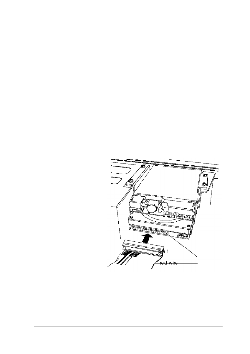
Connecting the ribbon and power cables to the drive
Follow the steps below to connect the hard disk drive ribbon
cable and a power supply cable to the drive:
1.
Locate the hard disk drive connector on the end of the hard
disk drive ribbon cable.
2.
Locate pin 1 on the drive connector. If you do not see it on
the connector casing and you did not locate it before you
replaced the drive bracket, you may have to remove the
drive and turn it over to check the circuit board. See page
4-14 for instructions on removing the drive and page 4-6 for
instructions on locating pin 1 on the drive connector.
3.
Position the connector on the cable so that the red wire
aligns with pin 1 on the drive.
Installing and Removing Drives
4-11
Page 79

4.
Make sure the holes in the cable connector fit over all the
pins; then push in the connector.
5.
Locate one of the power supply cables that lead from the
power supply. (They have multi-colored wires and a plastic
connector on the end.)
6.
Position the power supply cable connector so that its
notched corners line up with the notched corners of the
power supply connector on the hard disk drive.
4-12
7.
Make sure the holes fit over all the pins and then push in the
connector.
Installing and Removing Drives
Page 80

Reconnecting the Cables to the Diskette Drive
Refer to the illustration below while you follow these steps:
pin
red wire red wire
1.
Locate the connector on the diskette drive ribbon cable.
2.
Identify pin 1 on the drive and position the connector so that
the red wire is next to pin 1. Push in the connector.
Caution
If you do not align the cable connector correctly, you
could severely damage your drive when you push it in.
3.
Locate the power supply cable with the small connector.
4.
Position the power supply connector so that the holes fit over
all the pins and the red wire on the cable aligns with pin 1
on the drive’s power connector. Push in the connector.
Installing and Removing Drives
4-13
Page 81

Removing a Hard Disk Drive From the Mounting Bracket
Follow these steps if you need to remove the hard disk drive
from the bracket:
Disconnect the cables from any drives installed in the
mounting bracket. Grasp the connectors and pull them
straight out so you do not bend the pins; do not pull on the
cables.
Remove the screws securing the bracket to the drive bay and
brace.
Slide the bracket away from the front of the computer and lift
it out.
P
4-14
4.
Remove the screws securing the hard disk drive to the
bracket and slide the drive out of the bracket.
5.
Replace the bracket using the instructions on page 4-8.
Installing and Removing Drives
Page 82

Installing a Drive in an External Drive Bay
Your system comes with two externally accessible drive bays.
You can use these bays to install any of the following: diskette
drive, hard disk drive, CD-ROM drive, tape drive, or optical
drive.
If you are installing a diskette drive or a tape drive with a
standard 5.25-inch diskette drive connector, you can connect it
using the diskette drive cable that came with your system. If
you are installing a hard disk drive or drive with a different
type of connector, you may need to purchase a different cable.
If you are installing a second hard disk drive, you need to
check the settings of the drive’s jumpers to be sure they are
correct for your configuration. A table of jumper settings for
high-capacity EPSON drives is included in Appendix A. If your
drive is not listed or you need more information, see the
documentation that came with your drive or contact the
manufacturer.
Before you can install a drive in one of the external bays, you
must first remove the mounting bracket containing the diskette
drive (and possibly a hard disk drive). See page 4-2 for
instructions.
This section includes steps for the following procedures:
0
Attaching mounting frames to the drive (if necessary)
0
Installing the drive in the bay
0
Connecting the drive cables
Installing and Removing Drives 4-15
Page 83
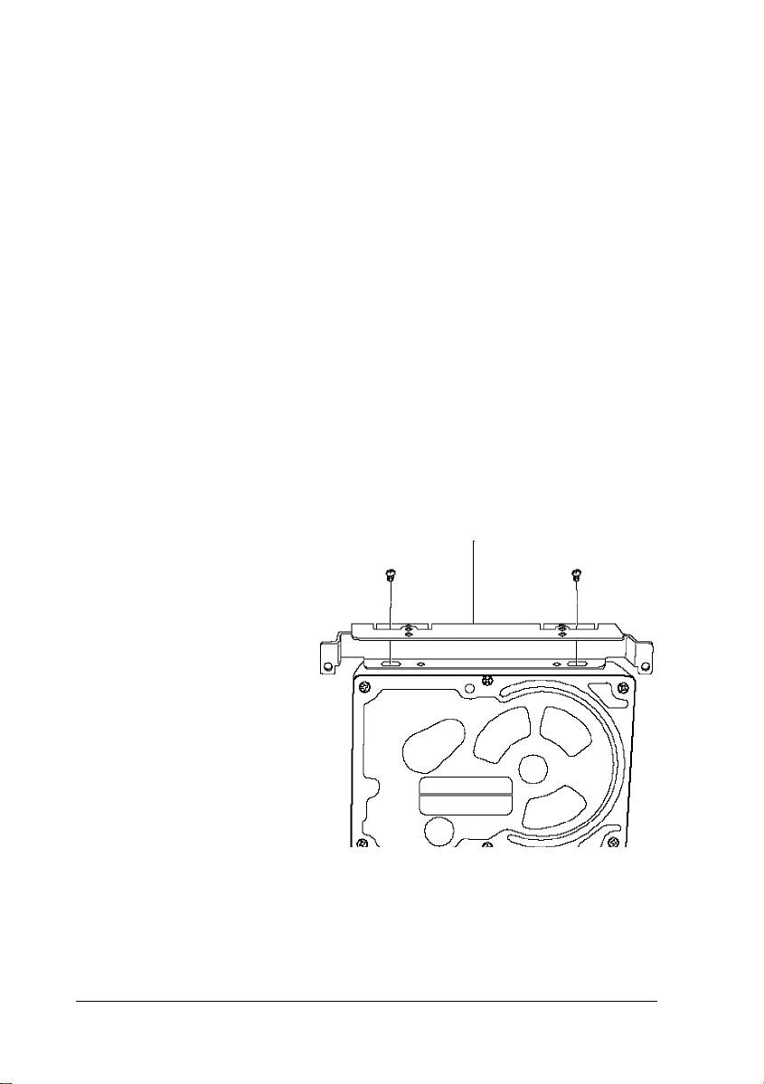
Attaching Mounting Fames to the Drive
If you are installing a 3½-inch wide drive, you need to attach
mounting frames to the drive. If you are installing a drive that
already has mounting frames on it, see if it also has a plastic
guiderail and metal grounding plate attached to it. If so, follow
step 1 on page 4-5 to remove the guiderail and grounding plate.
Then go to “Installing the Drive” on page 4-17.
Follow these steps to attach mounting frames to a drive:
1.
Locate the two mounting frames and four screws that came
with the drive.
2.
As shown below, place a mounting frame on one side of the
drive and align it so that the oval holes in the frame are
positioned over the holes in the drive. Then secure the
mounting frame to the drive with the two screws.
mounting frame
3.
Repeat step 2 to attach a mounting frame to the other side of
the drive.
4-16 Installing and Removing Drives
Page 84

Installing the Drive
Follow these steps to install a drive in the upper or lower
external drive bay:
1.
Remove the faceplate from the drive bay by pushing it out
from the inside of the computer.
Keep the faceplate in a safe place in case you remove a drive
later (or you are installing a hard disk drive).
Installing and Removing Drives
4-17
Page 85
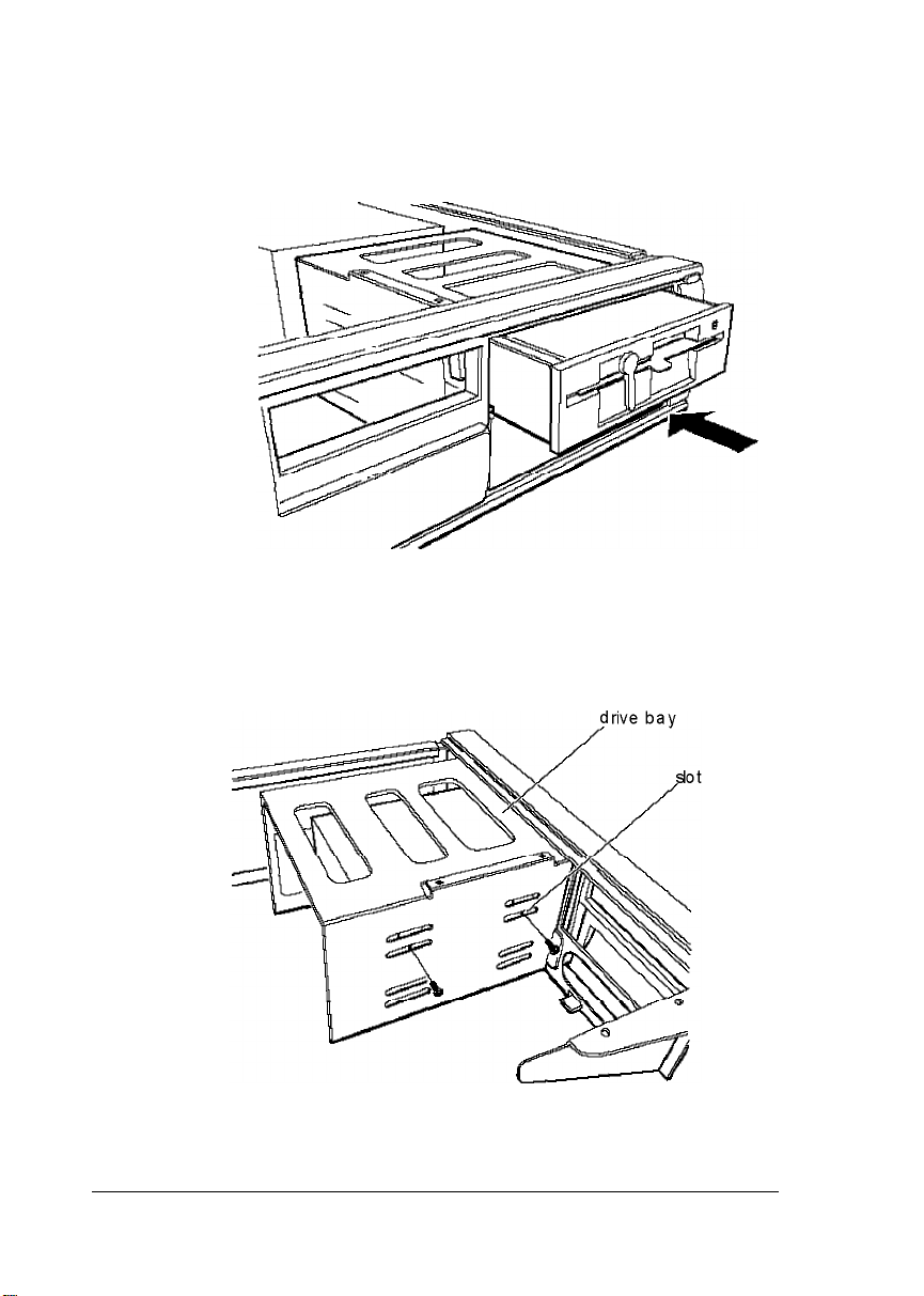
2.
Slide the drive through the slot into the bay until it is flush
with the front of the computer.
3.
Align the slots at the side of the drive bay with the mounting
holes in the drive or mounting frames. Then secure both
sides of the drive to the bay using the retaining screws.
4-18
Installing and Removing Drives
Page 86
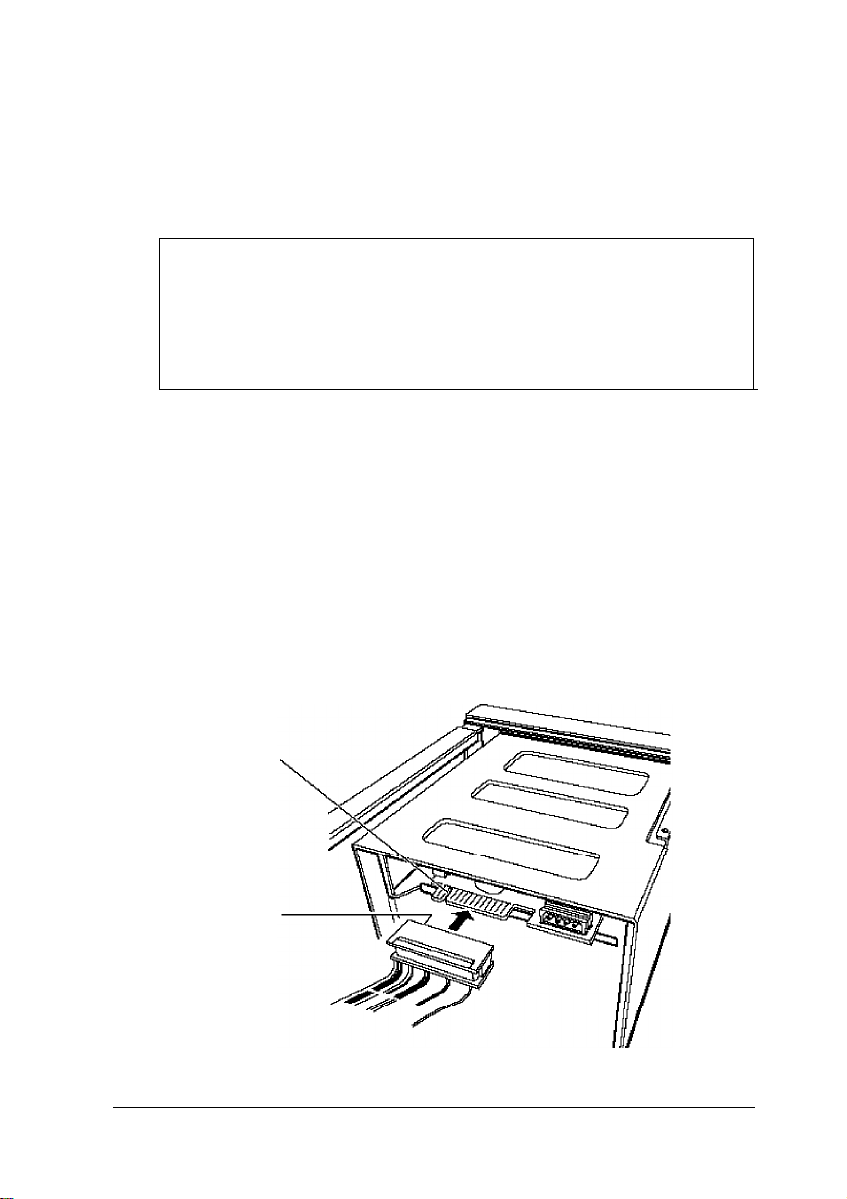
Connecting the Drive and Power Cables
If you are installing a diskette or tape drive, follow all the steps
below. If you are installing a hard disk drive, follow the
instructions on pages 4-9 through 4-12. Then go to step 5 below.
Note
If you have one hard disk drive installed in the bracket
below the diskette drive and will install and a second hard
disk drive in the external bay, you need to purchase a new
hard disk drive cable that can reach both drives.
If you are installing another type of drive, see the
documentation that came with it to connect the drive cable;
then go to step 3 below to connect the power supply cable.
1.
Locate the diskette drive ribbon cable; the connector in the
middle is already connected to the system board.
2.
If you are installing a drive with a card-edge connector, make
sure you align the key-way (the plastic divider) with the
gap in the drive connector, as shown below.
gap
key-way
Installing and Removing Drives 4-19
Page 87

If you are installing a 3.5-inch diskette drive with a header
connector, see page 4-13 for instructions on connecting the
cable.
3.
Locate one of the power supply cables that lead from the
power supply. (They have multi-colored wires and a plastic
connector on the end.)
4.
Align the notched corners of the power supply cable
connector with the notched corners of the drive’s power
connector (such as the one shown below). Make sure the
holes lit over all the pins and then push in the connector.
Caution
If you do not align the connectors correctly, you could
severely damage your drive when you push them in.
4-20 Installing and Removing Drives
notched
corners
Page 88
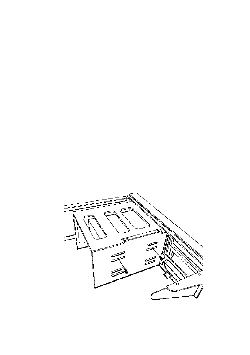
5.
If you installed a hard disk drive in one of the external bays,
replace the faceplate. Insert one side of the plate, then
gently press on the other side until it snaps into place.
After you have completed installation of the drive in the
external bay, you must replace the drive mounting bracket and
reconnect the cables. See page 4-8 for instructions.
Removing a Drive from an External Bay
To remove a drive from an external bay, follow these steps:
1.
Remove the drive mounting bracket. See page 4-2 for
instructions.
2.
Disconnect both the ribbon cable connector and the power
cable connector from the drive you are removing from the
external bay.
3.
Remove the screws securing the drive.
Installing and Removing Drives
4-21
Page 89

4.
Reach behind the drive and gently push it to the front of the
bay; then pull it out of the slot.
5.
Once you have removed the drive, replace the faceplate by
inserting one side of the plate, then gently pressing on the
other side until it snaps into place.
6.
Replace the drive mounting bracket and reconnect the cables.
See page 4-8 for instructions.
Post-installation Procedures
After you install or remove your drive(s) and replace the cover
on your computer, you need to run the SETUP program to
define your new configuration. See Chapter 1 for instructions.
4-22 Installing and Removing Drives
Page 90

Chapter 5
Troubleshooting
If you have any problems as you set up and use your
computer, refer to this chapter. You can correct most problems
by adjusting a cable connection, repeating a software
procedure, or resetting the computer.
The troubleshooting suggestions in this chapter are organized
in general categories, such as “The computer will not start.”
Within each category, a more specific problem is described
with possible solutions.
If the suggestions here do not solve the problem, contact your
Authorized EPSON Servicer or the EPSON Connection. See
“Where to Get Help” in the Introduction of this manual for
instructions.
Identifying Your System
When you request technical assistance, be ready to provide the
serial number of your computer, its system BIOS version
number, its configuration (including the type of disk drives,
monitor, and option cards), and the names and version
numbers of any software programs you are using.
Troubleshooting
5-1
Page 91

Use these guidelines to locate information about your system :
Serial number:
System BIOS version:
System
configuration:
MS-DOS version:
Software versions:
CONFIG.SYS:
Look on the back panel of the
computer to find the serial number.
Restart your system. You’ll see the
system BIOS version number
displayed on the screen during
power-on diagnostics.
Start SETUP and select the System
Summary option to see your
system‘s configuration.
VER
and press Enter to see the MS-DOS
version number.
In Windows applications, select
About from the Help menu. As
your software application starts, it
usually displays a version number
on the banner screen. Also, you can
check your software manual.
At the MS-DOS prompt, type
TYPE C: \CONFIG.SYS and press
Enter to see a listing of your
CONFIG.SYS file, which contains
system configuration commands.
AUTOEXEC.BAT:
5-2
Troubleshooting
At the MS-DOS prompt, type
TYPE C:\AUTOEXEC.BAT and
press Enter to see a listing of your
AUTOEXEC.BAT file, which
contains system startup commands.
Page 92

The Computer Will Not Start
The power light is on, but the computer does not start.
Make sure the boot options in SETUP are set to access drive A.
Then place a bootable diskette in drive A and turn on the
computer again.
Caution
If you turn off the computer, always wait at least 20 seconds
before turning it back on. This prevents damage to the
computer’s electrical circuitry.
The computer does not start and the powerlight is not lit
Make sure the power cord is securely connected to both the AC
inlet on the back panel and an electrical outlet.
The power cord is securely connected, but the computer
still does not start.
Check the electrical outlet for power. Turn off your computer
and unplug the power cord. Plug a lamp into the outlet and
turn it on.
You installed or removed system components, and now
your computer does not start.
Check to make sure you have reconnected all the internal and
external cables correctly.
You may have installed option cards that exceed the system’s
power requirements. Check the power requirements in
Appendix A.
Troubleshooting 5-3
Page 93

You may have installed a SIMM incorrectly. If the system
doesn’t detect memory, it won’t start. Check that your SIMM(s)
are securely installed in their sockets.
If you replaced the microprocessor, make sure the new
processor chip is installed correctly. Also make sure the
jumpers are set correctly and pin 1 on the chip is connected
with pin 1 on the system board. See Chapter 3.
The Computer Does Not Respond
The computer locks up.
Wait a few moments; if your computer does not respond after a
reasonable length of time, press Ctrl Alt Del. If that doesn’t
work, press the RESET button.
You may have installed SIMMs with an incorrect access speed.
Install the correct SIMMs. (See Chapter 3.)
Your system may have over-heated. Make sure you have an
adequate heat sink installed on your microprocessor, if
necessary. See Chapter 3 for more information.
You reset the computer, but it still does not respond.
Try turning the computer off, wait 20 seconds, and turn it on
again.
Your computer suddenly stops operating.
You may have overloaded the power supply. See your option
card manual(s) for the power requirements for your option
card(s). Then check Appendix A to see if you have exceeded
the option slot power limits.
5-4
Troubleshooting
Page 94

Keyboard Problems
The screen displaysa keyboard error message when you
turn on or reset the computer.
Make sure the keyboard is securely connected to the keyboard
port and not the mouse port. Although these ports look alike,
they cannot be used interchangeably.
Nothing happens when you type on the keyboard.
The Lockout Timer may be set in SETUP. This option
inactivates the keyboard for a specified period of time after the
system returns to an active mode from a low-power standby
mode. This delay gives Energy Star compliant monitors the
time they need to return to an active mode. Wait a few seconds
and try again.
See “The Computer Does Not Respond,” above
The cursor keys on the numeric keypad do not work
properly.
If the Num Lock light in the upper right corner of the keyboard
is lit, press NumLock to turn off the function.
Mouse Problems
Yourmouse isn’t working properly or you see an auxiliary
device error message.
Make sure the mouse cable is securely connected to the MOUSE
port and not the keyboard (K/B) port. Also make sure you
installed the mouse driver correctly (if necessary). See the
documentation that came with your mouse for instructions.
(Windows automatically installs a mouse driver when you
install the program.)
Troubleshooting
5-5
Page 95

Monitor Problems
There is no display on the screen.
Check that the monitor’s power switch is on and that its power
light is on.
Also, the computer may be in low-power standby mode. When
you press a mouse button or a key on the keyboard, see if the
monitor displays an image.
The power light is on, but you still do not see anything on
the screen.
Press a mouse button or a key on the keyboard to see if the
computer is in low-power standby mode. Also, check the
brightness and contrast controls.
If you still do not see anything on the screen, make sure the
monitor is securely connected to the computer.
If you installed a display adapter card, make sure your monitor
type matches the card type. Also be sure you set the correct
display type in SETUP (see Chapter 1) and that the main
system board jumpers are set correctly (see Chapter 3).
If you are running an application program, see if you need to
set up the program for the type of monitor and display adapter
you have. Also make sure you are using the appropriate
monitor and display adapter for your software.
The powerswitch is on but the powerlight is not on.
If the monitor is Energy Star compliant, it may be in low-power
standby mode. Press a mouse button or a key on the keyboard
to activate the monitor.
Turn off the monitor’s power, wait five seconds, and turn it
back on.
5-6
Troubleshooting
Page 96

If the light still does not come on, check the electrical outlet for
power. Turn off your monitor and unplug it from the outlet.
Then plug a lamp into the wall outlet and turn it on. If the light
turns on, your monitor may be faulty.
Diskette Problems
You see a diskette error message.
Reinsert the diskette, making sure you insert it all the way. If
the drive has a latch, turn it down to secure the diskette.
Also, check to see that you have inserted the right type of
diskette in the drive. For example, make sure you are not
inserting a high-density diskette in a double-density drive.
If reinserting the diskette does not solve the problem, insert the
diskette in another diskette drive of the same type. If you can
read the diskette in a different drive, your drive may be faulty.
The diskette is the tight type, but you still see an error.
Check that the diskette is not write-protected, preventing the
drive from writing to the diskette.
Make sure the diskette is formatted. See your operating system
documentation for instructions on formatting diskettes.
The system may have the Diskette Access option in
SETUP enabled. If you entered a User level password when
you started the system but this option is set to a Supervisor
level, you see an error when you access the drive.
You may have a defective diskette. Try copying the files from
the bad diskette to a new diskette.
Troubleshooting
5-7
Page 97

Something is wrong with the data in the files
If you are using MS-DOS, run CHKDSK to repair the files. You
may also be able to use special utilities or diagnostics to solve
this problem.
Diskette Drive Problems
A newly installed diskette drive is not working properly.
Make sure you have installed the drive correctly and check all
the cable connections.
You see a diskette drive error when you start your computer.
Run the SETUP program and configure your system for the
correct type of diskette drive.
The diskette drive is making loud or unusual noises
Contact your Authorized EPSON Servicer or the EPSON
Connection.
Hard Disk Drive Problems
A newly installed hard disk drive is not working properly or
its performance is not what you expect.
Make sure you have installed the drive correctly and check all
cable connections. Also, check the jumper settings on your
drive.
Some hard disk drives do not support the Energy Star features
on your system. You may need to disable these features in
SETUP.
5-8
Troubleshooting
Page 98

You see a hard disk drive error when you start your system.
Run SETUP and check that your system is auto-sensing the
correct drive type. If auto-sensing is enabled and SETUP
displays information that does not match your drive, you may
need to define your own drive type. See Chapter 1.
Make sure the jumpers on the system board are set correctly.
Jumpers JB and JE enable or disable the IDE hard disk drive
controller. See Chapter 3 for jumper information.
Make sure the jumpers on the hard disk drive are set correctly.
See the documentation that came with the drive for more
information.
You ate unable to store data on the hard disk drive.
If the hard disk drive has been in low-power standby mode,
make sure the drive has had time to achieve its full operating
speed before you try to write data to it.
If your drive was not configured, make sure you have
partitioned and formatted it correctly for your operating
system. See your operating system manual for instructions.
Also, make sure your hard disk drive has been physically
formatted by the manufacturer. (All EPSON-supplied drives
are physically formatted at the factory.) If it has not been
physically formatted, use the format utility that came with the
drive to format it before you partition it or install the operating
system. (Note that a physical format is different from
software-based formatting commands, such as the MS-DOS
FORMAT command.)
Troubleshooting
5-9
Page 99

You have been using your hard disk drive successfully for
some time but notice a reduction in performance.
The data on the disk may have become fragmented. Back up all
your data and use a disk compaction utility to reorganize the
files on your disk.
If you cannot access data on your hard disk or you are seeing
read/ write errors, the disk may have a physical problem.
Contact your Authorized EPSON Servicer or the EPSON
Connection.
Password Problems
You have forgotten your password.
You must discharge your CMOS memory. To do this, you
need to change the setting of jumper J30 to position 3-4. See
Chapter 3 for details on changing the jumper setting.
After you have changed J30, restart your system, leave it on for
a few seconds, then turn it off again. This resets the SETUP
values to their factory defaults. Both the Supervisor and the
User passwords are disabled.
Set J30 back to position 2-3. Then turn the computer on again.
Use SETUP to set a new password, if you want one.
5-10
Troubleshooting
Page 100

Software Problems
The application program does not start.
Check that you are following the correct procedure for starting
the program and that it is installed correctly. If you do not have
a hard disk, make sure the correct diskette is in the diskette
drive. If you need help, contact your software manufacturer.
The application program is having trouble reading a key
disk.
You may be running an application that requires a slower
processor speed. Change your processor speed using the
keyboard commands described in Chapter 2.
The application program is having trouble reading from or
writing to the hard disk drive.
If you have enabled the Fixed Disk Timeout option in
SETUP, your application may be timing out during the few
second delay when the hard disk drive returns to its operating
speed after being in standby mode. Disable this option in
SETUP (see Chapter 1).
Yourapplication haslocked the computer, making it
unresponsive to keyboard commands
Reset the computer and try again. If resetting the computer
does not help, turn it off, wait 20 seconds, then turn it on again.
Some software, like OS/ 2®, UNIX®, or NetWare®, needs a
minimum of 8MB to 16MB of RAM to work correctly. Check
your software documentation for the minimum memory
requirements. If necessary, add additional memory using the
instructions in Chapter 3.
Troubleshooting
5-11
 Loading...