

Page 1

ATH2 Owner’s Manual
SAFETY! SAFETY!
1) Read and understand instructions and heed warnings before beginning installation.
2) Mount rail securely. The lens is heavy, and requires a secure and stable surface. Fasteners in
sheetrock alone are not safe. Reciprocal lens motion can and will work them loose. Use a
board, plate, or projector mount fixed to ceiling joists or studs.
3) Ladder caution: Exercise extreme caution when working on a ladder. Do not work directly
above another person, particularly a child. Plan all work carefully. Accidentally dropping a
drill, hammer, or the lens assembly can cause serious bodily injury.
4) Unexpected lens mo vement: Anticipate all lens motion. A malfunctio n can cause the lens to
move unexpectedly. While on a ladder, do not stand in direct path of lens in case of
unexpected or accidental movement. Disconnect power when installing, working on, or
repositioning the lens.
5) Indoor use only: Do not install lens in a wet or moist environment, or where the mechanism
will be exposed to extreme or external weather conditions.
6) Object and liquid entry: Never pour any liquid or push any object into the enclosure.
7) Power Sources: The power adaptor is intended for 100- 220 volt, 50-60 cycle AC power only.
8) Power Cord: Do not subject power cord to conditions which will wear through or cut the
insulation. Avoid excessive tension or chafing of the cord.
9) Service: Do not service the motor drive or electronics. There are no user serviceable parts.
Contact your dealer. Send only to a factory approved facility.
This device complies with part 15 of the FCC rules. Operation is subject to the following two conditions:
(1) This device may not cause harmful interference, and (2) this device must accept any interference
received, including interference that may cause undesired operation
©Panamorph Inc January 2009 – All rights reserved Page 1
Page 2

ATH2 Owner’s Manual
January 2009 Edition –
Printed January 2009
©Panamorph Inc.
All rights reserved
©Panamorph Inc January 2009 – All rights reserved Page 2
Page 3

ATH2 Owner’s Manual
.
1 Introduction
Congratulations, and thank you for purchasing a quality Panamorph product. Your ATH2 lens motor/sled is
outfitted with a custom mechanism designed exclusively for use in the home theater environment. No oil or
liquid based lubricants are used to assure the maximum cleanliness for optical components. Both lens and
drive will provide years of maintenance free service. The Panamorph system is built and tested in the USA
to the strictest quality standards and certifications.
Features and benefits:
Easy, straight forward installation and operation
Machined, high grade, anodized aluminum components
Repeatable precision positioning system
Flexible mounting options allowing table or ceiling mount
Speed selector for high or low speed operation
Configurable “lens in” position
Extra external IR sensor for remote mounting (if needed)
Input 12V jack for automatic lens trigger
Output 12V jack for screen masking trigger
Non mechanical long life optical stop sensors
Dry operating precision linear bearings
Custom built, high precision, low current NEMA 23 stepper motor
Custom built, low noise stepper drive circuitry and firmware
Endurance tested to over 2,000,000 traversals
8 button long range remote control (up to 50 feet) with discrete functions
Backlit logo with on/off lighting control
Reversible logo plates
Completely maintenance free
USA built and tested
FCC, CE, and UL certified
©Panamorph Inc January 2009 – All rights reserved Page 3
Page 4
ATH2 Owner’s Manual
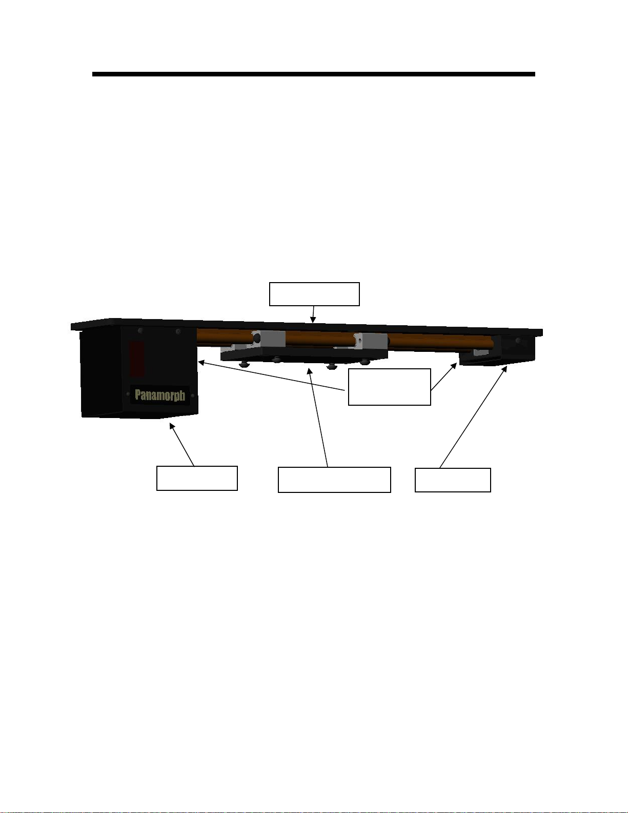
2 Motorized Lens Sled Parts
During installation, this manual will refer to the motor side, or the pulley side of the mechanism. Refer to
the picture below for a description. As shipped from the factory the “lens-in” side of the unit is at the motor
end. Depending on the projector, “Lens in” will either be on the motor or the pulley side of the sled. See
Chapter 6 – Setup, to configure the “lens in” orientation of the sled to the pulley side.
Mounting bar
Motor side
Optical
sensors
Lens adaptor plate
Pulley side
©Panamorph Inc January 2009 – All rights reserved Page 4
Page 5

ATH2 Owner’s Manual
3 Plan your installation
The lens assembly may be mounted in one of two ways:
1) To the ceiling or projector mount above the projector
2) To a shelf or table below the projector
When attaching motor assembly to the ceiling, use a board, plate, or lens enabled projector mount
attached to the ceiling joists or studs. Sheetrock embedded fasteners will work loose with repeated lens
movement causing the mechanism to fall, resulting in possible severe injury. The Panamorph AKX or
AKCPro mounting kit is highly recommended.
Changing Orientation of Logo Plate (optional)
As shipped, the lens sled is configured for ceiling mounted operation. As such, the logo reads right side up
with the mounting bar on top. If you are using the sled in a table or shelf mounted configuration, you may
optionally turn the logo around so that it is right side up with the mounting bar below the projector.
To reverse the logo, remove the 4 screws securing the motor housing cover. Lightly spread the sheet metal
cover and lift it off. Once removed, you can easily access the logo plate. Remove the two small plastic
screws securing the logo plate, turn the plate around, and re-install the screws. Lightly tighten the screws,
as the threads are plastic. Re-install the motor cover housing using the original screws. Make sure the fiber
optic light pipe connector is completely inside the housing before reinstalling motor hou sing screws.
An alternative to reversing the logo plate is to turn off the back light, thereby rendering the logo
inconspicuous. Simply press the PANEL OFF button to accomplish this.
4) Reinstall 4
cover screws
3) Turn plate
around replace 2
logo plate screws
©Panamorph Inc January 2009 – All rights reserved Page 5
1) Remove 4
cover screws
and remove
cover
2) Remove 2
logo plate screws
Page 6

ATH2 Owner’s Manual
4 Mount Sled to Projector Plate
When using the Panamorph AKX or AKXPro system follow directions supplied with the mounting
plate and skip to Chapter 5 – Attach Lens Bracket. Otherwise, follow the directions below for a
custom fabricated mount.
When building a custom mount, mark screw locations using only the sled as shipped, without the lens
and/or the lens bracket in place. Do not rely on fasteners embedded in sheetrock alone. Reciprocal lens
movement will work them loose, and cause the mechanism to fall. Mount the ATH2 to a plate, board, or
lens enabled projector mount ultimately affixed to ceiling joists for safety.
Recommended procedure:
1) Align mounting to center line of lens
Before beginning, the projector must be correctly focused with the zoom and iris set in their viewing
positions for 16:9 or 4:3 viewing depending on the native mode of the projector. This will determine
correct positioning of the front of the projector lens. Hold the motor/sled up to the projector and decide if
the LENS IN position will be at the motor housing or pulley housing side.
Measure 2 1/8 inches from the front of the focused projector lens, and lightly draw a line parallel to the
front of the lens. Mark the center line of the projector lens along this parallel line. Now, line up the back of
the mounting bar to the parallel line just marked. Align the center of the projector lens to the following
locations as appropriate:
“Lens In” position at motor housing side – center of lens is 7.25” from end of mounting bar
“Lens-In” position at pulley housing side – center of lens is 5.375” from end of mounting bar
Refer to dimensioned drawing at back of this manual for clarification (page 15).
Mark the six hole locations using the mounting bar itself as a template. Drill the holes for secure (never use
sheetrock inserts) fasteners.
2) Secure mounting bar
As the mechanism and lens are heavy, make sure the fasteners, and surface are extremely secure.
Remember that the sled motor will be starting and stopping a heavy weight thousands of times through
normal use. Ceiling mounted lenses require a secure and flat surface. Sheetrock anchors alone are
insufficient and will work loose over time causing potential injury. Secure the mounting bar to a plate,
painted board, or lens enabled projector mount securely affixed to the studs or ceiling joists. Periodically
re-check the security of the mounting. Use of a commercial mounting system designed for anamorphic
lenses is highly recommended. Use all six screw holes, and tighten fasteners securely. Vibration from the
motor and reciprocal lens movement will loosen any fasteners that are not absolutely tight and secure from
vibration.
©Panamorph Inc January 2009 – All rights reserved Page 6
Page 7

ATH2 Owner’s Manual
5 Attach Lens Bracket
1)Attach lens bracket to adapter plate
Remove the bracket mounting screws and hex key from the parts package and use them to attach the
Panamorph lens bracket supplied with the ATH2. Snug up the bolts with the supplied hex key. Maintain
even pressure on each bolt. The angled portion of the bracket fork faces the rear of the mechanism. Do not
attach the lens or power up the sled just yet! Adjustment and alignment are easier without the lens for
now.
Front of unit
Bracket mounting
screws
©Panamorph Inc January 2009 – All rights reserved Page 7
Page 8

ATH2 Owner’s Manual
6 Setup
1) Power up the sled and set LENS IN position
Bright lights, particularly direct sunlight shining into the optical sensors at either end of the sled will
prevent the sled from operating normally. Test the sled under normal or low lighting conditions. Now
slide the lens into the middle of the sled before powering up. Plug the power adaptor into an AC outlet,
then into the back of the unit. Put two AAA batteries in the battery compartment of the hand held remote
control. Back away from the lens or descend the ladder. Hit ON, wait for the LED to flash 3 times, and
then hit the LENS IN button on the remote. The lens sled will now position itself into the factory default
LENS IN position. The edge of the adaptor plate will land approximately ½ inch from the motor housing
side of the sled.
If the bracket is not in front of the projector lens, you will need to change the “lens in”position so that
“lens in” is at the pulley side of the mechanism. Simply press the LENS OUT button on the remote, and
wait for the bracket to move in front of the projector lens. Press and hold the LENS OUT button again,
until the lens begins to move, and release. The sled will confirm the new setting by moving the bracket
away from the projector lens, to the new LENS OUT location (now the motor side). You have now reprogrammed the sled to reverse the “lens in” side.
2) Verify centering
Press LENS IN and observe where the lens stops. If needed, you may make small adjustments (+ or – ¼
inch) to the lens bracket after disconnecting the power, by loosening the screws and sliding the bracket to
the left or right as needed to achieve centering. Reconnect the power and check your work. The optical
sensors will stop the edge of the lens adaptor plate approximately ½ inch from the housings on either side
of the sled. It will always stop at exactly the same spot. You may use this gap on the motor or the pulley
side for fine adjustments.
Gap
©Panamorph Inc January 2009 – All rights reserved Page 8
Page 9

ATH2 Owner’s Manual
3) Attach anamorphic lens to bracket
Attach the UH480 lens to the bracket using the lens knobs supplied with the lens. Adjust the anamorphic
lens vertically for correct alignment. See the instructions accompanying the UH480 attachment kit for fine
tuning the lens position and screen image. Instructions are downloadable from http://www.panamorph .com.
When the image is correct, tighten the knobs against the bracket. Test run LENS IN and LENS OUT using
the remote. It is important to note that the lens is vertically oriented to the projected beam coming out of
the bottom half of the projector lens (assuming ceiling mount). Usually, the top of the anamorphic lens
will lie somewhere near the center of the projector lens as shown below.
Note
alignment of
top of lens
Lens knob
4) Configure Operating Speed (optional)
The lens sled has two operating speed modes – FAST and SLOW. FAST is the default from the factory,
and is ideal under most circumstances. The slow mode reduces the forces exerted by the lens on the
mounting system by accelerating and decelerating very slowly, and by limiting the top speed of the lens as
it traverses the sled. Some users set the speed to SLOW when used in conjunction with screen masking
systems to synchronize mask traversal time to sled traversal time.
CONGRATULATIONS!!!! YOU ARE NOW READY TO
ENJOY FULL WIDESCREEN CINEMA IN YOUR HOME
THEATER
.
©Panamorph Inc January 2009 – All rights reserved Page 9
Page 10

ATH2 Owner’s Manual
7 Lens Sled Operation
The status LED indicator behind the plastic window on the ATH2 will flash three times when the unit is
powered ON, and flash when any remote button is pressed. When in standby the LED is off. Once turned
ON, the unit remains in the ON state, even if the power fails and is reinstated.
Buttons:
OFF – Puts the ATH2 in standby mode.
ON –Turns the ATH2 ON.
LENS OUT – Moves to the LENS OUT position.
LENS IN –Moves to the LENS IN position.
PANEL OFF – Switches the logo back light and status LED
off.
PANEL ON – Switches the logo back light and status LED
on.
SLOW – Sets the acceleration/deceleration and maximum
speed for slow (low inertia) traversal.
FAST – Sets the acceleration/deceleration and maximum
speed for rapid traversal.
Note: If LENS IN does not position the lens to the correct
side of the mechanism, see Chapter5 (middle of page 8) to
reverse orientation.
Users of Pronto compatible devices may download an IR
code hex file from the following URL:
http://www.remotecentral.com
The Panamorph ATH2 will appear in the FILES section of
the website as Panamorph M380.
©Panamorph Inc January 2009 – All rights reserved Page 10
Page 11

ATH2 Owner’s Manual
00
8 Rear Panel –Triggers
To use the automatic lens trigger, with a projector or scaler equipped with an external 12V lens trigger, use
a standard double-ended 3.5 mm (1/8 inch) male mono or stereo jack cable. Simply plug the cable into the
projector or scaler lens trigger jack, and then into the ATH2 +12V Trigger In jack. Follow projector or
scaler instructions to configure the lens trigger to send the lens in when the vertical strectch aspect ratio is
selected on the projector. Any voltage change (12V to 0V, 0V to 12V) will automatically turn the sled on
causing it to move to the designated position. When using the trigger, the remote control is not required
after configuration.
NOTE: Plugging a live trigger in will automatically turn the sled on and cause it to move. Stand clear of
the lens path when inserting the trigger cable.
The
Trigger In (tip positive) operates as follows:
+12V LENS IN
0V LENSOUT
NOTE: The input trigger jack may be temporarily overridden by the remote control. When the next
change of voltage at the trigger occurs (up or down), the projector or scaler will take control of the sled.
Optionally, you may use the +12V Trigger Out jack on the rear of the device to control motorized screen
masking. The output jack is toggled to +12V whenever the sled is in the LENS OUT position. The output
trigger voltage is toggled when the lens begins traversal so that masking and lens movement may be
overlapped. Maximum output current is 100mA which is sufficient for most masking screen control
modules. The sled is configured to trigger the masking in when the lens it out, so the signal is opposite the
input trigger.
Trigger Out jack (tip positive) is intended to for use with external masking screens, It operates as
The
follows:
+ 0V Lens is moving to, or is in the LENS IN position. Note this is the inverse of the input signal.
+12V Lens is moving to, or is in the LENSOUT position. Note this is the inverse of the input signal.
The equipment control port is used by OEM projector manufacturers for custom control options. It can be
ignored by installers.
+9v to +12v In
+12v Trigger Out
+12v Trigger In
Auxiliary In
To screen
masking
controller, max
mA
1
From
projector or
OEM equipment
scaler trigger,
min 3.5uA
control port
©Panamorph Inc January 2009 – All rights reserved Page 11
Page 12

ATH2 Owner’s Manual
9 Cleaning & maintenance
The Panamorph system is completely maintenance free. It will deliver many years of trouble free service as
delivered from the factory.
Clean the outside of the lens prisms occasionally with glass cleaner and an appropriate lens cloth. We
recommend cleaning the lens while in the path of the projected beam to clearly observe the surface.
Clean the metal components with a damp cloth, taking care not to drip any water into the enclosure.
The ATH2 internal drive is permanently lubricated. Keep the rail linear bearing clean, dry, and contaminant
free. In case of accidental soiling (i.e. spilled soda), clean all contaminants with water, and finally wipe
down with denatured alcohol. The drive mechanism relies upon a clean rail to operate smoothly. The linear
bearing, and all enclosed bearings are constructed of specialized material to self lubricate. Lubricants will
gum up the mechanism, and possibly produce a film across the projector and lenses.
Never use lubricants of any nature on any part of the mechanism.
©Panamorph Inc January 2009 – All rights reserved Page 12
Page 13

ATH2 Owner’s Manual
10 specifications
Electrical Characteristics
Model ATH2 motorized sled
Power supply 100-240VAC, 50-60 cycles
Power Supply Output 12V DC, .8-1.5A (depending on supply in use)
Operating Voltage 9 -18V DC, .5-1.5A
Operating current draw Avg : 650mA
Standby current draw 60mA
Trigger jacks 3.5 mm mono or stereo jack, 12V tip positive,
100mA max output, 3.5mA minimum trigger input
Auxiliary jack 2.5 mm stereo jack for special OEM control
Remote 3oz, IR emitter
IR Range 50ft from IR sensor
IR Carrier Frequency 38 kHz
Batteries 2 AAA
Certification FCC, CE (ATH2 motor drive unit)
UL Class II (power supply only)
Design Life Greater than 2,000,000 rail traversals
Physical characteristics
Weight 7 lbs.
Dimensions See accompanying drawings
©Panamorph Inc January 2009 – All rights reserved Page 13
Page 14

ATH2 Owner’s Manual
Dimensions
Center of lens
motor side
Center of lens
pulley side
©Panamorph Inc January 2009 – All rights reserved Page 14
Page 15

ATH2 Owner’s Manual
©Panamorph Inc January 2009 – All rights reserved Page 15
Page 16

ATH2 Owner’s Manual
Warranty
Panamorph Inc, warrants this product to be free of defects in original
workmanship and material for a period of twenty four months from the date of
manufacture. During this period, a defective unit may be repaired or replaced,
at the discretion of Panamorph, Inc., by returning it in its original packaging
with a copy of your receipt. This warranty does not cover damage resulting from
tampering, lack of prudent care, accident or misuse (including contravention of
cautions stated in the instructions), or any cosmetic damage not reported within
15 days of purchase. All liability for damage is limited to the cost of the product
and does not include incidental injury or peripheral damage to other equipment,
persons, or property. Panamorph Inc. is not responsible for personal injury
resulting from faulty installation. A service charge may be applied to any
returned product requiring cosmetic attention, or to the repair of any damage
not covered under this warranty
©Panamorph Inc January 2009 – All rights reserved Page 16
 Loading...