

Page 1

2HDD
OI-R02
User’s Manual
400948800
1
Page 2

About the Symbols
Following symbols are used in this manual.
CAUTION
Failure to observe a CAUTION may result in personal injury, or in
damage to equipment or other property.
Note
Notes have important information and useful tips on the operation
of your printer.
Notice
1. All rights reserved. Reproduction of any part of thi s manual in any
form whatsoever without EPSON’s express written permission is
forbidden.
2. The contents of this manual are subject to change without notice.
Please contact us for the latest information.
3. All efforts have been made to ensure the acc uracy o f the co ntents of
this manual. However, should any errors be detected, EPSON
would greatly appreaciate being in formed of them .
4. The above notwithstanding, EPSON can assume no responsibility
for any errors in this manual or their consequences.
5. Neither Seiko Epson Corporation nor its affiliates shall be liable to
the purchaser of this product or third parties for damages, losses,
costs, or expenses incurred by the purchases or third parties as a
result of: accident, misuse, or abuse of this product or
unauthorized modifications, repairs, or alterations to this product,
or (excluding the U.S.) failure to strictly comply with Seiko Epson
Corporation’s operating and maintenance instructions.
6. Seiko Epson Corporation shall not be liable against any damages or
problems arising from the use of any options or any consumable
products other than those designated as Original EPSON Products
or EPSON Approved Products by Seiko Epson Corporation.
2
Page 3

Contents
1. Outlinne . . . . . . . . . . . . . . . . . . . . . . . . . . . . . . . . . . . . . . . . . . . . . . . . . . . . . . 1
2. Unpacking . . . . . . . . . . . . . . . . . . . . . . . . . . . . . . . . . . . . . . . . . . . . . . . . . . . . 1
3. Installation. . . . . . . . . . . . . . . . . . . . . . . . . . . . . . . . . . . . . . . . . . . . . . . . . . . . 2
Installing the HDD . . . . . . . . . . . . . . . . . . . . . . . . . . . . . . . . . . . . . . . . . . . . 2
Installation in the IM-300 . . . . . . . . . . . . . . . . . . . . . . . . . . . . . . . . . . . . . . 5
4. Precautions When Usig . . . . . . . . . . . . . . . . . . . . . . . . . . . . . . . . . . . . . . . . . 8
5. List of Specifications . . . . . . . . . . . . . . . . . . . . . . . . . . . . . . . . . . . . . . . . . . . 9
HDD which can be installed. . . . . . . . . . . . . . . . . . . . . . . . . . . . . . . . . . . . 9
Environmental Specifications. . . . . . . . . . . . . . . . . . . . . . . . . . . . . . . . . . . 9
Connector Specifications . . . . . . . . . . . . . . . . . . . . . . . . . . . . . . . . . . . . . . 10
(C) SEIKO EPSON CORPORATION 1998
3
Page 4

4
Page 5
Outline
This product makes it possible to install one or two hard disk drives
(hereafter, HDD). When installing two HD D, be sur e to set the HDD as
the first drive (Master) or second drive (Slave). Setting as the first or the
second HDD is done by setting the jumpers on the HDD.
If a pre-formatted HDD is installed as the second HDD, the first drive
becomes drive C and the second drive becomes drive D. If an
unformatted H DD is installed, it becomes drive D after formatting (if
the 1st drive is not divided into multiple partitions).
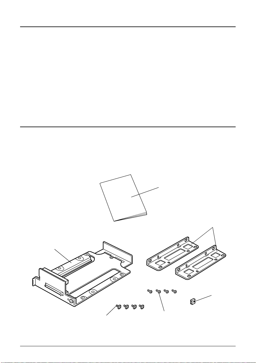
Unpacking
The following items are packed together with this product. If any items
are damaged or missing, please contact your dealer for assitance.
User‘s manual
frame unit
upper HDD mounting screw
(cup screw)
bracket
jumper socket
lower HDD mounting screw
1
Page 6
Installation
CAUTION
❏ Before installation, please ground yourself to avoid generating
static electricity by touching a grounded metal surface. Not
allowing static electricity to discharge can cause damage to this
product.
❏ Do not touch the connector with your bare hand. Dirt may cause
multifunction.
Installing the HDD
Install the HDD to the 2HDD bracket u sing the follo wing procedure.
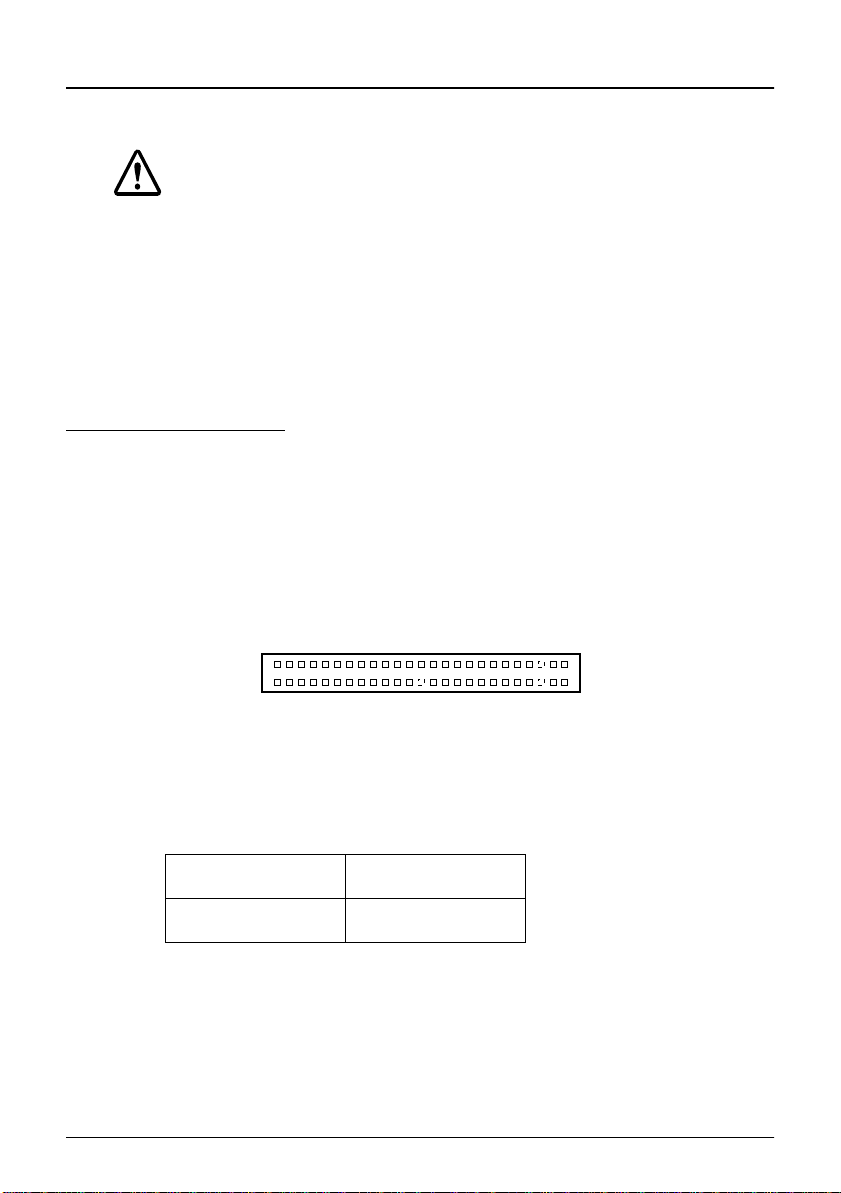
1. In the case of an HDD that is used as the 2nd (slave) drive, set the
jumper as shown below before installing it in the frame unit.
HDD Jumper Settings
2
43
44
HDD Connector
Maker Jumper Setting
Toshiba Short C and D
1
CA
DB
2
Page 7

To set the jumpers, mount the supplied jumper socket to the HDD.
2. Slide the HDD as shown in the figure below and connect the
connector on the HDD to the lower connec tor on t he fra me unit . At
this time, you can mount either the first HDD(Master) or the second
HDD (Slave).
curcuit board
lower connector
CAUTION
When connecting the HDD connector to the connector on the frame
unit, support the curcuit board not to give a stress to the curcuit
board and make sure that the HDD is connected properly.
3
Page 8

3. With the bracket at the side of the frame unit, fast en the lower HDD
to the frame unit with the lower HDD mounting screws from the
rear of the frame unit (two places.) Fasten the other bracket in the
same way.
CAUTION
❏ Tighten the screws used to mount the HDD with a tightening
torque of 29.4 cN•m {3 kgF• cm}. If a force greater than this is
exerted in tightening, it could cause the HDD to malfunction.
❏ Do not use other than the supplied screws. If you use, the HDD
and the IM-300 can be damaged.
❏ Both the rear holes and the side holes on the HDD may differ
depending on the HDD. Tighten the mounting screws at the
appropriate places.
4. Connect the other HDD to the upper connector on the frame unit.
4
Page 9

5. Fasten the HDD at both sides with the upper HDD mounting
screws (four places.)
CAUTION
The upper HDD will be in an unstable condition until it is fastened
with screws. If it is pushed from above, it is possible that the
connector pins could be bent, so please exercise caution when
handling it.
Installation in the IM-300
Install the 2HDD bracket in the IM-300 using the following procedure.
CAUTION
During installation, please be careful not to subject the drive to
impacts or vibration. Since the hard disk is a precision device, it
could be damaged by impacts or vibrations.
1. Turn off the power of the IM-300 and peripheral devices.
5
Page 10

CAUTION
Before installing the 2HDD bracket, be sure to turn off the power of
the IM-300, peripheral devices, and the HDD. With the power on,
the IM-300, peripheral devices and the HDD may be damaged.
2. Open the IM-300's front cover. If it is locked, release the lock using
the front key.
3. Open the HDD cover.
HDD cover
6
Page 11

4. Slide the 2HDD bracket in which two HDDs are mounted into the
grooves of the IM-300 base unit and install it.
If an HDD is already mounted in the IM-300, take out the screws
fastened the HDD bracket to the IM-300, and pull out the 2HDD
bracket to remove the mounted HDD; then mount the 2HDD
bracket again.
5. Fasten the 2HDD bracket in place with screws, then close the HDD
cover.
6. Close the front cover and lock it with the front key.
7
Page 12

Precautions When Using
❏ Set the HDD unit that is to be the first drive (Master) and the
second drive (Slave) using the jumpers on the HDD. It does not
matter which HDD, the first drive or the second drive, is conn ected
to which connector. Also, if both drives are set on the same setting
(Master and Master, or Slave and Slave), they will not work, so
please exercise caution.
❏ The 2HDD bracket can be installed with only one HDD. At this
time, be sure to use the HDD with the jumper removed (open).
❏ If only one HDD unit is used with the 2HDD bracket, be sure to
connect it to the lower connector. Do not connect a single HDD to
the upper connector.
❏ In the IM-300 system, there is no HDD mirroring function. If you
save the data on the first HDD onto the second HDD, use the
commercial backup utilities.
❏ If the second HDD is not recognized, check the Standard CMOS
Setup in the BIOS Setup utility to see if the Primary Slave TYPE
setting is on AUTO (if it is not set on NONE).
❏ The HDD DMA is not supported in the IM-300
8
Page 13

List of Specifications
HDD which can be Installed
Thickness : 2.5 inch, 12.7 mm thick or less
Interface : ATA (IDE/E-IDE) 44-pi n
Power Supply +5V/2A of lower for the 2 drives
Environmental Specifications
During Operation
Temperature : 5~35°C
Humidity (RH) :30~80% (without condensation)
During Storage
Temperature :-10~50°C
Humidity (RH) :30~90% (without condensation)
9
Page 14

Connector Specifications
The connector pin assignment for connection to the HDD is as shown
below.
HDD Connection Connector CN1,3
Pin NoSignal
Name
I/O Explanation
Pin NoSignal
Name
I/O Explanation
1 RESET# O Reset Signal 2 GND - Groun d
3 DD7 I/O
4 DD8 I/O
5 DD6 I/O 6 DD9 I/O
7 DD5 I/O 8 DD10 I/O
9 DD4 I/O 10 DD11 I/O
11 DD3 I/O 12 DD12 I/O
Data Signal
(lower order 8 bits)
Data Signal
(higher order
8 bits)
13 DD2 I/O 14 DD13 I/O
15 DD1 I/O 16 DD14 I/O
17 DD0 I/O 18 DD15 I/O
19 GND - Ground 20 KEY 21 DMARQ I
DMA Request Signal*1
22 GND - Ground
Wrong Insert ion Pre ven tio n pin
23 DIOW# O Write Strobe Signal 24 GND - Ground
25 DIOR# O Read Strobe Signal 26 GND - Ground
27 IORDY I I/O Ready Sign al 28 CSEL O
29
DMACK#
DMA Acknowledge Signal
O
30 GND - Ground
31 INTRQ I Interrupt Signal 32 IOCS16# O
33 DA1 O
35 DA0 O
Address Decode Signal 1
Address Decode Signal
34 PDIA G# I/O
36 DA2 O
Master/Slave Select Signal *1
16-bit Transfer Mode Signal
Master/Slave Intercommunication Signal
Address Decode Signal 2
37 CS0# O C hip Select Signal 38 CS1# O Chip Select Signal
39 DASP# I Drive Access Signal 40 GND - Ground
41 +5V -
5 V Power Supply (Logic)
42 +5V -
55 V Power Supply (Motor)
43 GND - Ground 44 Reserved - Reserved
10
Page 15

• # in the signal name indicates an active low signal.
• The signal direction is as viewed from the outside of the connector.
*1 :The CSEL signal is not used in the IM-300.
Connector : LY30-44S-DT7-1-10 (made by Japan Airlines
Electronics)
1
2
HDD Connection Connector
KEY
43
44
11
Page 16

5
Page 17

Printed in Japan
1998.07
6
 Loading...