

Page 1

SOLID DISK
OI-M04
User’s Manual
400920201
1
Page 2

Notice
1. All rights reserved. Reproduction of any part of thi s manual in any
form whatsoever without EPSON’s express written permission is
forbidden.
2. The contents of this manual are subject to change without
notice.Please contact us for the latest information.
3. All efforts have been made to ensure the acc uracy o f the co ntents of
this manual. However, should any errors be detected, EPSON
would greatly appreac iate being informed of them.
4. The above notwithstanding, EPSON can assume no responsibility
for any errors in this manual or their consequences.
5. Neither Seiko Epson Corporation nor its affiliates shall be liable to
the purchaser of this product or third parties for damages, losses,
costs, or expenses incurred by the purchases or third parties as a
result of: accident, misuse, or abuse of this product or
unauthorized modifications, repairs, or alterations to this product,
or (excluding the U.S.) failure to strictly comply with Seiko Epson
Corporation’s operating and maintenance instructions.
6. Seiko Epson Corporation shall not be liable against any damages or
problems arising from the use of any options or any consumable
products other than those designated as Original EPSON Products
or EPSON Approved Products by Seiko Epson Corporation.
2
Page 3

Contents
1. Overview . . . . . . . . . . . . . . . . . . . . . . . . . . . . . . . . . . . . . . . . . . . . . . . . . . . . . 1
2. Unpacking . . . . . . . . . . . . . . . . . . . . . . . . . . . . . . . . . . . . . . . . . . . . . . . . . . . . 2
3. Types of Usage . . . . . . . . . . . . . . . . . . . . . . . . . . . . . . . . . . . . . . . . . . . . . . . . 3
4. Flash ROM Mounting and DIP Switch/Jumpers Setting. . . . . . . . . . . . . 4
5. ROM board Mounting and Jumper Setting . . . . . . . . . . . . . . . . . . . . . . . . 8
6. Installation Procedure . . . . . . . . . . . . . . . . . . . . . . . . . . . . . . . . . . . . . . . . . 11
7. Precautions When Using . . . . . . . . . . . . . . . . . . . . . . . . . . . . . . . . . . . . . . . 16
8. Software . . . . . . . . . . . . . . . . . . . . . . . . . . . . . . . . . . . . . . . . . . . . . . . . . . . . . 18
9. Specification. . . . . . . . . . . . . . . . . . . . . . . . . . . . . . . . . . . . . . . . . . . . . . . . . . 22
Appendix1. Example of Display . . . . . . . . . . . . . . . . . . . . . . . . . . . . . . . . . . 23
(C) SEIKO EPSON CORPORATION 1998
3
Page 4

About the Symbols
Following symbols are used in this manual.
CAUTION
Failure to observe a CAUTION may result in personal injury, or in
damage to equipment or other property.
Note
Notes have important information and useful tips on the operation
of your printer.
4
Page 5

DECLARATION of CONFORMITY
Product Name : ROM Board
Type Name : M144A
The ROM Board conforms to the following Directives and Norms
Directive 89/336/EEC
EN 55022(1987/1994 2nd/1995) Class A
EN 50082-1(1992)
IEC 801-2 (1991)
IEC 801-3 (1984)
IEC 801-4 (1991)
Warning
This is a Class A product. In a domestic enviro nment this product may
cause radio interference in which case the user may be re quir ed to tak e
adequate measures.
1
Page 6

FCC CLASS A
FCC COMPLIANCE STATEMENT FOR AMERICAN USERS
This equipment has been tested and found to compl y with the l imits for
a Class A digital device, pursuant to Part 15 of the FCC Rules. These
limits are designed to provide reasonable protection against harmful
interference when the equipment is operated in a commercial
environment.
This equipment generates, uses, and can radiate radio frequency
energy and, if not installed and used in accor dance with the inst ructio n
manual, may cause harmful interference to radio communications.
Operation of this equipment in a residential area is likely to cause
harmful interference, in which case the user will be required to correct
the interference at his own expense.
WARNING
The connection of a non-shielded interface cable to this product will
invalidate the FCC Verification of this device and may cause
interference levels which exceed the limits established by the FCC for
this equipment.
You are cautioned that changes or modifications not expressly
approved by the party responsible for compliance could void your
authority to operate the equipment.
FOR CANADIAN USERS
This Class A digital apparatus complies with Canadian ICES-003.
Cet appareil numérique de la classe A est comforme à la norme NMB003 du Canada.
2
Page 7

This manual explains how to set up the Solid Disk OI-M04.
Overview
The Solid Disk OI-M04 is an option for the IM-505, the IM-300, and the
IM-515.
The Solid Disk provides ROM disk functions t hrough software, a nd the
following functions can be available.
❏ Data can be stored on the Solid Disk the same as on a hard disk
drive (Max1.8MB).
❏ The system can be booted from the Solid Disk.
The Solid Disk has the following two types.Those types are used
depending on your IM.
* OI-M04-011
• For IM-505/IM-300
• ROMs without ROM board
* OI-M04-021
• For IM-515
• ROMs with ROM board
Following programs are supplied on a 3.5” floppy disk.
❏ Install Program (DLFINST.BAT )
❏ Device Driver (DLFFS.EXE)
❏ BIOS Expansion ROM Image
(DLFFS.IMG, DLFFS1ST.IMG, UNINST.IMG)
1
Page 8

❏ Installation Test Program (TESTOEM.EX E)
❏ Formatting Utility (DLFMT.EXE)
❏ ROM Image writing Utility (WUSRROM.COM)
❏ Configuration File
(CONFIG.SYS,AUTOEXEC.BAT))
The Solid Disk can be available on the following
Operating System.
❏ MS-DOS Ver.5.0 or later
❏ Microsoft Windows 3.1
❏ Microsoft Windows 95
The Solid Disk will not work with the Windows NT.
2
Page 9
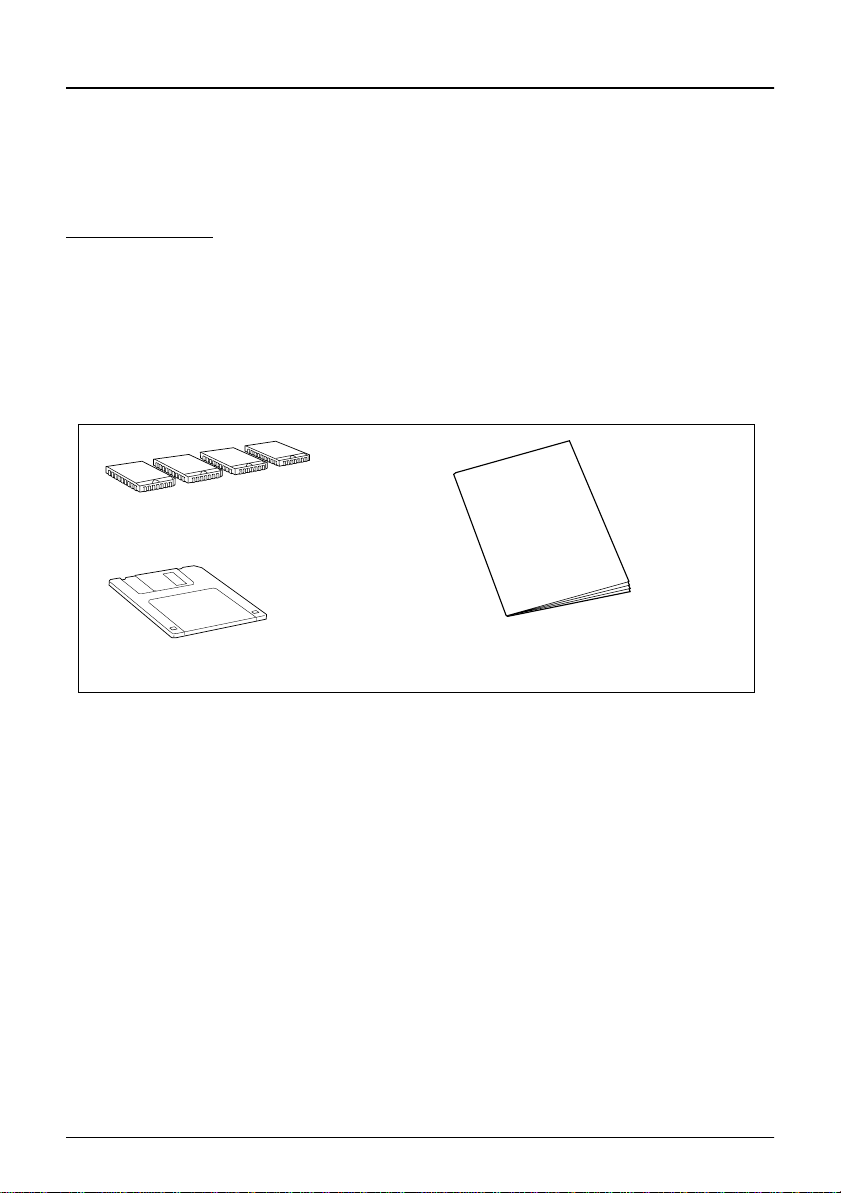
Unpacking
The following items are in the box.
OI-M04-011
• Flash ROMs x 4
• 3.5” Floppy Disk x 1
•User’s Manual
Flash ROMs
floppy disk
user‘s manual
3
Page 10
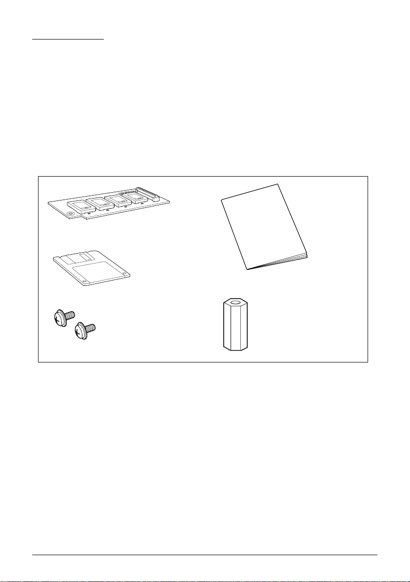
OI-M04-021
• ROM board mounted four Flash ROMs x 1
• Cup head screw x 2
•Spacer x 1
• 3.5” Floppy Disk x 1
•User’s Manual
ROM board mounted
four Flash ROMs
user‘s manual
floppy disk
cup screw
spacer
Make sure that you have all the items and that none has been damaged.
If you find any missing or damaged items, please contact your dealer.
4
Page 11

Solid Disk Usage
The solid disk includes the following three usages. Method of installing
differs for each.
If you want to change the usage t ype of the soli d disk, execute the ROM
image deleting utility, and then execute Installation Program
(DLFINST.BAT.)
(a) C Drive Emulation/Expansion ROM mode (BIOS Extension)
The Solid Disk is used as the first hard disk. Booting is executed
from the system installed in the Solid Disk. The name of the drive is
always “C Drive.” If there is a hard disk, drive names beginning
with “D Drive” and those subsequent may be assigned to the hard
disk. If applications in the Solid Disk always reference the same
drive, you have the advantage of being able to fix the drive name.
(b) Bo otable HDD Emulation /Exp ansion ROM mode (BIOS Extension)
Used as an additional hard disk. If a system is installed in the Solid
Disk, you can boot from that system. If however the hard disk
exists as C Drive, you cannot boot from the Solid Disk. The next
drive name following that of the hard disk is assigned to this
function. If for example “C Drive” is assigned to the hard disk, the
name would be “D Drive.” If there is no hard disk, “C Drive” is
assigned. The Solid Disk offers the advantage of the drive
remaining assigned even if the hard disk is replaced, but it cannot
be easily deleted.
(c) Non-bootable HDD Emulation /Normal ROM mode (Used by de vice
driver)
Used for data storage. Drive is assigned by the device driver
contained in CONFIG.SYS when the system is booted from the
hard disk or floppy disk. Drive name depends on system
configuration. If the drive is not needed, it can be easily deleted by
deleting the driver.
5
Page 12

Flash ROM Mounting and DIP Switches/
Jumpers Setting
Mount flash ROMs using the following procedure. Please refer to the
IM-300/505’s user’s guide. When you mount the ROM board into the
IM-515, omit this section and go to “5. ROM Board Mounting and
Jumpers Setting.”
CAUTION
❏ Before you mount the flash ROMs, turn off the power of the IM-
505/IM-300 and unplug the power cord from the ou tlet.
With the power on, the IM-505/IM-300 may be damaged.
❏ To aviod generating static electricty and damaging the ROM,
ground yourself by touching a grounded metal surface before you
touch the flash R OM .
Not allowing static electricity to dischage, can cause damage.
IM-505
1. Remove the transportation screw at the base of the IM-505 when it
is not remov ed.
2. Use the key to unlock the lock at the front of the cover set and open it .
3. Move the tab on the plate lock of the rear to UNLOCK and then
pull the IM module out.
4. Mount flash ROMs in the flash ROM sockets sequentially from
socket #1. Ensure that each ROM is mounted in the cor rect direction
as shown illustrations on page 6. And be sure to push down the
user ROM onto the socket. Mount all four flash ROMs.
5. Set the DIP switch to normal ROM mode. See page 8-10 for the
place and setting of the jumpers.
6. Replace the IM module to the housing.
6
Page 13

IM-300
1. Remove the left side cover.
2. Remove two screws which fix a side panel and remove the side
panel.
3. Mount flash ROMs in the flash ROM sockets sequentially from
socket #1. Ensure that each ROM is mounted in the cor rect direction
as shown illustrations on page 6. And be sure to push down the
user ROM onto the socket. Mount all four flash ROMs.
4. Set the jumper to normal ROM mod e. See p age 8-10 for t he posi tion
and the setting of the jumper.
5. Replace the side panel and side cover.
7
Page 14

IM-505
External I/O board
Flash ROM Sockets Dip Switches
Flash ROM direction
JumperJ9
Flash ROM Sockets
Flash ROM direction
SW1
JumperJ21
SW6
IM-300
8
Page 15

DIP Switches/Jumpers Setting
A following table shows the setting of the Flash ROM Control DIP
Switches/Jumpers setting. Refer to”6 Installation Procedure” for
details (page 14 - 18.)
IM-505
DIP switches on the External I/O board:
SW1-1 SW1-2 SW1-3 SW1-5 Function
ON ON ON ON Normal ROM Mode
ON ON OFF ON Expansion ROM Mode
(Start Address: C8000h)
ON OFF ON ON Expansion ROM Mode
(Start Address: D0000h)
ON OFF OFF ON Expansion ROM Mode
(Start Address: D8000h)
OFF - - ON Reserved
- - - OFF Flash ROM Not Used
CAUTION
Make sure jumper J9 on the extension I/O board is set to 2-3. If
jumper J9 on the extension I/O board is not set to 2-3, the solid disk
cannot be used.
9
Page 16

IM-300
Jumper J21:
1-2
(SW1)
3-4
(SW2)
5-6
(SW3)
9-10
(SW5)
11-12
(SW6)
Function
ON ON ON ON ON Normal ROM Mode
ON ON OFF ON ON
ON OFF ON ON ON
ON OFF OFF ON ON
Expansion ROM Mode
(Start Address: C8000h)
Expansion ROM Mode
(Start Address: D0000h)
Expansion ROM Mode
(Start Address: D8000h)
OFF - - ON ON Reserved
----ONFlash ROM Not Used
Note
Extension ROM mode starting address C8000h cannot be set for the IM-300
because the Video BIOS exists there.
10
Page 17

ROM Board Mounting and Jumpers Setting
When you mount the ROM board in the IM-515 using the following
procedure.
CAUTION
❏ Before you mount the ROM board, turn off the po wer of the IM-515
and unplug the power cord from the outlet.
With the power on, the IM-515 may be damaged.
❏ To avoid generating static electricity and damaging the ROM,
ground yourself by touching a grounded metal surface before you
touch the ROM board.
Not allowing static electricity to discharge, can cause damage.
1. Make sure the jumpers J2/J3 on the ROM board are set to normal
ROM mode.
Jumper J2/J3:
J2 J3 Function
2-3 2-3
2-3 1-2
1-2 2-3
1-2 1-2
Normal ROM Mode
(Default setting)
Expansion ROM Mode
(Start Address: C8000h )
Expansion ROM Mode
(Start Address: D0000h)
Expansion ROM Mode
(Start Address: D8000h)
11
Page 18

2. Remove the transportion screw from the base of the IM-515 when
it is not removed.
3. Use the key to unlock the lock at the front of the cover set and open
it.
4. Move the tab on the plate lock to UNLOCK
and then pull the IM module out.
5. Remove the two screws fixing the main board to the IM module
and pull out the main board.
main board
6. Push down the connector on the ROM board (CN1) onto the
connector on the main board (CN6).
ROM board
CN1
CN6
main board
12
Page 19

7. Put the spacer into both holes on the ROM board and the main
board, and tighten with the cup head screws from both sides of the
spacer to fix the ROM board to the main board as shown below.
cup screw
ROM board
main board
spacer
8. Reattach the main board to the IM module with the two screws and
replace it in the housing. Be sure to push the IM module into the
housing until it clicks into place; then the tab on the plate lock
moves to LOCK.
9. Close and lock the front panel.
13
Page 20

Installation Procedure
C Drive Emulation/Bootable HDD Emulation
(BIOS Extension)
If using the S olid Disk for (a) C Drive Emulation or (b) Bootable HDD
Emulation, install according to the following procedure.
1. Copy an MS-DOS system on a floppy disk. And copy SYS.COM if
you plan to use the Solid Disk as a boot drive.
2. Copy all the files from the floppy disk that comes with the Solid
Disk onto the route directry of thefloppy disk you are preparing.
3. If the IM-300/IM-505/IM-515’s power is on, turn the power off.
4. If an expansion board which uses the memory address D0000h
exists, remove it, or reset its memory address not to use D0000h. If
you remove the expansion board, reattach it after you install the
solid disk.
5. Make sure the following DIP switch or jumper for flash ROM
control to normal ROM mode.
(For position and setting, see page 8-10.)
IM-505: DIP switch on extension I/O port
IM-300: Jumper J21
IM-515: Jumper J2/J3
6. If using an IM-505, make sure jumper J9 on the extension I/O board
is set to 2-3. If jumper J9 on the extension I/O board is not set to 2-3,
the solid disk cannot be used.
7. If using an IM-300, make sure 11-12 (SW6) of jumper J21 is set to
“ON” (short). If 11-12 (SW6) of jumper J21 is not set to “ON,” the
Solid Disk cannot be used.
14
Page 21

8. Set the disk prepared i n step 2 in the flop py d isk d ri ve and tur n t he
IM-300/IM-505/IM515’s power on. Write down the drive name of
the Solid Disk which is then displayed. (Refer to” Appendix1.
Example of display” (page 25) )
9. Input the following command and execute the Installation Test
Program:
TESTOEM /F
For details concerning the TESTOEM command, see page 18. If an
error occurs while the Installation Test Program is running, check
the DIP switch / jumper setting, and make sure the flash ROM i s
inserted properly.
10. Boot the installation pr ogram by inputting the fol lowing command.
Make sure the Input paramet ers dif fer in accordance with the usage
of the solid disk.
For C Drive Emulation:
DLFINST /1
For bootable HDD emulation:
DLFINST /h
11. When the install progr am is fi nished r unni ng, format t he soli d disk
by inputting the following command:
DLFMT d:
(Input the drive name confirmed in step 8 for d)
The followi ng warning mes sages are displayed:
Warning! You lose all data on xxxK Flash card in drive d: Format
the card?
Press Y key and then Enter key to start formatting.
For details concerning the DLFMT command, see page 21.
12. To enable booting from the solid disk, transmit the system file by
inputting the the follow command:
SYS d:
13. Turn the IM-300/IM-505/IM-515’s power off.
15
Page 22

14. Switch the DIP switch or jumper for flash ROM contro l to extension
ROM mode.For details concerning the DIP Switches/Jumpers
settings, see page 8-10.
Select a starting address which does not duplicate addresses used
by other software. For BIOS extension, the Solid Disk uses 16KB of
memory space.
If using a memory manager such as EMM386.EXE, set the memory
space used by the solid disk so it will not be used by the solid disk.
The memory space used by the solid disk is 16KB from the starting
address set by the DIP switch. If, for example, the solid disk uses
the 16KB from D0000h to D3FFFh, add /X=D000-D3FF to the
EMM386.EXE setting of CONFIG.SYS.
DEVICE = C:\DOS\EMM386.EXE RAM /X=D000-D3FF
If using a memory manager other than EMM386.EXE, set in
accordance with the specifications of each memory manager.
Note
Extension ROM mode starting address C8000h cann ot be set for the
IM-300 because the Video BIOS exists there.
15. Remove the floppy disk, re-boot, and see if the system operates
normally.
Non-Bootable HDD Emulation (Used by device driver)
If using the Solid Disk for (c) Non-bootable HDD Emulation, install
according to the followi ng procedure.
1. Copy an MS-DOS system on a floppy disk.
2. Copy all the files from the floppy disk that comes with the Solid
Disk onto the floppy disk you are preparing.
3. If the IM-300/IM-505/IM-515’s power is on, turn the power off.
4. If an expansion board which uses the memory address D0000h
exists, the solid disk cannot be used as a non-bootable HDD
emulation mode. Be sure to reset the memory address of the
expansion board not to use D0000h.
16
Page 23

5. Make sure the following DIP switch or jumper for flash ROM
control to normal ROM mode.
(For position and setting, see page 8-10.)
IM-505: DIP switch on extension I/O port
IM-300: Jumper J21
IM-515: Jumper J2/J3
6. If using an IM-505, make sure jumper J9 on the extension I/O board
is set to 2-3. If jumper J9 on the extension I/O board is not set to 2-3,
the solid disk cannot be used.
7. If using an IM-300, make sure 11-12 (SW6) of jumper J21 is set to
“ON” (short). If 11-12 (SW6) of jumper J21 is not set to “ON,” the
Solid Disk cannot be used.
8. Set the disk prepared i n step 2 in the floppy disk d rive and tur n t he
IM-300/IM-505/IM515’s power on. Write down the memory
address and drive name of the Solid Disk which are then d isplayed.
(Refer to “Appendix1 Example of display” (page 25). )
9. Input the following command and execute the Installation Test
Program:
TESTOEM /F
For details concerning the TESTOEM command, see page 20. If an
error occurs while the Installation Test Program is running, check
the DIP switch / jumper setting, and make sure the flash ROM i s
inserted properly.
10. Create a directory on the HDD for copying the device driver.
If for example you wanted to create a directory called “SOLID” for
C Drive, you would input the following:
MD C:\SOLID
11. The installation program is booted as follows:
DLFINST /d d1:\directory
(The directory name created in st ep 1 0 pl us t he dr ive name i s in put
for “d1:\directory”.)
In this case, you would input as follows:
DLFINST /d C:\SOLID
17
Page 24

12. When the install progr am i s fi nished r unni ng, format the solid disk
by inputting the following command:
DLFMT d2:
(Input the drive name confirmed in step 8 for d2)
For details concerning the DLFMT command, see page 20.
13. Install the device driver. To do so, enter the device driver of the
solid disk in the installed CONFIG.SYS file in step 10 using Editor,
etc.
DEVICE= d1:\directo ry \DLFFS.EXE
An sample CONFIG.SYS is given below.
DEVICE=C:\SOLID\DLFFS.EXE
If using a memory manager such as EMM386.EXE, set the memory
space used by the solid disk so it will not be used by memory
manager. For memory space used by the solid disk, input the
setting displayed for device driver when the MS-DOS system is
booted. If for example the solid disk’s device driver uses the 16KB
from D0000h - D3FFFh, add /X=D000-D3FF to the EMM386.EXE
setting of CONFIG.SYS.
DEVICE=C:\DOS\EMM386.EXE RAM /X=D000-D3FF
If using a memory manager other than EMM386.EXE, set in
accordance with the specifications of each memory manager.
14. Turn off the IM-300/IM-505/IM-515.
15. Remove the floppy disk, re-boot, and see if the system operates
normally.
18
Page 25

Precautions When Using
Keep the following points in mind when using the Solid Disk.
❏ The Solid Disk will not work with Windows NT.
❏ Do not install a device driver if using the solid disk with a BIOS
extension.
❏ If using Windows 95, MS-DOS c ompatibility mode is used for all
file system operations, and 32-bit access is therefore impossible.
When the Solid Disk is installed through the device driver, MSDOS compatibility mode is also used for the file system of the
internal hard disk drive.
❏ If using an IM-505, the solid disk may not be recognized when
executing software reset (reset by simultaneously pressing the
CTRL, ALT and DEL keys). If reset must be ex ecuted whil e using
the Solid Disk, be sure to execute a hardware reset by means of the
reset switch.
❏ Do not execute the foll owing o perations, or all the d ata on the Soli d
Disk will b e lost.
1. Write the BIOS expansion image to the ROM.
2. Set the DIP switch to the normal ROM mode.
3. Install the device driver.
At this time, the drive configurations will be as follows:
C Drive: Installed HDD
D Drive: Solid Disk installed as BIOS expansion
E Drive: Solid Disk installed through the de vice driver
19
Page 26

4. When you access the D or the E in this situation, the data on the
Solid Disk will be lost.
If you execute the above operation, you must execute the
installation again.
❏ When the BIOS version of the IM-515 is Ver.1.02 or below, the solid
disk cannot be used as “C Drive Emulation/Bootable HDD
Emulation” (see page 11) in Windows95.In th is case, rewrite the
current BIOS with BIOS Ver.1.03 or above to use the OI-M04 in
Windows95.
❏ Before using the Solid Disk, be sure to format the Solid Disk using
the format utility (DLFMT.EXE) attached to this product.
❏ As for the IM-515, Form at command of the MS-DOS c annot be used
in the MS-DOS window of the Windows 95.
Software
Installation Test Program
Installation test program (TESTOEM.EXE) checks that the flash ROMs
are correctly mounted in the flash ROM sockets and can be used as the
Solid Disk.
CAUTION
When this utility is executed, all the data on the Solid Disk will be
lost. Before you execute this u tility, save all the important data to
the hard disk drive or so.
Format:
TESTOEM /F
Options:
/F Execute the read/write check onto the Solid Disk.
20
Page 27

Note
The Installation test program has a few other options that /F. But
they are meaningless for the IM-505/IM-300/IM-515.
Explanation:
The Installation test program is a utility that checks whether the Solid
Disk works properly or not.
This utility writes and reads each byte in the Solid Disk. When the test
is complete, the following message is diapla yed if the Read/Write test
was successful all bytes:
All tests passed.
If an error is detected during the test, a problem exists with the DIP
switch/jumpers settings or with mounting of the ROMs. Check and
take appropriate measures.
Formatting Utility
The formatting utility (DLFMT.EXE) is a utility to format the Solid Disk
for use with MS-DOS.
CAUTION
When this utility is executed, all the data on the Solid Disk will be lost.
Before you execute this utility, save all the i mportant data to the hard
disk drive or so.
Note
❏ The Solid Disk must be installed before running this command.
❏ Before using the Solid Disk, be sure to format it by usin g this
command.
Format:
DLFMT d: [/C] [/V]
Options in the brackets can be omitted.
Options:
d: Specify the Solid Disk drive name to be formatted.
21
Page 28

/C Format the Solid Disk without displaying a warning message.
/V After formatting, prompt user to enter the volume label.
Explanation:
This utitity formats the Solid Disk. Be sure to specify the driv e name to
be formatted.
For example, if the Solid Disk is to become drive D, enter as follows:
DLFMT D:
If you do not know the drive name of the Solid Dsik, it is being
displayed at the system execution. Please check it.
If the /C option is not specified, the following warning messages are
displayed:
Warning! You lose all data on xxxK Flash card in drive d: Format the
card?
Press Y key to start formatting. Press any other key to quit without
formatting.
If /C is specified, formatting starts without displaying the warning
messages above.
The following message is displayed when formatting is complete:
Format complete.
When /V is specified, inputting a volume lable follows.
ROM Image Deleting Utility
The ROM image deleting utility (WUSRROM.COM) deletes the ROM
image on the Flash ROM.
22
Page 29

CAUTION
When this utility is executed, all the data on the Solid Disk will be
lost. Before you execute this u tility, save all the important data to
the hard disk drive or so.
Format:
WUSRROM -S1 UNINST.IMG
Explanation:
This utility deletes the ROM image written onto the Flash RO M at the
installation
Installation Program.
Installation Program (DLFINST.BAT) is a batch program that sets the
environments in accordance with the usage of the solid disk.
Format:
For C drive emulation:
DLFINST /1
For Bootable HDD emulation:
DLFINST /h
For Non-bootable HDD emulation:
DLFINST /d d1: \directory
d1: \directory indicates the directory which solid disk device drivers
are copied to.
Explanation:
This batch program sets the environments of solid disk. Use this
program when you first install the so lid disk o r you want to change t he
usage of the solid disk.
23
Page 30

Specifications
Operation environment
Temperature: 5 to 35ºC
Humidity: 30 to 85% (without condensation)
Storage environment
Temperature: -10 to 50ºC
Humidity: 30 to 90% (without condensation)
Flash ROM
Name 4BM29F040C-90PD
Capacity Approximately 1.8MB (Sum of four ROMs)
Life span (Erase/Write Cycle)
Minimum:100,000 times
Standard:1,000,000 times
ROM board dimension
98.5 mm(3.88 in.) x 37 mm(1.46 in.)
24
Page 31

Appendix1. Example of Display
CardTrick v.3.00.61
Copyright(c)1993-1996,Datalight Ind.
Datalight Patent Pending
Resident Flash (RFA) OEM Layer
Window Address=D000h
Window Size=16
Drive(s)D
Write down the underlined part as a drive name of the solid disk.
25
Page 32

5
Page 33

Printed in Japan
6
 Loading...