

Page 1
EZ-Tear Thermal Printer
Owner's Manual
First Edition: July 2004
Last Revision: July, 2005
Document #102136
Page 2

EZ-Tear Thermal Printer
Owner’s Manual
Legal Notices
Disclaimer
Information in this document is subject to change without notice. Consult your Nanoptix Inc. sales
representative for information that is applicable and current. Nanoptix Inc. reserves the right to
improve products as new technology, components, software, and firmware become available.
No part of this document may be reproduced or transmitted in any form or by any means,
electronic or mechanical, for any purpose without the express written permission of Nanoptix Inc.
Copyright
Copyright 2004 by Nanoptix Inc.
Dieppe, New Brunswick Canada
All rights reserved
Printed in Canada
Confidential, Unpublished
Property of Nanoptix Inc.
Trademarks
Epson is registered trademark of Epson Corporation.
Windows is registered trademark of Microsoft Corporation.
Nanoptix is a trademark. Other trademarks and registered trademarks are the property of their
respective holders.
Federal Communications Commission (FCC)
Radio Frequency Interference Statement
Warning
Changes or modifications to this unit not expressly approved by the party responsible for
compliance could void the user’s authority to operate the equipment.
Note
This equipment has been tested and found to comply with the limits for a Class B digital device,
pursuant to Part 15 of the FCC Rules. These limits are designed to provide reasonable protection
against harmful interference when the equipment is operated in a commercial environment. This
equipment generates, uses, and can radiate radio frequency energy and, if not installed and used
in accordance with the instruction manual, may cause harmful interference to radio
communications. Operation of this equipment in a residential area is likely to cause harmful
interference in which case the user will be required to correct the interference at his own
expense.
Information to the User
This equipment must be installed and used in strict accordance with the manufacturer's
instructions. However, there is no guarantee that interference to radio communications will not
occur in a particular commercial installation. If this equipment does cause interference, which can
be determined by turning the equipment off and on, the user is encouraged to contact Nanoptix
Inc. immediately.
102136
July, 2005
ii
Page 3

EZ-Tear Thermal Printer
Owner’s Manual
Nanoptix Inc. is not responsible for any radio or television interference caused by unauthorized
modification of this equipment or the substitution or attachment of connecting cables and
equipment other than those specified by Nanoptix Inc. The correction of interferences caused by
such unauthorized modification, substitution or attachment will be the responsibility of the user.
In order to ensure compliance with the Product Safety, ICES, FCC and CE marking requirements,
you must use the power supply, power cord, and interface cable which were shipped with this
product or which meet the following parameters:
Power Supply
UL Listed power supply with standard 60Hz-50Hz, 100-240VAC input and 24VDC output
equipped with AC line filtering, over-current and short-circuit protection.
Use of this product with a power supply other than the Nanoptix Inc. power supply will require you
to test the power supply and Nanoptix Inc. printer for FCC and CE mark certification.
Communication Interface Cable
An approved Nanoptix interface cable must be used with this product. Using a cable other than
Nanoptix approved product will require that you test the cable with the Nanoptix Inc. printer and
your system for FCC and CE mark certification.
Power Cord
A UL listed, detachable power cord must be used. A power cord with Type SVT marking must be
used. For applications outside the North America, power cords that meet the particular country’s
certification and application requirements should be used.
Use of a power cord other than described here may result in a violation of safety certifications
that is in force in the country of use.
Industry Canada (IC)
Radio Frequency Interference Statement
This Class A digital apparatus meets all requirements of the Canadian Interference-Causing
Equipment Regulations.
Cet appareil numérique de la classe A respecte toutes les exigences du Règlement sur le
matériel brouilleur du Canada.
102136
July, 2005
iii
Page 4

EZ-Tear Thermal Printer
Owner’s Manual
Table of Contents
1. About the Printer..................................................................... 1
1.1 Description of Printer ...................................................................................1
1.2 Models Available...........................................................................................2
Connector Orientation.............................................................................................................. 2
1.3 General specifications..................................................................................3
1.4 Installation.....................................................................................................4
Mounting your printer............................................................................................................... 4
1.5 Printer Controls.............................................................................................4
To reset Printer........................................................................................................................ 4
Paper Feed Button................................................................................................................... 5
1.6 Changing Paper ............................................................................................6
1.7 Testing the Printer........................................................................................8
1.8 Troubleshooting the Printer .........................................................................9
Printer LED .............................................................................................................................. 9
Printing Problems .................................................................................................................... 9
Printer Does Not Work...........................................................................................................10
2. Media and Supplies Guide.................................................... 10
2.1 Thermal Paper Specifications....................................................................10
2.2 Ordering Thermal Paper.............................................................................10
2.3 Ordering Miscellaneous Supplies .............................................................11
Power Supply and Power Cord.............................................................................................. 11
Ordering Communication Cables........................................................................................... 11
Communication Cables Pin-Out ............................................................................................12
3. Communicating with the Printer.......................................... 13
APPENDIX A: Mechanical Drawings............................................. 14
102136
July, 2005
iv
Page 5

EZ-Tear Thermal Printer
Owner’s Manual
Figures
FIGURE 1: NANOPTIX EZ-TEAR PRINTER ............................................................................................1
FIGURE 2: NANOPTIX EZ-TEAR CONNECTION...................................................................................... 2
FIGURE 3: RESETTING PRINTER.......................................................................................................... 4
FIGURE 4: PAPER FEED BUTTON........................................................................................................ 5
FIGURE 5: LOADING PAPER................................................................................................................ 6
FIGURE 6: TEST TICKET ..................................................................................................................... 8
102136
July, 2005
v
Page 6

EZ-Tear Thermal Printer
Owner’s Manual
Tables
TABLE 1: SPECIFICATION ................................................................................................................... 3
TABLE 2: TROUBLESHOOTING WITH THE STATUS LED......................................................................... 9
TABLE 3: TROUBLESHOOTING PRINTING PROBLEMS ........................................................................... 9
TABLE 4: PRINTER DOES NOT WORK ............................................................................................... 10
TABLE 5: THERMAL PAPER DIMENSIONS .......................................................................................... 10
TABLE 6: ORDERING THERMAL PAPER ............................................................................................. 10
TABLE 7: POWER SUPPLY AND POWER CORD PART NUMBERS ......................................................... 11
TABLE 8: COMMUNICATION CABLES PART NUMBERS........................................................................ 11
TABLE 9: RS-232 INTERFACE PIN-OUT ............................................................................................ 12
102136
July, 2005
vi
Page 7
EZ-Tear Thermal Printer
Owner’s Manual
1. About the Printer
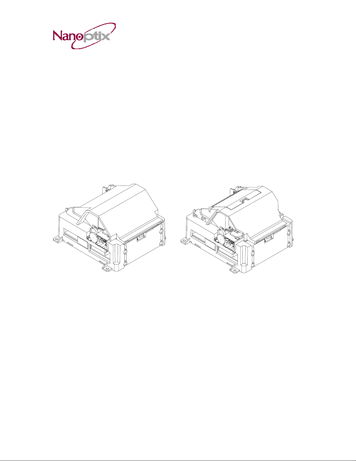
1.1 Description of Printer
The Nanoptix EZ-Tear thermal printers are extremely fast, quiet, and very reliable. With
thermal printing technology, there is no ribbon cassette to change, and paper loading is
extremely simple. The printer is small enough to fit almost anywhere and is easy to use
with the ticket exiting from the front.
102136
July, 2005
Figure 1: Nanoptix EZ-Tear-80 Printer (left), Nanoptix EZ-Tear-65 Printer (right)
1
Page 8

EZ-Tear Thermal Printer
Owner’s Manual
1.2 Models Available
There are several models of Nanoptix EZ-Tear printers available. Options include:
paper width, top of form, paper low, communication interface, left or right side and
spindle bucket. Please contact your representative for the most up-to-date options
available.
Connector Orientation
When installing your printer, please ensure that the connections and controls are
accessible during operation. The EZ-Tear printers can be ordered with the connectors
and controls on either the right or the left hand side of the printer.
Paper Exit (Front of Printer)
Communication
USB
Presenter or Buzzer (Optional)
102136
July, 2005
Power
Figure 2: Nanoptix EZ-Tear connection
(with connectors pictured on the Right side)
2
Page 9

1.3 General specifications
Print Method
Resolution
Print Width
Paper Width
Max Roll Diameter
Operating Temperature
Storage Temperature
Operating Relative Humidity
Communication Interface Options
Optional Interface
Memory/Firmware
Resident Character Sets
Integrated Bar Codes
Speed
Sensors
Human Interface
Dimensions
Weight
Emission Standards
Immunity Standards
EZ-Tear Thermal Printer
Owner’s Manual
Direct Thermal
8 dot/mm (203 dpi)
80mm
80mm or 65 mm
6” (152.4mm) on spindle, 4” (101.6mm) in
bucket
0 to 50 C
-40 C to +65 C
5% to 90% RH at 50C (non-condensing)
USB, RS-232C, RS-485, IEEE1284
None
1 Mbit of SRAM, 4 Mbit of flash and128Kbit
of EEPROM
Arial Bold (6 sizes)
Note: Other Character sets can be
programmed quickly
UPC-A, UPC-E, interleaved 2 of 5, 3 of 9,
Code 128, EAN 8, EAN 13.
Note: Other Bar Codes can be programmed
quickly
Up to 130 mm/second
• Paper out
• Door open
• Top of form (optional)
• Paper low (optional)
Status LED, paper feed button
131mm width x 82mm height x 133.5mm
depth
0.55 Kg
United States - FCC Part 15 Subpart B
Canada - Industry Canada ICES-003
Europe – EN 55022
Class A emissions
EN55024
102136
July, 2005
Table 1: Specification
3
Page 10

EZ-Tear Thermal Printer
Owner’s Manual
1.4 Installation
Mounting your printer
The Nanoptix EZTear printers have four 4.5mm mounting holes at the base that can be
used to mount the printer on a variety of surfaces. Please refer to the drawings in Figure
8 for proper hole spacing.
Note: The Nanoptix EZTear printers must be mounted on surfaces with a flatness of less
than 0.63mm (.025") total deviation. If the mounting surface in your application does not
meet the above specification (ex. shop grade plywood), please contact Nanoptix for
options that will ensure the proper functioning of your EZTear printer.
1.5 Printer Controls
To reset Printer
Simply plug and unplug the printer to reset in the event of a fault condition. Once the
Printer is re-plugged, it will go through a startup routine and resets itself. The LED will
light up. Note: there should be paper loaded in the printer and the door should be
closed.
102136
July, 2005
Power Connector
Figure 3: Resetting Printer
4
Page 11

Paper Feed Button
Use the Paper Feed Button to advance the paper.
EZ-Tear Thermal Printer
Owner’s Manual
102136
July, 2005
LED
Paper Feed
Button
Figure 4: Paper Feed Button
5
Page 12

A
EZ-Tear Thermal Printer
Owner’s Manual
1.6 Changing Paper
Caution: Do not operate the printer if it runs out of paper. The printer will not operate
without paper, but it may continue to accept data from the host computer. Because the
printer cannot print any transactions, the data may be lost.
1. Open the top cover by pulling under the tab on both sides.
2. Remove the used roll.
3. Tear off the end of the new roll so that the edge is loose and place the new roll into
the spindle bracket with a few inches of loose paper at the bottom of the roll.
Optional
Spindle bracket
lignment
Tabs
Figure 5: Loading Paper
Caution: The tear blade has sharp corners and caution should be exercised when
loading paper not to cause personal injury.
Notice: Be sure the paper unrolls from the bottom. Otherwise, the printer will not
Print.
102136
July, 2005
6
Page 13

EZ-Tear Thermal Printer
Owner’s Manual
4. Pull up on the bottom of the paper roll and align the paper properly before closing the
cover.
5. Advance the paper by pressing on the paper feed button and tear off the excess
paper.
Note: In the event of a paper jam, remove the roll, tear a new clean edge, and replace it
in the paper bucket, as described above. Be sure that the paper unrolls from the bottom
of the roll.
102136
July, 2005
7
Page 14

EZ-Tear Thermal Printer
Owner’s Manual
1.7 Testing the Printer
Run this test to check the printer. The test prints a resident test ticket. Verify this ticket to
judge the printing quality. This is an example, the printer’s actual status and associated
printout will vary depending upon the configuration shipped to you.
Model: EZ tear
Firmware: TI3-XXXXXXXXX
COMMUNICATION
Interface: IEEE1284 (0) or Serial
Baud: 9600
Data Bits: 8
Parity: NONE
Handshaking: NONE
Print Mode: NTL
Aux Port: Disabled
PRINT CONTROL
Darkness Control: -1%
Voltage: 24.2 Volts
Temperature: 26 Celcius
Speed: 4 IPS
Black Bar Index: Disabled
SYSTEM RESOURCES
FLASH -Used: 0
-Free: 24576
LIBRARY INVENTORY
Templates: 0,1,2
Print Regions: 1,2,3,4,5,6,7,8,
h,9,A,B,C,D,E,F,G,
I,J,K,L,N,O,P,Q,R,
S,T,U,Z,X,a,b,c,d,
e,f,g,i,j,k,l,m,n,
o,p,q,
Graphics: None
Fonts: 0,3,5,7,8
MANUFACTURING INFORMATION
Printer ID: 5465789
Date Code: 20184
PWM Setting: 7F7F7F7FFFFFFF
A to D: DE7AA400FD000000
Resets: 9
Tickets: 00001336
Status: TI3-XXXX- 0-40-40-40-40-P
Figure 6: Test Ticket
To print the test ticket, power-on the printer while pressing and holding the Paper Feed
Button for approximately 6 seconds. A test ticket similar to above will be printed
approximately 5 seconds after. Press the paper feed button once more and the ticket
will feed. Pressing the button again will result in blank tickets.
102136
July, 2005
8
Page 15

EZ-Tear Thermal Printer
Owner’s Manual
1.8 Troubleshooting the Printer
The printer is simple and generally trouble-free, but from time to time minor problems
may occur. Follow these procedures to determine the cause and resolution of any
problems the printer may be having. If the procedures in this section do not correct the
problem, contact a service representative. (1-888-983-3030 ext. 213)
Printer LED
Unit ready ON
Unit is in Reset or Booting OFF
Unit in standby (powered off) OFF
Paper Out Slow Blink
Door Open Fast Blink
Paper Jam Fast Blink
Missing Black Index Mark Fast Blink
Temperature Error Med Blink
Voltage Error Med Blink
Print Head Error Med Blink
Condition LED Status
Table 2: Troubleshooting with the status LED
Printing Problems
Problem Possible Causes What to Do
Receipt does not come
out all the way.
Printer starts to print,
but stops while the
receipt is being printed.
Print is light or spotty.
Vertical column of print
is missing.
One side of receipt is
missing.
Table 3: Troubleshooting Printing Problems
Paper is jammed. Open the top cover,
inspect and
clear any jammed paper.
Paper is jammed. Open the receipt cover,
inspect and
clear any jammed paper.
Paper roll loaded
incorrectly.
Thermal printhead is
dirty.
This indicates a serious
problem with the printer
electronics.
This indicates a serious
problem with the printer
electronics.
Check that the paper is
loaded properly.
Use recommended
thermal receipt paper.
Clean the Print Head
with Nanoptix authorized
cleaner.
Contact your authorized
service representative.
Contact your authorized
service representative.
102136
July, 2005
9
Page 16

Printer Does Not Work
Problem
Printer Does Not
Function When Turned
On.
Table 4: Printer Does Not Work
Possible Causes What to Do
Check that printer cables
are properly connected
Printer not plugged in.
Door not fully
Closed or paper not
loaded.
on both ends.
Check that the host or
power supply is switched
on. Check Printer LED.
Close the door and load
paper.
2. Media and Supplies Guide
EZ-Tear Thermal Printer
Owner’s Manual
2.1 Thermal Paper Specifications
The printer requires qualified thermal paper with the following dimensions:
Width Diameter
80 mm ± .2 mm (3.15 in. ± .008 in.)
or 65mm ± .2 mm ( 2.60 in. ± .008
in.)
Table 5: Thermal Paper Dimensions
152.4 mm max. (6 in.) when
using spindle, 101.6mm max
(4 in.) when using bucket
The paper must not be attached to the core. If Top of Form Option is installed, paper
with a black stripe (20% max reflectance) at the end of the roll can be used to indicate
that the paper is running low.
2.2 Ordering Thermal Paper
We recommend the following paper grades. There are a number of paper converters
qualified to supply this paper, provided the rolls are from these recommended grades.
Contact a Nanoptix sales representative if more information is required.
Manufacturer Numbers Paper Grade
Kanzaki Specialty Papers
(USA)
Tel: 888-526-9254
Fax: 413-731-8864
P-310 (Standard Sensitivity)
P-350 (High Sensitivity)
Table 6: Ordering Thermal Paper
102136
July, 2005
10
Page 17

EZ-Tear Thermal Printer
Owner’s Manual
2.3 Ordering Miscellaneous Supplies
Power Supply and Power Cord
Contact your sales representative to order the power supply and power cords listed in
the table. The numbers are for reference only. Suppliers may use other numbers.
Part Part Number
Power Supply (24VDC, 2.5A max., 60W) 100600-0004
Power Cord - North America 102080
Power Cord - Continental Europe 102086
Table 7: Power Supply and Power Cord Part Numbers
Ordering Communication Cables
Contact your sales representative to order the communication cables listed in the table.
These are Nanoptix part numbers. Suppliers may use other numbers.
Part Description Part Number
RS232 communication cable
(DB-9 male plug to DB-25 female receptacle)
Standard RS232 communication cable
(DB-9 male plug to DB-9 female receptacle)
Parallel communication cable
(IEEE 1284 Type C to A – Mini-Centronics to DB25)
USB communication cable
(Type mini B to A)
102107
102082
102084
102085
Table 8: Communication Cables Part Numbers
102136
July, 2005
11
Page 18

EZ-Tear Thermal Printer
Owner’s Manual
Communication Cables Pin-Out
The tables below detail the connection pin-out for the RS-232 interface (Female
Receptacle DB-9).
Pin Signal Name Printer I/O Host I/O Printer
Function
1 n/a 51R pull up to 5V Input Aux Power (low
current)
2 PRT_RS232_TXD Output Input Data transmit
3 PRT_RS232_RXD Input Output Data receive
4 n/a No connect Output None
5 Signal Ground Signal Ground Signal Ground Signal Ground
6 RS232_DSR Output Input Printer Ready/
Fault
7 PRT_RS232_CTS
(host RTS)
8 PRT_RS232_RTS
(host CTS)
9 n/a 100k pull up to 5V Input None
Shell Frame Ground Frame Ground Frame Gro un d Shield
Input Output Handshake
Output Input Handshake
Table 9: RS-232 Interface Pin-Out
102136
July, 2005
12
Page 19

EZ-Tear Thermal Printer
Owner’s Manual
3. Communicating with the Printer
Over the years, Nanoptix has developed emulations for compatibility with the most
popular printers in the market. At the time of printing this manual, the following
emulations are available:
- Epson 570 (for use with Windows™ XP or 2000 driver)
- Epson TM-T88III
- Star TUP-400
- Axiohm A722
- Ithaca P70
- Ithaca P170
- Citizen 3551
Please contact your sales representative if you require other emulations. If we do not
have the emulation you need, we can provide most emulations in a short timeframe. If
you are not required to emulate other printer, please ask your sales representative for
the latest Nanoptix Windows Driver or the “Nanoptix Programming Guide” which will list
the Nanoptix ESC/P commands.
102136
July, 2005
13
Page 20

EZ-Tear Thermal Printer
APPENDIX A: Mechanical Drawings
Owner’s Manual
102136
July, 2005
Figure 8: Mechanical Dimensions
(All dimensions in millimeters, tolerance +/-0.25mm)
14
Page 21

EZ-Tear Thermal Printer
Owner’s Manual
Figure 9: Mechanical Dimensions (Clearance for Cover)
(All dimensions in millimeters, tolerance +/-0.25mm)
102136
July, 2005
15
 Loading...