

Page 1

Confidential
Technical manual
Thermal printer unit
EU-T432
English
4013753
Issued Date
200 , ,
Issued by
Page 2

Rev. A i
Confidential
EU-T432 Technical Manual
CONFIDENTIALITY AGREEMENT
BY USING THIS DOCUMENT, YOU AGREE TO ABIDE BY THE TERMS OF THIS AGREEMENT.
PLEASE RETURN THIS
DOCUMENT IMMEDIATELY IF YOU DO NOT AGREE TO THESE TERMS.
❏ This document contains confidential, proprietary information of Seiko Epson Corporation or its affiliates. You
must keep such information con fident ial. If the us er is a busin ess en tity or org aniz ation, you mus t limit disclos ure
to those of your employees, agents and contractors who have a need to know and who are also bound by
obligations of confidentiality.
❏ On the earlier of (a) termination of your relationship with Seiko Epson, or (b) Seiko Epson’s request, you must
stop using the confidential information. You must then return or destroy the information, as directed by Seiko
Epson.
❏ If a court, arbitrator, government agen cy or t he like or ders you to disclos e a ny confid ent ial in forma ti on, you must
immediately notify Seiko Epson. You agree to give Seiko Epson reasonable cooperation and assistance in the
negotiation.
❏ You may use confidential information only for the purpose of operating or servicing the products to which the
document relates, unless you obtain the prior written consent of Seiko Epson for some other use.
❏ Seiko Epson warrants that it has the right to disclose the confidential information. SEIKO EPSON MAKES NO
OTHER WARRANTIES CONCERNING THE CONFIDENTIAL INFORMATION OR ANY OTHER
INFORMATION ON THE DOCUMENT, INCLUDING (WITHOUT LIMITATION) ANY WARRANTY OF TITLE
OR NON-INFRINGEMENT. Seiko Epson has no liability for loss or damage arising from or relating to your use of
or reliance on the information on the document.
❏ You may not reproduce, store or transmit the confidential information in any form or by any means (electronic,
mechanical, photocopying, recording, or otherwise) without the prior written permission of Seiko Epson.
❏ Your obligations under this Agreement are in addi tion to a ny other lega l obl iga ti ons. Seiko Epson does not wa iv e
any right under this Agreement by failing to exercise it. The laws of Japan apply to this Agreement.
Cautions
❏ Should any discrepancy exist between the contents of this document and the provisions of the "Master Contract"
or "Specifications," the latter shall take precedence over the former.
❏ We shall not be responsible for any troubles that might occur from the application of this document by customer
either to a machine other than this product, or to a drive circuit or other device that is the industrial property of a
third party.
❏ No part of this document may be reproduced, stored in a retrieval system, or transmitted in any form or by any
means, electronic, mechanical, photocopying, recording, or otherwise, without the prior written permission of
Seiko Epson Corporation.
❏ The contents of this document are subject to change without notice. Please contact us for the latest information.
❏ While every precaution has been taken in the prepa ra ti on of t his d ocument, Seiko Epson Corporation assumes no
responsibility for errors or omissions.
❏ Neither is any liability assumed for damages resulting from the use of the information contained herein.
❏ Neither Seiko Epson Corporation nor its affiliates shall be liable to the purchaser of this product or third parties
for damages, loss es, c osts, or expe nses i ncu rred by the purcha se s or thi rd par ties as a resu lt of: acci dent, m isus e, or
abuse of this product or unauthoriz ed modifi cation s, repairs , or a lterations to th is product , or (excludin g the U. S.)
failure to strictly comply with Seiko Epson Corporation’s operating and maintenance instructions.
❏ Seiko Epson Corporation shall not be liable against any damages or problems arising from the use of any options
or any consumable products other than those designated as Original EPSON Products or EPSON Approved
Products by Seiko Epson Corporation.
Page 3

ii Rev. A
Confidential
Trademarks
EPSON® is a registered trademark of Seiko Epson Corporation.
General Notice: Other product and company names used herein are for identification purposes only and may be
trademarks of their respective companies.
Points That Must Be Observed
To Assure Product Safety
To assure the safe operation of this product, carefully observe the specifications as well as the notes provided below.
Seiko Epson Corporation will not bear any responsibility for any damage or injuries arising from use of this product
that is not in accordance with the specifications and the notes provided below.
Notes on Head Control
❏ The conditions setting forth the maximum time power can be applied (and the maximum voltage that can be
applied) to electronic components such as the head, motor, and magnets must be observed.
If the maximum time power can be applied (or the maximum voltage that can be applied) is exceeded, the components
mentioned above could overheat and start a fire or beg i n to smoke.
❏ Always include protective circuitry governing the length of time power is applied and the amount of current that
is applied when designing the drive and control circuits for the head, motor, magnets, etc.
If protective circuitry is not included, misoperation of the printer control circuits could cause the comp onents mentioned
above to overheat and begin to smoke or burn.
Notes on Handling
❏ The case must be designed so that movable parts, such as gears, are not exposed.
Touching moving parts could cause a laceration or other injury.
Page 4

Rev. A iii
Confidential
EU-T432 Technical Manual
About This Manual
This manual consists of the following chapters.
Symbols
Notes in this manual are identified by their level of importance, as defined below.
CAUTION:
Observe cautions to avoid minor injury to yourself, damage to your equipment, or loss of
data.
Note:
Notes have important information and useful tips on the operation of your equipment.
Chapter 1
Features and Specifications
This chapter contains features and general specifications for
the EU-T432.
Chapter 2
Operation Principle
This chapter contains the outline and principles of
mechanisms.
Chapter 3
Handling
This chapter contains precauti ons on handling, pa per loading
and unloading and removing jammed paper.
Chapter 4
Maintenance
This chapter contains information on cleaning, inspection,
lubrication, and tools.
Chapter 5
Repair
This chapter contains repair levels, repair procedures, and
troubleshooting.
Chapter 6
Assembly and Disassembly
This chapter contains assembly and disassembly for the unit s
and modules of the EU-T432.
Appendix
The appendix contains the exploded and adhesive diagrams
of the EU-T432.
Page 5

iv Rev. A
Confidential
Contents
About This Manual . . . . . . . . . . . . . . . . . . . . . . . . . . . . . . . . . . . . . . . . . . . . . . . . . . . . v
Symbols . . . . . . . . . . . . . . . . . . . . . . . . . . . . . . . . . . . . . . . . . . . . . . . . . . . . . . . . . . . . . . v
Chapter 1
Features and Specifications
Features . . . . . . . . . . . . . . . . . . . . . . . . . . . . . . . . . . . . . . . . . . . . . . . . . . . . . . . . . . . . . . 1-1
System Configuration and Module Names . . . . . . . . . . . . . . . . . . . . . . . . . . . . . . . . 1-2
Specifications . . . . . . . . . . . . . . . . . . . . . . . . . . . . . . . . . . . . . . . . . . . . . . . . . . . . . . . . . 1-3
Module Combinations and Specifications: . . . . . . . . . . . . . . . . . . . . . . . . . . . . . 1-4
Chapter 2
Operation Principles
Outline of Mechanism . . . . . . . . . . . . . . . . . . . . . . . . . . . . . . . . . . . . . . . . . . . . . . . . . . 2-1
Paper Roll Supply Module . . . . . . . . . . . . . . . . . . . . . . . . . . . . . . . . . . . . . . . . . . . . . . 2-1
Paper Holding Section . . . . . . . . . . . . . . . . . . . . . . . . . . . . . . . . . . . . . . . . . . . . . . 2-2
Paper Load-absorbing Mechanism . . . . . . . . . . . . . . . . . . . . . . . . . . . . . . . . . . . 2-2
Paper NE Detector . . . . . . . . . . . . . . . . . . . . . . . . . . . . . . . . . . . . . . . . . . . . . . . . . 2-2
Printer Module . . . . . . . . . . . . . . . . . . . . . . . . . . . . . . . . . . . . . . . . . . . . . . . . . . . . . . . . 2-3
Drive Force Transmission Mechanism . . . . . . . . . . . . . . . . . . . . . . . . . . . . . . . . 2-3
Paper Feed Mechanism . . . . . . . . . . . . . . . . . . . . . . . . . . . . . . . . . . . . . . . . . . . . . 2-4
Printing Mechanism . . . . . . . . . . . . . . . . . . . . . . . . . . . . . . . . . . . . . . . . . . . . . . . . 2-6
Paper Guide Mechanism . . . . . . . . . . . . . . . . . . . . . . . . . . . . . . . . . . . . . . . . . . . . 2-8
Detector Mechanism . . . . . . . . . . . . . . . . . . . . . . . . . . . . . . . . . . . . . . . . . . . . . . . 2-8
Autocutter Mechanism . . . . . . . . . . . . . . . . . . . . . . . . . . . . . . . . . . . . . . . . . . . . . 2-11
Cut Sheet Presenter Module . . . . . . . . . . . . . . . . . . . . . . . . . . . . . . . . . . . . . . . . . . . . . 2-15
Paper Carrying Operation (With a Loop) . . . . . . . . . . . . . . . . . . . . . . . . . . . . . . 2-15
Paper Carrying Operation (Without a Loop) . . . . . . . . . . . . . . . . . . . . . . . . . . . 2-17
Detector Mechanism . . . . . . . . . . . . . . . . . . . . . . . . . . . . . . . . . . . . . . . . . . . . . . . 2-17
Control Circuit Board Module . . . . . . . . . . . . . . . . . . . . . . . . . . . . . . . . . . . . . . . . . . . 2-18
DIP Switches . . . . . . . . . . . . . . . . . . . . . . . . . . . . . . . . . . . . . . . . . . . . . . . . . . . . . . 2-18
Memory Switches . . . . . . . . . . . . . . . . . . . . . . . . . . . . . . . . . . . . . . . . . . . . . . . . . . 2-20
Chapter 3
Handling
Precautions . . . . . . . . . . . . . . . . . . . . . . . . . . . . . . . . . . . . . . . . . . . . . . . . . . . . . . . . . . . 3-1
Transport Precautions . . . . . . . . . . . . . . . . . . . . . . . . . . . . . . . . . . . . . . . . . . . . . . 3-1
Carrying Precautions . . . . . . . . . . . . . . . . . . . . . . . . . . . . . . . . . . . . . . . . . . . . . . . 3-1
Installation Precautions . . . . . . . . . . . . . . . . . . . . . . . . . . . . . . . . . . . . . . . . . . . . . 3-2
Handling Precautions . . . . . . . . . . . . . . . . . . . . . . . . . . . . . . . . . . . . . . . . . . . . . . 3-2
Storage Precautions . . . . . . . . . . . . . . . . . . . . . . . . . . . . . . . . . . . . . . . . . . . . . . . . 3-4
Opening and Closing Modules, Unit and Part . . . . . . . . . . . . . . . . . . . . . . . . . . . . . 3-4
Paper Roll Supply Module . . . . . . . . . . . . . . . . . . . . . . . . . . . . . . . . . . . . . . . . . . 3-4
Platen Unit . . . . . . . . . . . . . . . . . . . . . . . . . . . . . . . . . . . . . . . . . . . . . . . . . . . . . . . . 3-4
Cut Sheet Presenter Module . . . . . . . . . . . . . . . . . . . . . . . . . . . . . . . . . . . . . . . . . 3-5
Paper guide, upper . . . . . . . . . . . . . . . . . . . . . . . . . . . . . . . . . . . . . . . . . . . . . . . . . 3-5
Loading and Removing Paper roll . . . . . . . . . . . . . . . . . . . . . . . . . . . . . . . . . . . . . . . . 3-6
Loading a Paper roll . . . . . . . . . . . . . . . . . . . . . . . . . . . . . . . . . . . . . . . . . . . . . . . . 3-6
Removing Paper . . . . . . . . . . . . . . . . . . . . . . . . . . . . . . . . . . . . . . . . . . . . . . . . . . . 3-9
Removing Jammed Paper . . . . . . . . . . . . . . . . . . . . . . . . . . . . . . . . . . . . . . . . . . . . . . . 3-9
Removing Jammed Paper From the Cut Sheet Presenter Module . . . . . . . . . 3-9
Removing Jammed Paper From the Printer Module . . . . . . . . . . . . . . . . . . . . 3-10
Paper NE Detector Setting . . . . . . . . . . . . . . . . . . . . . . . . . . . . . . . . . . . . . . . . . . . . . . 3-10
Self Test . . . . . . . . . . . . . . . . . . . . . . . . . . . . . . . . . . . . . . . . . . . . . . . . . . . . . . . . . . . . . . 3-12
Performing the Self Test . . . . . . . . . . . . . . . . . . . . . . . . . . . . . . . . . . . . . . . . . . . . 3-12
Self Test End . . . . . . . . . . . . . . . . . . . . . . . . . . . . . . . . . . . . . . . . . . . . . . . . . . . . . . 3-12
Errors . . . . . . . . . . . . . . . . . . . . . . . . . . . . . . . . . . . . . . . . . . . . . . . . . . . . . . . . . . . . . . . . 3-13
Page 6

Rev. A v
Confidential
EU-T432 Technical Manual
LED Display . . . . . . . . . . . . . . . . . . . . . . . . . . . . . . . . . . . . . . . . . . . . . . . . . . . . . . 3-13
POWER LED (Power Supply Error): Green . . . . . . . . . . . . . . . . . . . . . . . . . . . 3-13
PAPER LED (Paper-End Error): Red . . . . . . . . . . . . . . . . . . . . . . . . . . . . . . . . . 3-13
ERROR LED (Error): Red . . . . . . . . . . . . . . . . . . . . . . . . . . . . . . . . . . . . . . . . . . . 3-13
Chapter 4
Maintenance
Cleaning . . . . . . . . . . . . . . . . . . . . . . . . . . . . . . . . . . . . . . . . . . . . . . . . . . . . . . . . . . . . . 4-1
Thermal Head Cleaning . . . . . . . . . . . . . . . . . . . . . . . . . . . . . . . . . . . . . . . . . . . . 4-1
Removing Stains (Except for the Thermal Head) . . . . . . . . . . . . . . . . . . . . . . . 4-2
Removing Dirt and Dust . . . . . . . . . . . . . . . . . . . . . . . . . . . . . . . . . . . . . . . . . . . 4-2
Removing Foreign Matter When the Cutter Locks . . . . . . . . . . . . . . . . . . . . . . 4-2
Inspection . . . . . . . . . . . . . . . . . . . . . . . . . . . . . . . . . . . . . . . . . . . . . . . . . . . . . . . . . . . . 4-3
Daily Checks . . . . . . . . . . . . . . . . . . . . . . . . . . . . . . . . . . . . . . . . . . . . . . . . . . . . . . 4-3
Periodic Checks . . . . . . . . . . . . . . . . . . . . . . . . . . . . . . . . . . . . . . . . . . . . . . . . . . . 4-3
Lubrication . . . . . . . . . . . . . . . . . . . . . . . . . . . . . . . . . . . . . . . . . . . . . . . . . . . . . . . . . . . 4-4
Lubricant . . . . . . . . . . . . . . . . . . . . . . . . . . . . . . . . . . . . . . . . . . . . . . . . . . . . . . . . . 4-4
Lubrication Standards . . . . . . . . . . . . . . . . . . . . . . . . . . . . . . . . . . . . . . . . . . . . . . 4-4
Lubrication Point . . . . . . . . . . . . . . . . . . . . . . . . . . . . . . . . . . . . . . . . . . . . . . . . . . 4-4
Lubricant List . . . . . . . . . . . . . . . . . . . . . . . . . . . . . . . . . . . . . . . . . . . . . . . . . . . . . 4-5
Tools . . . . . . . . . . . . . . . . . . . . . . . . . . . . . . . . . . . . . . . . . . . . . . . . . . . . . . . . . . . . . . . . 4-5
Chapter 5
Repair
Repair Levels . . . . . . . . . . . . . . . . . . . . . . . . . . . . . . . . . . . . . . . . . . . . . . . . . . . . . . . . . 5-1
Repair Procedure . . . . . . . . . . . . . . . . . . . . . . . . . . . . . . . . . . . . . . . . . . . . . . . . . . . . . . 5-1
Troubleshooting . . . . . . . . . . . . . . . . . . . . . . . . . . . . . . . . . . . . . . . . . . . . . . . . . . . . . . . 5-2
Chapter 6
Assembly and Disassembly
Small Parts Abbreviation . . . . . . . . . . . . . . . . . . . . . . . . . . . . . . . . . . . . . . . . . . . . . . . 6-1
Disassembly . . . . . . . . . . . . . . . . . . . . . . . . . . . . . . . . . . . . . . . . . . . . . . . . . . . . . . . . . . 6-2
Assembly . . . . . . . . . . . . . . . . . . . . . . . . . . . . . . . . . . . . . . . . . . . . . . . . . . . . . . . . . . . . . 6-2
Installation of the Printer Module . . . . . . . . . . . . . . . . . . . . . . . . . . . . . . . . . . . . 6-3
Pre-assembly A: Paper guide,straight, back unit . . . . . . . . . . . . . . . . . . . 6-3
Pre-assembly B: Frame, platen, straight unit, B . . . . . . . . . . . . . . . . . . . . 6-4
Pre-assembly C: Cutter motor assembly . . . . . . . . . . . . . . . . . . . . . . . . . . 6-7
Pre-assembly D: Cutter, cover sub-unit . . . . . . . . . . . . . . . . . . . . . . . . . . . 6-8
Pre-assembly E: Cutter unit, B . . . . . . . . . . . . . . . . . . . . . . . . . . . . . . . . . . . 6-11
Pre-assembly F: Black mark detector sub-assembly (option) . . . . . . . . . 6-13
Main Assembly A: Motor, paper feed, receipt, B and Platen detector . 6-14
Main Assembly B: Paper guide, straight, front and Paper guide, straight, back unit
. . . . . . . . . . . . . . . . . . . . . . . . . . . . . . . . . . . . . . . . . . . . . . . . . . . . . . . . . . . . . . 6-16
Main Assembly C: Frame, platen, straight unit . . . . . . . . . . . . . . . . . . . . 6-18
Main Assembly D: Thermal print head assembly. . . . . . . . . . . . . . . . . . . 6-20
Main Assembly E: Plate, pressure spring. . . . . . . . . . . . . . . . . . . . . . . . . . 6-21
Main Assembly F: Fixing plate, the Gear, reduction and Gear, idler . . 6-23
Main Assembly G: Cutter unit . . . . . . . . . . . . . . . . . . . . . . . . . . . . . . . . . . . 6-24
Assembly H: Arranging the lead wires . . . . . . . . . . . . . . . . . . . . . . . . . . . 6-25
Main Assembly I: Cable, printer and Cable, head . . . . . . . . . . . . . . . . . . 6-26
Assembly J: Black mark detector Adjustment . . . . . . . . . . . . . . . . . . . . . . 6-27
Main Assembly K: Cover, cable . . . . . . . . . . . . . . . . . . . . . . . . . . . . . . . . . . 6-28
Main Assembly L: Cover, gear . . . . . . . . . . . . . . . . . . . . . . . . . . . . . . . . . . 6-29
Page 7

vi Rev. A
Confidential
Installation of the Other Modules . . . . . . . . . . . . . . . . . . . . . . . . . . . . . . . . . . . . 6-30
Pre-assembly A: Frame, paper supply assembly . . . . . . . . . . . . . . . . . . . . 6-30
Pre-assembly B: Roll paper holder unit . . . . . . . . . . . . . . . . . . . . . . . . . . . 6-34
Pre-assembly C: Roll paper supply module . . . . . . . . . . . . . . . . . . . . . . . . 6-39
Pre-assembly D: Presenter table assembly . . . . . . . . . . . . . . . . . . . . . . . . . 6-40
Pre-assembly E: Presenter frame, right assembly . . . . . . . . . . . . . . . . . . . 6-41
Pre-assembly F: Presenter frame, left assembly . . . . . . . . . . . . . . . . . . . . . 6-42
Pre-assembly G: Paper guide assembly . . . . . . . . . . . . . . . . . . . . . . . . . . . 6-43
Pre-assembly H: Cutting sheet presenter module . . . . . . . . . . . . . . . . . . . 6-44
Main Assembly A: Printer module . . . . . . . . . . . . . . . . . . . . . . . . . . . . . . . 6-49
Main Assembly B: Cut sheet presenter module . . . . . . . . . . . . . . . . . . . . . 6-52
Main Assembly C: Roll paper supply module . . . . . . . . . . . . . . . . . . . . . . 6-53
Main Assembly D: Control circuit board and Cover, circuit boards
upper/ lower . . . . . . . . . . . . . . . . . . . . . . . . . . . . . . . . . . . . . . . . . . . . . . . . . 6-54
Main Assembly E: Roll paper shaft assembly . . . . . . . . . . . . . . . . . . . . . . 6-57
Appendix
EU-T432 Exploded Diagram . . . . . . . . . . . . . . . . . . . . . . . . . . . . . . . . . . . . . . . . . . . . . 1
Printer Module Exploded Diagram . . . . . . . . . . . . . . . . . . . . . . . . . . . . . . . . . . . . . . . 2
Cut Sheet Presenter Module Exploded Diagram . . . . . . . . . . . . . . . . . . . . . . . . . . . 3
Roll Paper Supply Module Exploded Diagram . . . . . . . . . . . . . . . . . . . . . . . . . . . . . 4
EU-T432 Lubrication Diagram . . . . . . . . . . . . . . . . . . . . . . . . . . . . . . . . . . . . . . . . . . . 5
Printer Module Lubrication Diagram . . . . . . . . . . . . . . . . . . . . . . . . . . . . . . . . . . . . . 6
Cut Sheet Presenter Module Lubrication Diagram . . . . . . . . . . . . . . . . . . . . . . . . . . 7
Roll Paper Supply Module Adhesive Diagram . . . . . . . . . . . . . . . . . . . . . . . . . . . . . 8
Page 8

Rev. A Features and Specifications 1-1
EU-T432 Technical Manual
Confidential
Chapter 1
Features and Specifications
Features
The EU-T432 is designed to be used for kiosks and cash dispensers. The featur es of th e EU-T43 2
are as follows:
❏ High speed receipt issuing: 150 mm/s {5.9"/s} maximum
❏ High reliability: 300,000 receipt issue
❏ Length of receipt: 228.4 mm {9"} maximum
(When the EU-T432 is equipped with an optional loop guide: 600 mm {23.6"}
❏ Available for large paper roll core dimensions:
203 mm {8"} diameter maximum
❏ Supports ESC/POS
equivalent commands
❏ Able to print bar codes (fence and ladder) and graphics
❏ Options available for all models:
• Japanese Kanji model: Supports JIS Level 1 and 2
• Simple Chinese model: Supports GB50007-85
• Traditional Chinese model: Supports BIG5 Level 1 and 2
• Korean model: Supports C-6501C
❏ Driver and status monitor are available.
Page 9

1-2 Features and Specifications Rev. A
Confidential
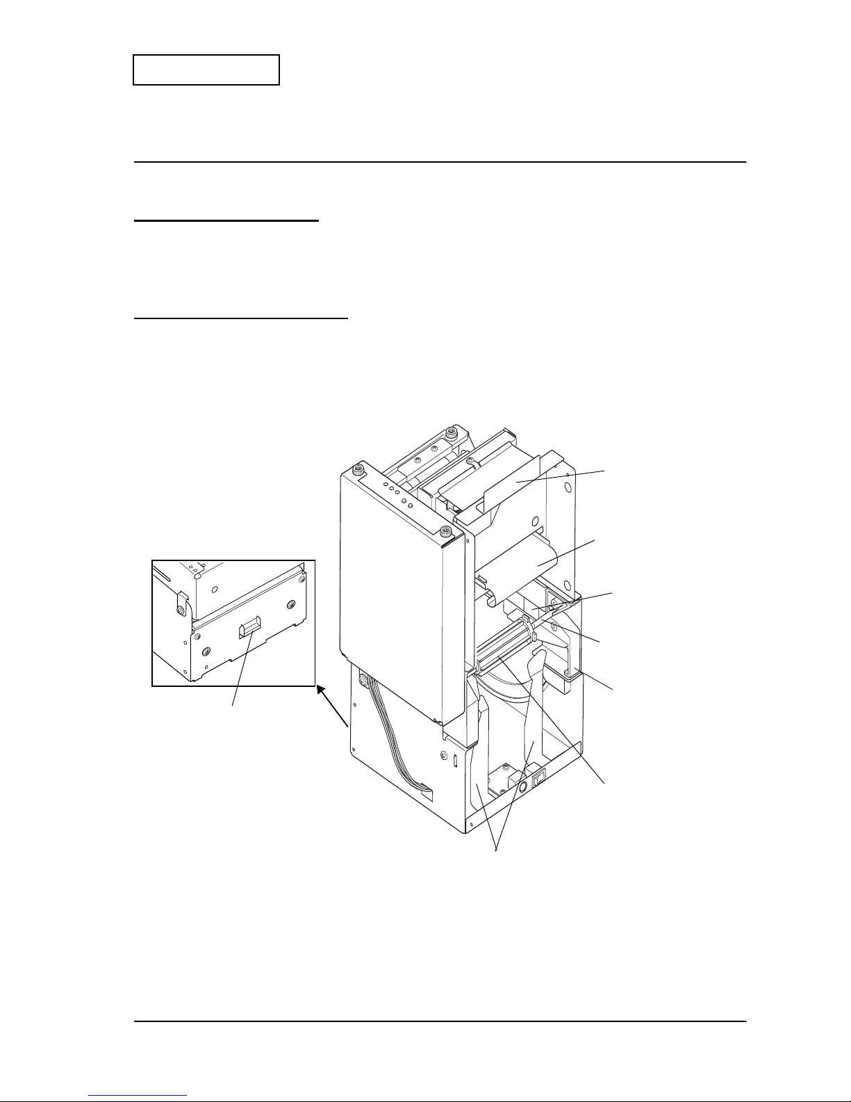
System Configuration and Module Names
The whole systems is called the “EU-T432.” The EU-T432 consists of four modules and the
configuration of the modules are shown below:
Figure 1-1 EU-T432 appearance
paper roll supply modu le
cut sheet presenter module
control circuit board
module
printer module
Page 10

Rev. A Features and Specifications 1-3
EU-T432 Technical Manual
Confidential
Specifications
The basic specifications of the EU-T432 are shown below. Refer to the specifications for the
EU-T432 issued by Seiko Epson Corporation for more details.
Table 1.1 Specifications
Item
Specification
Paper roll Outside diameter
152.4 mm {6"}
(When equipped with an optional part: 2 0 3 mm {8"))
Paper width
79.5 ± 0.5 mm {3.13 ± 0.02"}
Paper carrying speed
150 mm/s {5.9"/s} maximum
Paper length to be
presented
Issuing the cut sheet
(Receipt printing)
When the cut sheet is looped: 76.2 to 228.6 mm {3 to 9"}
When equipped with an optional loop guide:
76.2 to 600 mm {3 to 23.6"}
When the cut sheet is not looped:
76.2 to 3000 mm {3 to 118.1"}
Print speed
150 mm/s {5.9"/s} maximum
Print width
72 mm {2.84"} maximum (recommended)
Reliability Receipt printing
300,000 times
Printer
Mechanism: 15,000,000 lines
Thermal head: 100 km {62.14 miles},
100 million pulses
Paper roll Specified thermal paper
Original paper No.: P350 KSP
Original paper No.: TF50KS-E NIPPON PAPER
INDUSTRIES CO.,LTD
Original paper No.: PD160R
OJI PAPER MFG.CO., LTD
Original paper No.: TF11KS-ET NIPPON PAPER
INDUSTRIES CO.,LTD
Original paper No.: TF51KS-X1 NIPPON PAPER
INDUSTRIES CO.,LTD
Original paper No.: PD200N
OJI PAPER MFG.CO., LTD
Original paper No.: AFP234 MITSUBISHI PAPER MILLS
CO., LTD
A different paper type may give a different print
quality.
Paper thickness 60 to 150 µm
If the paper thickness is more than 120 µm, the paper
loop must not be used.
Page 11
1-4 Features and Specifications Rev. A
Confidential
Module Combinations and Specifications:
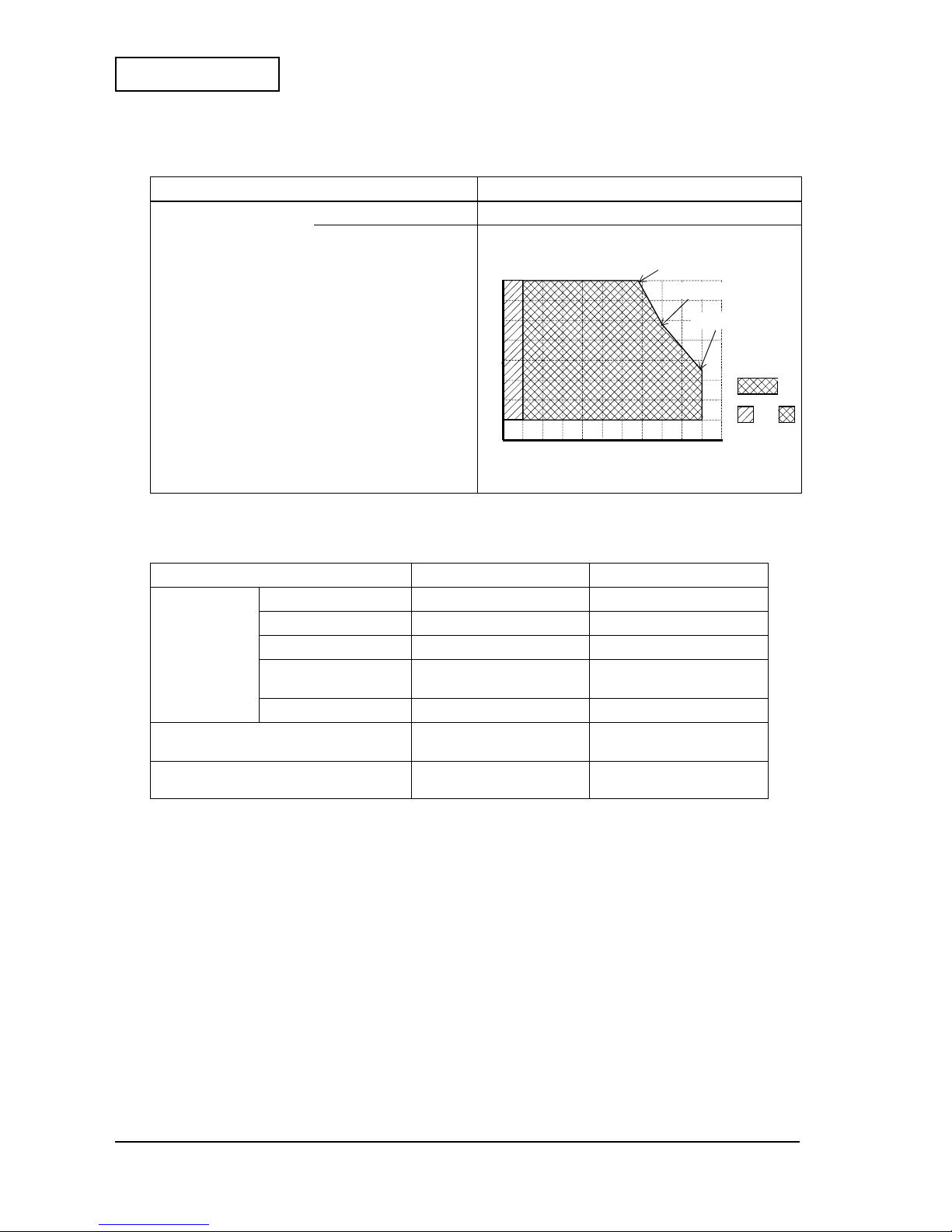
Environmental condition Operating temperat ure 0 to 50°C
Operating humidity 10 to 80% RH
Table 1-2 Module Combinations and Specifications
Item
6 inch type
8 inch type
Combination of
each module
Paper roll module
Yes Yes
Printer module
Yes Yes
Control board module
Yes Yes
Cut sheet presenter
module
Yes Yes
Paper supply spacer
Yes
Mass
Approximatel y 3.8 kg
{8.38 lb}
Approximatel y 3.9 kg
{8.60 lb]
External dimensions (W × D × H): mm
194.7
×
170.6
×
300
{7.7
×
6.7
×
11.8"}
194.7 × 170.6
×
350
{7.7 × 6.7 × 13.8"}
Table 1.1 Specifications
Item
Specification
80
50
10
0
0 5 10 20 30 40 5550
34°C 80%
40°C 58%
50°C 35%
Print quality is
guaranteed.
+
Operation is
guaranteed.
Page 12
Rev. A Operation Principles 2-1
EU-T432 Technical Manual
Confidential
Chapter 2
Operation Principles
Outline of Mechanism
The EU-T432 consists o f f our mo dule s: the paper rol l suppl y modu le, t he pri nter module, the cut
sheet presenter module, and the control circuit board module.
Paper Roll Supply Module
The paper roll supply module holds a large diameter paper roll and gu ides the paper to the
printer mod ule. This modu le consists of the paper holding part, the paper load-absorbing
mechanism, and the paper near-end detector. The appearance of this module is shown below.
Figure 2-1 Paper roll supply module appearance
lever, open
paper NE detector
shaft, roll paper
holder, roll paper A
holder, roll paper shaft
guide, roll paper tensio n
plate, opening and
shutting
holder, roll paper shaft
plate, roll paper guide
Page 13

2-2 Operation Principles Rev. A
Confidential
Paper Holding Section
The paper roll holding mechanism is a shaft support type. The paper roll holding section
consists of the removable
shaft, roll paper
, the
holder, roll paper A
(for the inner diameter of
the paper core: 25.4 mm {1 i nch}) that fits the size of the paper roll core used, the
holder, roll
paper shaft
that supports the
shaft, roll pap er
and the
plate, roll paper guide
that holds the
sides of the paper roll.
The paper holding sectio n turn s on a fi xed screw sec tion so that t he paper holding sectio n can be
opened and closed. The paper holding section can be opened by pulling down the
plate,
opening and shutting
while holdin g down the
lever, open
. When closing the paper holding
section, pull up the
plate, opening and shutting
causing the
lever, open
to be locked
automatically; then the paper holding section is closed securely.
Note:
If the paper inner core dimension differs from the
holder, roll paper A
due to the paper thickness, you
can replace it with an optional holder, a
holder, roll paper B
(for the inner diameter of the paper core:
50.8 mm {2 inch}) or a
holder, paper roll C
(for the inner diameter of the paper core: 76.2 mm {3
inch}).
Paper Load-absorbing Mechanism
The paper load-absorbing mechanism consists of the
guide, roll paper tension
that receives
the paper tension. Using the paper tensile force generated when feeding the paper, this
mechanism oscillates the
guide, roll paper tension
and reduces the paper feeding load due to
inertia of the paper roll.
Paper NE Detector
The
paper NE detector
has two kind of detections, the primary NE detection and the
secondary NE detection. The primary NE detection can detect the amount remaining on the
paper roll using a reflecting photo sensor. After the primary NE detection, the secondary
detection can be used to return the status when the paper is fed to the length specified by the
memory switch setting. (See SW No. 2, 3 in Table 2-10 on page 2-20.)
The
paper NE detector
is mounted on the
frame
and is secured with a screw. The position of
the
paper NE detector
can be altered to adjust the setting for the amount remaining on the
paper roll.
Page 14

Rev. A Operation Principles 2-3
EU-T432 Technical Manual
Confidential
Printer Module
The printer module has a printing mechanism with the paper feeding and a cutting mechanism
to cut the paper.
The printer consists of the following six mechanisms: the drive force transmission mechanism,
the paper feed mechanism, the printing mechanism, the paper guide mechanism, the detector
mechanism, and the autocutter mechanism.
Figure 2-2 Printer module appearance
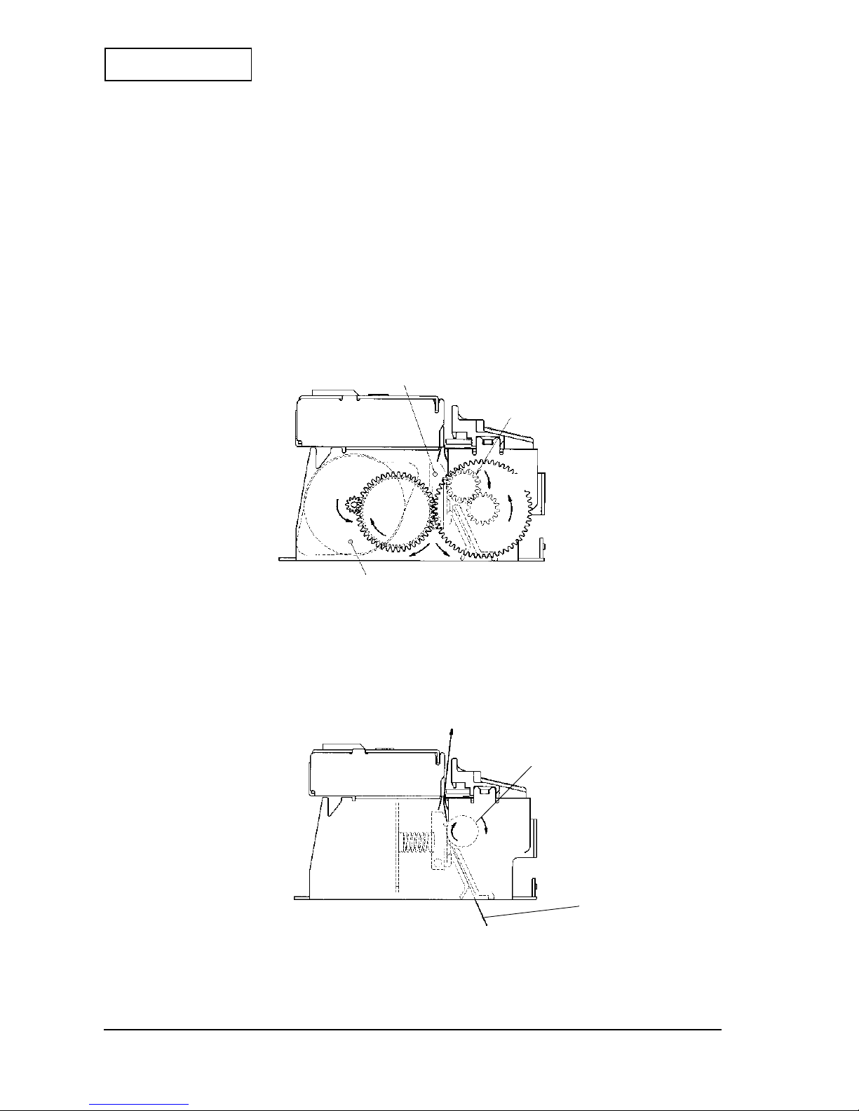
Drive Force Transmission Mechanism
This mechanism consists of the
motor, paper feed, receipt, B
(fixed to pinion), the
gear,
reduction
, the
gear, idle r
, and the
gear, platen
. The printer uses a stepping motor, the
rotation force of which is reduced in sequence by the
gear, reduction
and the
gear, idl er
before being transmitted to the
gear, platen
. (The arrows in the figure below indicate the
direction of the gear rotation.) The
gear, platen
is mounted to the frame platen unit and
separates from the
gear, idle r
when the
platen
is open.
Figure 2-3 Drive force transmission mechanism
gear, platen
gear, idler
gear, reduction
motor, paper feed, receipt, B
Page 15
2-4 Operation Principles Rev. A
Confidential
This printer uses a 4-phase bi-polar stepping motor driven by 24 V voltage controlled 2-2 phase
excitation. The maximum drive frequency of 2-2 phase excitation is 1200 pps. [pps: pulses per
second]
Paper Feed Mechanism
This mechanism consists of the paper feed mechanism and the platen-open mechanism.
Paper feed mechanis m
The paper feed mechanism consists of the
platen
(paper feed roller) and the
thermal head
.
When the
motor, paper feed, receipt, B
rotates counterclockwise as viewed from the shaft,
the gear train transmits the motion to the
platen
which rotates in direction A.
Figure 2-4 Paper feed mechanism
Paper feed operation during prin ting
The
platen
presses the thermal paper against the
thermal head
with a constant force. When
the
platen
rotates in direction A, the thermal paper advances in direction B.
Figure 2-5 Paper feed operation during printing
thermal head
platen
motor, paper feed, receipt, B
A
B
platen
thermal paper
A
Page 16
Rev. A Operation Principles 2-5
EU-T432 Technical Manual
Confidential
Platen-open mechanism
The platen-open mechanism is used for the following purposes:
• Paper loading when using the printer with the curved path type. (Excluding when
using semi-autoloading mode.)
• Removing a paper jam when the paper jam has occurred
• The
thermal head
and the
platen
cleaning
The mechanism consists of the
frame, platen
, the
lever, platen
, the
shaft, platen
, the
spring,
lever
, the
lock lever
, the
spring, lock lever
, and the
pushplate , p l aten, B
.
In the
frame, platen
, the
platen
is mounted. The
lever, platen
is operated by hand to open t he
frame platen unit. The
shaft, platen
connects the
lever, platen
and the
frame, platen
to the
frame, base
in a manner which allows them to rotate. The
spring, lever
pulls the
lever,
platen
in the opposite direction of arrow A when the
platen
is open. The
lock lever
is located
on the gear train side of the
frame, platen
and locks the frame platen unit to the
frame, base
.
The
spring, lock lever
(inside the
lock lever
) pushes the
lock lever
back. The
pushplate,
platen, B
is secured on top of the
frame, platen
and covers the
fixed blade
.
When the frame platen unit is closed, the
platen
is in the print- ready position where the
gear,
platen
and the
gear, idler
are engaged and the power can be transmitted readily. Also, the
lock lever
is locked at a part of the
frame, base
to prevent the gears from disengaging.
To open the
platen
, turn the
lever, platen
in the direction of arrow A as shown in Figure 2-6.
Simultaneously, the
lock lever
is released and the frame platen unit is opened. To close the
platen
, turn the
lever, platen
in the opposite direction of arrow A until the lever stops.
Figure 2-6 Platen-open mechanism
frame, platen
shaft, platen
frame, base
spring, lock leve r
spring, lever
lever, platen
lock lever
gear, idler
gear, platen
A
< platen-open >
< platen-close >
push plate, platen, B
*The cover, gear is removed in these figures.
Page 17
2-6 Operation Principles Rev. A
Confidential
Printing Mechanism
This mechanism consists of the
thermal head
which has the head heating elements a rrange d in
a series and has a driver IC for controlling voltage to the head heating elements, the
platen
which is also used for the paper feed mechanism as well as this mechanism (the
thermal head
is also used for both mechanisms), and the
spring, press head
. The
platen
presses the thermal
paper wrapped around the
platen
against the head heating elements pressed by the
spring,
press head
. When the elements are activated, the paper is heated at the designated points,
resulting in the printing actio n.
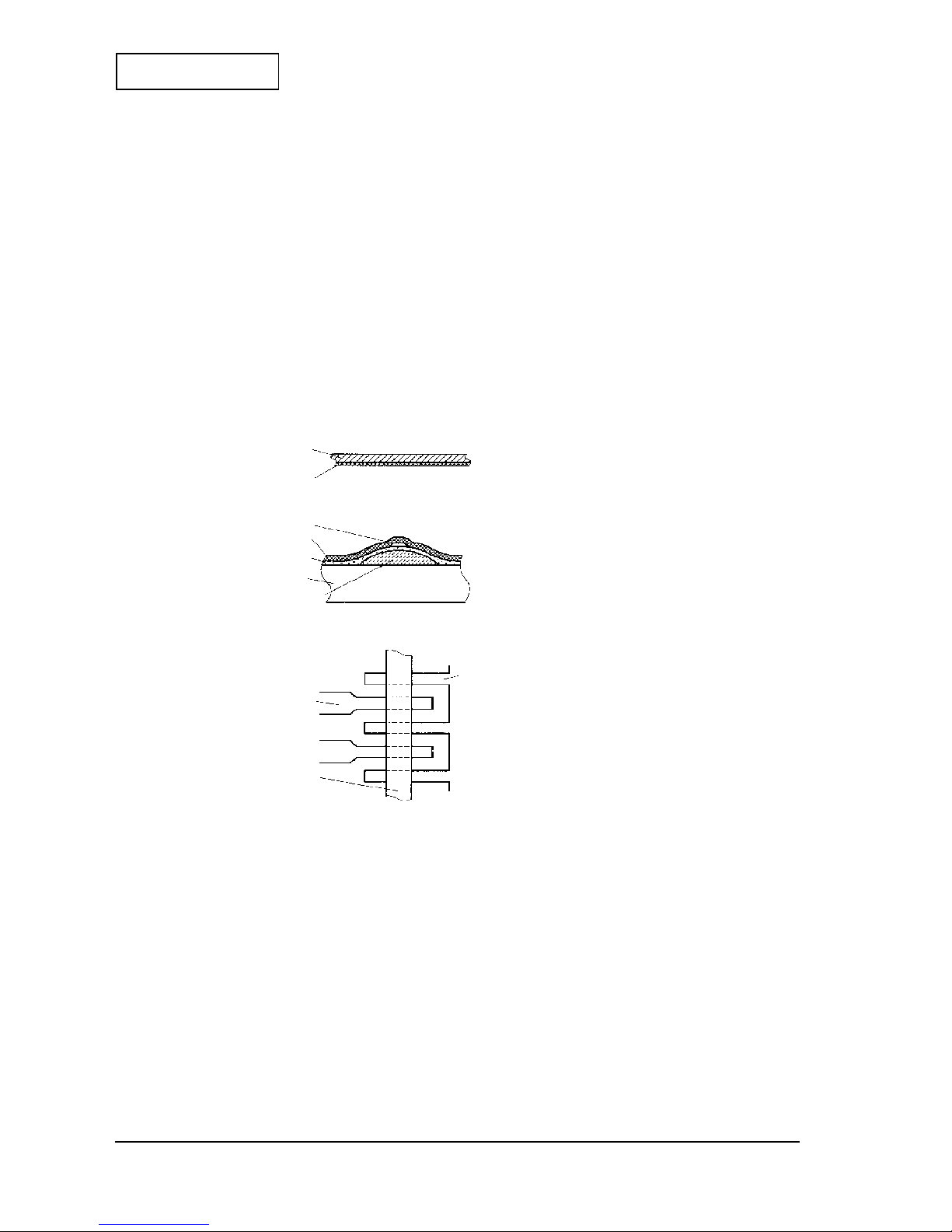
Printing operation principles
The cross-sections of the
thermal head
and the thermal paper are shown below. Printing is
performed in the following steps:
Figure 2-7 Cross -section of thermal head and thermal paper
1. Drive pulses are sent to the designated dot electrodes in accordance with the print signal.
2. Since the resistor layers are formed at the top of each electrode inside of the
thermal head
,
the resistor layers are heated up when the drive pulses are sent to the electrodes.
3. The thermal energy of the heated resistors is transferred via the protective layer of the
thermal head
to the surface of the thermal paper, and the heat-sensitive layer of the paper
changes color, thus forming the printed character.
<cross-section of thermal paper>
<cross-section of thermal head>
<top view of thermal head>
base
heat- sensitive layer
resistor layer
protective layer
electrode layer
ceramic base plate
glaze layer
electrode laye r
electrode laye r
resistor layer
Page 18
Rev. A Operation Principles 2-7
EU-T432 Technical Manual
Confidential
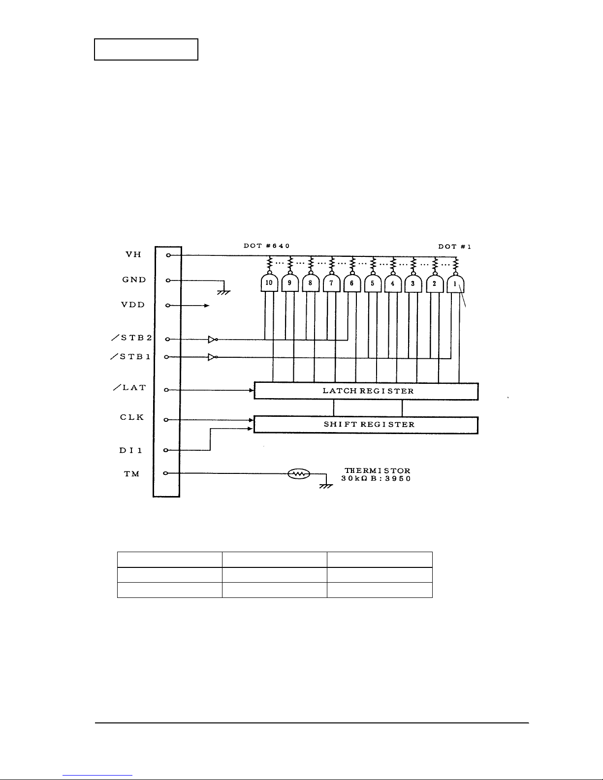
Data input and printing
The
thermal head
consists of the head heating elements, the head driver, which controls or
drives the head heating elements, and the
thermistor,
which detects the temperature of the
thermal head
. The serial print data input from Data In (DI1) is synchronized to the CLOCK
(CLK) input, and temporarily placed in the SHIFT REGISTER. Using the LATCH (/LAT) signal
timing, these data are then stored in the LATCH REGISTER. Activated by the STROBE signals
(/STR1, /STR2), the stored print data is used to control the gate ON condition for the head
heating element drive pulse.
This printer is equipped with two strobes, and can print using a maximum of four divisions.
The drive pulse width is controlled by the control circuit board module.
Figure 2-8 Thermal head block diagram
Table 2-3 Strobe and Dot Number
STROBE No. Dot No. Dots/STROBE
1 1 to 320 320
2 321 to 640 320
*The STB terminals are pulled down in the con trol IC.
64 output each
Page 19
2-8 Operation Principles Rev. A
Confidential
Paper Guide Mechanism
This mechanism consists of the paper guide mechanism. The paper path consists of the
paper
guide, straight, front
and the
paper guide, straight, back
. The paper path is shown below.
Figure 2-9 Paper path
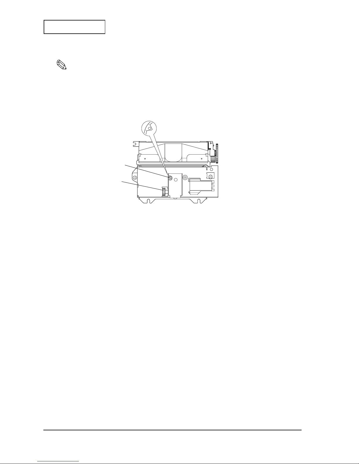
Detector Mechanism
This mechanism consists of the paper-end mechanism, the platen-open detector mechanism, the
head temperature detector mechanism, and the black mark detector mechanism.
Paper-end detector mechanism
The paper-end detector mechanism is located inside the paper guide mechanism to detect the
end of the thermal paper and the paper insertion state in the semi-autoloading mode. This
mechanism consists of the
transparent photo sensor
, the
lever, paper detector
which
presses against the thermal paper and the
spring, paper detector
which pulls the
lever,
paper detector
.
Figure 2-10 Paper -end detector circuit
paper guide, straight, back
paper guide, straight, front
platen
paper
<printer side>
paper-end detector signal
Photo interrupter
Pin No.
220
Ω
75 K
Ω
13 V
13
V
DD
11
7, 8, 10
GND
Page 20
Rev. A Operation Principles 2-9
EU-T432 Technical Manual
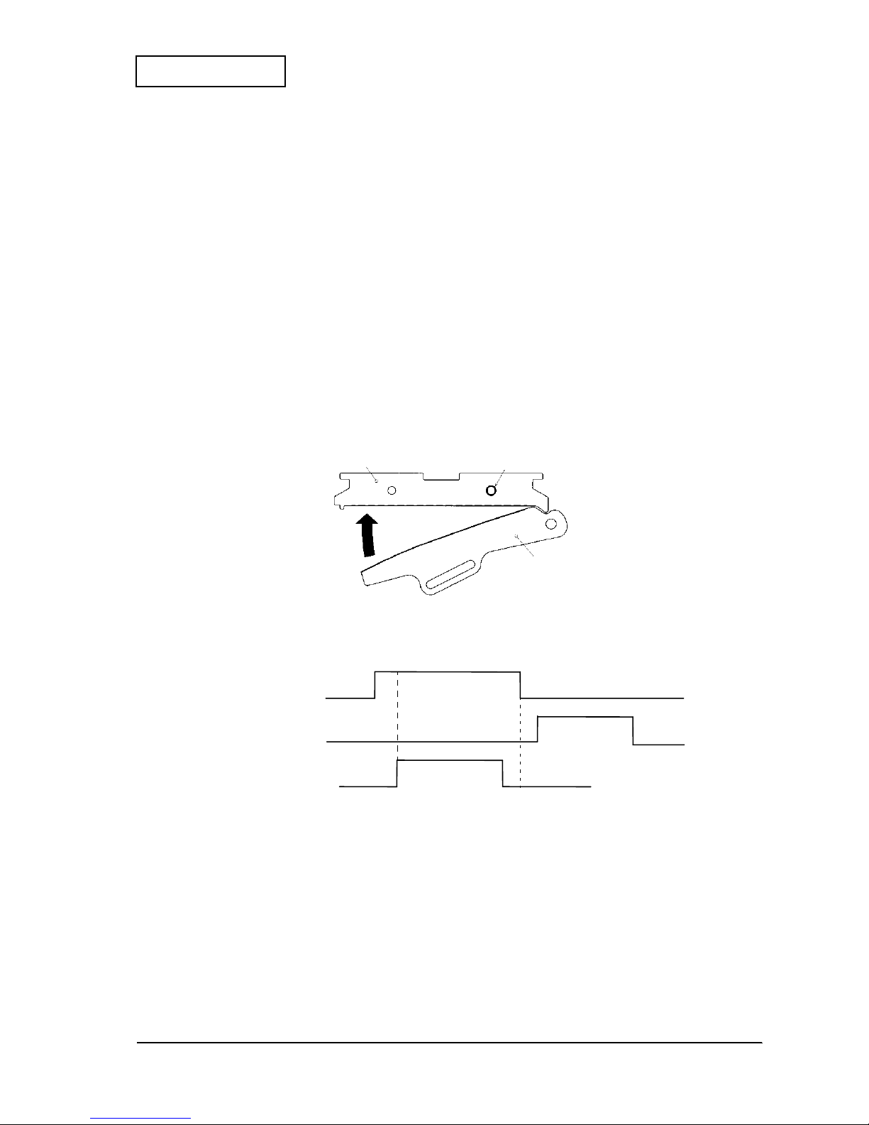
Confidential
The
transparent photo
sensor is in a high state (HI) when the paper is present, and in a low
state (LOW) when the paper is not present because the
lever, paper detector
blocks light to
the sensor. When the end of the thermal paper passes through the paper guide, the
lever, paper
detector
operates as shown in Figure 2-11. At this time, the output level from the
transparent
photo sensor
varies as shown in Figure 2-12, then the absence of paper is detected. When the
semi-autoloading function is used, the insertion of paper changes the status from “no paper” to
“paper.” Since the output level changes from LOW to HI , the status changes to “paper”; th en the
semi-autoloading function is in itiated.
Figure 2-11 Paper-end detector mechanism
Figure 2-12 Paper-end detector operation
platen
thermal head
transparent photo
sensor
lever, paper detector
paper guide, straight, front
frame, base
paper
<paper-present condit ion >
<paper-absent cond it io n>
paper guide, straight, back
paper-end signal
conductive confirma tion
paper-end detection
Page 21
2-10 Operation Principles Rev. A
Confidential
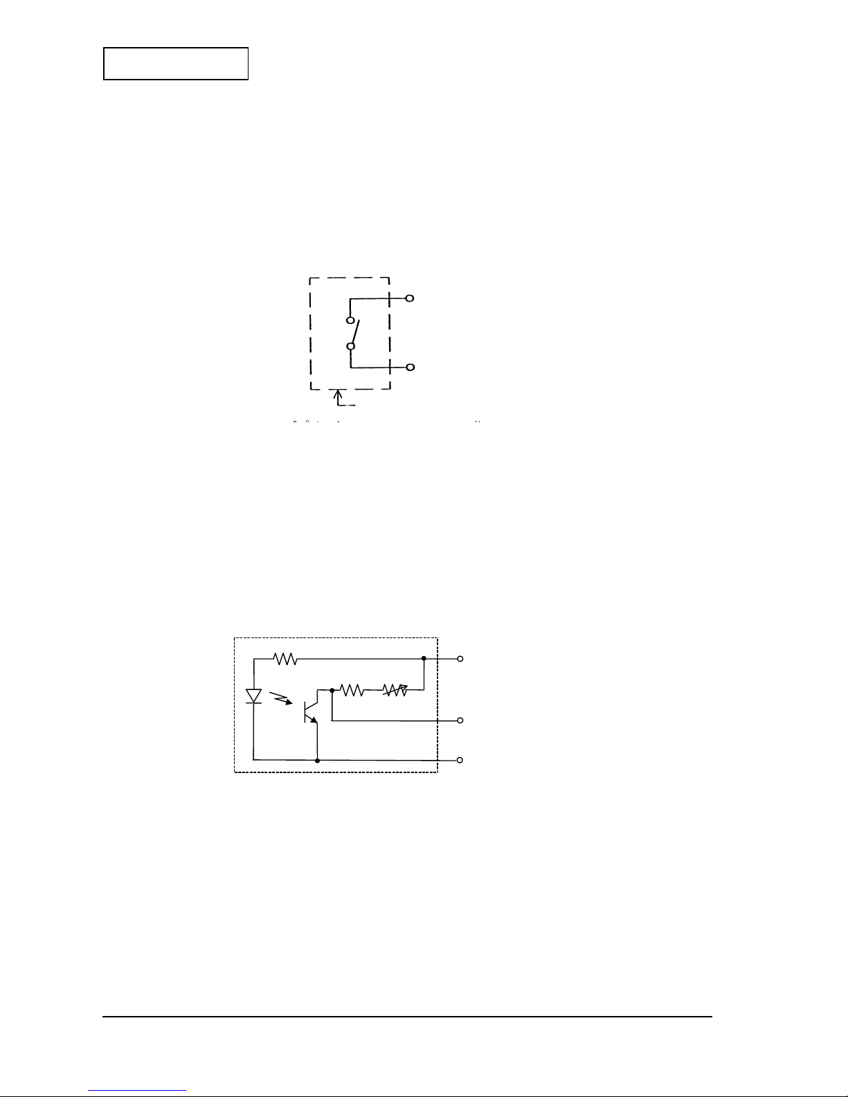
Platen-open detector mechanism
The platen-open detector mechanism has a
microswitch
which detects whether the
platen
is
open (printing impossible because the
thermal head
is away from the
platen
) or closed
(printing possible). The
microswitch
can be OFF only when the
frame, platen
is perfectly
closed, and at all other times is ON.
Figure 2-13 Platen-open detector circuit
Head temperature detector mechanism
The
thermal head
has a
thermistor
to detect the temperature of the
thermal head
.
Black mark detector mechanism
The black mark mechanism is a device whi ch can be at tached insi de the paper g uide mechanism
to determine the printing position when using pre-p ri nted ther mal pap er. Th is mec hani sm uses
the reflective photo sensor.
Figure 2-14 Black mark detector circuit
<printer side> Pin No.
platen open
platen open
Pins 14 and 15 can be reversed.
14
15
SW2
SW1
Pin No.
black mark de tector
output
<printer side>
220
Ω
0 to 100 K
Ω
10 K
Ω
13
V
DD
12
7, 8, 10
GND
Page 22
Rev. A Operation Principles 2-11
EU-T432 Technical Manual
Confidential
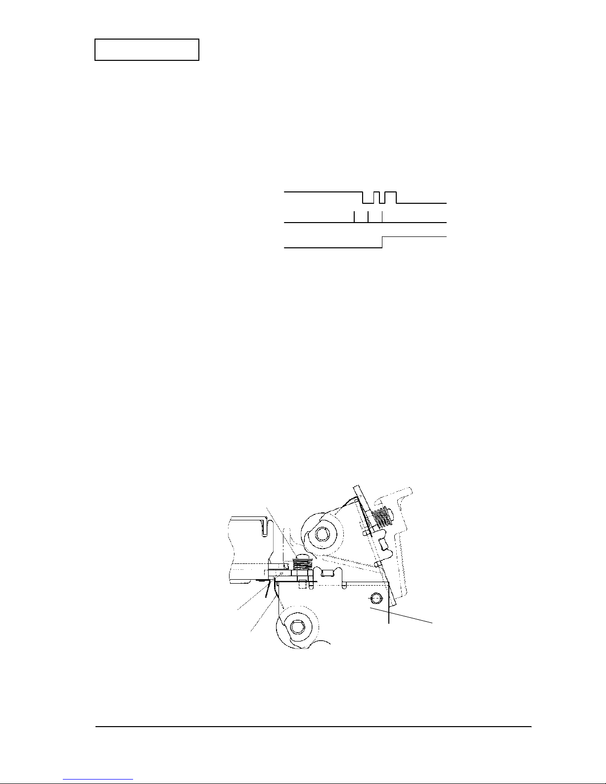
Black marks are detected through changes in output level from the reflective photo sensor. The
changes in reflectivity between the pre-printed black marks and blank areas of the thermal
paper cause the amount of light returning to the sensor to vary; then the sensor output level is
also varied as shown in Fig ure 2-15 . These v ariat ions ar e used t o detec t the black mark. Si nce the
relationship between the black mark an d the pri nt positi on can be specified in the pr inter set up,
detecting the black mark permits the correct positioning of the paper.
Figure 2-15 Black mark detecting operation
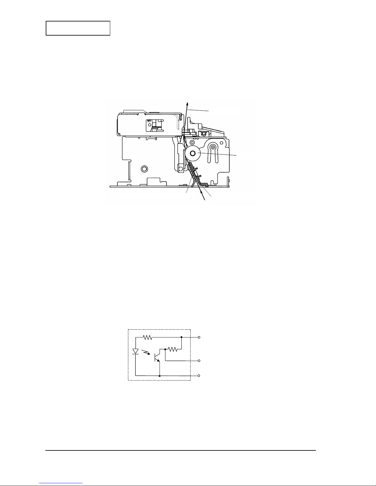
Autocutter Mechanism
This mechanism consists of the fixed blade mechanism, the movable cutter blade mechanism
and the emergency cutter mechanism.
The basic principl e of t he aut ocutt er mecha nism is an appl icati on of the sci ssors princi ple, where
the paper is cut by two crossi ng blades. A config urati on which al lows the two blades to separate
has been adopted so that the
fixed blade
separates from the
movable cutter bl ade , full
when
the
platen
is open.
Fixed blade mechanism
This mechanism is mounted on the frame platen unit. This configuration consists of the
fixed
blade
which cuts the paper directly, the
spring, fixed blade
which stabilizes the vertical
positioning of the
fixed blade
, and the
cover, fixed blade
which covers the
fixed blade
and
is a paper guide as well as makes the operation to open the
platen
safe.
Figure 2-16 Fixed blade mechanism
black mark de tector signal
conductive confirmation
black mark detection
spring, fixed blade
fixed blade
cover, fixed blade
frame, platen unit
Page 23
2-12 Operation Principles Rev. A
Confidential
Movable cutter blade m ec h an ism
This mechanism is mounted on the
frame, base
.
The drive force tr ansmission mec hanism is on the
cover, cutter
side. The
motor, cutter
is a DC
brush motor on the
gear, cutter motor
. It supplies the power and is attached on the
cover,
cutter
with screws. The
gear, reduction A/C
and the
gear, cutter worm
are supported by t he
shaft, reduct i o n A/C
, and the
gear, cutter drive
is attached with push nuts to the
shaft,
cutter drive gear
fixed on the
cover, cutter
.
After being transmitted through the
gear, reduction A/C
and the
gear, cutter worm
, the
power is transmitted to the
gear, cutter drive
. The
gear, reduction A/C
is pushed against the
gear, cutter w o r m
by the
spring, cutter clutch
and the
washer, Clutch
, forming a one-way
clutch which is used to cut off the transmission of power when the transmitted load exceeds a
prescribed level during paper cuttin g.
The rotational movement of the
gear, cutter drive
is transmit ted to the back and forth
movement of the
movable cutter blade
by being engaged with the
shaft, movable cutter
blade drive
with the oval hole of the
movable blade
on the
frame, cutter
. Also, the
microswitch
attached to the
cover, cutter
is connected t o th e
gear, cutter drive
, enabling it to
detect the position of the
movable cutter blade
. The lead wires of the
motor, cutter
and the
microswitch
are bound together and connect to the
circuit board
.
The
shaft, movable cutter blade
is on the
frame, cutter
side. The
receiver, movabl e cutter
blade
, the
spacer, movable cutter blade
, the
spring, movable cutter blade
and the
washer, movable cutter blade spring
are mounted on the
shaft, movable cutter blade
in a
group with a push nut.
When putting the
cover, cutter
and the
frame, cutter
together, engage the
shaft, movable
cutter blade drive
with the oval hole of the
movable cutter blade
, and secure the
cover,
cutter
and the
frame, cutter
with screws.
Figure 2-17 Movable cutter blade mechanism
gear, cutter drive
shaft, cutter drive gear
cover, cutter
shaft, movable cutter
blade drive
gear, cutter worm
shaft, reduction A/C
(inside the gear, cutter
worm: dot lined part)
frame, cut ter
movable cut ter blade , full
receiver, movable
cutter blade
spring, movable
cutter blade
washer, movable
cutter blade spring
shaft, movable cutter blade
spacer, movable cutter blade
motor, cutter
microswitch
gear, cutter motor
Page 24
Rev. A Operation Principles 2-13
EU-T432 Technical Manual
Confidential
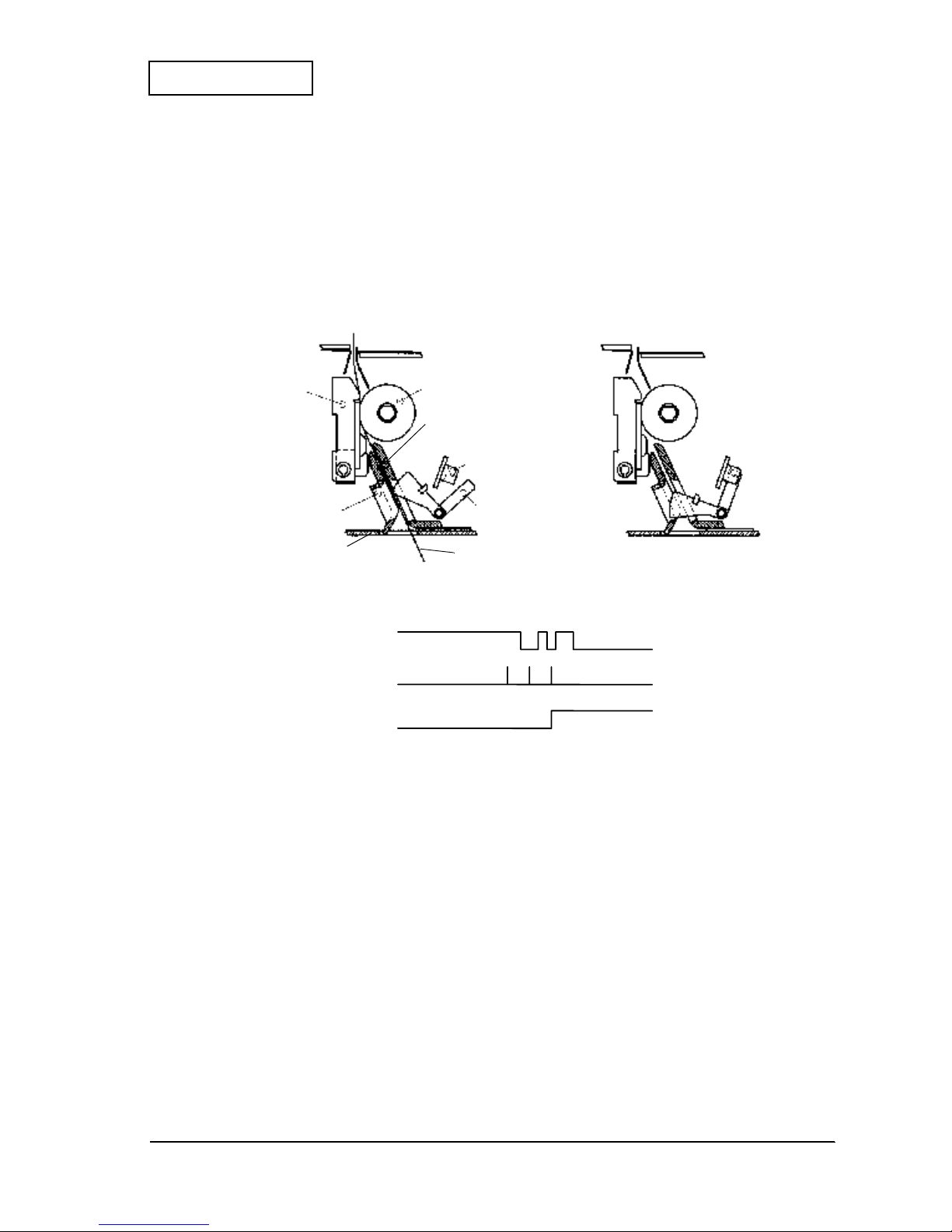
Autocutting operation
The
autocutter
will operate when the frame platen unit is closed and a paper is loaded. (The
frame platen unit c an be c losed when t he
movable cutter blade, full
is in the standby position.
The autocutting operation is performed in the following steps:
1. Drive the
motor, cutter
in the forward rotation.
2. The
microswitch
is switched from OFF (open) to ON (closed) while the
motor, cutter
continues to rotate in the forward rotation. The
movable cutter blade, full
intersects with
the
fixed cutter blade
and cuts the paper from the ri ght t o t he l eft, toward t he fi rst co lumn.
3. After cutting the paper, the
movable cutter blade, full
starts to return to the home
position.
4. As the
movable cutter blade, full
approaches the home position, the
microswitch
is
switched from ON (closed) to OFF (open); then the
motor, cutter
stops rotating and the
brake is applied.
Figure 2-18 Auto cutting operation
Figure 2-19 Auto cutting control example
fixed blade
spring, fix e d blade
movable cut ter blade , full
cutter motor forward driving
cutter motor brake
switch signal rectifying
waveform
Page 25
2-14 Operation Principles Rev. A
Confidential
Note:
If the
movable cutter blade, full
cannot be returned to the home position because of foreign matter
locking the blade when powered by the
motor
, rotate the knob on the
gear, cutter worm
with a tool
such as a ball-point pen or tweezers to move the
movable cutter blade, full
to the home position. The
window on the
cover, cutter
can be used to check if the
movable cutter blade, full
has returned to
the home position.
Figure 2-20 Home position check
window
<Movable cutter blade in the home position>
knob
Page 26

Rev. A Operation Principles 2-15
EU-T432 Technical Manual
Confidential
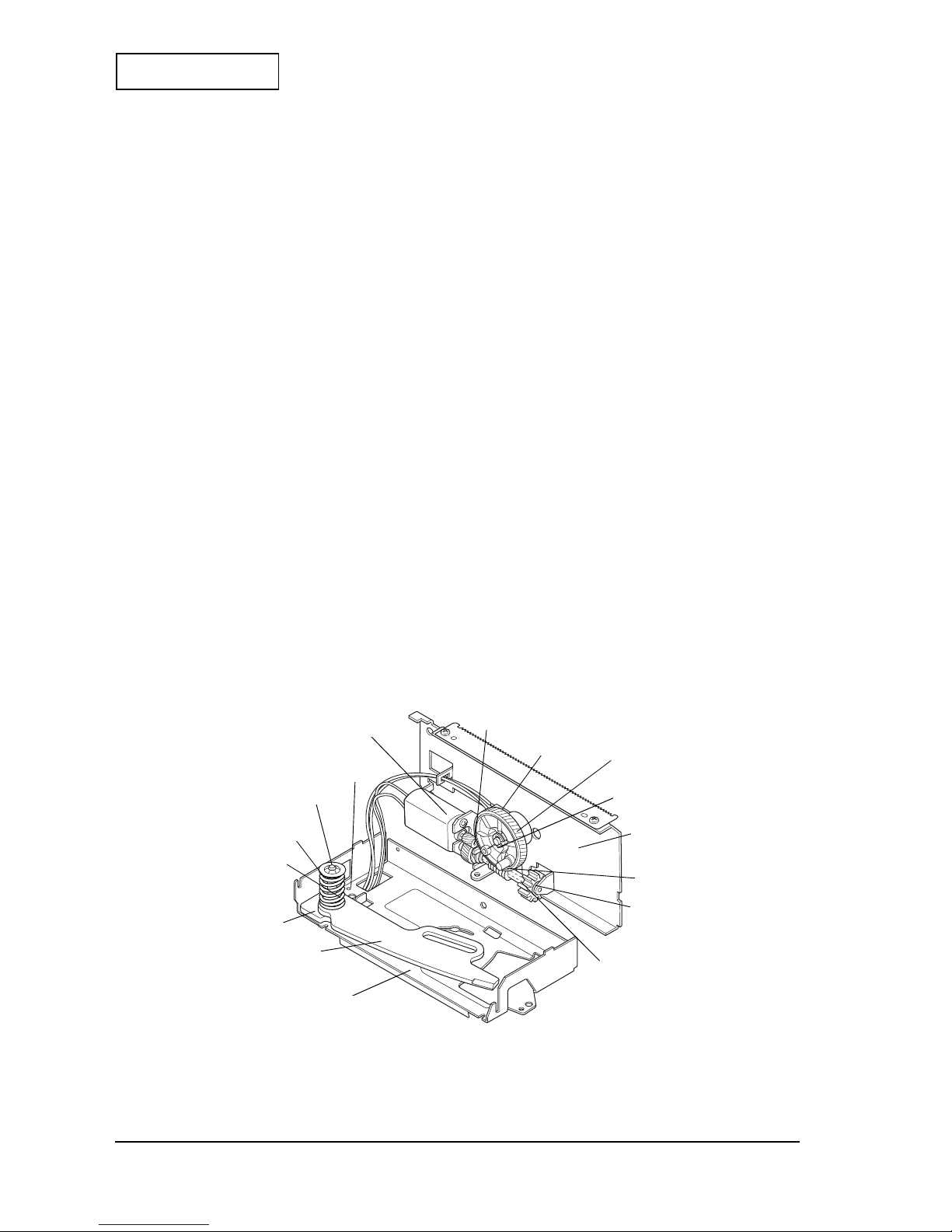
Cut Sheet Presenter Module
The cut sheet presenter module has a mechanism to feed the paper printed and cut by the
printer mod ule to the paper exit.
Figure 2-21 Appearance of cut sheet presenter module
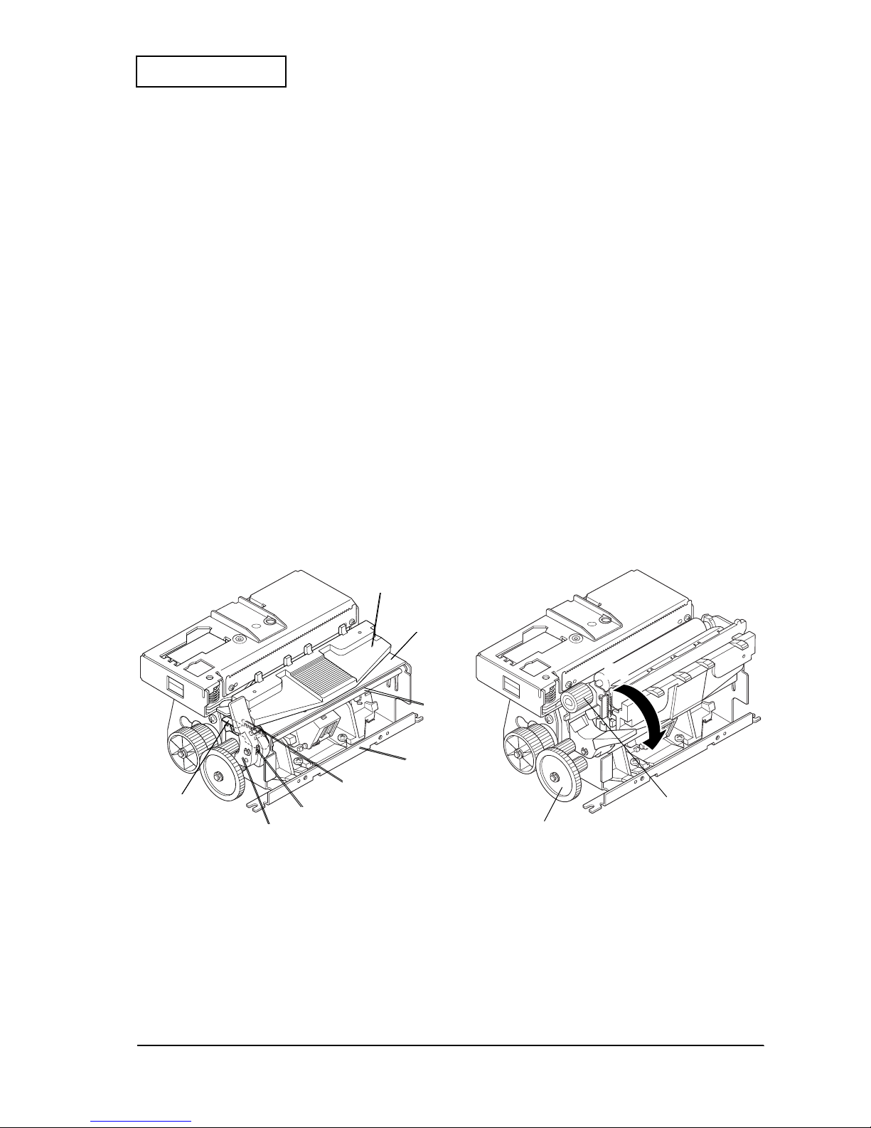
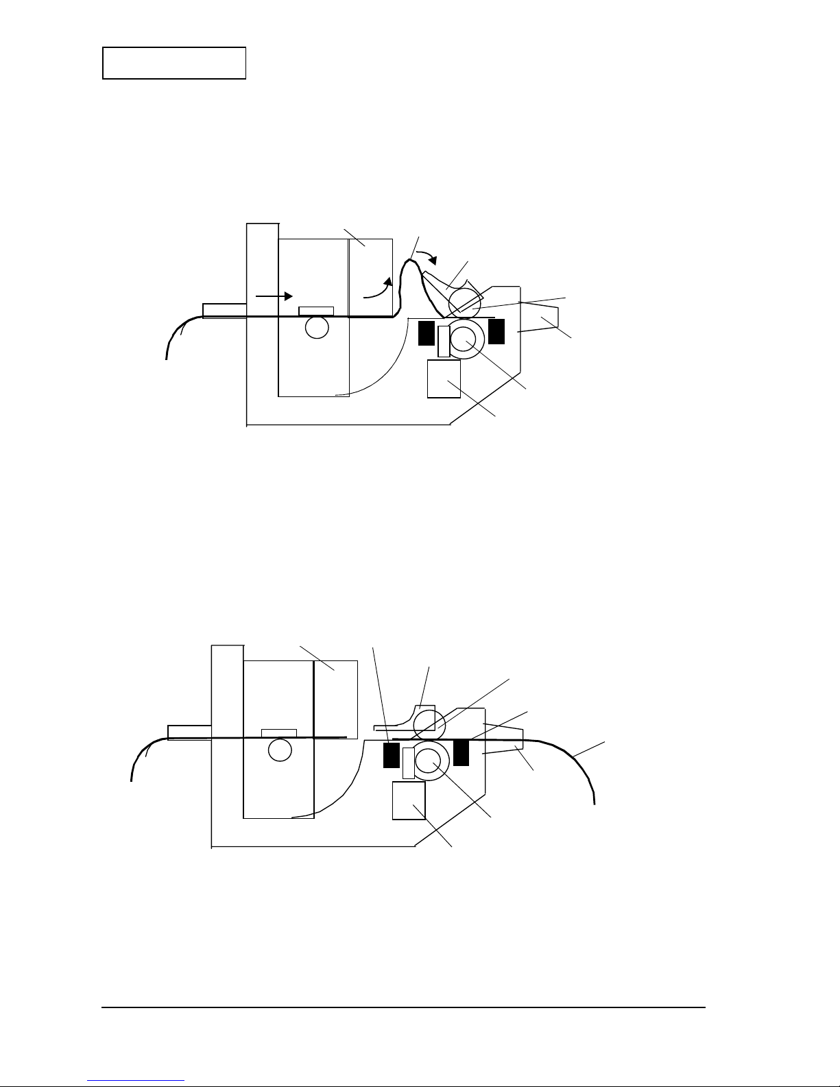
Paper Feeding Operation (With a Loop)
A paper feeding operation is performed at the same time with the start of the paper feeding of
the printer module. The
motor, cutting paper feed
rotates in the clockwise direction as seen
from the shaft direction, and the
roller, presenter
rotates in the clockwise direction via the
gears. The
roller, cutting paper hold
is pressed to the
roller, presenter
by a spring.
The paper sent from the print er mod ule i s fed along the p aper guidin g par t, and fe d be tween t he
roller, presente r
and the
roller, cutting paper hold
. When the tip of the paper reaches the
detection position of the
paper presence sensor
, the
motor, cutting paper feed
stops
temporarily.
Figure 2-22 Start of the cut sheet feeding
roller, cutting paper hold
paper eject sensor
roller, presenter
paper presence sensor
motor, cutting paper feed
autocutter
paper exit
Page 27
2-16 Operation Principles Rev. A
Confidential
While the tip of the paper sent from the printer module is in the standby state between the
roller,
presenter
and the
roller, cutting paper hold
, the paper is continuously fed from the printer
module. The paper pushes up the
paper guide, upper
and temporarily forms a loop.
Figure 2-23 Cut Sheet with Loop
When the paper feed from the printer module is finished, the cutter on the printer module cuts
the paper; then the
motor, cutting paper feed
resumes rotating and the cut sheet is fed from
the
roller, presenter
to the
paper exit
.
When the
paper eject sensor
detects the end of the cut sheet, the
motor, cutting paper feed
stops. With the cut sheet between the
roller, presente r
and the
roller, cutting paper hold
, a
series of operations is completed and the cut sheet is ejected from the
paper exit
.
A
paper presence sensor
can detect whether or not the cut paper is removed.
Figure 2-24 End of the Cut Sheet Feeding Operation
motor, cutt in g pa p er feed
roller, presenter
paper guide, upper
roller, cutting paper hold
loop
autocutter
paper exit
autocutter
paper guide, upper
roller, cutting paper hold
paper exit
roller, presenter
cut sheet
paper eject sensor
motor, cutting pape r feed
paper presence sensor
Page 28
Rev. A Operation Principles 2-17
EU-T432 Technical Manual
Confidential
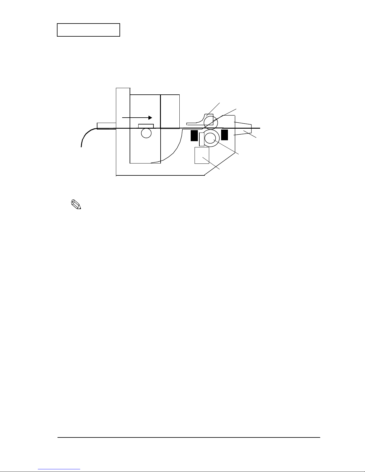
Paper Feeding Operation (Without a Loop)
The cut sheet presenter module can feed paper without forming a loop.
Figure 2-25 Cut Sheet Operation without Loop
Note:
During paper feeding operations without a loop, do not pull out the paper.
Detector Mechanism
The detector mechanism consists of the
presenter open sensor
, the
paper eject sensor
, and
the
cut sheet presence sensor
.
Presenter open se n sor
This sensor detects whether the
cut sheet presenter module
is open or not.
Paper eject sen s or
This sensor detects the paper presence in the paper feeding route.
Cut sheet presence sensor
This sensor detects whether or not the cut sheet has been removed.
roller, cutting paper hold
motor, cutting paper feed
roller, presenter
paper exit
paper guide, upper
Page 29
2-18 Operation Principles Rev. A
Confidential
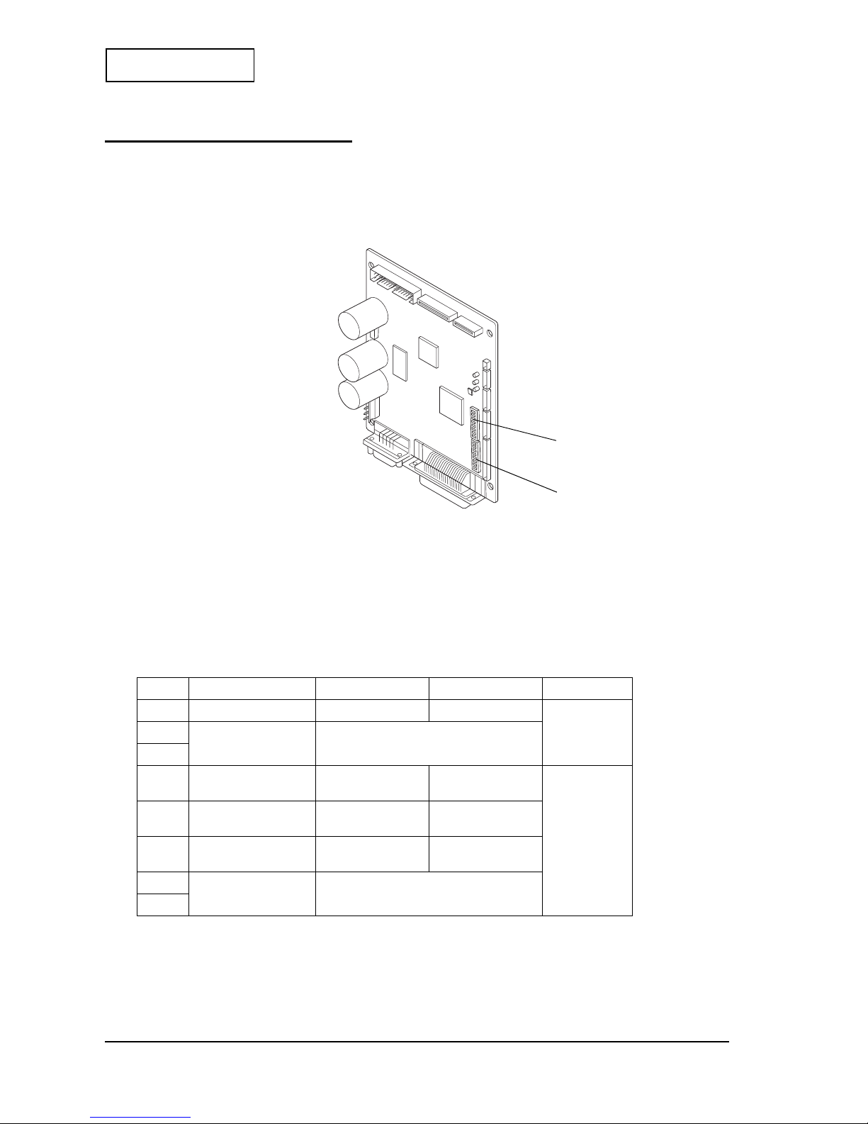
Control Circuit Board Module
The control circuit board module controls all functions of each module and has the interface
connectors and the power supply terminals. Each function can be set by using the DIP switches
and the memory switches.
Figure 2-26 Appearance of the control circuit board module
DIP Switches
The circuit board has two DIP switches (DSW 1/2). Each setting is as follows:
DIP Switch 1
*: Effective only when the serial interface is selected .
Table 2-1 DSW 1
SW No. Function
ON OFF
Default Setting
1 Black mark dete c ot o r Enable d Disabled
OFF
2
Interface selection
Refer to Table 2-2
3
4 Serial interface
handshaking
XON/XOFF DTR/DSR or
CTS/RTS
OFF*
5 Serial interface parity
check
Yes No
6 Serial interface parity
selection
Even Odd
7
Serial interface baud
rate selection
Refer to Table 2-3
8
DIP switch 1
DIP switch 2
Page 30

Rev. A Operation Principles 2-19
EU-T432 Technical Manual
Confidential
bps: bits per second
DIP Switch 2
(*1): Fixed to OFF
(*2): Effective only w he n th e s eria l in terface is selected.
Table 2-2 Interface Selection
Interface
Switch No. 2 Switch No.3
Parallel interface (IEEE1284) OFF OFF
Serial interface (RS232) OFF ON
Optional interface ON ON or OFF
Table 2-3 Baud Rate Selection
Transmission speed (bps) Switch No.7 Switch No.8
4800 ON ON
9600 OFF ON
19200 ON OFF
38400 OFF OFF
Table 2-4 DSW 2
SW No. Function
ON OFF
Default setting
1
Model type selection Refer to Table 2-5
ON
2
OFF
3
Print density selec tio n
Refer to Table 2-6
4
5 Operation mode
selection
Refer to Table 2-7
6Factory use OFF (*1)
7 I/F pin 6 reset signal-1
Enabled
Disabled
OFF (*2)
8 I/F pin 6 reset signal-2
Enabled
Disabled
Table 2-5 Model Type Selection
Model Switch No.1 Switch No.2
79.5 mm {3.15"} paper-width model: 576 dots) ON OFF
Page 31

2-20 Operation Principles Rev. A
Confidential
Notes:
•
Changes in DIP switch set t in gs (e x clud ing switches 2-7 and 2-8 ,i nt erface reset signals) are recog n ize d on ly
when the printer power is turned on or when the printer is reset by using the interfa c e.
•
If you turn on DIP SWs 2-7 and 2-8 while the printer power is turned on, the printer may be reset, depen di ng on
the signal state. DIP switches should not be changed while the printer power is on.
Memory Switches
Other settings except DIP switches 1 and 2 are set by the memory switches. (The settings are
changed with a GS (
GS (GS (
GS ( EEEE command, and also can be changed by using the MEMSW.exe included
with EPSON Advanced Windows Drivers.) The settings of the memory switches are as follows:
(*1): Effective only in th e s eria l in terface model.
(*2): Effective only in the parallel interface model.
Table 2-6 Print Density Selection
Level Print Density Switch No.3 Switch No.4
1
Slightly light
ON ON
2
Normal
OFF OFF
3
Slightly dark
ON OFF
4
Dark
OFF ON
Table 2-7 Operation Mode Selection
Operation mode Switch No.5
Hexadecimal dump ON
Normal
OFF
Table 2-8 Memory Switch 1
SW No. Function
ON (1) OFF (0)
Default setting
1
Reserved
Fixed to OFF OFF(0)
2
3 BUSY condition Receive buffer full Receive buffer full
or offline
OFF(0)
4 Receive error Ignored Prints “?” OFF(0) (*1)
5 Auto line feed Always enabled Always disabled OFF(0) (*2)
6 to 8 Reserve d
Fixed to OFF OFF(0)
Table 2-9 Memory Switches 2 to 5
SW No. Function
ON (1) OFF (0)
Default setting
1 to 8
Reserved
Fixed to OFF OFF(0)
Page 32

Rev. A Operation Principles 2-21
EU-T432 Technical Manual
Confidential
(*1): This setting is used for selecting the following modes:
<Power consumption has priorit y over prin t spee d >
In this mode, the printer operates with power consumption as low as possible.
<Print speed has priority over power consumption>
In this mode, the printer prin t s at the max i mu m s peed.
If the printer power is supplied with a power source that is less than 100 W, do not turn on the print speed mode.
(*2): This setting sp ec ifi e s th e pr in ter’s operation if a paper out is de tected during printi ng an d f eed in g .
Enabled: Ejects paper automatically
Disabled: Does not eject paper (from the presenter)
(*3): The print energ y is applied according to th e ta bl e below.
The values in the table below are relative ones,a ssum in g tha t the print ener gy for normal paper with normal
density is 100 %.
Table 2-10 Memory Switches 6
SW No. Function
ON OFF
Default setting
1 to 2
Reserved
Fixed to OFF OFF(0)
3
Print speed control
Speed has priority
over power
consumption
Power consumption
has priority over
print speed
OFF (0) (*1)
4
Auto eject if the
paper out is
detected
Disabled En ab led OFF (0) (*2)
5
Reserved
Fixed to OFF OFF (0)
6
Selection of type of
thermal paper
Excellent
preservation paper
(thick type)
Normal OFF (0) (*3)
7
Reserved
Fixed to OFF OFF (0)
8
Selection of the
operation of
GS FF
Disabled Enabled OFF (0)
Table 2-10-1 Print Density Selection
Memory SW6-6
ON OFF
Slightly light
100% 85%
Normal
115% 100%
Slightly dark
130% 115%
Dark
145% 130%
Page 33

2-22 Operation Principles Rev. A
Confidential
(*1): • Effective only for the model type with the paper roll supply module
• This setting lets the printer tell the paper near-end by sending the secondary paper near-end status when the
specified length of paper is fed after the pri mary paper near-e nd s ensor in the paper ro ll supply module
detects the paper near-end.
• If the paper near-end sensor 2 is installed in the printer, the detecting result of the paper near-en d sensor 2
becomes the secondary near-end status. (The setting of memory switches 7-2 and 7-3 are ignored.)
(*2): Effective only when using with the cut sheet presenter module .
Table 2-11 Memory Switch 7
SW No. Function
ON (1) OFF (0)
Default setting
1
Reserved
Fixed to OFF OFF(0)
2 and 3
Setting for the
secondary paper
near-end position
Refer to Table 2-12
OFF(0) (*1)
4 Operation after
cutting
Ejects fully Clamps
OFF(0) (*2)
5 Paper initializing
operation when the
power is turned on
Always cuts Detects paper’s tip
6 to 8 Reserve d
Fixed to OFF OFF(0)
Table 2-12 Setting for Paper Near-end Detecting Position
Paper length
(for the time between detecting the
primary paper near-end with the nearend sensor and sending the status of
the secondary paper near-end)
Memory SW No.7-2 Memory SW No.7-3
Approximately 5 m {196.85"}
OFF OFF
Approximately 10 m {393.70"}
ON OFF
Approximately 20 m {787.40"}
OFF ON
Approximately 30 m {1181.10"}
ON ON
Page 34

Rev. A Operation Principles 2-23
EU-T432 Technical Manual
Confidential
(*1): Do not set SW 3 to ON in the following condition:
•
The partial cutter is used when the cut sheet pre sent er mo d ule is not used .
When backward paper feeding is enab led , the follo win g pro cess is execut ed .
•
After cutting the paper with a
GS V
command, backward paper feeding is executed (when the Black
mark detector is disabled).
•
The print star ti ng position adju s tment with a
GS (F
command can be set to the backward direction
relative to the cutting position. In this case, the maximum backward correction value is 14 mm {0.55"}
(112 step × 0.125 mm {0.005"} per step).
(*2): Specific offline means the following states.
• Error state except an automatic recovery error state
• Platen open
• Cut sheet presenter module or cover open
• Paper empty
If this switch is turned on, the printer clears the receive buffer when the offline status shown above occurs. Then
the printer executes any real-time command (
DLE ENQ, DLE EOT
) if it is there, and discard s all ot h er da ta.
When the receive buffer is cleared, if this switch is turned on, three bytes of data, 37H, 24H, and 00H, are
transmitted.
×
: can be either setting
Table 2-13 Memory Switch 8
SW No. Function
ON (1) OFF (0)
Default setting
1 to 2
Print control mode
Refer to 2-14 OFF(0)
3 Backward paper
feeding
Enabled Disabled OFF(0) (*1)
4 Autocutter
installation
Not installed Installed OFF(0)
5 Specific offline
operation
Discards receive
data
Keeps receive data OFF(0) (*2)
6 Backward paper
feeding amount
88 steps 108 steps
OFF(0)7 Test print when the
paper is loaded
Enabled
Disabled
8Reserved
Fixed to OFF
Table 2-13 Print Control Mode Selection
Default for the print
control mode SW 1 SW 2
Non-divided energi zin g
mode
OFF OFF
Two-part energizing
mode
ON OFF
Four-pa rt energizing
mode
×
ON
Page 35

Rev. A Handling 3-1
EU-T432 Technical Manual
Confidential
Chapter 3
Handling
Precautions
Transport Precautions
❏ When shipping the printer, use antistatic packing materials.
❏ Remove the paper roll when transporting the EU-T432.
❏ Make sure to close the paper roll supply module, the
platen unit
of the printer mod ule, and
the cut sheet presenter module when transporting.
Carrying Precautions
❏ Hold the paper roll supply module and the handle (a part with a green sticker on it) on the
paper roll supply module when carrying the printer as shown below. When this product is
equipped with an optional
loop guide
, you can hold the loop guide to carry it.
Note:
Do not hold parts other than those mentioned above; otherwise you can cause damage or deformation
of parts that will affect the operation of the printer.
❏ When you put this unit on a place such as a desk, be sure to put it on a flat place; otherwise,
a malfunction may occur because of deformation of parts.
Figure 3-1 Correct way of holding the EU-T432
handle
cut sheet presenter module
printer module
paper roll supply module
hole for a ground wire
Page 36

3-2 Handling Rev. A
Confidential
Installation Precautions
❏ When installing the unit, firmly secure four mounting parts at the bottom of the paper roll
supply module to the system side with screws.
❏ Make sure to ground the unit by using the hole for a ground wire on the side of the frame.
(See Figure 3-1 for the position.)
Note:
If the system side where the unit is installed is not flat, that could cause deformation of parts and
malfunction. (It is recommended the difference in level is 0.3 mm {0.012"} or less.)
Handling Precautions
Paper roll supply module
❏ Do not apply excessive pressure to the
paper roll supply module
when opening or closing
it; otherwise, the unit may not open and close properly because of deformation of parts.
❏ Do not touch the light emission or receiving surfaces of the
paper NE detector
; otherwise
you may cause damage from dirt or static electricity.
Printer module
CAUTION:
Since the thermal head area and the motor surface can be hot during and right after
printing, never touch them with your bare hands; allow about 15 minutes for them to
cool.
❏ Since the EU-T432 contains permanent magnets (in the motor) as well as electromagnets,
they should not be used in an environment with excessive dirt, dust, or metallic dust.
❏ Never print without p ap er inst all ed or wi t h t he head away from the
platen
, because the life
of the
thermal head
may be shortened.
❏ Never pull out the paper (forward or backward) with the head down (against the
platen
).
❏ Do not turn off the power during operations, especially during a cutting operation;
otherwise the cutter blade could be exposed, leaving the
platen un i t
difficult to open.
❏ Since the head heating elements and the driver IC are very delicate, avoid touching them
with any metal objects such as tweezers or screwdrivers.
❏ Open the
platen unit
only when required.
❏ Never touch the surface o f the head heating elements or t he d ri v er IC beca use d irt ma y stic k
to them, affecting the head heating elements or causing damage from static electricity.
❏ Before handling the
thermal head
, use proper body grounding procedures to avoid
damage from static electricity.
Page 37

Rev. A Handling 3-3
EU-T432 Technical Manual
Confidential
❏ Make sure no dust collects on the thermal paper.
❏ Since the printer uses a line thermal print head, condensation must be avoided. If
condensation occurs, do not turn on the printer until it has disappeared.
❏ Do not apply excessive pressure to the
lever, platen
when opening or closing the
platen
unit
with the lever.
Cut sheet presenter module
CAUTION:
Since the paper feed motor surface will be hot after printing for a long period of time,
never touch them with your bare hands; allow about 15 minutes for them to cool.
❏ Since the EU-T432 contains permanent magnets as well as electro magnet s in the motor, they
should not be used in an environment with excessive dirt, dust and metallic dust.
❏ Operate the cut sheet presenter module only when required. Do not apply excessive
pressure when operating the cut sheet presenter module.
❏ Do not turn off the power during operations because that could cause a paper jam.
Control circuit board module
The serial interface is secured with inch-type hexagonal lock screws. If you need to use
millimeter-type screws, replace the inch-type screws with the millimeter-type screws enclosed
in the box.
Paper roll
❏ Use only the recommended thermal paper because thermal paper contains a high ion
content such as Na, K and Cl may damage the head heating elements.
❏ Avoid heat, humidity, sunlight and solvents, regardless of whether or not the paper has
been used. (Thermal paper gradually darkens at about 70°C {158°F}.)
❏ Remove the installed paper roll when the unit is not used for a long time in a high
temperature or high humidity condition; otherwise the thermal sensitive materials
contained in the thermal paper may stick to the thermal head area, affecting the printing
quality.
❏ Label sheets are not available for the EU-T432.
Page 38

3-4 Handling Rev. A
Confidential
Storage Precautions
❏ Do not store the printer in environments with excessive dust, high temperature, high
humidity, or in direct sunlight.
❏ Before storing the EU-T432 for an extended time, remove the paper and wipe off dirt and
dust; then clean parts such as the
platen
and the
thermal head
of the printer module with
alcohol. After the alcohol evaporates, close each module and store the unit.
Note:
If you leave the printer with the paper installed, discoloration of the paper and stickiness between the
paper and the
platen
may occur. In this case, replace the paper.
❏ Storing the printer for an extended period with the
platen
closed could cause the platen
rubber to deform and result in defective printing. If the platen rubber is deformed, it can be
restored to its proper shape by feeding paper through the printer. Just feed paper through
the printer until the
platen
works properly; then resume printing.
Opening and Closing Modules, Unit and Part
Follow the steps below to open and close modules, unit, and part you want. See Figure 3-2 on
page 3-5.
Note:
❏
Do not apply excessive pressure to any operational part; otherwise its function may be damaged
because of deformation or damage of the part.
❏ Apply pressure to each operational part only in the specified direction; otherwise its function may be
damaged because of damage or deformation of the part.
Paper Roll Supply Module
Note:
When opening or closing the paper roll supply module, make sure to secure the bottom of the module.
1. While holding down the
frame open lev er
to unlock the paper roll supply module, pull the
plate, opening an d shutti ng
or the optional
loop guide
to the near side (in the direction
of arrow A) and turn the paper roll supply module to open it.
2. To close the module, push it back in the opposite direction of arrow A until it stops. At this
time, make sure that the
frame open lever
is securely engaged with the fixing part. (Make
sure the module is not open when it is pulled in the direction of arrow A.)
Platen Unit
1. To open the unit, hold down the
lever, platen
(green lever) of the printer module.
2. To close the unit, turn the
lever, platen
upward.
Page 39

Rev. A Handling 3-5
EU-T432 Technical Manual
Confidential
Cut Sheet Presenter Module
1. Put your fingers on the top and bottom of the cut sheet presenter module; then pull the
module up at an angle (in the direction of arrow B) to slide it.
2. Pull the module until the mounting dowels on both sides of the module are disengaged;
then turn the module downward and open it.
3. To close the module, lift up the bottom of the
paper exit
and slide it back to the original
position. At th is time, make su re that the mount ing dowels (on both sides) are securely
engaged with the mounting parts on the cut sheet presenter module.
Paper guide, upper
To open the
paper guide, upper
, lift up the knob on the right edge of the paper guide.
Figure 3-2 Opening/closing units and module
plate, opening and shutting
paper guide, upper
paper roll supply modu le
lever, platen
cut sheet presenter module
mounting dowels
Opening andClosing of
the platen unit
Opening/ Closing of
the paper roll supply module
tab
A
B
paper exit
Opening/ Closing
of the cut sheet
presenter module
Opening/ Closing of
the paper guide, upper
frame, open lever
Page 40

3-6 Handling Rev. A
Confidential
Loading and Removing a Paper ro l l
Loading a Paper roll
Follow the steps below to load or remove the paper roll. See Figure 3-3 on page 3-7.
Note:
Use only the paper specified in the EU-T432 specifications issued by Seiko E pson Corporation.
Loading paper for the paper roll supply module
1. Open the paper roll supply module. (See “Opening and Closing Modules and Other Parts”
on page 3-4.)
2. Remove the
shaft, roll paper holder
from the
roll paper holder
. (Since there are two
springs on the right and left sides of the shaft to keep it from being accidentally removed,
pull the shaft toward the groove on the paper holder to remove it.)
3. Attach a
holder, roll paper
which meets the inside diameter of the paper core to the
shaft,
roll paper
; then secure it with a C-ring.
Note:
At the default setting, the
holder, roll paper A
(for the 25.4 mm {1"}) inner diameter p aper co re) is
attached to the paper roll supply module. Since other holders are available as optional parts, use the
holder, roll paper
that meets your paper core size. The
holder, roll paper B
is for a 50.8 mm
{2"} inner diameter paper core, and the
holder, paper roll C
is for a 76.2 mm {3"} inner diameter
paper core.
4. Load the paper roll to th e
holder, roll paper
until it stops against the flange of the holder.
5. Facing the printing surface upwards, install the
holder, roll paper
to the
roll paper
holder
. After installing, make sure that the paper roll is secured by the two springs on both
sides.
Note:
Make sure that the paper roll is loaded with the printing surface facing upwards.
Page 41

Rev. A Handling 3-7
EU-T432 Technical Manual
Confidential
6. Turn the paper roll supply module back to its original position until it is locked by the
frame open lever
with a click sound. Then turn it back so that the
plate, paper guide
is
not deformed.
Figure 3-3 Loading and removing the paper roll
holder, roll paper
shaft, roll paper
roll paper
holeder
paper roll supply modu le
C-ring
panel switches
plate, paper guide
Page 42

3-8 Handling Rev. A
Confidential
Loading paper for printer module
Follow the steps below to load the paper for the printer module from the paper roll supply
module.
1. Cut the edge of the paper as shown below.
Figure 3-4 Shape of paper edge
2. Pull out a certain amount of paper.
3. After inserting the paper edge straight into the paper slot of the printer module so that the
paper is along the upper side of the
plate, paper guide
, push the paper with your hand.
4. When the paper is detected by the
paper-end detector
of the printer module, it is fed
automatically in the semi-autoloading mode.
5. When the semi-autoloading is finished, the extra paper is cut automatically.
6. Remove the extra paper from the
paper exit
.
Note:
• Performing operations other than above can cause improper paper feeding and jamming.
• Make sure that the paper is not wrinkled or torn.
• To avoid paper jams, do not fold the edge of the paper.
• Paper curled in the opposite direction to the paper entrance may be difficult to insert.
• If the paper is not inserted at a right angle, paper jams or paper folding may occur. In this case,
open the
platen unit
and load the paper properly after removing the jammed paper.
Page 43

Rev. A Handling 3-9
EU-T432 Technical Manual
Confidential
Removing Paper
Follow one of procedures below to remove the paper roll.
Removing pape r u sing BACK and FEED buttons
You can remove the paper using the BACK and FEED buttons. If yo u push th e FEED button while
holding down the BACK button, the paper will be fed backwards. After the paper is ejected, the
paper roll can be removed using the same steps in “ Manual paper re m oving.”
Removing pape r u sing command
While the printer is online, you can also remove the paper using a
FS ( z
command. If you use
the
FS ( z
command, the paper will be fed backward until it is detached from the
platen
. After
the paper is ejected, the paper roll can be removed using the same steps as in “Manual paper
removing.”
Manual paper removing
1. Turn the
lever, platen
to open the
platen unit
.
2. Pull out the paper from the paper slot of the printer module.
3. Open the
paper roll supply module
.
4. Pull the paper upward and remove it from the paper roll supply module.
5. Remove the paper core from the
holder, paper roll
.
Removing Jammed Paper
Follow the steps below to remove jammed paper from each module. (See “Opening and Closing
Modules and Other Parts” on page 3-4 when opening modules, if necessary.)
CAUTION:
Since the thermal head area and the paper feed motor surface of the printer module
and the paper feed motor surface of the cut sheet presenter module will be hot right
after printing, never touch them with your bare hands; allow about 15 minutes for them
to cool.
Note:
❏
Never pull the paper out with the
platen unit
down.
❏
When using tools such as tweezers to remove paper pieces, avoid touching the head heating elements
or the elements of each paper detector with them.
Removing Jammed Paper From the Cut Sheet Presenter Module
Open the cut sheet presenter module, and lift the
paper guide, upper
; then remove the
jammed paper.
Page 44

3-10 Handling Rev. A
Confidential
Removing Jammed Paper From the Printer Module
1. Open the cut sheet presenter module.
2. Turn the
lever, platen
to open the
platen unit
and remove the jammed p aper.
Paper NE Detector Setting
This detector is mounted on the paper roll supply module. By adjusting the position of the
detector, the detector can detect the amount remaining on the paper roll at the setting value. At
the default setting, the amount remaining is set to be about 5 m {196.85"} when the paper tip is
detected, and when using paper which has 25.4 mm {1"} inner diameter of the core, 33.4 mm
{1.3"} outer diameter of the core, and the 65 µm paper thickness. When you want to change the
setting, follow the steps below.
1. If the paper is loaded, open the
paper roll supply module
and remove the paper roll. (See
“Removing Paper” on page 3-9.)
2. Loosen the
screw, NE detector
so that the
paper NE detector
can be moved in the
direction of arrow in the illustration on next page.
3. Tighten the
paper NE detector
with the
screw, NE detector
at the position you want for
the
paper NE detector
.
The hole numbers for the
paper NE detector
fixing hole and the paper roll diameters
detected by the
paper NE detector
are as fol l ows:
Note:
❏
Because the amount remaining on the paper roll will vary with the paper types (thickness), mak e sure
to check before setting.
❏
Do not touch the light emission or receiving surfaces of the
paper NE detector
with your hands or
any objects since you may cause damage from dirt or static electricity.
Table 3-1 Setting of the Paper NE Detector
Hole No. 1Hole No. 2Hole No. 3Hole No. 4Hole No. 5Hole No. 6Hole No. 7Hole No. 8Hole No.
9
Detected paper
diameter
(for 6 inch types)
40 mm
{1.56"}
50 mm
{1.97"}
60 mm
{2.36"}
70 mm
{2.76"}
80 mm
{3.15"}
90 mm
{3.54"}
100 mm
{3.94"}
110 mm
{4.33"}
Detected paper
diameter
(for 8 inch types)
40 mm
{1.56"}
50 mm
{1.97"}
60 mm
{2.36"}
70 mm
{2.76"}
80 mm
{3.15"}
90 mm
{3.54"}
100 mm
{3.94"}
110 mm
{4.33"}
120 mm
{4.72"}
Page 45
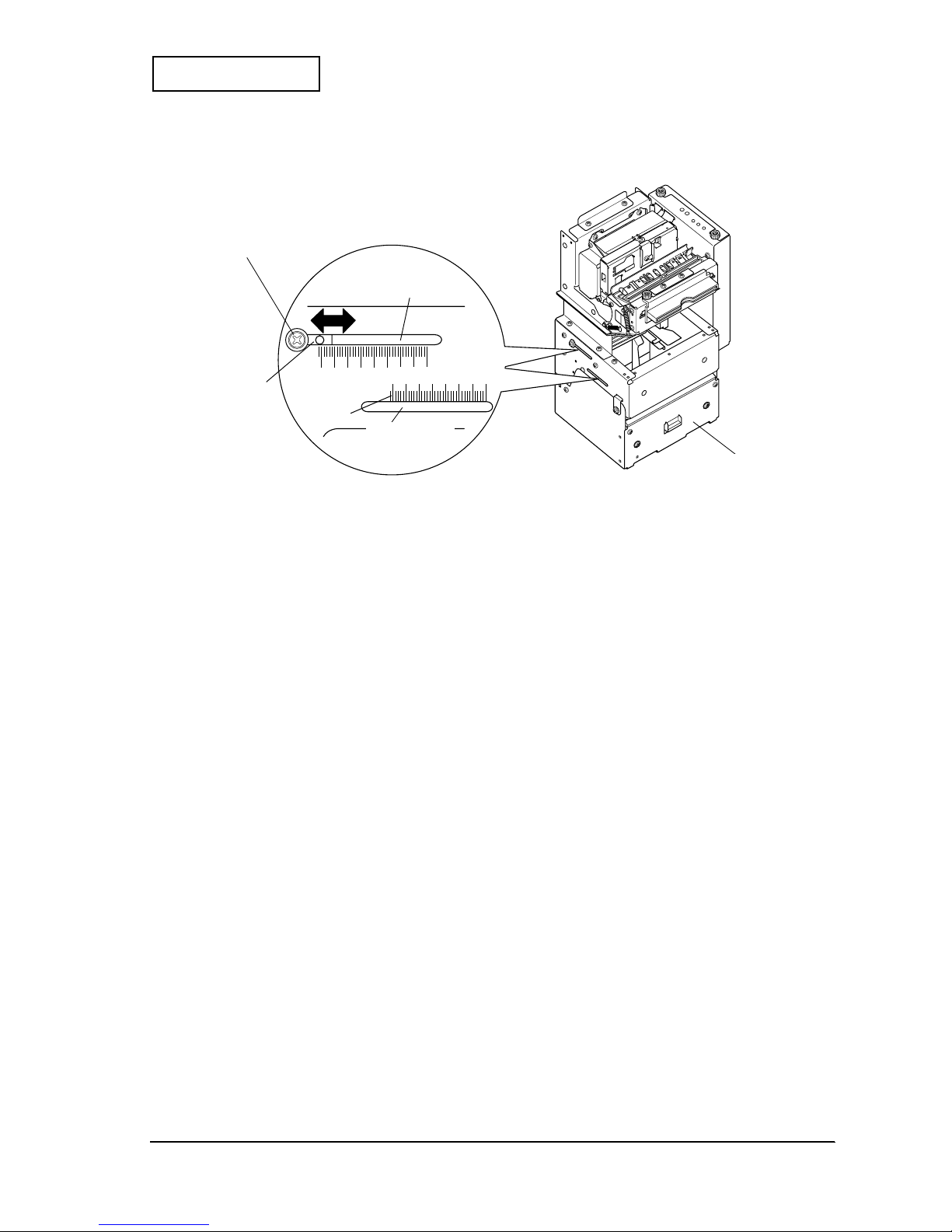
Rev. A Handling 3-11
EU-T432 Technical Manual
Confidential
Figure 3-5 Setting of the paper NE detector
paper NE detector
(back side)
screw, paper NE detector
1 2 3 4 5 6 7 8 9 (hol e No,)
paper roll supply modu le
for 6 inch type
for 8 inch type
1 to 8
Page 46

3-12 Handling Rev. A
Confidential
Self Test
The EU-T432 has self test functions. Follow the steps below to perform the self tests.
Performing the Self Test
1. With the paper loaded, turn on t he power wh ile hol ding down t he FEED button on the panel
switch. (If the power is already on, turn it off first before performing the self test with the
paper loaded.)
Figure 3-6 Performing the self test
2. The current printer status is printed.
3. When the printing is complete, the message, “If you want to continue SELF-TEST
printing, please press FEED button,” is printed; then the PAPER OUT LED starts to
flash.
4. Press the paper feed button again while the PAPER OUT LED is flashing; then the printing
(for the test pattern printing) is resumed .
Self Test End
After a number of lines are printed, the message ***completed*** is sprinted at the end of
the self test; then the unit enters the normal operational mode, with all settings initialized.
Note:
During the self test, check each LED on the circuit board. If an error occurs during the self test, see the
following section and “Troubleshooting” in Chapter 5 for details.
POWER LED
PAPER LED
FEED button
BACK button
ERROR LED
Page 47

Rev. A Handling 3-13
EU-T432 Technical Manual
Confidential
Errors
LED Display
The LED indications indicat e t he fol lowin g : the POWER LED for power supply error, the PAPER
LED for paper-out error and the ERROR LED for various kind of errors. For the LED position, see
Figure 3-6 “Performing the self test,” and for recovery from errors, see “Troubleshooting” in
Chapter 5.
POWER LED (Power Supply Error): Green
When the POWER LED is lit, the power is supplied. The LED indicates the following:.
PAPER LED (Paper-End Error): Red
When the PAPER LED is not lit, the paper roll has enough paper on it. The LED indicates the
following:
ERROR LED (Error): Red
ERROR LED has three error types: the automatic recovery error, the possible recovery error, and
the recovery impossible error. The LED indicates the following:
Automatic recovery error
Note:
The high temperature error of the print head is not an abnormality. When the head cools down to 70
°
C or
less, the unit recovers automatically.
Table 4-4 POWER LED Error
Error type LED flashing pattern Cause
Power supply error Not lit
The power supply connector is unplu gg ed .
The fuse (F1) is blown out.
Table 4-5 PAPER LED Error
Error type LED flashing pattern Cause
Paper-end error Lit
•
The paper roll is near its end or no paper is loaded.
• Α
paper jam has occurred around the detector.
•
Detector failure has occurred.
•
The connector of the detector is unplugg e d.
Waiting for self test
printing to be continued
or macro execution
ready state
Flashing
Self test printing is in th e rea dy st at e du rin g sel f test .
Table 4-6 Automatic recovery error
Error type LED flashing pattern Cause
Print head high
temperature error
The head temperature has reached 75°C or more.
→
Approx. 320 ms
Approx. 320 ms
Page 48

3-14 Handling Rev. A
Confidential
Possible recovery erro r
Recovery impossible error
Note:
When any error shown above occurs, turn off the power as soon as possible.
Table 4-7 Possible Recovery Error
Error type LED flashing pattern Cause
Platen open error Platen unit is open during printing.
Autocutter error Autocutter malfunction
Black mark sensor
detection error
No black mark is detected even after a certai n am o un t
of paper with black mark is fed.
Presenter error A paper jam has been detected in the cut sheet
presenter module.
Table 4-8 Recovery impossible error
Error type LED flashing pattern Cause
CPU execution error The CPU has executed an incorrect address.
R/W error in
memory or G/A
After R/W checking, the printer does not work correctly.
High voltage error The power supply voltage is extremely high .
Low voltage error The power supply voltage is extremely low.
PCB connection
error
The printer is not connected or the head wiring is
disconnected.
Approx. 5.12 s
Approx. 320 ms
Approx. 320 ms
Approx. 5.12 s
Approx. 5.12 s
Approx. 5.12 s
Approx. 320 ms
Approx. 5.12 s
Page 49

Rev. A Maintenance 4-1
EU-T432 Technical Manual
Confidential
Chapter 4
Maintenance
To keep the printer in peak working condition, extend its life for a long term, and prevent
operational failures, follow the maintenance procedures below.
Cleaning
CAUTION:
• Never clean the thermal head with solvents other than the specified ones, since
other solvents could damage the thermal head or cause the malfunction of
parts.
• Since the head area and each motor surface can become hot right after
printing, allow about 15 minutes for them to cool.
Thermal Head Cleaning
The head heating elements of the printer modul e will collect dust aft er printing for a lon g period
of time because of heat sensitive materials contained in the paper, that could affect printing
quality. Therefore, cleaning the thermal head using the steps below is rocommended. (See
“Opening and Closing Modules and Other Parts” on page 3-4 for opening the module and the
platen unit if necessary.)
1. Turn off the power.
2. Open the cut sheet presenter module.
3. Open the
platen unit
using the
lever, platen
, and remove the paper.
4. Wipe off the dust on the head heating elements usi ng a cotton swab dampened with alcohol
solvent, such as ethanol, or IPA.
Figure 4-1 Thermal head cleaning
5. After the alcohol evaporates completely, turn the
lever, platen
or push the
push plate,
platen B
to close the
platen unit
.
head heating elemen ts
cotton swab
lever, platen
push plate, platen, B
Page 50

4-2 Maintenance Rev. A
Confidential
Removing Stains (Except for the Thermal Head)
The areas where the paper is fed will be stained or collect dust after printing for a long time
because of paper dust and heat sensitive materials contained in the paper. Especially, if paper
feed rollers, the platen, or the paper detectors are not clean, a malfunction in paper feeding or
paper detection may occur. In this case, wipe off the stains with alcohol.
CAUTION:
Never use thinner, benzine, t richl oroethylene, or ketone group solv ents, si nce they could
damage rubber and plastic parts or cause them to deteriorate.
Removing Dirt and Dust
Use an electronic vacuum cleaner to remove dirt and dust. After cleaning, check the lubrication
point and lubricate when necessary.
Note:
When opening the units and cleaning them, be sure not to damage parts and paper detectors, disconnect
wires, or unplug connectors.
Removing Foreign Matter When the Cutter Locks
Follow the procedures below to remove foreign matter when the cutter of the printer module
locks.
After rotating the
motor
in reverse so that the
movable cutter blade, full
returns to the home
position, shut off the current to the
motor
; then remove any foreign matter. (See Figure 2-20 on
page 14 in Chapter 2 for checking the home position.)
If the
movable cutter blade, full
fails to return to the home position even after executing the
above procedure, follow the steps below.
1. Shut off the current to the
motor
.
2. Rotate the knob on the
gear, cutter w o rm
with a tool, such as tweezers, so that the
movable cutter blade, full
returns to the home position; then remove the foreign
matter.
Page 51

Rev. A Maintenance 4-3
EU-T432 Technical Manual
Confidential
Inspection
The maintenance and inspection procedures for the printer fall into two categories. One is
“Daily checks” for the printer user, and the other is “Periodic checks” for someone with more
technical knowledge. Maintenance and inspect ion procedures should be carri ed out by properly
qualified personnel.
Daily Checks
Make sure the printer is used properly and kept in good repair. If there are any problems,
correct them using procedures in the table below. The items to be checked are as follows:
Periodic Checks
Every six months, check the items listed in the table below. If there are any problems, correct
them using procedures in the table below.
Table 4-1 Daily Checks
Check item Standard Procedure
Setup status No cables or connectors are
disconnected.
Connect the cables or connectors
properly.
Paper roll is loaded properly. Load the paper properly.
No units or modules such as the paper roll
supply module, the platen unit, the cut
sheet presenter module, the cover, circuit
board are open.
Close the units or the modules.
Paper chips or foreign
matter inside the
product
No paper chips or for eign matter is in side
the product
Remove paper ch ips or foreign matter.
Paper state Specified paper is used. Replace with the specified paper
No discolored or torn paper is used. Replace with a new paper roll.
Table 4-2 Periodic Checks
Check item Standard Procedure
Dust, fuzz, o r di r t st i ck ing
to various parts
No dirt or dus t is on any par t s or collect ed
in the paper path.
Remove dust, fuzz, or dirt with a vacuum
cleaner.
No paper chips or foreign matter is in the
areas such as around the thermal head
heating elements, the cutter, gears,
detectors, and inside the paper path.
• Wipe off dirt an d dust with alcohol.
• Remove foreign matter or paper chips.
• Wipe the platen surface with alcohol
when paper chips have accumulated.
Lubrication stat u s Lubri c at io n is sa ti s fac t ory . Lubricate the lubric at io n points if
required.
Operating status
• Printing, paper feeding and issuing
operation s perform properly.
• No abnormal sound
• All other functions perform properly and
parts are not deformed or worn.
See “Troubleshooting” on page 5-2.
Page 52

4-4 Maintenance Rev. A
Confidential
Lubrication
Lubrication is particularly important in keeping the printer operating properly as long as
possible. Therefore, lubricate at prescribed intervals, using the correct lubricants.
Lubricant
The performance and durability of the printer are greatly affected by the lubricant applied.
Therefore, pay careful attention to lubricant specifications, especially for the low temperature
characteristics. The lubricants for t he printer are chosen based on tec hnica l in fo rmat ion ana lysis
and tests on various lubricants by EPSON. The lubricants are available in 40 cc (gr.) plastic
containers (the minimum supply unit). Both G-36 and G-15 are used on this printer.
Lubrication Standards
Lubricate the printer in the following situations:
❏ Lubricant is wiped off during cleaning.
❏ Lubricant is wiped off when disassembly or assembly is performed.
When lubricating parts during assembly of the printer, clean parts before lubricating them.
Refer to the next section and “Lubrication Diagram” at the end of this manual for the lubricants
and the lubrication points .
Lubrication Point
The lubrication points are as follows:
Note: The lubrication point numbers in the table are the same as those in the lubrication diagrams at the end of this manual.
Table 4-2 Lubrication Point
Module Number Lubrication point
Lubrication
type Amount of lubricant
Printer
module
1 Two points where the screw on the
lock lever
is
secured
G-15 1 mm-diameter
lubricant
2 to 7 The seven points where the gears on the
autocutter
are engaged with other parts.
G-36 Appropriate quantity
8 The oval hole on the
movable cutter blade
(Two points)
G-15 1 mm-diameter
lubricant
9 The two points where the
cutter frame
contact the
fixed blade
.
G-15 1 mm-diameter
lubricant
10 The two points where the shaft of the
movable
cutter blade
rotates.
G-15 Appropriate quantity
11 The dowels where the platen unit rotates. G-36 Until the dowels are
covered.
12 The points where the
frame assembly
contacts the
lock lever assembly
.
G-15 1 mm-diameter
lubricant
fixing plate,
printer
13 Two points where the cut sheet presenter module
turns
G-36 Appropriate quantity
Cut sheet
presenter
module
14 The gear on the paper feed motor G-36 Appropriate quantity
Page 53

Rev. A Maintenance 4-5
EU-T432 Technical Manual
Confidential
Lubricant List
Tools
Table 4-3 Lubricant List
Type Name Quantity Commercial availability
Grease
G-15 40 gr
Epson exclusive product
Grease G-36 40 gr
Table 4-4 Tool List
Tool name Commercial availability
Brush #1 Yes
Cleaning brush Yes
Crosshead screwdriver #0, 1 and 2 Yes
ET holder No. 1.5, 2, 2.5, 3, 3.5 and 4
Yes
Tweezers Yes
Diagonal cutting nippers
Yes
Pliers
Yes
Electric solder iron
Yes
Wrist band
Yes
Table 4-5 Measuring Equipment List
Name Standard
Multimeter DC vol ta ge: 400 V max.
Resistanc e: measurable
Oscilloscope 500 MHz with storage
Page 54

Rev. A Repair 5-1
EU-T432 Technical Manual
Confidential
Chapter 5
Repair
Repairs are divided into two levels (A and B) in consideration of the degree of difficulty of
repair. The person who repairs the printer should perform the proper repair procedures,
depending on the individual technical knowledge and skills.
Repair Levels
Repair Procedure
When problems occur, check the condition of the printer and locate the cause of the problem as
outlined in “Troubleshooting Table.” Then repair the unit properly. The table consists of the
following five sections.
Level A: Requires general knowledge of the printer’s operation
principles and structure but does not require specialized
experience.
Level B: Requires a certain degree of knowledge of the printer’s
operating principles and structure as well as skills and
experience using special tools for disassembly and assembly
of the printe r.
Phenomenon Find the type of problem in this column.
Condition Check the condition of malfunction by referring to this
column.
Cause Locate the cause of the problem by referring to this column.
Also, the repair level is indicated for each cause; use this
indicatio n to determine the method of repair.
Where/ how to check The mechanisms that may cause problems as well as
checkpoints are listed in this column. Check the unit as
outlined in this column to locate the malfunctioning section.
Procedure Repair malfunctioning sections as indicated in this column. If
the same problem or phenomenon reoccurs af ter the specified
repair is performed, check other items in t he “Cause” col umn
and repair the unit again.
Page 55

5-2 Repair Rev. A
Confidential
Troubleshooting
Use troubleshooting procedures in the table below when problems occur.
Table 5-1 Troubleshooting
Phenomenon Condition Cause Level Where/how to check Procedure
No
performance
Power (24 V) is
not supplied
Power connector is
disconnected.
A See if the power
connector is
connected properly.
Connect the power
connector again.
POWER LED is not
lit.
Fuse (F1) is blown.
B Check with a tester if
the fuse (F1) on the
control circuit board is
conductive.
•Replace the blow n
fuse.
•Replace the
control circuit
board if there is no
recovery after the
fuse replacement.
PAPER LED is lit. Paper out error (1) Paper is not
loaded in the
printer.
A Check if the paper is
loaded.
Load the paper in
the printer.
(2)Only a small
amount
remaining on
the paper roll
(paper NE
detected)
A Check the amount of
the paper remaining in
the paper supply
module.
Replace the paper
roll if only a small
amount of the
paper remaining is
left.
PAPER LED is
not lit even
when the
paper is out.
Paper detector
failure
(1)Paper chips or
foreign matter is
jammed around
the paper
detector.
A
Check whether paper
chips or foreign matter
is jammed around the
paper detector.
Remove the paper
chips or foreign
matter if there is
any.
(2)Paper chips or
foreign matter is
jammed around
the paper NE
detector.
A
Check whether paper
chips or foreign matter
is jammed around the
paper NE detector.
Remove the paper
chips or foreign
matter if there is
any.
PAPER LED is lit
even when the
paper is not
out.
Paper detector
failure
(1) Paper NE
connector is
disconnected.
A
Check if the paper NE
detector is connected
properly.
Connect the
connector properly
if it is disconne cted.
(2)Paper NE
detector is
damaged.
B Chec k t he paper NE
detector function with
an oscilloscope.
Replace the paper
NE detector if it is
damaged.
(3)Paper detector is
disconnected .
A Check if the paper
detector is connected
properly.
Connect the
connector properly
if it is disconne cted.
(4)Printer detector
is damaged.
B Check t he paper
detector function with
an oscilloscope.
Replace the paper
detector if it is
damaged.
(5)Printer FFC is
disconnected.
A Check if the printer FFC
is connected properly.
Connect the FFC if it
is disconnected.
Page 56

Rev. A Repair 5-3
EU-T432 Technical Manual
Confidential
PAPER LED is
flashing.
Self test standby
state
Self test is in the
standby state
A Check if the self test
printing is completed.
Press paper feeding
SW on the control
circuit board to
complete the self
test when not
completed.
ERROR LED is
flashing.
(For the LED
flashing
patterns , see
“Error LED” on
page 3-12.)
Print head high
temperature
error
The head
temperature has
reached at 75°C or
more.
A −
−
(When the head is
cooled down to
70°C or less, the unit
will recover
automatica lly .)
ERROR LED is
flashing
(For the LED
flashing
patterns , see
“Error LED” on
page 3-12.)
Platen open error The platen is open. A
Check if the platen is
not open.
Close the platen
when it is open.
Platen open is
not detected.
The platen open
detector is
damaged.
B Check the platen open
detector function with
an oscilloscope.
Replace the
detector if it is
damaged.
Autocutter error (1)Paper chips or
foreign matter is
inside the
autocutter and
has locked it.
B Check whether paper
chips or foreign matter
is jammed inside th e
autocutter.
After turning off the
power, remove
paper chips or
foreign matter; then
turn on the power.
(2)The internal
function of the
autocutter is
damaged.
B Che ck the power
supply voltage.
Replace the
autocutter if the
power supply
voltage is normal.
Black mark
detection error
(1)No black mark is
printed.
A Check if the paper is
printed with a black
mark.
Replace with the
black mark printed
paper.
(2)The wrong side
of the paper is
used.
A Check if the correct
side of the paper is
used.
Replace with the
paper with the
black mark on the
correct side.
(3)The black mark
detector is
damaged.
B Che ck the black mark
detector function with
an oscilloscope.
Replace the
detector if it is
damaged.
(4)Paper chips or
foreign matter is
jammed around
the black mark
detector.
A
Check whether paper
chips or foreign matter
is jammed around the
black mark detec t or.
Remove the paper
chips or foreign
matter if there is
any.
Table 5-1 Troubleshooting
Phenomenon Condition Cause Level Where/how to check Procedure
Page 57

5-4 Repair Rev. A
Confidential
Printing
operation does
not work.
Nothing is
printed.
(1) The head FFC
connection
failure
A Check whether the
head FFC is connected
properly.
Connect the head
FFC properly.
(2)The head FFC
signal line is
broken.
A See or check with an
oscilloscope whether
there is damage or
break of the head FFC.
Replace the head
FFC if it is broken.
(3)Head input pulse
failure
B
Check with an
oscilloscope whether
the input pulse is within
the specified range.
If the input pulse is
abnormal , re pla c e
the control circuit
module.
(4)Head failure
(Dr.IC, etc.)
B
If the input pulse is
normal, replace the
thermal head.
Dots are missing
continuously.
(1)Foreign matter is
attached to the
head heating
elements
A
See if anything is wrong
with the head heating
elements
Clean the head
heating elements if
foreign matter
attached.
(2)The head
heating
elements are
damaged.
A Replace the thermal
(3)Head failure
(Dr.IC, etc.)
B
Check with an oscilloscope if the inpu t pulse
is within the specified
range.
If the input pulse is
normal, replace the
thermal head.
Dots are missing
occasionally.
(1)Foreign matter
is on the surface
of the platen.
A Check the surface of
the plate n with an
oscilloscope or a
magnifier.
Clean the surface of
the platen if foreign
matter is attached
to it.
(2)The platen
surface is
deformed.
A
Replace the platen
if there is any
damage on the
platen surface.
Table 5-1 Troubleshooting
Phenomenon Condition Cause Level Where/how to check Procedure
Page 58

Rev. A Repair 5-5
EU-T432 Technical Manual
Confidential
Printing is faint. All printing color is
faint.
Printing dens ity
setting is set to light.
(The color sensitiv ity
difference
depending on the
paper)
B •Check the printing
density setting of the
control circuit module.
•Check if the specifie d
paper is used.
Change the setting
of the printing
density to darken.
All or some part
of printing is faint.
(1)Dirt or foreign
matter attaches
to the head
heating
elements.
A See or check the head
heating elements with
a magnifier.
Clean the head
heating elements if
foreign matter is
attached to the
elements.
(2)Thermal
sensitivity has
deteriorated
due to paper
deterioration
A Check whether the
paper has
deteriorated.
Replace the
deteriorated paper.
(3)Therma l head
heating
elements are
defective.
B Check the surface of
the thermal head with
a magnifier.
Replace the thermal
head.
Printing is partly
faint.
Damage or
deformation of th e
platen surface
A See or check with a
magnifier the platen
surface.
Replace the platen
if the platen surface
is damaged or
deformed.
Abnormal or
incorrect
printing
Abnormal or
incorrect printing
(1)Thermal head
input pulse
failure
B
Check with an oscilloscope if t h e input pul se
is within the specified
range.
If the input pulse is
abnormal, replace
the control circuit
board.
(2)Therma l head
failure
(Dr.IC, etc.)
B
If input pulse is
normal, replace the
thermal head.
Paper cannot
be inserted.
Paper cannot be
inserted into the
printer module.
(1)Paper chips or
foreign matter is
in the paper
guide of the
printer module.
A Check whether pa per
chips or foreign matter
is inside the paper
guide.
Remove paper
chips or foreign
matter if th ere is
any.
(2)Paper detector
on the paper
guide of the
printer module i s
defective.
B Check if the detector
operates properly.
•Remove paper
chip or foreign
matter if the re is
any.
•Replace the
detector if it is
damaged.
(3)The shape of the
paper edge is
not like the
specified one.
A Check if the paper
edge is cut properly.
Cut the paper edge
properly.
Table 5-1 Troubleshooting
Phenomenon Condition Cause Level Where/how to check Procedure
Page 59

5-6 Repair Rev. A
Confidential
Paper is not
fed.
Paper is not fed
smoothly.
(1)The paper roll
supply module
does not
oscillate
properly.
B Check if the paper is
pulled out smoothly.
(The paper tension
loading should be les s
than the rating value.)
•Load the paper
properly.
•Replace the paper
roll supply module if
the oscillation
loading of the
paper supply
module is
excessive.
(2) The paper size is
not correct.
A Check the paper
diameter, width, and
thickness.
Use the specified
paper.
Paper is not fed.
(1)Abnormal input
signal or paper
feed motor
failure
B Che ck the power
supply voltage, input
signal, and operation
of each paper feed
motor.
•Replace the
control circuit
board module if
there is any
problem with the
power supply
voltage, input
signal.
•Replace the motor
if there is any
problem with the
motor operation.
(2)The paper feed
connector is
disconnected.
A
Check if each paper
feed motor is
connected properly.
Connect the
connector properly.
(3)Power
transmission parts
(gears) are
damaged, or
foreign matter is
caught between
gears.
B
•Check the power
transmission state of
each gears.
•Check if no foreign
matter is caught
between geas.
•Replace damaged
gears.
•Remove foreign
matter if there is
any.
Paper feeding
pitch is
defective.
The character
spacing is not
uniform.
(1)The paper roll
supply module
does not
oscillate
properly.
B Check if the paper is
pulled out smoothly.
(The paper tension
loading should be les s
than the rating value.)
•Load the paper
properly.
•Replace the paper
roll supply module if
the oscillation
load of the paper
supply module is
excessive.
(2)Power
transmission parts
(gears) are
damaged, or
foreign matter is
caught between
gears.
B
•Check the power
transmission state of
each gear.
•Check if no foreign
matter is caught
between gears.
•Remove foreign
matter if th ere is
any.
•Replace damaged
gears .
Table 5-1 Troubleshooting
Phenomenon Condition Cause Level Where/how to check Procedure
Page 60

Rev. A Repair 5-7
EU-T432 Technical Manual
Confidential
Paper feeding
pitch is
defective.
The character
spacing is not
uniform.
(3)Abnormal input
signal or paper
feed motor
failure
B Che ck the power
supply voltage, input
signal, and operation
of each paper feed
motor.
•Replace the
control circuit
board module if
there is any
problem with the
power supply
voltage, input
signal.
•Replace the motor
if there is any
problem with the
motor operation.
(4)Paper feed slip
due to the
platen wear and
paper powder
B Check the friction f orce
of the platen surface.
•Clean the platen if
paper powder
accumulates o n it .
•Replace the platen
if it is worn out.
Paper cannot
be cut.
Paper is not cut
automatically.
(1)Foreign matter
inside the
autocutter
A Check whether foreign
matter is inside the
autocutter.
Remove foreign
matter if there is
any.
(2)Abnormal input
signal or inner
mechanism
damage of the
autocutter
B Che ck the power
supply voltage, input
signal, and operation
of the cutter motor.
•Replace the
control circuit
board module if
there is any
problem with the
power supply
voltage, input
signal.
•Replace the motor
if there is any
problem with the
autocutting
operation.
Platen unit can
not open/
close.
Platen unit do es
not open.
The cutter blade is
not in the home
position.
B Check if the cutter
blade is in the home
position.
Turn the knob to
return the cutter
blade to the home
position.
Platen unit do es
not close.
Foreign matter
inside the printer.
A Check whether foreign
matter is inside the
printer.
Remove foreign
matter if there is
any.
Table 5-1 Troubleshooting
Phenomenon Condition Cause Level Where/how to check Procedure
Page 61

Rev. A Assembly and Disassembly 6-1
EU-T432 Technical Manual
Confidential
Chapter 6
Assembly and Disassembly
Small Parts Abbreviation
All small parts are represented by the abbreviations listed below
Table 6-1 Small Parts Abbreviations
記号
記号記号
記号 部品名称
部品名称部品名称
部品名称
R.E Retaining ring E-type
C-ring Crescent ring
C.B. (M2 × 2.5) Cross-recessed binding head machine screw, 2 × 2.5, F/Zn
C.B. (M2 × 3) Cross-recessed bin d in g head mac hi ne screw, 2 × 3, F/Zn
C.B. (M2.3 × 3) Cross-recessed bin d ing head mac hine screw, 2.3 × 3, F/Zn
C.B. (M2.5 × 4) Cross-recessed bin d ing head mac hine screw, 2.5 × 4, F/Zn
C.B. (M3 × 4) Cross-recessed bin d in g head mac hi ne screw, 3 × 4, F/Zn
C.B.(M3 × 6) Cross-recessed binding head machine screw, 3 × 6, F/Zn
C.B.(M3 × 8) Cross-recessed binding head machine screw, 3 × 8, F/Zn
C.B.(M4 × 16) Cross-recessed binding head machine screw, 4 × 16, F/Zn
C.B.B-tite (M2 × 6) Cross-resessed binding he ad B-tite self tapp in g screw, 2 × 6, F/Zn
C.B.P-tite (M3 × 8) Cross-resessed binding hea d P-tite self tapping s crew, 3 × 8, F/Zn
C.B.S-tite (M2.5 × 4) Cross-recessed binding head S-tite se lf tapping screw, 2 .5 × 4, F/Zn
C.B.S-tite (M3 × 5) Cross-rec e s s ed binding head S-tite self ta pping screw, 3 × 5, F/Zn
C.B.S-tite (M3 × 12) Cross-recessed bi n ding head S-ti te self tapping scr e w, 3 × 12, F/Zn
C.C.P-tite (M2.5 × 6) Cross-resessed cup head P-tite self tapping screw, 2.5 × 6, F/Zn
C.F. (M3 × 8) Cross-resessed flat head screw, 3 × 8, F/Zn
C.P-tite F screw (M2 × 3) Cross-resessed 3P-tite self tapping sc rew F, 2 × 3, F/Ni
C.P (P2) Cross-recessed pan head screw, 3 × 6, F/Zn
C.P (S-P1) (M1.6 × 5) Cross-recessed pan head screw with S.W.+P.W.1, 1.6 × 5, F/Zn
C.P. (M2 × 2) Cross-recessed pan head screw-3, 2 × 2, F/Ni
C.P. (M2 × 6) Cross-recessed pan head machin e screw, 2 × 6, F/Zn
H. nut (3) Hexagonal nut double chamfered, 3, F/Zn
H. nut (4) Hexagonal nut double chamfered, 4, F/Zn
P. washer (4.3 ×0.8 × 8) Plain washer (4.3 ×0.8 × 8)
P. washer (3 ×0.5 × 7) Plain washer (3 ×0.5 × 7)
P. washer (3.7 ×0.5 × 8) Plain washer (3.7 ×0.5 × 8)
Conical S. washer-1L, 4 Conical spring washer, Class 1, light load, 4, S/Na
S. washer-2, 4 Spring washer No.2, 4, F/Zn
Page 62

6-2 Assembly and Disassembly Rev. A
Confidential
Disassembly
❏ For disassembly, follow the assembly procedures described in “Assembly” in r everse
sequence.
❏ Disassembly of the modules beyond the level show in the exploded diagrams at the end of
this manual may result in dama ge to the module s and their function s.
Assembly
❏ The assembly process is divided into pre-assembly and main assembly. First perform the
pre-assembly; then proceed to the main assembly after the components have been
assembled into units.
❏ Perform assembly while referring to the component shapes and mounting positions shown
in the exploded diagrams at the end of this manual.
❏ The ★ symbols in the “Reassembly step” indicate places where checks are required. Make
sure to follow the instructions given in these places.
❏ Circled numbers in the “Reassembly step” indicate that lubrication is required during the
reassembly of that component and that such lubrication will be difficult unless performed
during reassembly.
❏ Refer to “Lubric ation” in Chapt er 4 for lubrication details on th e printer module and other
modules. Also, see the lubrication diagrams at the end of this manual for the places to
lubricate.
In this assembly section, assembly steps are described as the following sequence:
❏ Installation of the printer module (Pre-assembly A to F and Main Assembly A to L {page 3 to
29})
❏ Installation of th e other modules (Pre-assembly A to H and Main Assembly A t o E {page 30
to 57})
The Main assembly A to E in the other modules’ assembly is the assembly for the all preassembled modules including the printer module.
Page 63

Rev. A Assembly and Disassembly 6-3
EU-T432 Technical Manual
Confidential
Installation of the Printer Module
Pre-assembly A: Paper guide,straight, back unit
Reassembly
step
Part name Assembly procedure
1
Paper detector assembly
2
Paper guide, straight, back
❏ Slide the
paper detector assembly
onto the
paper guide, straight, back
.
★
<Check>
❏
Make sure that the
paper detector asse mbly
is installed securely, as shown
below.
paper detector
assembly
paper guide, straight, back
Install securely.
Page 64

6-4 Assembly and Disassembly Rev. A
Confidential
Pre-assembly B: Frame, platen, straight unit, B
Reassembly
step
Part name Assembly procedure
1
Frame, platen
2
Lock lever assembly
C.B.B-tite (M2
×
× ×
×
6)
× 1
❏
Install the
lock lever assembly
on the
frame, platen
, and secure it with a
screw.
★
<Check>
❏
Tightening torque: 294 to 343 mN•m {3.0 to 3.5 kg•cm}
❏
Make sure that the screw does not skew during tightening.
3
Cover, fixed blade
4
Fixed blade
❏
Install the
cover, fixed blade
and the
fixed blade
on the
frame, platen
;
then secure them with
shouldec
s.
5
Spring, fixed blade
Shouldec (2
×
× ×
× 6 ×
× ×
× 2) × 2
At this time, inst al l the
spring, fixed blade
on one of the
shouldec
s, as
shown below.
★
<Check>
❏
Tightening torque: 177 to 226 mN•m {1.8 to 2.3 kg•cm}
❏
Make sure to install the
fixed blade
right-side-up.
❏
Make sure that the dowels on the
frame, platen
fit securely into the holes
on the
cover, fixed blade
.
❏
Make sure to install the
spring, fixed blade
in the correct position.
C.B.B-tite (M2 × 6)
lock lever assembly
frame, platen
shouldecs
spring, fix e d blade
fixed blade
mounting dowels
cover, fixed blade
frame, platen
Page 65

Rev. A Assembly and Disassembly 6-5
EU-T432 Technical Manual
Confidential
Pre-assembly B
Reassembly
step
Part name Assembly pr oc edure
6
Push plate, platen, B
C.C.P-tite (M2.5
×
× ×
×
6)
× 1
❏
Install the
push plate, platen, B
to the
frame, platen
and secure it with a
screw.
★
<Check>
❏
Tightening torque: 490 to 539 mN•m {5.0 to 5.5 kg•cm}
7
Spring, lock lever
❏
Hook the ends of the
spring, lock lever
onto the
lock lever assembly
and
C.B.B-tite (M2
×
× ×
×
6)
from the inside of the
frame, platen
.
★
<Check>
❏
Make sure that the
spring, lock lever
is hooked securely.
push plate, platen, B
frame, platen
C.C.P-tite (M2.5 × 6)
C.B.B-tite (M2 × 6)
spring, lock leve r
lock lever assembly
frame, platen
Page 66

6-6 Assembly and Disassembly Rev. A
Confidential
Pre-assembly B
Reassembly
step
Part name Assembly pr oc edure
8
Platen, straight assembly
9
⑩
Bearing, platen
R.E. (2.5)
× 1
❏
After Installing the
platen, straight assembly
to the
frame, platen
, install the
bearing, platen
from the outside of th e
frame, platen
; then secure it with
an
R.E.
❏
Lubricate with G-15 two points where the screw on the
lock lever
assembly
is secured.
platen, straight
assembly
bearing, platen
R.E.(2.5)
bearing,
platen
frame, platen
G-15
Page 67

Rev. A Assembly and Disassembly 6-7
EU-T432 Technical Manual
Confidential
Pre-assembly C: Cutter motor assembly
Reassembly
step
Part name Assembly procedure
1
Microswitch
2
Lead wire, paper cutter
❏
Solder the white lead wire of the
lead wire, paper cutter
to the
microswitch
.
3
Cutter motor sub-assembly
❏
Solder the red wire of the
lead wire, paper cutter
to the red marked
terminal side of the
cutter motor sub-assembly
, and solder the black lead
wire to the other terminal.
★
<Check>
❏
Make sure to arrange the lead wires properly .
microswitch
white
lead wire, paper cutter
black
red
*No polarity
red mark
red
black
lead wire,
paper cutter
cutter motor
sub-assembly
Page 68

6-8 Assembly and Disassembly Rev. A
Confidential
Pre-assembly D: Cutter, cover sub-unit
Reassembly
step
Part name Assembly procedure
1
Cutter, cover sub-assembly
②
Gear, cutter worm
❏
Lubricate with G-36 the bore of the
gear, cutter worm
and the point
where the
gear, cutter worm
comes in contact the
cutter, cover sub-
assembly
; then install it on th e
cutter, cover sub-assembly.
③
Gear, reduction A/C
4
Washer, clutch
5
Spring, cutter clutch
❏
After lubricating the bore of the
gear, reduction A/C
with G-36, attach the
washer, clutch
and the
spring, cutter clutch
to the
gear, reduction
A/C
; then, install it to the
cutter cover sub-assemb ly
.
★
<Check>
❏
Make sure not to damage the clutch teeth when installing the
gear,
reduction A/C
.
gear, cutter worm
G-36
cutter, cover sub-assembly
G-36
G-36
clutch teeth
G-36
G-36
washer, clutch
spring, cutter clutch
gear, reduction A/C
cutter, cover sub-assembly
Page 69

Rev. A Assembly and Disassembly 6-9
EU-T432 Technical Manual
Confidential
Pre-assembly D
Reassembly
step
Part name Assembly procedure
6
Shaft, reduction A/C
❏
Insert the
shaft, red uct i on A/ C
to the bores of the
gear, reduction A/C
and
the
gear, cutter worm
.
★
<Check>
❏
Make sure that the
shaft, reduction A/C
is oriented properly before
insertion.
7
Cutter, motor assembly
C.B.(M2
×
× ×
×
2.5)
× 1
Screw, switch
❏
Install the
cutter, motor
to the
cutter cover sub-ass em b ly
, and secure it
with the
C.B.(M2
×
× ×
×
2.5).
❏
Install the
microswitch
to the
cutter cover sub-assembly
, and secure it with
the
screw, switch.
★
<Check>
❏
Tightening torque: 245 to 294 mN•m {2.5 to 3.0 kg•cm} (
C.B.(M2
×
× ×
×
2.5)
)
❏
Tightening torque: 108 to 147 mN•m {1.1 to 1.5 kg•cm} (
screw, switch
)
❏
Make sure to install the
cutter, motor
with the labeled side down.
❏
Make sure that the
cutter, motor
is installed sec urely.
❏
Make sure that the dowel on the
microswitch
fits securely in the mounting
hole on the
cutter cover sub-assemb ly
.
shaft, reduction A/C
spring, cutter clutch
gear, reduction A/C
gear, cutter worm
screw, switch
C.B.(M2 × 2.5)
microswitch
cutter motor
cutter cover
sub-assembly
mounting ho le
Page 70

6-10 Assembly and Disassembly Rev. A
Confidential
Pre-assembly D
Reassembly
step
Part name Assembly procedure
⑧
Cutter drive gear
sub-assembly
Plain washer (3
×
× ×
×
0.5
×
× ×
× 7) × 1
R.E. (2.5)
× 1
❏
After lubricating the shaft on the
cutter cover sub-assemb ly
with G-36,
install the
cutter drive gear sub-assembly
and the
plain washer
on the shaft; then secure them with an
R.E
.
★
<Check>
❏
Make sure not to apply excessive pressure to the
microswitch
actuator
when installing the
cutter drive gear sub-assembly
.
❏
Make sure not to damage the
cutter drive gear sub-assembly
when
securing it with the
R.E.
⑨
❏
Lubricate the specified areas with G-36.
R.E.(2.5)
plain washer
cutter drive gear
sub-assembly
cutter motor
microswitch actuator
G-36
G-36
G-36
G-36
G-36
Page 71

Rev. A Assembly and Disassembly 6-11
EU-T432 Technical Manual
Confidential
Pre-assembly E: Cutter unit, B
Reassembly
step
Part name Assembly p ro ce d u re
1
Cutter cover sub-uni t
2
Cutter frame assembly
C.B.S-tite (M3
×
× ×
×
5)
× 1
❏
Pass the
lead wire, paper cutter
through the hole on the
cutter frame
assembly
and secure the
cutter cover sub-unit
and the
cutter frame
assembly
with a screw.
❏
When putting the
cutter cover sub-un it
and the
cutter frame assembly
together, insert the
shaft, movable cutter blade drive
into the oval hole
on the
movable cutter blade
.
★
<Check>
❏
Tightening torque: 834 to 932 mN•m {8.5 to 9.5 kg•cm}
❏
Make sure that the
shaft, movable cutter blade drive
fits securely into the
oval hole on the
movable cutter blade
.
❏
Make sure that the edges of the
cutter cover sub- uni t
fit into the hooks on
the
cutter frame assembly
.
C.B.S-tite (M3 × 5)
oval hole
lead wire, paper
cutter
cutter cover, sub-unit
cutter frame assembly
shaft, movable cutter
blade drive
hook
hook
cutter frame assembly
shaft, movable cutter
blade drive
oval hole
cutter cover, sub-unit
cutter cover, sub-unit
Page 72

6-12 Assembly and Disassembly Rev. A
Confidential
Pre-assembly E
Reassembly
step
Part name Assembly p ro ce d u re
3
Emergency cutter, full, B
C.B.(M2
×
× ×
×
2.5)
× 2
❏
Install the
emergency cutter, full, B
to the
cutter cover sub-unit
with
screws.
★
<Check>
❏
Tightening torque: 98 to 147 mN•m {1.0 to 1.5 kg•cm}
❏
Make sure that the dowels on the
cutter cover sub-unit
is fitted in the holes
on the
emergency cutter, full, B
.
4
Plate, A/C assembly
❏
Peel the backing off of a couple-face tape .
❏
Hook the bent part of the
plate, A/C
to the edge of the
cover, cutter
.
❏
Align parts A and B with the holes on the
plate, A/C
as shown below, and
stick the plate to the cutter cover sub-unit.
C.B.(M2 × 2.5)
mounting
position
emergency cutter, full, B
plate, A/C
cutter cover sub unit
A
B
Page 73

Rev. A Assembly and Disassembly 6-13
EU-T432 Technical Manual
Confidential
Pre-assembly F: Black mark detector sub-assembly (option)
Reassembly
step
Part name Assembly p ro ce d u re
1
Black mark (B.M.) sub assembly
2
Paper guide
C.P-tite F screw (M2
×
× ×
× 3)
× 1
❏
Install the
B.M. detector sub-assembly
in one of the two detector
mounting holes on the
paper guide
, and secure it with a screw. Both the
straight path and the curv ed path types can be installed this wa y.
★
<Check>
❏
Tightening torque: 167 to 186 mN•m {1.7 to 1.9 kg•cm}
❏
Make sure that the detector fits securely into the detector mounting hole
on the
paper guide
.
C.P-tite. F screw (M2 × 3)
B.M. detector sub -assembly
paper guide
mounting hole
Page 74

6-14 Assembly and Disassembly Rev. A
Confidential
Main Assembly A: Motor, paper feed, receipt, B and Platen detector
Reassembly
step
Part name Assembly procedure
1
Frame assembly
2
Motor, paper feed, receipt,
B
C.B.S-tite (3
×
× ×
×
5)
× 2
❏
Align the
motor, paper feed, receipt, B
with the mounting position on the
frame assembly
and secure it with scerws.
★
<Check>
❏
Tightening torque: 834 to 932 mN•m {8.5 to 9.5 kg•cm}
❏
Make sure that the
motor, paper feed, receipt, B
is oriented properly
.
3
Platen detector assembly
C.P. (1.6
×
× ×
×
5)
× 1
❏
Align the
platen detector assembly
to the mounting position on the
frame
assembly
, and secure it with a screw.
motor, paper feed, receipt, B
C.B.S-tite (3 × 5)
frame assembly
frame assembly
platen detector
assembly
C.P. (1.6 × 5)
Page 75

Rev. A Assembly and Disassembly 6-15
EU-T432 Technical Manual
Confidential
Main Assembly A
Reassembly
step
Part name Assembly procedure
★
<Check>
❏
Tightening torque: 147 to 196 mN•m {1.5 to 2.0 kg•cm}
❏
After installing the
platen detector assembly
, arrange the lead wires.
lead wires
Page 76
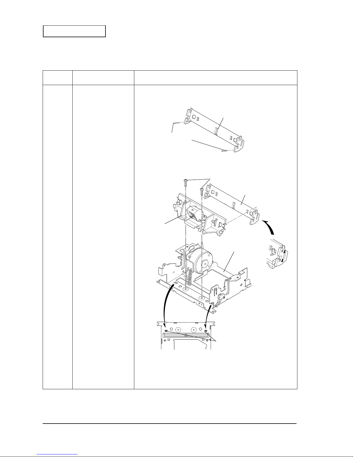
6-16 Assembly and Disassembly Rev. A
Confidential
Main Assembly B: Paper guide, straight, front and Paper guide, straight, back unit
Reassembly
step
Part name Assembly p ro ce d u re
1
Paper guide, straight, front
2
Pin, guide, straight
× 2
❏
Insert the
pin, guide, straight
into the holes on the
paper guide, straight,
front
.
3
Paper guide, straight, back
unit
C.B. (2.5
× 4
× 4 × 4
× 4
)
× 2
❏
After putting the
paper guide, straight, front
and the
paper guide, straight ,
back unit
together, install them to the mounting holes on the
frame
assembly
and secure them with screws.
paper guide, straight, front
pin, guide, straight
C.B. (M2.5 × 4)
frame, assem bly
paper guide, straight,
back unit
mounting hole s
paper guide, straight, front
Page 77

Rev. A Assembly and Disassembly 6-17
EU-T432 Technical Manual
Confidential
Main Assembly B
Reassembly
step
Part name Assembly p ro ce d u re
★
<Check>
❏
Tightening torque: 441 to 490 mN•m {4.5 to 5.0 kg•cm}
❏
The dowels on t h e
paper guide, straight, back unit
fit securely into the
holes on the
frame assembly
.
❏
Make sure that the lead wires of the
paper detector assembly
are not
caught between the
frame assembly
and the
paper guide, straight,
back unit
.
❏
Make sure that the wires of the
paper detector assembly
are passed
under the hook on the
paper guide, straight, back unit.
hook
paper guide, straight,
back unit
Page 78

6-18 Assembly and Disassembly Rev. A
Confidential
Main Assembly C: Frame, platen, straight unit
Reassembly
step
Part name Assembly p ro ce d u re
➀
❏
Lubricate the dowel on the
frame assembly
with G-36.
➁
❏
Lubricate the point where the
frame assembly
contacts with the
lock
lever assembly
with G-15.
3
Frame, platen, straight unit,
B
❏
Install th e
frame, platen, straight unit, B
to the
frame assembly
.
4
Shaft, frame platen
R.E (1.5)
× 1
❏
Align the holes on the
frame assembly
and the
frame, platen, straight unit
,
and insert the
shaft, frame platen
into these holes; then, secure it with an
R.E
.
5
6
Lever, platen
Spring, lever
❏
Install the
spring, lever
on the
lever, platen
, as shown below.
frame, platen,
straight unit, B
dowel
frame assembly
G-36
point where the frame
assembly contacts with
the lock lever assembly
G-15
G-15
R.E (1.5)
shaft, frame platen
longer edge
shorter edge
spring, lever
lever, platen
Page 79

Rev. A Assembly and Disassembly 6-19
EU-T432 Technical Manual
Confidential
Main Assembly C
Reassembly
step
Part name Assembly procedure
★
<Check>
❏
Hook the longer edge of the
spring, lever
into the groove on the
lever,
platen
.
❏
Make sure not to deform the
spring, lever
.
7
R.E. (2)
× 1❏ Install the
lever, platen
to the
shaft, frame platen
, and secure it with an
R.E.
.
★★★★
<Check>
❏
Make sure that the
shaft, lock lever
is placed properly into the specified
position on the
lever, platen
.
8
❏
Remove the longer edge of the
spring, lever
, and hook it on the
shaft,
lock lever
.
groove
longer edge
shaft, frame platen
lever, platen
R.E. (2)
shaft, lock lever
shaft, lock lever
lever, platen
longer edge of the spring, lever
shaft, lock lever
Page 80

6-20 Assembly and Disassembly Rev. A
Confidential
Main Assembly D: Thermal print head assembly
Reassembly
step
Part name Assembly procedure
1
Thermal print head
assembly
❏
Install the
thermal print head assembly
in the grooves on the
frame
assembly
.
★
<Check>
❏
When handling the
thermal print head assembly
, use proper bo dy
grounding procedures to avoid static electricity.
(Use a conductive mat and wrist band during assembly.)
❏
Do not touch the connector te rmina ls and th e sur face o f th e
thermal print
head assembly
. If foreign matter attaches to them, wip e off th e foreign
matter lightly, usin g a cott on swab dampened wit h a lco hol.
thermal print head
assembly
frame assembly
Page 81
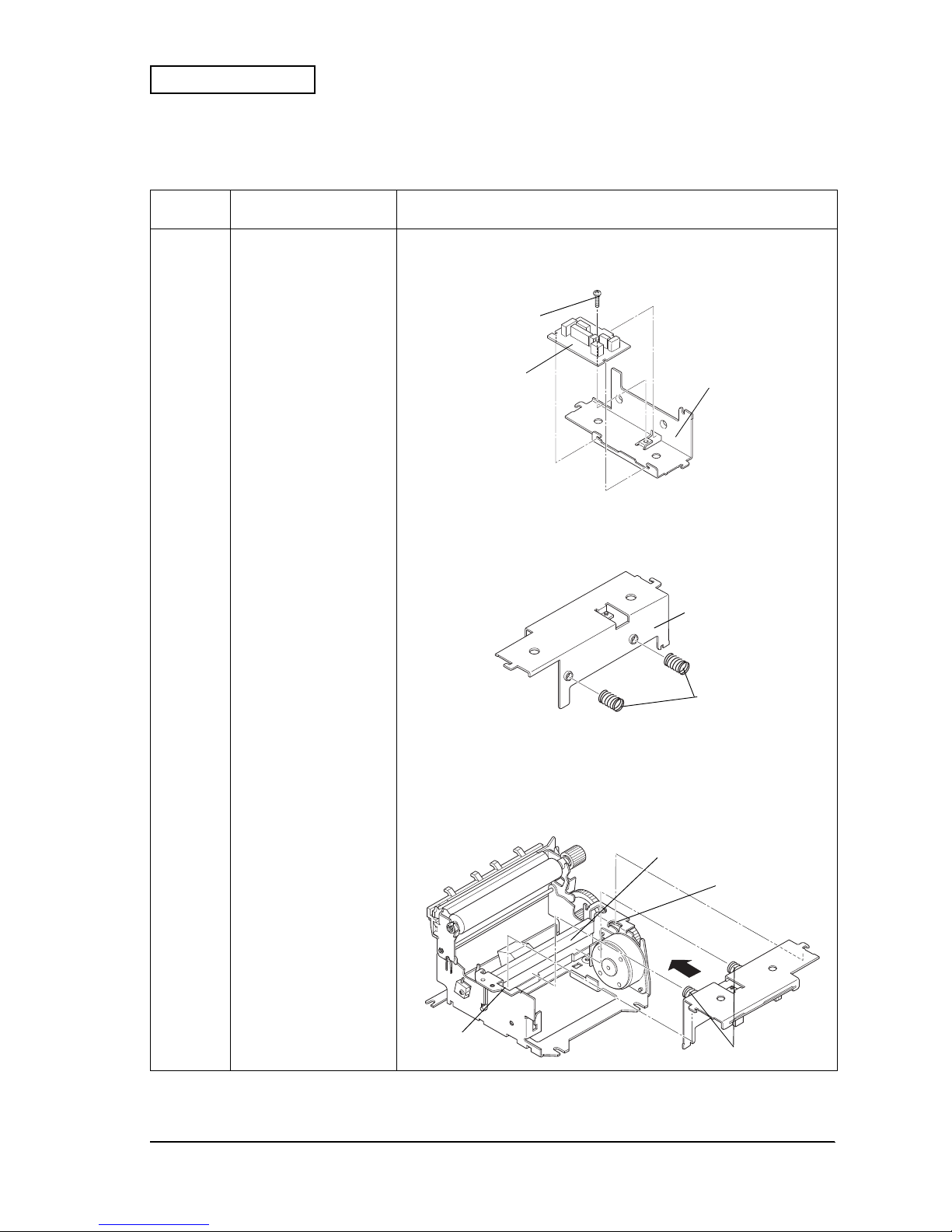
Rev. A Assembly and Disassembly 6-21
EU-T432 Technical Manual
Confidential
Main Assembly E: Plate, pressure spring
Reassembly
step
Part name Assembly procedure
1
Plate, pressure spring
2
Circuit board assembly
C.B.S-tite (M2.5
×
× ×
×
4)
× 1
❏
Install the
circuit board
to the
plate, pressure spring
, and secure it with
screws.
★
<Check>
❏
Tightening torque: 608 to 657 mN•m {6.2 to 6.7 kg•cm}
3
Spring, press head
× 2❏ Install the
spring, press head
to the
plate, pressure spring
.
★
<Check>
❏
Make sure that the
spring, press head
is pushed securely into the
plate,
pressure spring
.
4
❏
Hook the edge of the
spring, press head
to the groove of the
thermal print
head assembly
while pushing the
plate, pressure spring
in the arrow
direction; then hook it to the groove of the
frame assembly
.
plate, pressure spring
C.B.S-tite (M2.5 × 4)
circuit board
assembly
spring, press head
plate, pressure spring
groove of the thermal
print head ass embly
spring, press head
groove of the frame
assembly
groove of the
frame assembly
Page 82

6-22 Assembly and Disassembly Rev. A
Confidential
Main Assembly E
Reassembly
step
Part name Assembly p ro ce d u re
★
<Check>
❏
Make sure that the lead wires, such as those for the
paper detector
assembly
are not caught on anything when installing the
spring, press
head
.
❏
Make sure that the lead wires of the
paper detector assembly
and the
paper detector assembly
are passed under the
plate, pressure spring.
❏
Make sure that the edge of the
spring, press head
fits securely into the
groove on the
thermal print head assembly
.
❏
Make sure that the
plate, pressure spring
is hooked securel y into the hole
on the
frame assembly
.
lead wires
plate, pressure spring
spring, press head
thermal print head
assembly
plate, pressure spring
frame assembly
Page 83

Rev. A Assembly and Disassembly 6-23
EU-T432 Technical Manual
Confidential
Main Assembly F: Fixing plate, the Gear, reduction and G ea r, idler
Reassembly
step
Part name Assembly procedure
1
Fixing plate
C.B.S-tite (M3
×
× ×
×
5)
× 1
❏
Install the
fixing plate
to the
frame assembly
, and secure it with the screw
while pushing the edge of the
fixing plate
to the
bearing, platen
.
★
<Check>
❏
Tightening torque: 834 to 932 mN•m {8.5 to 9.5 kg•cm}
❏
Make sure that the edge of the
fixing plate
is pushed securely to the
bearing, platen
.
2
Gear, reduction
3
Gear, idler
R.E. (2.5)
× 2
❏
Install the
gear, reduction
and the
gear, idler
to the shafts on the
frame
assembly
, and secure th em with
R.E.
s.
★
<Check>
❏
Make sure not to deform the shaft on the
frame assembly
when securing
with the
R.E.
C.B.S-tite (M3 × 5)
bearing, platen
fixing plate
frame assembly
R.E. (2.5)
gear, reduction
gear, idler
frame assembly
shafts
Page 84

6-24 Assembly and Disassembly Rev. A
Confidential
Main Assembly G: Cutter unit
Reassembly
step
Part name Assembly procedure
1
Cutter unit, B
C.B.S-tite (M3
×
× ×
×
5)
× 2
❏
Install the
cutter unit, B
to the
frame assembly
and secure it with screws,
while the
lead wire, paper cutter
is passed through the hook on the
frame
assembly
.
★
<Check>
❏
Tightening torque: 834 to 932 mN•m {8.5 to 9.5 kg•cm}
❏
Make sure that the
lead wire, paper cutter
is passed through the hook on
the
frame assembly
properly as sh own above.
❏
Make sure that the
lead wire, paper cutter
is not caught between any
places when securing the
cutter unit.
❏
Install the
cutter unit, B
in the platen-up state.
②
❏
Lubricate the point where the
fixed blade
of the
cutter unit, B
contacts the
cutter frame
with G-15.
C.B.S-tite (M3 × 5)
frame assembly
lead wire, paper cutter
cutter unit
platen
G-15
G-15
cutter unit, B
Page 85

Rev. A Assembly and Disassembly 6-25
EU-T432 Technical Manual
Confidential
Assembly H: Arranging the lead wires
Reassembly
step
Part name Assembly procedure
1
❏
Insert the lead wire connectors to the connectors on the
circuit board
.
★
<Check>
❏
Make sure that the connectors are oriented properly when connecting.
❏
Make sure that the connectors are inserted securely.
2
❏
All lead wires should be pa ssed through the hook o n th e
frame assembly
,
and arranged inside of th e prin t er.
★
<Check>
❏
Make sure that any of the lead wires are not caught by the projections
(the colored part).
❏
Make sure not to damage the coats of the lead wire s when arr angin g the
lead wires.
variable resistor
connector for the platen detector assembly
connector for the
motor, paper feed,
receipt, B
connector for the
lead wire, paper
cutter
connector for the optional B.M. detector
connector for the paper
detector assembly
hook
projections
Page 86

6-26 Assembly and Disassembly Rev. A
Confidential
Main Assembly I: Cable, printer and Cable, head
Reassembly
step
Part name Assembly pr oc edure
1
Cable, head
❏
Insert the
cable, head
in the connector on the
thermal print head
assembly
.
★
<Check>
❏
Make sure that the
cable, head
is oriented properly when connecting.
❏
Make sure that the
cable, head
is inserted securely
2
Cable, printer
❏
Insert the
cable, printer
in the connector on the
circuit board assembly
.
★
<Check>
❏
Make sure that the
cable, printer
is oriented properly when connecting.
❏
Make sure that the
cable, printer
is inserted securely.
3
❏
Pull out the
cable, head
and the
cable, printer
as shown below.
connector for the
cable, printer
connector for the
cable, head
cable, head
cable, pri n ter
Page 87

Rev. A Assembly and Disassembly 6-27
EU-T432 Technical Manual
Confidential
Assembly J: Black mark detector Adjustment
Adjustment
step
Adjustment procedure Adjustment point
1
❏
Connect the FFC terminal No.12 to an
oscilloscope to display the output power voltage
of the B.M. detector on the oscilloscope screen.
2
❏
Input DC5 V to the FFC termi nal No. 13.
3.
❏
Insert a “Kodak Gray Card” into the pape r
entrance.
(“Kodak Gray Card”: A commercially available
card for adjusting exposure.)
❏
Make sure that the gray side of the card is inserted
along the
paper guide
which the
B.M. detector
sub-assembly
is installed.
4.
❏
Adjust the output power voltage of the
B.M.
detector
at 1.74 V using the variable resistor on
the
circuit board assembly
.
❏
Turn the slot on the variable resistor to the right
and the left wit h a t ool s uch as a f lat -he a d dri ve r,
to adjust the output power voltage.
❏
If the reflectance of black marks on the paper is
over 10%, adjust the output voltage to 2 V or
more with a 25% or less reflectance for the black
marks.
.....13 12 11 10 .....
NO.1
NO.15
circuit board
FFC
oscilloscope
DC5 V
GND
B.M. detector
sub-assembly
gray side of the g r ay ca r d
paper guide
<Cross-section>
variable resistor
Page 88

6-28 Assembly and Disassembly Rev. A
Confidential
Main Assembly K: Cover, cable
Reassembly
step
Part name Assembly procedure
1
❏
Loosen
C.B.S-tite (M3
××××
5)
on the
cutter unit, B
.
2
Cover, cable
❏
Pass the
cable, head
and the
cable printer
through the hole on the
cover, cable
.
3
❏
Attach the
cover, cable
to the mounting position on the
cutter unit, B
, and
tighten
C.B.S-tite (M3
××××
5)
again to secure the
cover, cable
.
★
<Check>
❏
Tightening torque: 834 to 932 mN•m {8.5 to 9.5 kg•cm}
❏❏❏❏
Make sure that the
cover, cable
is attached securely. (
frame, ma i n
)
❏
Make sure that none of the lead wires are caught by any part.
C.B.S-tite (M3 × 5)
cover, cable
cable, printer
cable, head
Page 89
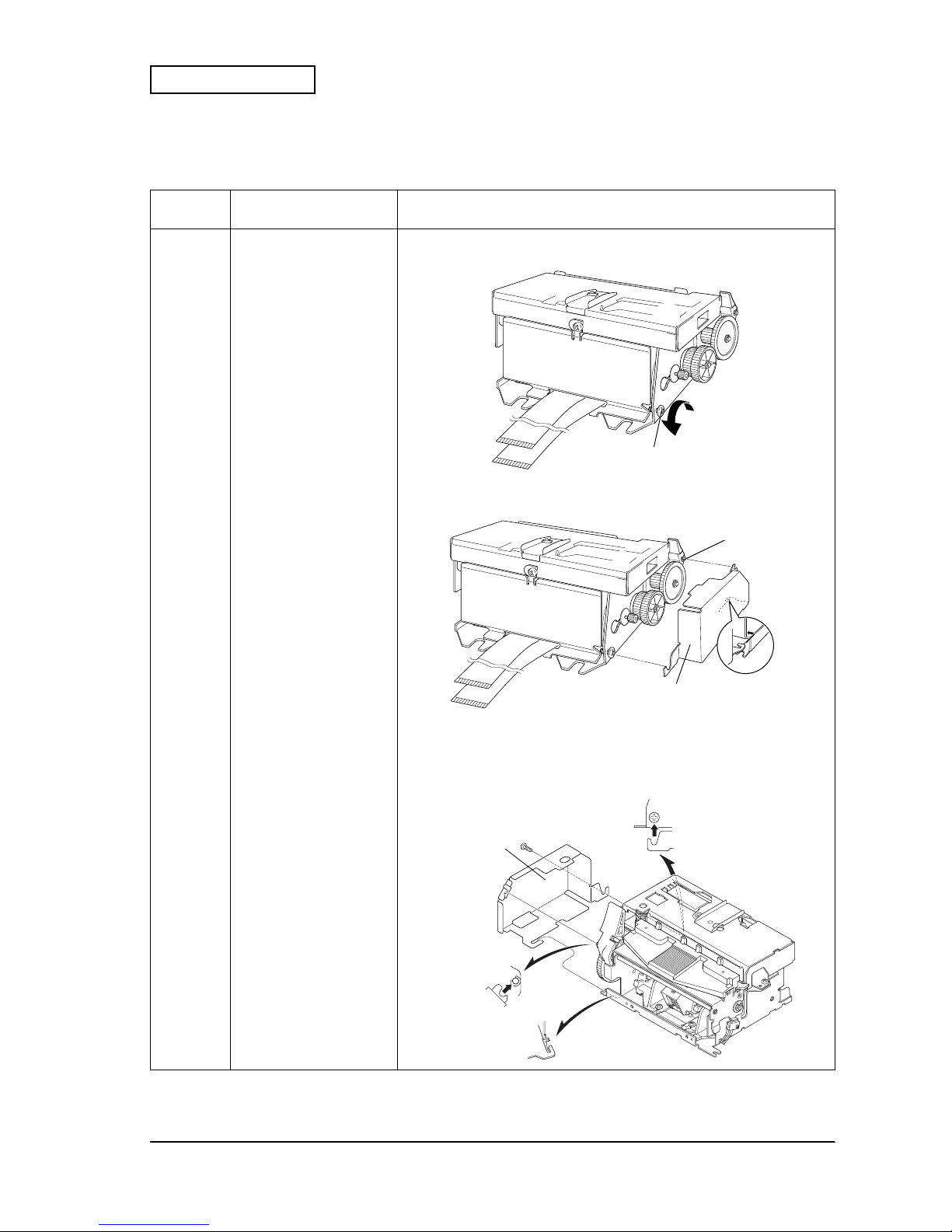
Rev. A Assembly and Disassembly 6-29
EU-T432 Technical Manual
Confidential
Main Assembly L: Cover, gear
Reassembly
step
Part name Assembly procedure
1
❏
Loosen the lower
C.B.S-tite (M3
××××
5)
that secures the
motor, paper feed,
receipt, B
.
2
Cover, gear
❏
Hook the
cover, gear
to the
frame, main
and the
shaft, frame plat en
while
aligning with the mounting positi on s, and secure it.
★
<Check>
❏
Tightening torque: 834 to 932 mN•m {8.5 to 9.5 kg•cm}
❏❏❏❏
The hooking parts on the
cover, gear
are hooked securely to the
frame,
main
.
C.B.S-tite (M3 × 5)
cover, gear
shaft, frame platen
cover, gear
Page 90

6-30 Assembly and Disassembly Rev. A
Confidential
Installation of the Other Modules
Pre-assembly A: Frame, paper supply assembly
Reassembly
step
Part name Assembly procedure
1
Frame, paper supply
assembly
× 1
C.B.S-tite (M3
××××
5)
× 2
❏
Secure the
frame, paper supply assembly
with
C.B.S-tite (M3
××××
5)
.
★
<Check>
❏
Tightening torque: 735 to 931 mN•m {7.5 to 9.5 kg•cm}
2
Damper
× 1❏ Stick the
damper
on the
frame, paper supply assembly
.
★
<Check>
Damper position to stick:
Right and left sides: The center from both sides.
Upper and lower sides: Align with the sticking surface on the plate.
damper
C.B.S-tite (M3 × 5)
frame, paper supply
assembly
Page 91

Rev. A Assembly and Disassembly 6-31
EU-T432 Technical Manual
Confidential
3
C.B (M4
××××
16)
× 1
P. washer (4.3
××××
0.8
××××
8)
× 1
Collar, screw holder
× 1
❏
Attach a
P. washer
(4.3
××××
0.8
××××
8)
and the
collar, screw holder
to a
C.B (M4
××××
16)
screw; then attach the screw to the
frame, paper supply assembly
from out side.
4
Gear, frame open
assembly
× 1
P. washer
(4.3
××××
0.8
××××
8)
× 2
Conical S. washer-1L, 4
× 4
❏
With the flat side of the
gear, frame open assembly
facing to the frame
side, attach it to the
C.B (M4
××××
16)
attached in step 3 from inside of th e
frame, paper supply assembly
; sequently attach a
P. washer
(4.3
××××
0.8
××××
8)
, four
conical S. washer-1L, 4
(with each two of concave surfaces
facing each other), and another
P. washer
(4.3
××××
0.8
××××
8)
to the screw.
5
Plate, rotation stopper
× 1
H. nut (4)
× 1
❏
Attach the
plate, rotation stopper
to the
P. washer
attached in step 4 so
that the bent part of the
plate, rotation stopper
is fit into the square hole
on the
frame, paper supply assembly
; then secure it with an
H. nut.
9
C.B (M4
××××
16)
× 1
P. washer (4.3
××××
0.8
××××
8)
× 3
Collar, screw holder
× 1
Gear, frame open
assembly
× 1
Conical S. washer-1L, 4
× 4
Plate, rotation stopper
× 1
H. nut (4)
× 1
❏
Perform steps 3 to 5 for the other side of the
frame, paper supply
assembly
.
★
<Check>
❏
Tightening torque: 206 to 216 mN•m {2.1 to 2.2 kg•cm}
10
❏
Apply Screw Lock Green (adhesive) to the
H. nut
and the
C.B (M4
××××
16)
.
Reassembly
step
Part name Assembly procedure
hexagonal nut (4)
plate, rotation stoppe r
p. washer (4.3 × 0.8 × 8)
conical S. washer-1L, 4
gear, frame open assemb ly
C.B (M4 × 16)
p. washer (4.3 × 0.8 × 8)
collar, screw holder
frame, paper supply
assembly
square
hole
square hole
Page 92

6-32 Assembly and Disassembly Rev. A
Confidential
11
Power supply connector
assembly
× 1
C.B (M3
××××
4)
× 4
❏
Remove the switch connector from the
power supply connector
assembly
, and insert it to the hole on the
frame, paper supply
. At this
time, the circled mark s ide of th e sw itch connector shou ld be inside.
❏
Pass the lead wires for the power supply connector and the switch
connector under the power circuit board; then attach the
power supply
connector asse mbly
to the
spacer
and secure it with
(C.B (M3
××××
4)
screws. (See the enlarged view below for lead wires.)
★
< Check >
❏
Tightening torque: 539 to 637 mN•m {5.5 to 6.5 kg•cm}
❏
When using an 8 inch roll paper diameter type, pass only the lead wires
for the switch connector under the power circuit board.
12
❏
Insert the
switch connector
into the
power supply connector
.
13
Plate, paper guide, L
× 1
Plate, paper guide, R
× 1
C.B.S-tite (M3
××××
5)
× 2
❏
Attach the
plate, paper guide, L/R
to the
frame, paper supply assembly
and secure them with
C.B.S-tite (M3
××××
5)
screws.
★
< Check >
❏
Installation position of the
plate, paper guide, L/R
:
The outer sides of the
plate, paper guide L/R
’s oval holes are alig ned
with the dowels and the screw holes on the
frame, paper supply
, then
secure the guides while pusing from above.
❏
Tightening torque: 735 to 931 mN•m {7.5 to 9.5 kg•cm}
Reassembly
step
Part name Assembly procedure
Make sure that the lead wires are
passed under the power circuit board
after the power circuit board is
secured with the screws.
plate, paper guide, R
plate, paper guide, L
frame, paper supply
power supply connector
C.B (M3 × 4)
switch
connector
C.B.S-tite (M3 × 5)
C.B.S-tite (M3 × 5)
spacer
screw holes
dowels
Page 93

Rev. A Assembly and Disassembly 6-33
EU-T432 Technical Manual
Confidential
14
Wire band SKB-85
× 2❏ Pass the lead wires for the
power supply connector
through the square
hole on the
frame, paper supply
and secure them with wire bands at
two places.
★
< Check >
❏
The lead wires for the upper fastening position should be arranged
behind the bent part of the frame.
Reassembly
step
Part name Assembly procedure
square hole
wire bands SKB-85
Page 94

6-34 Assembly and Disassembly Rev. A
Confidential
Pre-assembly B: Roll paper holder unit
Reassembly
step
Part name Assembly procedure
1
Roll paper holder
reinforcement assembly
× 1
Spring, open lever
× 1
❏
Attach the
spring, open lever
to the convex parts on the
frame, open
lever
on the
roll paper holder reinforcement assembly
.
★
< Check >
❏
Make sure to confirm that the
lever, open
operates properly.
2
C.B.S-tite (M3
××××
5)
× 1❏ Attach the
roll paper holder reinforcement assembly
to the
frame, roll
paper holder assembly
, and secure it with a
C.B.S-tite (M3
××××
5)
screw.
★
< Check >
❏
Tightening torque: 735 to 931 mN•m {7.5 to 9.5 kg•cm}
3
Gear, frame opening and
shutting
× 1
P. washer
(3
××××
0.5
××××
7)
× 1
H. nut (3)
× 1
C.F (3
××××
8)
× 1
❏
Align the
gear, frame opening and shutting
with the dowels on the
frame,
roll paper holder
from inside, and att ach a
C.F (3
××××
8)
screw to it from the
outside. Secure the
gear, frame opening and shutting
with an
H. nut (3)
via a
P. washer (3.2
××××
0.5
××××
7)
.
★
< Check >
❏
Tightening torque: 539 to 637 mN•m {5.5 to 6.5 kg•cm}
4
Gear, frame opening and
shutting
× 1
P. washer
(3
××××
0.5
××××
7)
× 1
H. nut (3)
× 1
C.F (3
××××
8)
× 1
❏
Perform steps 2 and 3 for the other side of the
frame, roll paper holder
assembly
.
★
< Check >
❏
Tightening torque: 539 to 637 mN•m {5.5 to 6.5 kg•cm}
plate, reinforcement
spring, open lever
frame, open lever
roll paper holder
reinforcement assembly
frame, roll paper
holder assembly
C.F (3 × 8)
H. nut (3)
P. washer (3 × 0.5 × 7)
gear, frame opening
and shutting
C.B.S-tite (M3 × 5)
Page 95

Rev. A Assembly and Disassembly 6-35
EU-T432 Technical Manual
Confidential
5
NE detector assembly
× 1
Lead wire, NE detector
× 1
❏
Connect th e
lead wires, NE detector
to the
NE detector assembly.NE
.
6
Cover, NE detector
× 1
Wire band, SKB-85
× 1
❏
Attach the
NE detector assembly
to the
cover, NE de te ct or
away from the
side with a screw hole.; then fasten the lead wires with a
wire band
.
★
< Check >
❏
The fastening part should be under the bent part on the cover.
7
C.B.S-tite (M3
××××
5)
× 1❏ Attach the
NE detector assembly
to the
frame, roll paper holder
aligning
the dowels on the
NE detector assembly
with the grooves on the frame;
then secure the
cover, NE detector
with the
NE detector assembl y
to the
frame, roll paper holder
with a
C.B.S-tite (M3
××××
5)
screw.
★
< Check >
❏
Tightening torque: 735 to 931mN•m {7.5 to 9.5 kg•cm}
❏
NE detector mounting pos ition: 6 inch type; lowe r, and 8 inch type; upper
8
C.B.S-tite (M3
××××
5)
× 1
❏
Align the center of the
NE detector
's dowel at A on the scale gradation;
then secure the
NE detector
with a
C.B.S-tite (M3
××××
5)
screw.
(A: Default setting)
★
< Check >
❏
Tightening torque: 735 to 931mN•m {7.5 to 9.5 kg•cm}
Reassembly
step
Part name Assembly procedure
cover, NE detector
NE detector assembly
screw hole
lead wire, NE detector
wire band SKB-85
cover, NE detector
frame, roll paper holder
groove for 8 inch type
for 6 inch type
C.B.S-tite (M3 × 5)
(for NE detector)
groove for 8 inch type
groove for 6 inch type
A
for 8 inch type
C.B.S-tite (M3 × 5)
(for cover, NE detector)
groove for
6 inch type
dowel
dowel on the rear side
of the NE detector
assembly
Page 96

6-36 Assembly and Disassembly Rev. A
Confidential
9
Roll paper holder R
assembly
(for a 6 inch
paper roll diameter) × 1
or
Roll paper holder R
assembly, B (for a 8 inch
paper roll diameter)
× 1
Spring, roll paper holder
× 2
❏
Attach the
spring, roll paper holder
to the
roll paper holder R assembly
(or
roll paper holder R assembly, B
).
10
Roll paper holder R
assembly
(Roll paper holder R
assembly, B)
× 1
C.B (M3
××××
8)
× 2
❏
Align two dowels A on the
roll paper holder, R assembly
with the square
holes A from the inside of the
frame, roll paper holder
; then secure the
assembly with
C. B (M3 x 8)
screws from the outside. (The dowels and
square holes B for the
roll paper holder R assembly, B
)
★
< Check >
❏
Tightening torque: 539 to 637 mN•m {5.5 to 6.5 kg•cm}
Reassembly
step
Part name Assembly procedure
roll paper holder, R
assembly (for 6 inch type)
spring, roll paper holder
spring, roll paper holder
roll paper holder, R
assembly, B (for 8 inch type
dowels B
dowel s A
square holes A
square holes B
C.B (M3 × 8)
(mounting position for
8 inch type)
C.B (M3 × 8)
(mounting position for
6 inch type)
frame, roll paper
holder
Page 97

Rev. A Assembly and Disassembly 6-37
EU-T432 Technical Manual
Confidential
11
Roll paper holder L
assembly
(for a 6 inch
paper roll diameter) × 1
or
Roll paper holder L ass embly,
B (for a 8 inch paper roll
diameter)
× 1
Spring, roll paper holder
× 2
❏
Attach the
spring, roll paper holder
to the
roll paper holder L assembly
(or
roll paper holder L assembly, B
).
★
< Check >
❏
Tightening torque: 539 to 637 mN•m {5.5 to 6.5 kg•cm}
12
Roll paper holder L
assembly
(Roll paper holder L
assembly, B)
× 1
C.B (M3
×
× ×
×
8)
× 2
❏
Align three dowels C on the
roll paper holder, L assembly
with the square
holes and the notch C on the frame and the
cover, NE detector
from the
inside of the
frame, roll paper holder
; then secure the assembly with
C.B
(M3
×
× ×
×
8)
screws from the outside. (The dowels, holes and notch D for the
roll paper holder, L assembly, B
)
★
< Check >
❏
Tightening torque: 539 to 637 mN•m {5.5 to 6.5 kg•cm}
Reassembly
step
Part name Assembly procedure
C.B (M3 × 8)
(mounting position for
8 inch type)
square hole C
C.B (M3 × 8)
(mounting position for
6 inch type)
dowel D
square hole and notch
C and D (common)
roll paper holder, L
assembly (for 6 in c h ty pe)
roll paper holder, L assembly, B
(for 8 inch type)
dowels C
dowels D
spring, roll paper holder
note:
In this illustration, the roll p ap er
holder R assembly is att a c hed to
the frame, roll paper holder.
Page 98

6-38 Assembly and Disassembly Rev. A
Confidential
13
Wire band SKB-85
× 3 ❏ Fasten the
lead wire, NE detector
to the frame with the
wire band SKB-85
at three points.
14 ❏ Take out the connector of the
lead wire, NE detector
trough the round
hole on the frame.
★
< Check >
❏ The fastening part should be under the cover.
Reassembly
step
Part name Assembly procedure
wire band SKB-85
round hole
lead wire, NE detector
fastening part
Page 99

Rev. A Assembly and Disassembly 6-39
EU-T432 Technical Manual
Confidential
Pre-assembly C: Roll paper supply module
Reassembly
step
Part name Assembly procedure
1
frame, paper supply unit
× 1
Roll paper holder unit
× 1
❏
Place the
frame, paper supply unit
on the
roll paper holder unit
aligning
the hole positions.
2
Collar, screw holder
× 1
❏
Attach the
collar, screw holder
to the screw hole on the frame from
outside.
3
C.B (M4
××××
16)
× 1
S. washer-2, 4
× 1
Plate, rotation stopper
assembly
× 1
❏
Attach a
S. washer
and the
plate rotation stopper assembly
to a
C. B (M4
x 16)
screw, and fit it into the
collar, screw holder
on the frame from
outside so that the bent part on the
plate, rotation stopper assembly
is fit
in the square hole on the frame.
4
P. washer (4.3
××××
0.8
××××
8)
× 1
H. nut (4)
× 1
❏
Attach a
P. washer (4.3 x 0.8 x 8)
from inside of the frame, then secure it
with an
H. nut (4)
.
★
< Check >
❏
Tightening torque: 441 to 539 mN•m {4.5 to 5.5 kg•cm}
5
Collar, screw holder
×
1
C.B (M4
××××
16)
×
1
S. washer-2, 4
×
1
Plate, rotation sto pp er
assembly
×
1
P. washer (4.3
××××
0.8
××××
8)
×
1
H. nut (4)
×
1
❏
Perform the same steps for t h e other side.
★
< Check >
❏
Tightening torque: 441 to 539 mN•m {4.5 to 5.5 kg•cm}
6
❏
Lubricate the
H.nut (4)
and the screw part with screw lock.
plate, rotation stoppe r
assembly
C.B (M4 × 16)
S. washer-2, 4
collar, screw holder
P. washer (4.3 × 0.8 × 8)
H. nut (4)
roll paper holder unit
frame, paper
supply unit
square hole
square hole
Page 100

6-40 Assembly and Disassembly Rev. A
Confidential
Pre-assembly D: Presenter tab l e assembly
Reassembly
step
Part name Assembly procedure
1
Table, presenter
× 1
P. washer (4
××××
0.8
××××
10)
× 1
C.B.P-tite (M3
××××
8)
× 1
❏
Attach the
circuit board
to the
table, presenter
and secure it with a
C.B.P-
tite (M3
××××
8)
screw via a
P. washer
.
★
< Check >
❏
Tightening torque: 735 to 931 mN•m {7.5 to 9.5 kg•cm}
2
Paper detector, assembly 1
× 1
❏
Slide the
paper detector, assembly 1
(with a large lever) into the snap
fastener on the the
circuit board
side.
★
< Check >
❏
Make sure that the
paper detector, assembly 1
is fit securely in to th e sna p
fasteners .
3
Paper detector assembly
×1❏ Slide the
paper detector assembly
(with a small lever) to the other snap
fastener.
★
< Check >
❏
Make sure that the
paper detector assembly
is fit securely into the snap
fasteners.
❏
Make sure the correct mounting position for the
paper detector,
assembly 1
and the
paper detector assembly
to attach.
circuit board assembly
C.B.P-tite (M3 × 8)
paper detector, assembly 1
paper detector
assembly
table, presenter
P. washer (4 × 0.8 × 10)
snap fasteners
 Loading...