

Page 1

®
EPSON
Equity™ I
User’s Guide
Page 2

IMPORTANT NOTICE
DISCLAIMER OF WARRANTY
Epson Corporation makes no representations or warranties, either express or
implied, by or with respect to anything in this manual, and shall not be liable
for any implied warranties of merchantability and fitness for a particular purpose or for any indirect, special or consequential damages. Some states do not
allow the exclusion of incidental or consequential damages, so this exclusion
may not apply to you.
COPYRIGHT NOTICE
All rights reserved. No part of this publication may be reproduced, stored in a
retrieval system, or transmitted, in any form or by any means, electronic,
mechanical, photocopying, recording or otherwise, without the prior written
permission of Epson Corporation No patent liability is assumed with respect to
the use of information contained herein. While every precaution has been
taken in the preparation of this publication, Epson Corporation assumes no
responsibility for errors or omissions. Nor is any liability assumed for dam-
ages resulting from the use of the information contained herein. Further, this
publication and features described herein are subject to change without notice.
TRADEMARKS
Epson is a registered trademark of Epson Corporation.
Equity is a trademark of Epson America, Inc.
IBM and IBM-PC are registered trademarks of International Business
Machines Corp.
MS-DOS and GW-BASIC are trademarks of Microsoft Corp.
CP/M and CP/M-86 are registered trademarks of Digital Research Inc.
Copyright © 1985 by Epson Corporation
Nagano, Japan
Q50185001-0
Page 3

FCC COMPLIANCE STATEMENT
FOR AMERICAN USERS
This equipment generates and uses radio frequency energy and if not installed and
used properly, that is, in strict accordance with the manufacturer’s instructions,
may cause interference to radio and television reception. It has been type tested
and found to comply with the limits for a Class B computing device in accordance
with the specifications in Subpart J of Part 15 of FCC rules, which are designed to
provide reasonable protection against such interference in a residential installa-
tion. However, there is no guarantee that interference will not occur in a particular
installation. If this equipment does cause interference to radio or television recep-
tion, which can be determined by turning the equipment off and on, the user is
encouraged to try to correct the interference by one or more of the following measures:
. Reorient the receiving antenna
l
Relocate the computer with respect to the receiver
l
Move the computer away from the receiver
l
Plug the computer into a different outlet so that computer and receiver are on
different branch circuits.
If necessary, the user should consult the dealer or an experienced radio/television
technician for additional suggestions. The user may find the following booklet
prepared by the Federal Communications Commission helpful:
“How To Identify and Resolve Radio-TV Interference Problems”
This booklet is available from the U.S. Government Printing Office, Washington
DC 20402. Stock No. 004-000-00345-4.
Note: If the interference stops, it was probably caused by the computer or its
peripheral devices. To further isolate the problem:
Disconnect the peripheral devices and their input/output cables one at a
time. If the interference stops, it is caused by either the peripheral device or
its I/O cable. These devices usually require shielded I/O cables. For Epson
peripheral devices, you can obtain the proper shielded cable from your
dealer. For non-Epson peripheral devices contact the manufacturer or
dealer for assistance.
WARNING
This equipment has been certified to comply with the limits for a Class B computing device, pursuant to Subpart J of Part 15 of FCC Rules. Only peripherals (computer input/output devices, terminals, printers, etc.) certified to comply with the
Class B limits may be attached to this computer. Operation with non-certified
peripherals is likely to result in interference to radio and TV reception.
The connection of a non-shielded equipment interface cable to this equipment will
invalidate the FCC Certification of this device and may cause interference levels
which exceed the limits established by the FCC for this equipment.
. . .
111
Page 4

Page 5

Contents
Introduction . . . . . . . . . . . . . . . . . . . . . . . . . . . . . . . . . .
How to use this manual
Setting Up Your System
Unpacking
Choosing a Location
Arranging the Components
The Rear Panel
The Front Panel
Removing the disk drive protector sheets
Connecting the Components
Connecting the Video Monitor
Connecting the Keyboard
Special keys
Connecting your Printer
Parallel interface
Serial interface
Using Epson printers with the Equity
special character set
Dip Switches Settings
Dip switch functions
...................................
................................
...............................
................................
..............................
. . . . . . . . . . . . . . . . . . . . . . . .
........................
...........................
.....................
........
....................
...................
.......................
........................
............................
..........................
..........................
.........................
1
2
3
3
4
5
6
7
9
11
11
12
14
15
15
17
17
18
18
Using your Equity
Powering Up
The initial screen display
Inserting and Removing Disks
Resetting the Computer
Using Disks
How Disks Work
Choosing Floppy Disks for the Equity
Taking Care of your Disk and Disk Drives
Protecting your Data
Write-protecting floppy disks
Making backup copies
Using a Single Floppy Disk Drive
Using a Hard Disk Drive . . . . . . . . . . . . . . . . . . . . . . . .
.............................
.................................
......................
...................
.........................
..................................
..............................
.............
.........
...........................
..................
.......................
................
21
21
22
23
24
25
25
26
26
27
28
28
29
29
V
Page 6

Using Option Cards
5
Installing an Option Card
Removing the cover
Inserting the option card
Removing an access slot cover
Replacing the cover
Removing option cards
Installing Memory Expansion Cards
Using a mouse
............................
..........................
..........................
..............................
Appendixes
.......................
......................
.................
.......................
..............
31
31
31
33
35
35
36
36
38
A
Troubleshooting
The Computer Fails to Start Up
The Video Display Does Not Appear
The Computer Hangs Up or Freezes
Floppy Disk Problems
Software Problems
Printer Problems
Option Card Problems
Hard Disk Problems
Specifications
B
CPU and Memory
Controllers
Interfaces
Power Supply
Mass Storage
Keyboard
Environmental Requirements
Physical Characteristics (CPU only)
Power Requirements
...............................
..........................
............................
..............................
.........................
...........................
.................................
.............................
...................................
....................................
.................................
.................................
....................................
...........................
..................
.............
..............
....................
..............
A-1
A-1
A-1
A-2
A-2
A-3
A-3
A-4
A-4
B-1
B-1
B-1
B-1
B-2
B-2
B-2
B-2
B-2
B-2
C Glossary
Index . . . . . . . . . . . . . . . . . . . . . . . . . . . . . . . . . . . . . . . .
vi
.....................................
C-1
Index-1
Page 7

Figures
1-1
System arrangement
1-2
Rear panel
1-3
Front panel
Connecting the monitor cable
2-l
Keyboard cable connection
2-2
Adjusting the keyboard legs
2-3
Special keys
2-4
Printer placement
2-5
Printer connection
2-6
Location of DIP switches
2-7
DIP switch functions
2-8
Inserting disks
3-l
4-l
Write-protect notch . . . . . . . . . . . . . . . . . . . . . . . . . . . .
5-l
Back panel screws
5-2
Side screws under plastic inserts
5-3
Removing cover
5-4 Option card installation
5-5
Removing access slot cover
5-6 Memory expansion connector
...................................
...................................
..................................
...........................
....................
......................
.....................
..............................
.............................
.......................
...........................
. . . . . . . . . . . . . . . . . . . . . . . . . . . . . . . .
.............................
..................
...............................
........................
......................
...................
5
6
8
12
13
14
14
16
17
18
19
23
28
32
32
33
34
35
37
vii
Page 8

Introduction
Your Epson® Equity’” personal computer is a versatile, expandable,
and economical system which offers you a wide variety of choices. Its
flexibility lets you create your own system; first you choose from three
models of the Equity main unit, then you select the accessories you want
to use with it to assemble the configuration that does the most for you.
The Equity main unit (CPU) is available in three configurations:
One floppy disk drive
l
Two floppy disk drives
l
One floppy disk drive and one internal hard disk drive.
l
You also choose which monitor you want to use.
Optional cards and external devices further expand the capabilities
of your Equity. Its built-in serial and parallel interfaces let you connect
virtually any peripheral device you choose. Here are a few of the devices
that you can use with your system:
l Memory expansion card
Mouse and mouse interface card
l
l Monochrome video card
l Monochrome monitor
l Color/graphics video card
RGB color monitor.
l
And you can connect your Equity to any one of
16 Epson printers.
Check with your Epson dealer from time to time to find out which
external devices and option cards are available. You can use most of the
cards designed for the IBM@ personal computer on your Equity.
Page 9

How to Use this Manual
This user’s guide provides the basic information you need to set up
and care for your Equity. It also describes how to connect optional equipment and start using your operating system. Although this book con-
tains a lot of information, it won’t take you long to set up your system
and get started.
Follow the instructions in Chapter 1 to unpack and set up your sys-
tem. Then connect the various components as Chapter 2 describes.
Chapter 3 tells you how to turn on your Equity and describes some
of the general operational procedures. Chapter 4 contains information
on disks which you should read to gain a general understanding of how
they work, and Chapter 5 explains how to install and remove option
cards.
The appendixes provide additional information on troubleshooting,
hardware specifications, and a glossary of some of the computer terms
this book uses. Refer to the glossary whenever you come across an unfamiliar word. You may even want to glance through it before you start
reading.
You do not need to read everything in this book; some sections
describe a particular option or accessory you may not have.
The Equity comes with the MS-DOS operating system and
GW’“-BASIC.
Although this manual explains how to load your software disks, refer to
the manuals that come with your software applications to learn how to
use them.
If you have used MS-DOS before on another computer, you will find
that it works the same on your Equity. You may want to refer to your
Equity MS-DOS manual, however, for the special menu utilities added
by Epson.
You may have purchased other software as well.
Page 10

Chapter 1
Setting Up Your System
It won’t take you long to get your Epson Equity personal computer
up and running. This chapter shows you how to set up the computer and
peripherals and make any necessary adjustments.
Unpacking
When you unpack your Equity, you should find the following items:
The main unit and power cord
The keyboard with cable
An MS-DOS operating system disk with an MS-DOS manual
A GW-BASIC programming language disk with a GW-BASIC
manual
This Equity I User’s Guide.
In addition to these items, you may have purchased one of the following
video monitors:
l
Epson monochrome monitor MBM-2095-E and monochrome video
card
l
Epson RGB color monitor MCM-4035N-E and color/graphics video
card
l
Any other compatible video monitor and appropriate video card.
After you remove the components from their cartons, be sure to
inspect each unit. If anything is missing, looks damaged, or seems
wrong, consult your Epson dealer.
You’ll find two registration cards: one with the main unit and one
with the keyboard. Fill these cards out now and mail them to Epson.
With your registration cards on file, Epson can continue to support your
hardware and software.
Don’t throw away your packing materials. They are designed to provide the best protection possible, and you may need them later, whenever you move or ship your system.
3
Page 11

Choosing a Location
An important part of setting up your Equity is deciding where to
locate it. Whether you use your computer at home or in the office, you
want to choose a comfortable, convenient location.
Before you set up your system, be sure the location you’ve selected
provides the following:
A large, sturdy desk or table. Make sure the surface you select for
your system is sturdy enough to easily support the weight of all its
components.
A flat, hard surface. Soft surfaces like beds and carpeted floors
attract static electricity, which can actually erase data from your
disks and cause problems in the computer’s circuitry. Soft surfaces
also interfere with proper ventilation.
Good air circulation. Air must be able to circulate freely under the
system as well as behind it. Leave several inches behind the computer
clear to allow ventilation.
Moderate environmental conditions. It’s important to protect your
computer from extremes in temperature, humidity, dust, and smoke.
Avoid direct sunlight or any other type of heat source. Don’t use
your Equity in damp areas-excessive humidity can hinder operation. Dust and smoke are especially damaging to the the magnetic
surfaces of your disks and to the heads in your disk drives (which can
damage the data on your disks).
Appropriate power source. To prevent static charges, connect all
your equipment to 3-prong, 120-volt grounded outlets. You need
one outlet for the computer main unit, one for the video monitor,
and additional outlets for your printer and other peripheral devices.
Freedom from electromagnetic interference. Keep your computer
away from any electrical device that can generate an electromagnetic
field. Surprisingly, even your telephone can cause trouble, especially
if you keep your diskettes right next to it.
Once you’ve found the ideal location for your Equity, you’re ready
to set up your system.
Page 12
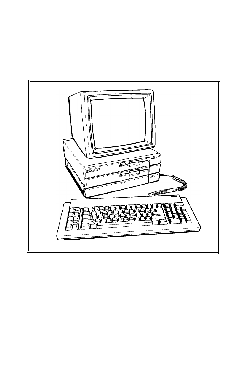
Arranging the Components
First decide how you want to arrange the different parts of your sys-
tem. The most common setup, shown in Figure l-l, is to lay the main
unit flat and set the video monitor on top of it with the keyboard directly
in front (leaving enough space to insert disks into the disk drives).
Figure 1-1. System arrangement
Of course, if you have special computer furniture or want to customize your setup, you can arrange your Equity components to suit your
own particular needs.
5
Page 13

The Rear Panel
Before you connect your system components, take a quick look at
the rear panel to familiarize yourself with the locations of the various
Equity input/output ports. Figure 1-2 shows where you connect the various peripheral devices.
WARNING: Do not connect the power cord until you have connected
all peripheral devices. Once you connect the power cord,
always check to see that the power switch is OFF whenever
you connect or disconnect any peripheral devices.
AC
\
Power cord
Pareiiel port
\
RS-23k
serial port
Figure 1-2. Rear panel
Option card
access slots
Page 14

Here are brief descriptions of each of the ports:
AC outlet. Auxiliary power outlet. Power consumption should not
exceed 65 watts.
Power cord. Supplies electrical power to the computer. Always turn
the power switch OFF before you plug the power cord into an outlet.
RS-232C serial port. Allows you to connect an external device with a
serial interface, such as a modem, another computer or a printer
with a serial interface.
Parallel printer port. Allows you to connect an external device that
uses a parallel interface, such as a printer or plotter.
Option card access slots. The Equity has space for three option cards
(which control your peripherals). One of these slots is always occupied by either your monochrome or color/graphics video card. You
can use the other two to add special devices such as a mouse card or
hard disk controller. You do not need to use any of the option slots to
add extra memory.
The Front Panel
Now take a look at the front panel. The components on the front
panel are shown in Figure 1-3 with the covers open to reveal the switches
and the keyboard cable socket. To open each cover, press down gently
on the small handle.
Page 15

Disk lock/release button
Disk drive
LED lamps
Power LED lamp
Optional
disk drive RESET
slot
/
/
button
\ \
DIP switches
Keyboard
cable socket
Figure 1-3. Front panel
The front panel components work as follows:
Disk lock/release button. Press to lock a diskette in place. Press
again to eject it.
Disk drive LED lamps. A red light indicates that the drive is being
accessed.
Slot for optional disk drives, You can insert a second floppy disk
drive or a hard disk drive in this optional slot. All Equity units come
with at least one floppy disk drive. The main unit above is shown
with a second floppy disk drive.
Power LED lamp. A red light indicates the power is ON.
Power switch. Turns the main unit ON and OFF.
Keyboard cable socket. The keyboard plugs into the main unit here.
RESET button. Resets the main unit. When an operating system disk
is in the top drive, you can press the reset button to start it.
DIP switches. These tell the computer its memory size, monitor
type, number of floppy disk drives, and interface types. You set them
to match your system requirements.
Page 16

Removing the disk drive protector sheets
A cardboard sheet occupies the disk slot in the floppy-disk drive.
This sheet is inserted at the factory to protect the recording heads.
Remove the sheet before you connect any cable. Press the button
labelled PUSH on the left side of the drive. The button pops out when
you press it, along with the edge of the protector sheet. Carefully pull out
this sheet.
Save the protector sheet and reinsert it whenever you move the computer, even if you are just moving it to another part of the room. If you
are not going to use your computer for a week or more, such as when
you go on vacation, reinsert the protector sheet to help keep dust from
entering the disk drive.
Page 17

Chapter 2
Connecting the Components
Once you set up the various components of your system, you need
to connect the necessary cables. If you follow the instructions and refer
to the figures in this section, you should have no trouble.
Connecting the Video Monitor
The video monitor should be on top of or near the Equity main unit.
It is easier to connect the cable if the back of the monitor and the main
unit are facing you. This may not be possible, however, if your system is
set up on computer furniture.
The exact procedure for connecting your monitor depends on the
model you have. Refer to your monitor manual for detailed instructions.
Here are some basic guidelines for connecting your video monitor to the
Equity main unit:
1. If necessary, connect the video monitor cable to your monitor. Some
cables are permanently attached to the monitor at one end.
2. Connect the appropriate end of the video monitor cable to your
monochrome or color/graphics card connector at the back of the
main unit. If the plug has retaining screws, tighten them with a screw
driver.
The monitor type must match the video card in the main unit. If you
have a color card, there are two types of connectors provided-a
nine-pin female D-connector for RGB monitors and an RCA connector for composite video monitors.
3. Plug the monitor power cable into an electrical outlet.
Note: Many monochrome monitors can be plugged into the auxil-
iary outlet at the back of the main unit provided the plug fits
into the outlet and the monitor’s power consumption does not
exceed 65 watts.
11
Page 18

Figure
2-l
gives you an idea of how to connect the monitor,
Figure 2-1. Connecting the monitor cable
4. When you check the DIP switch settings later in this chapter, be sure
they are set correctly for the type of monitor you have.
5. If you have trouble getting a display, check that the brightness and
contrast controls on the monitor are set correctly. Monitors usually
have their own power switch. Make sure it is ON.
Connecting the Keyboard
Once your Equity main unit and video monitor are connected, you
can connect the keyboard. The keyboard cable is coiled like a telephone
cord with the connector on one end.
12
Page 19
With the front of the main unit facing you, open the cover at the lower
right front corner. Insert the keyboard connector as shown in Figure 2-2.
Do not force the connector, but make sure you insert it all the way See
that the cable exits to the right of the main unit. Gently push the cable
into the retaining clip, and close the cover.
Figure 2-2. Keyboard cable connection
You can use the keyboard at different angles such as laying it flat on a
desk or placing it on your lap. You can also tilt the keyboard by adjusting
the legs on the bottom. Adjust the keyboard legs by turning the keyboard over, reaching under the lip and lifting each of the legs upward
until they lock into place. See Figure
2-3.
13
Page 20

Figure 2-3. Adjusting the keyboard legs
To disconnect the keyboard, open the cover on the main unit and
press down on the retaining clip to release the cable. Lift the tab on the
connector, and pull it straight out from the main unit.
Special keys
The dark gray keys have special functions and are used in various
ways by applications programs. Some of the more important keys are
shown in Figure 2-4 and described below:
14
Figure 2-4. Special keys
Page 21

Key
I+
-4
Purpose
Moves the cursor to the right in normal mode
and to the left in Shift mode. Referred to as the
tab key.
Ctrl
Alt
Shift
Caps Lock
Num Lock
Enter
t
Works with others keys to perform special (con-
trol) functions such as editing functions in
MS-DOS and GW-BASIC.
Lets you input alternate character codes not otherwise available.
Produces uppercase characters or symbols when
used with the main character keys. Produces
lowercase characters if Caps Lock is on.
Changes the letter keys from lower- to upper-
case; changes back to lowercase when pressed
again.
Changes the function of the numeric/cursor
keys from numeric to cursor; changes back
when pressed again.
Ends a line of keyboard input.
Moves the cursor back one space, deleting the
character to the left. Referred to as the backspace key.
Connecting your Printer
Your Equity has serial and parallel interfaces built-in. You can easily
connect a printer or plotter that has either a serial or parallel interface.
Parallel interface
The parallel connector on the Equity is a Centronics compatible con-
nector but uses a
on many other computers. Most Epson printers have a parallel interface.
DB-25
socket, the same type as the
RS-232C
serial port
15
Page 22

To connect your printer to a parallel interface:
1.
Place the printer in a convenient location next to your system so that
the power and data cables do not interfere with the paper. See Figure
2-5.
Figure 2-5. Printer placement
2.
Before connecting any cables, make sure the power switches to both
the main unit and the monitor are switched OFF. If you are not sure
which cable you need, consult your dealer.
3.
One end of the printer cable has a 25-pin male D-connector. (Refer to
your printer manual to determine which end this is.) Connect this
end to the socket marked PARALLEL on the back panel of the main
unit. If the plug has retaining screws, tighten them with a small
screwdriver.
4.
Connect the other end of the cable to the printer. Secure the cable by
placing the squeeze locks at each side of the printer port into the
connectors on each side of the cable. See Figure 2-6.
16
Page 23

Figure 2-6. Printer connection
5. Plug the printer’s power cable into a separate electrical outlet.
Serial Interface
If you have a device, such as a modem, that has a serial interface,
connect it to the port marked SERIAL at the back of the main unit. If
your cable is the non-standard type, with a male D-connector at both
ends, you need an adapter to connect it to the computer. To connect your
serial device, follow the same steps above for connecting a parallel
device.
The RS-232C serial port needs to be configured properly in order for
it to function correctly. The printer output must also be redirected to the
SERIAL port, instead of the PARALLEL port. Use the MS-DOS SETUP
utility (or the MODE command in the SETUP utility) to make these
changes. See your MS-DOS manual for instructions on how to use these
commands.
Using Epson printers with the Equity special character set
The Equity uses a special character set that assigns graphics and
international characters to some of the ASCII codes. In most cases, if you
try to print these characters on a standard printer, you get italic characters instead. Many Epson printers support the IBM character set (like
those used on the Equity) as a standard feature, and other printers can be
adapted. In addition, some applications programs print the special
graphics characters on a standard printer using a special printer driver
program. Ask your dealer for more information.
17
Page 24

DIP Switch Settings
When you first turn on your system, it checks the DIP switch settings
to determine the memory size, the monitor type, the number of floppy
disk drives, and the built-in interfaces being used.
Your dealer should have set these switches for you. However, read
the descriptions carefully and make sure the switches are set to meet your
system requirements. If you upgrade your system at a later date-by
adding a second disk drive for example-you may need to alter the
switch settings.
Note: Set the DIP switches with the power OFF because software pro-
grams check the settings only when you turn on the system.
Incorrect settings do not damage your computer, but a program
may not operate properly if it finds the settings do not match the
hardware.
The DIP switches are located underneath the cover below the floppy
disk drive on the front panel of your main unit, as shown in Figure 2-7.
Open the cover.
Figure 2-7. Location of DIP switches
Notice the switches are numbered from 1 to 10. When a switch is Up
it is ON. When the switch is DOWN, it is OFF. To change the switch
settings, use a hard, thin object, such as a small screwdriver or the back
of a ballpoint pen.
18
Page 25

DIP switch functions
Inside the DIP switch cover is a label that identifies each of the DIP
switches and shows the different ways they can be set (see Figure 2-8).
The paragraphs below describe the various possible settings for your
DIP switches.
DIP SWITCH !%TTlNG
SWITCH
II
RAM
SIZE
MONITOR
256
KB
512
KB
OTHERS
MONOCHROME
COLOR@0 x
COLOR(40 x
251
251
1234567
ON
OFFOFF
ON
-
- -
ON ON -
OFFOFF
OFF ON -
Refer 10 Table 2-1
- - ON OFF SERIAL
OFF ON
FOO@)
-
PPiRALLEL
-
OFFOFF
SINGLE
DUAL
ENABLE
DISABLE
ENABLE
DISABLE
6 9 10
ON -
OFF -
-
ON
-
OFF
- -
ON
- -
OFF
-
-
-
-
Figure 2-8. DIP switch functions
Switches 1-5 (memory size)-tell your computer how much memory is
available. The system always checks the amount of memory when it is
reset, but some software programs may not operate correctly if the
switch settings do not agree with the amount of memory installed. Use
Table 2-1 to set these switches for your system’s memory
Table 2-1. DIP switch memory
19
Page 26

If you are not sure how much memory your computer has, set these
switches after you turn the computer ON for the first time. The initial
messages on the screen tell you the memory size. You can then set the
switches accordingly. Before you change the switch settings, however,
turn the computer OFF.
Switches 6-7 (monitor type)-tell your system what type of monitor you
are using. Set them accordingly. Although it is not shown above, the
display type can be set with both switches ON for an enhanced color
graphics card. Only set both these switches to ON if you are sure of what
you are doing.
Switch 8 (floppy disk drive)-indicates how many floppy disk drives
your system has. This switch is very important. If you only have one
drive, set this switch ON (UP) so the operating system knows to provide
help when a second disk drive is normally used. If you have two floppy
disk drives, set this switch OFF (down), so the operating system does not
ignore the lower drive.
Switches 9-10 (built-in interface)-tell your system what type of inter-
face you are using. You can leave both these switches ON.
Some option cards contain serial or parallel interface ports. If you
want to use the port on the card, turn OFF the appropriate DIP switch.
For example, if you have installed an option card with a serial interface
that needs to be used as COM1: (the device name usually assigned to the
built-in serial port), you need to turn OFF DIP switch 10. Similarly, to
disable the built-in parallel port, turn OFF DIP switch 9.
20
Page 27

Chapter 3
Using Your Equity
Once you have connected the monitor, keyboard, and peripheral
devices to your computer, you are ready to turn your computer on. Plug
the power cord into an electrical outlet. But, before you turn on the
computer, read the following safety rules which help you avoid accidental damage to the computer, or injury to yourself.
Never turn the computer ON or OFF with the disk drive protector
1.
sheets in the disk drives.
Do not attempt to dismantle any part of the computer. You should
2.
only remove the top cover to install and remove option cards. If
there appears to be a hardware problem that you cannot solve after
reading the Troubleshooting section, or if you wish to install an
math coprocessor, consult your Epson dealer.
Always turn off the power, disconnect the main power cord, and
3.
wait for a few minutes before removing the cover from the computer
(to install or remove option cards only).
Never unplug any cables from the computer while the power switch
4.
is turned ON.
8087
Never turn the computer OFF when a disk is turning in a floppy disk
5.
drive or while one of the red drive select lamps is on. This causes data
to be lost and may make the whole disk unusable. The same can
happen to hard disk drives, and even more data can be destroyed.
Always wait at least 5 seconds after switching the power OFF before
6.
switching it ON again. Turning it OFF and ON rapidly can damage
the computer’s circuitry.
Do not leave any glass of liquid beverage on top of your peripherals.
7.
Spilled liquid damages the circuitry of your unit(s).
Powering Up
If necessary, turn on the monitor to warm up the screen display so
you can see the messages displayed as the computer starts up. The computer can be turned on with or without a system disk in drive A (the
upper disk drive). For now, open the cover at the top right of the front
21
Page 28

panel, and turn on the power switch without a system disk inserted. The
red indicator next to the power switch lights up, and the cooling fan
inside the main unit starts. The computer then begins performing an
internal self-diagnostic test.
The initial screen display
As the system performs its self-test, you see a message similar to the
one:
ROM Rev.
X.Xx mm/dd/yy
Copyright (c) Epson Corporation
1985 All Rights Reserved
When the computer has tested the memory circuits, you see a mes-
sage telling you how much RAM is available:
XXX KB RAM AVAILABLE
Then, after a few seconds, the following message appears:
Non-System disk or disk error
Insert system diskette in drive A:
and strike any key when ready
If your system has a hard disk which has not been prepared for
instead of the message above, you see:
INVALID PARTITION TABLE FOUND
Refer to your MS-DOS manual for instructions on how to prepare your
hard disk for use.
The computer is now ready to load an operating system from a disk
in the upper drive. If you have a hard disk, and it has been set up to start
MS-DOS, this message does not display, and the operating system loads
right away. In this case, the next thing you see is:
c>
OPERATING SYSTEMS
The Equity cannot function without a disk operating system (DOS).
Different operating systems can be used including MS-DOS,
and Concurrent DOS. The computer comes with MS-DOS. If you want
to use another operating system, consult your dealer.
22
U/M-86@,
Page 29

To load an operating system, turn on the computer, then insert the
system disk you want to use, as described below. Refer to the appropriate operating system manual for details on how to use the system.
Note: It is good practice to use a backup copy of the system disk for
daily use and keep the original in a safe place. See the operating
system manual for details of how to make a backup copy.
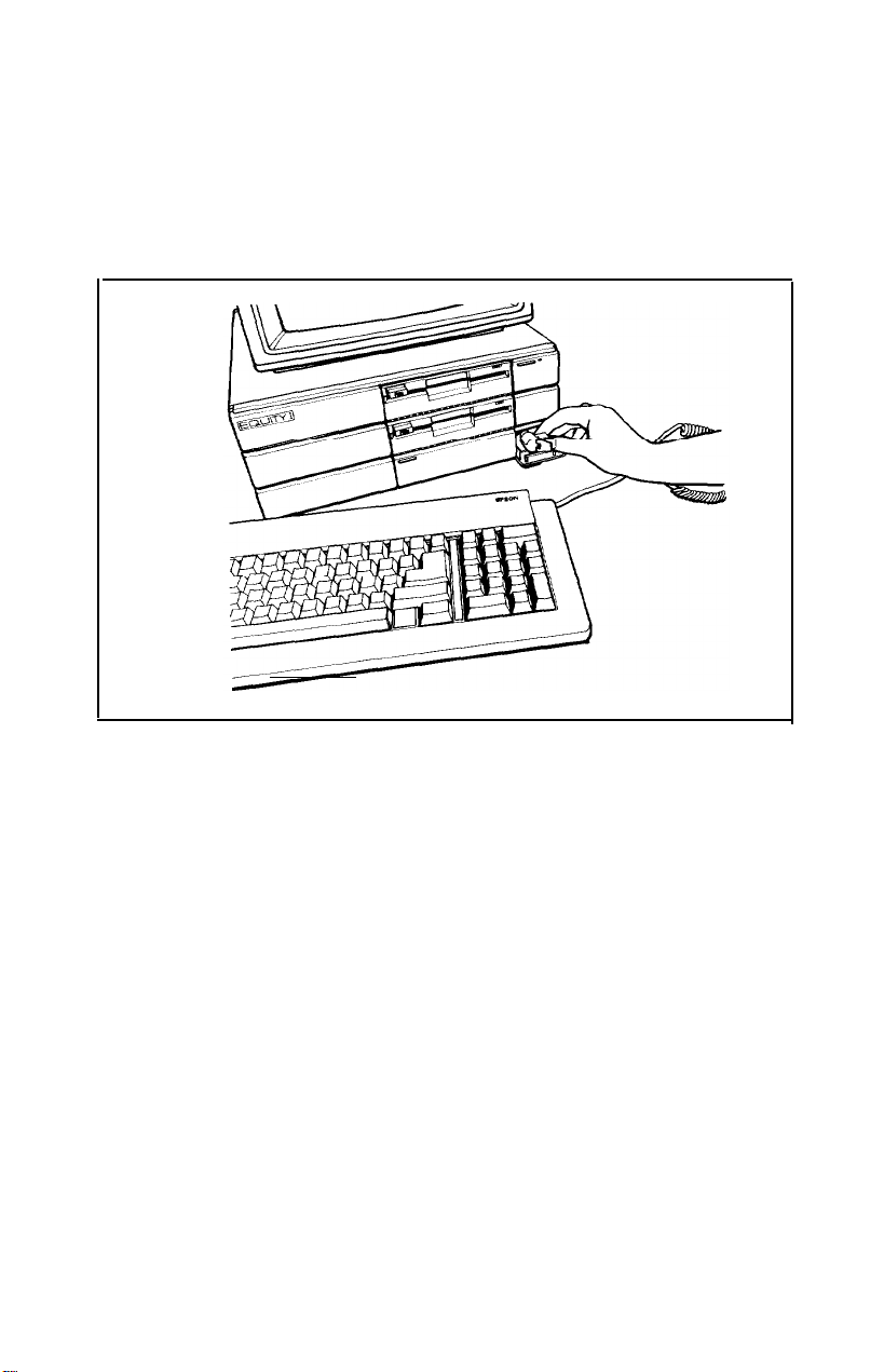
Inserting and Removing Disks
To insert a floppy disk into a disk drive, hold the disk with the label
face up and the write-protect notch to the left (so that the read/write slot
is away from you). Then slide it into the disk drive as shown in Figure
3-1. Be careful not to force the disk into the slot. When the disk is all the
way in, push in the button marked PUSH.
Figure 3-1. lnserting disks
To remove the disk, press the button again. As you release the button, the labelled edge of the disk pops out. Carefully pull out the disk,
place it in its protective envelope and store it properly.
Note: You need to format your blank floppy disks before you can use
them with your operating system. Refer to your MS-DOS or
other operating system manual for instructions on how to format
your blank disks.
23
Page 30

Resetting the Computer
You may occasionally need to reset the computer, either to load a
different operating system, or because a program has failed and the computer does not respond to your keyboard commands. However, reset-
ting the computer causes all data in memory to be lost, so if you have a
problem, you should reset the computer only as a last resort.
There are three ways to reset, and you should use them in this order:
If you are using MS-DOS, press Ctrl and Alt together with the Del
1.
key in the numeric keypad at the right of the keyboard. The display
screen goes blank for a moment, and any system disk in drive A
reloads. If the problem is not corrected after trying this, try the second method.
Press the reset button under the hinged flap beneath the disk drives.
2.
This has the same effect as the first method, but works even when the
keyboard is not responding. If this fails to have any effect, try the
third method.
Remove any disks from the floppy disk drives. Switch the Equity off
3.
with the power switch under the hinged flap at the top right of the
front panel. Wait for 5 seconds, then switch it back on.
WARNING: Some applications programs perform certain procedures
whenever you exit the program properly. If you reset the
computer in the middle of the program, these operations
cannot be performed, and you may lose data. This means
that you should not exit a program by resetting the computer unless you have to.
24
Page 31

Chapter 4
Using Disks
The disk drives in your computer let you store your work and pro-
grams on removable floppy disks for future use. All Equity systems have
at least one floppy disk drive; others may also have a hard disk drive,
either built-in or as an external unit.
The disk you insert in the floppy disk drive is a round piece of flexible
plastic covered with a magnetic coating. It is enclosed in a square pro-
tective jacket with holes to allow the disk drive to read and write to it.
The computer stores your information as a coded pattern in the magnetic
coating of the disk in the same way music is stored on magnetic tapes.
A hard disk drive works the same as a floppy disk drive, but the hard
disk has a larger storage capacity and is usually locked in a permanent
position. On a hard disk, the magnetic coating covers a polished metal
disk. Even hard disks are vulnerable, so you should always make backup
copies of important information on floppy disks.
The following sections give you some background information on
how disks work and tell you how to:
l Choose floppy disks
l
Care for your disks and disk drives
l
Protect your data
l
Use a single floppy disk drive
l
Use a hard disk drive.
How Disks Work
Disk drives function like a combination of a record player and a tape
recorder. They store your information on the disk as patterns of magne-
tized areas which are arranged into a set of circular tracks on each side of
the disk. A small read/write head in the disk drive interprets these mag-
netic patterns. When you insert a disk in the drive, the read/write head is
right over the large oval slot in the disk sleeve. When you access or write
to data on a disk, it spins at high speed so the read/write head can look at
different parts of the disk and move quickly between the edge and center.
25
Page 32

Because the data is stored magnetically, you can read it, write to it,
and erase it many times like a magnetic tape. The tracks on a disk are
arranged so any item of data can be reached very quickly. Although the
processes involved in controlling the disk drives are complex, you do not
need to worry about them because the disk operating system looks after
all the details.
Choosing Floppy Disks for the Equity
The Equity uses floppy disk drives that are double-sided, doubledensity, soft-sectored, 48 TPI (Tracks Per Inch) certified track units.
These disks are compatible with those used for the IBM PC. You can use
disks prepared and used with one computer on the other.
For best results, use only high-quality disks with reinforced hub
rings-the added reliability is well worth the extra cost. Be sure to select
disks that are double-sided, double-density and soft-sectored. Each disk
can hold 360K of data, the equivalent of about 150 pages of text.
Taking Care of your Disks and Disk Drives
Both floppy and hard disks are vulnerable to damage, and you need
to care for them properly. Follow these basic precautions when you use
floppy disks:
Never touch the magnetic surface. The oils on your fingertips can
damage the surface of the disk.
Handle disks carefully. Always hold disks by their protective jackets.
Keep them in their protective envelopes when they are not in use,
and return them to their storage box making sure they are not bending or sagging.
Do not place anything on top of your disks. They bend easily and do
not rotate properly in their sleeves if they are damaged.
Keep disks away from dust and dirt. Small particles of dust or dirt
scratch the magnetic surface (destroying data) and can also ruin the
read/write head in the disk drive.
26
Page 33

Be careful when you place labels on your disks. Attach labels firmly
but gently, and only along the top of the disk (next to the manufac-
tuer’s label). Avoid placing several labels on top of one other. They
may prevent the disk from spinning freely in the disk drive. It is best
to write on the label before placing it on the disk. Use only soft-tip
pens, not ballpoint pens or pencils, to write on a label that is already
attached to a disk.
Keep disks away from magnetic fields. Remember that disks store
their information magnetically, just like cassette tapes. There are
many sources of magnetism in and around your home or office, such
as electrical appliances and telephones, and particularly loudspeakers. Keep disks away from these items.
Keep disks in a moderate environment. Disks work best in normal
room-temperature and humidity conditions. Never leave them sit-
ting in the sun, or in extreme cold or heat. The temperature changes
inside a car in the middle of summer or the dead of winter can cause
severe damage.
If you have a hard disk drive, you should also take the following
precautions:
Never attempt to open the hard disk unit. The disk itself is enclosed
l
in an air-tight container to protect it from dust.
Never turn off the power to the computer or hard disk unit when the
l
SELECT lamp is ON. This LED indicates that the hard disk is in the
middle of reading from or writing to the disk. Turning the hard disk
off in the middle of a write operation can make all the information on
the disk unusable.
If you plan to move the hard disk unit, the read/write head must be
l
moved away from the disk recording area. Each operating system
has its own program to do this. The MS-DOS program to protect the
read/write head is called HDSIT Refer to the MS-DOS manual for
details.
Protecting your Data
There are two ways to make sure you do not lose the valuable information stored on your disks; write-protect your floppy disks and make
backup copies. Both of these methods are described below.
27
Page 34

Write-protecting floppy disks
The right edge of a floppy disk has a small, rectangular notch as
shown in Figure 4-1. If this notch is not covered, you can write new data
to the disk. If it is covered with an adhesive write-protect tab, you can
read data on the disk but you can not write new information to it or
delete any files. If you try to change the information on a write-protected
disk, an error message usually displays a warning that the disk is writeprotected. Write-protect tabs are usually included with new disks.
Figure 4-1. Write-protect notch
Making backup copies
It is a good idea to keep a second backup copy of all your important
data and program disks. With program disks, or the system master disks
supplied with your Equity, you should make backup copies to use, and
keep the originals in a safe place-away from your working disks. With
data disks, you should make up-to-date backups regularly (preferably
daily), and keep them apart from the originals.
Your MS-DOS manual describes how to make a backup of your
MS-DOS system disk. To make regular backups of other MS-DOS disks,
use the DU (Disk Utility) program or the DISKCOPY command. “Using
a Hard Disk Drive,” below, gives more information on backing up hard
disks.
28
Page 35

Using a Single Floppy Disk Drive
Some versions of the Equity have only one floppy disk drive. There
is a DIP switch (switch SW1-8) under the flap beneath the disk drives
which tells the computer how many floppy disk drives you have. This
switch should be DOWN (OFF) if you have two drives or UP (ON) if you
have just one drive. If you have only one floppy disk drive, make sure
this switch is UP correctly so the operating system can help you perform
those operations that normally require two drives.
Operating systems usually expect the computer to have at least two
physical disk drives. MS-DOS recognizes drives A and B for two floppy
disk drives, or A and C for a floppy and a hard disk drive. Some operations, such as copying files from one disk to another, require two drives.
With MS-DOS, if you have only one physical disk drive, the operating
system lets you treat it logically as two drives.
For example, if you give a command to copy from drive A to drive
B, MS-DOS copies from the first disk you place in the drive (A) to the
computer’s memory. Then it prompts you to insert the disk for drive B. It
copies from memory to the B disk you place in the drive. When the copy
is complete, the screen prompts you to reinsert the disk for drive A.
You may be swapping disks this way quite often, and it is easy to
forget which disk is which. To avoid accidentally losing your data, here
is a tip for keeping the disks straight: always hold the disk for the A drive
in your left hand and the disk for the B drive in your right. Another way
to avoid writing on the wrong disk is to place a write-protect tab on your
source disk. This allows you to read information, but not write over it.
For more information on using a single floppy disk drive with
MS-DOS, see your MS-DOS manual.
Using a Hard Disk Drive
The internal hard disk which comes with certain configurations of
the Epson Equity has a capacity of 20 megabytes-about 20 million characters. This is equivalent to around 60 floppy disks. Using the hard disk
greatly reduces the number of floppy disks you need and eliminates
much of the disk-swapping you have to do. You can do almost all your
work on the hard disk and copy your files to floppy disks as needed (to
make backups, for example).
29
Page 36

Although it has a lot of storage space, you should keep only the files
you use regularly on the hard disk, to make sure you always have plenty
of space available. Store your other files on floppy disks (you can use the
ARCHIVE utility in MS-DOS to back up your hard disk files). It is very
important to back up all your hard disk files on floppy disks. The hard
disk is very reliable, but you should always have backup copies in case
you lose any of your data from the hard disk.
You need to prepare your hard disk before you can use it. If you are
using a hard disk other than Epson’s, follow the preparation instructions
provided with your hard disk.
Before you can use the Epson internal hard disk, you must do four
things to prepare it:
Format the entire hard disk with the MS-DOS program
l
HDFMTALL.
Partition it to run the MS-DOS operating system with the MS-DOS
l
program HDPART.
Format the MS-DOS partition with the MS-DOS program
l
HDFORMAT and include the /S option to copy the MS-DOS operating system to the system tracks on the hard disk.
Copy the MS-DOS system utilities to the hard disk using XTREE or
l
the Copy command.
All of these programs are on your MS-DOS system disks and instructions for using them are in your MS-DOS manual.
Note: If you plan to use an operating system other than MS-DOS, you
need to use that operating system to partition the hard disk and
copy the system files to it.
30
Page 37

Chapter 5
Using Option Cards
Option cards are accessories that can be added to the computer to
provide extra capabilities. Examples of option cards you may want to
purchase are:
l Memory expansion card
.
Auto-dial modem
l Mouse card.
Up to three option cards can be installed in the Equity at one time,
but one position is always occupied by the color or monochrome video
card that operates your monitor.
Option cards are available from Epson and several other vendors. In
addition, multifunction boards (available from other vendors) allow you
to add other features without using additional slots.
Installing an Option Card
Some option cards, such as your video monitor card, come with
outlets for connecting external devices, while others are designed to
work directly within the Equity or to be used with built-in devices. If you
use an option card that has a connector for other equipment, (your video
monitor, for example) you need to remove the access slot cover on the
back panel of the computer that corresponds to the option card slot.
Otherwise, the installation procedure is the same for both types.
Removing the cover
WARNING: Never open the case of the Equity while it is plugged into
an electrical outlet. Turn off the power switch to the main
unit and any other peripheral devices connected to it, let
the machine stand for a few minutes, then unplug the
power cable before removing the case.
1.
If the monitor is on top of the computer, move it to one side. Turn the
main unit around so that the back panel faces you.
31
Page 38

The back panel is secured with three screws as shown in Figure
2.
Remove the screws with a Phillips screwdriver, and put them to one
Screws
5-l.
Figure 5-1. Back panel screws
The top cover is secured by two screws on each side of the computer
3.
as shown in Figure 5-2. With the back of the unit facing you, the two
screws on the left side of the unit are covered by small plastic inserts.
Gently remove the inserts with a small screwdriver, then remove the
screws on both sides of the computer. Put all the screws safely to one
side.
Figure
5-2.
Side screws under plastic inserts
32
Page 39

4. Figure 5-3 shows how to tilt the cover up slightly and move it away
from the main unit. Set the cover aside for now.
I
Figure 5-3. Removing cover
Inserting the option card
Most option cards can be placed into any of the three option slots.
Some cards may need to be installed in a specific slot. Check the option
card manual to find out if the option card has to be in a specific slot.
Even though option cards are designed to fit only one way, it is a
good idea to examine the card first and follow the instructions closely.
1.
Decide which option slot you want to use, then remove the retaining
screw and washer from the metal cover plate at the back of the slot.
Lift out the metal cover and put it in a safe place in case you later
remove the option card. Keep the screw and washer to secure the
option card to the computer.
2. Unpack the option card and adjust any switches or jumper connections that are necessary. When you handle the card, be careful not to
touch any of the contacts on the circuit board, especially along the
gold edge connections. If you need to put it down before installing it,
place it with the component side facing down on top of the original
packing.
Note: Pay specific attention to the warnings in your option board
instructions. Some devices have delicate CMOS chips that
should not be touched.
33
Page 40

3.
Grip the card firmly by the top corners and position it as shown. The
contact pins should be pointing down and the components should be
facing toward the inside of the main unit.
4. Slide the card into the slot as shown in Figure 5-4, placing the tab at
the bottom of the retaining bracket into the corresponding notch at
the back of the computer.
Figure 5-4. Option card installation
Once the connector pins are sitting in the connector slot, push firmly
5.
(but carefully) to fully insert the card. If the connector does not seem
to be going in smoothly, do not force it; pull it all the way out and try
again, being sure to keep it straight.
Secure the retaining bracket to the frame of the computer with the
6.
small screw and washer. Long option cards are held in position at the
free end by the piece of foam inside the top of the lid of the main unit.
When you have finished installing the card, keep the packing in case
7.
you need to remove the card.
34
Page 41

Removing an access slot cover
If the option card has an external device connection, such as your
video monitor, remove the access slot cover that corresponds to the posi-
tion of the option card.
1.
Hold the back panel of the computer with the inside facing you. The
individual access slot covers are held in position by a tab at the bottom and a clip at the top.
2. Remove the appropriate cover by pushing down on the clip and
pushing out. See Figure 5-5.
Figure 5-5. Removing access slot cover
Replacing the cover
With the option card properly installed, the last step is to replace the
cover of the main unit:
1.
With the back of the main unit facing you, hold the cover over the
computer with the side feet to the left of the main unit and the front
edge pointing slightly downward.
2.
Lower the cover onto the bottom half of the case making sure that
the bottom edges fit inside the case. At the same time, slide the front
35
Page 42

edge beneath the top edge of the front panel. Finally, lower the back
of the cover so that it is in position.
Secure the cover by replacing the two screws on both sides of the
3.
main unit. Replace the plastic inserts in the side feet by snapping
them into place.
Replace the back panel and the three screws along the top edge.
4.
Return the computer to its original position and reconnect it to the
5.
monitor, the keyboard, and any other peripherals you have.
Check to make sure the power switch is OFF. Reconnect the power
6.
cable to the back of the main unit and to an electrical outlet. Change
the DIP switches if necessary.
Perform any additional procedures in the option card manual. For
example, if the option card needs a program to control it, you may need
to add a command to the programs which start the operating system.
Removing option cards
To remove an option card, first detach any cable connected to the
card and remove the main unit cover; then follow the option card inser-
tion instructions in reverse.
Follow the same safety instructions and make sure you slide the card
straight up and out of the connector to avoid damaging it. Rewrap the
card (preferably with the original packing materials) and place it inside
the box for safe storage. Replace the metal access plate before replacing
the cover of the computer. When you have reassembled the unit, snap in
the plastic access slot cover. Remember to reset any DIP switches if necessary.
Some option cards which support devices like hard disk drives need
special commands to be included in the configuration of the operating
system. If you remove one of these cards, you need to reconfigure the
system.
Installing Memory Expansion Cards
If you have an Equity with 256K of memory, you can add extra
memory in two ways. A number of option cards are available to expand
the memory up to 640K, and a special Epson memory expansion card is
available from your Epson dealer to expand memory to 512K without
using an option slot.
36
Page 43

You install a memory option card the same way you install other
option cards. Installing an option card is described at the beginning of
this chapter. The procedure to install the Epson 256K expansion card is as
follows:
1. Remove the main unit cover as described earlier in this chapter.
2. The memory expansion connector is located at the front of the main
unit, to the left of the disk drives, as shown in Figure 5-6.
1
Memory expansion
connector
Figure 5-6. Memory expansion connector
Unpack the memory card. Hold it by the top corners with the com-
3.
ponent side to the right (facing the disk drive units).
Lower the card into position and push it firmly into the socket on the
4.
main circuit board. Be careful to align the connector correctly, and
do not force it into place. The card is held in position by the piece of
foam inside the cover of the main unit.
Replace the cover of the computer as previously described and
5.
reconnect the system.
37
Page 44

6. Adjust the DIP switches under the panel beneath the disk drives to
tell the computer how much memory is available.
7.
Turn ON the computer. You should see a message confirming the
amount of memory in the machine. If this is not correct, check the
DIP switch settings and reset the computer. If it is still incorrect,
check that the board is installed properly.
Using a mouse
The mouse is an accessory which is used with special software to
allow you to manipulate data on the screen. By moving the mouse over
your desktop, you direct a pointer on the screen. This enables you to
control an application program much easier than with a keyboard. By
pointing to an instruction on the screen and pressing one of the buttons
on the mouse, you carry out a command instantly, without having to
remember and type a complicated sequence of keys. Refer to the software manual or the program you are using with the mouse for exact
details on how to use it.
You may need to install an option card to use the mouse. Follow the
instructions at the beginning of this chapter to install the option card if
necessary. Connect the mouse’s tail to the connector at the end of the
card. If your mouse does not require a card, connect the tail to the serial
port.
When you want to use the mouse, remove the velcro strip that covers the roller; replace it when the mouse is not in use to keep out dust and
dirt. Use the mouse only on a hard, flat surface, never on carpet-like
material or on a wet surface.
During periods of frequent use, clean the roller on the mouse about
every two weeks. To clean the roller on an Epson mouse, turn it over and
remove the roller cover by pushing it to the side and lifting it out. For
another mouse, turn it over and remove the roller cover by turning it
counterclockwise. Remove the roller and wipe it with a clean, dry cloth,
then replace the roller and cover. There are no other user-serviceable
parts inside the mouse.
38
Page 45

Appendix A
Troubleshooting
You should not encounter any serious difficulties with the Equity, but
if anything out of the ordinary happens, this section should help. Usu-
ally, such a situation requires nothing more than repeating a software
procedure, correcting an operating system error (see the operating system manuals), or resetting the computer.
Most of the minor difficulties you might encounter can be resolved
by one of the suggestions below. If none of these solve the problem,
consult an Epson dealer about servicing the computer.
WARNING: If the computer has to be turned OFF for any reason,
always wait at least 5 seconds before switching it back ON.
Turning it OFF and ON rapidly can damage the computer.
The Computer Fails to Start Up
If the computer does not start up when the power switch is moved to
the ON position, follow these steps until you find a solution:
1. Check to see if the power indicator on the main unit is lit. If it is not,
remove any disks and turn the power OFF Wait 5 seconds and turn
the power back ON.
2.
If the lamp still does not come on, turn the power switch OFF. Then
check to see that the power cable is securely connected to the electrical outlet. Try turning the power switch ON again.
3. If this fails, check the electrical outlet. Plug a portable lamp into the
outlet you are using for the computer, and turn it on to see if there is
power.
The Video Display Does Not Appear
If the computer starts up but the display screen image does not
appear, follow these steps until you find a solution:
1. Increase the settings of the brightness and contrast controls on the
monitor.
2.
Check DIP switches
sure they are set correctly for your monitor.
l-6
and
l-7
on the front of the main unit to make
A-l
Page 46

Check to see that the power indicator on the monitor is lit. If it is not,
3.
turn the power OFF, wait 5 seconds, then turn the power back ON.
Wait to see if the display screen appears.
Remove any disks, then turn the monitor and main unit power
4.
switches OFF. Check that the monitor power cable is securely connected to the electrical outlet, and that the monitor cable is properly
connected to both the monitor and the main unit. Turn both power
switches ON again.
With the computer turned OFF check the electrical outlet for power.
5.
Plug a portable lamp into the outlet you are using for the monitor
and turn it on to see if it supplies power.
The Computer Hangs Up or Freezes
If the computer appears to be locked up and does not respond to the
keyboard, try the following:
1. Wait a few seconds. Some operations take longer to perform than
others. For example, a speadsheet program takes longer to recalculate an entire spreadsheet than to simply enter a figure. Also, some
BASIC programs that have a lot of calculations to perform can take
several minutes, or even hours. Be aware of the task the computer is
performing and judge the time period accordingly.
2. If the computer remains locked up, follow the reset sequences
described in Chapter
5.
Floppy Disk Problems
There are many kinds of disk problems that could occur, and just as
many reasons for them happening. If you are having trouble with your
disks, check the following questions:
1.
Is your disk damaged? If you are getting bad results of any type, the
disk could be damaged. Just to be sure, try your backup disk to see if
the same problem occurs. If the backup works, the first disk was
probably damaged. Make another copy from your backup.
2. Do you have the right type of disk? You should be using a doublesided, double-density, 48 TPI, soft-sectored disk. The disk type is
normally shown on the manufacturer’s label.
A-2
Page 47

3.
Is the disk write-protected? A write-protect tab may be placed over
the notch on the side of the disk. Think twice before removing it. It
might be a new disk, but it might also be a disk with information you
do not want to change or lose. Check the disk directory to determine
what files it contains. The operating system manual gives the proper
directory command. Although you should normally write-protect
program disks, there are some programs which use the program disk
for temporary files, and these do not work if the disk has been writeprotected.
Software Problems
There are various kinds of software problems, more so than there are
disk problems. If you are having trouble with a piece of software, here
are some of the basic problems, and the troubleshooting procedures that
you can use to help track them down:
1. The software program does not start. First check that you are follow-
ing the right procedure for the operating system you are using. Make
sure that a system disk has been placed in drive A.
2. An application routine is not working. Refer to the software manual
and complete the routine according to the instructions in the manual.
If this does not work:
l Start from the beginning by following the reset procedure
described in Chapter 5. Restart the program and try the routine
again after the computer has been reset.
l Some software may need the DIP switches to be set a particular
way to work properly. Make sure that the DIP switches are set
correctly for the type of monitor, the amount of memory, and the
number of disk drives you have. The DIP switch settings are listed
in Chapter 2. Always turn OFF the computer before changing the
DIP switches. The new settings are not read by the computer until
you turn it back ON.
Printer Problems
Most of the problems encountered while using a printer can be
solved by checking the manual that came with the printer. If the printer is
not working correctly and has just been installed, first make sure the
printer has power and is correctly connected to the computer. The
printer manual provides instructions on cable connections.
A-3
Page 48

If you have a serial printer, or if you have problems with paper feeding, you may also need to check the printer manual for the correct DIP
switch settings. The DIP switches on a printer help it communicate properly with the computer.
Option Card Problems
If you have installed an option card and get unexpected results,
double-check the following points:
1.
Is the option card installed correctly?
2.
Did you follow the set up and operating instructions described in the
option card manual?
Hard Disk Problems
Hard-disk units are extremely reliable, and most problems occur due
to accidentally repartitioning or reformatting part or all of the hard disk.
However, if the hard disk does not function properly, have it checked
immediately by an authorized Epson service center. The recording disk is
enclosed in an air-tight container that you should never open.
A-4
Page 49

CPU and Memory
%-bit
CPU
Main memory
ROM
8088 microprocessor, 4.77 MHz clockrate
256k or 512k; expandable to 640k
16k
Controllers
Video/Graphic
IBM compatible monochrome and color/graphics controller
Appendix B
Specifications
Disk
DMA
Interrupt
Control/Timer
Printer I/O
Serial I/O
Interfaces
Serial
Printer
Option slots
Speaker
Double-density floppy disk controller
Programmable DMA controller with 4 chan-
nels-two main systems (one for refreshing and
one for floppy disk controller), two available for
user peripherals
Programmable interrupt controllers, 8 interrupt
levels
One programmable interrupt timer
Programmable parallel interface
Multi-protocol serial controller
RS-232C, programmable, asynchronous, DB-25
male connector
Standard 8-bit parallel, DB-25 female connector
Three (one used by video card)
Internal, controlled by counter/ timer
B-3
Page 50

Power Supply
Mass Storage
Switching type, fan-cooled, -5 VDC,
+5VDC, + 12
55
w
Single/Dual
double-density, multiple format 360K per disk
VDC,
-12
VDC,
51/4-in.
floppy disks, double-sided,
115
VAC,
Capacity
Optional 5% in. hard disk, 20 MegaBytes
Keyboard
Detachable, two positions, 83 sculpted keys
Layout
56-key QWERTY main keyboard, 17-key
numeric pad, 10 function keys x 3 levels (normal/shift/alternate), user definable
Environmental Requirements
Temperature
Humidity
Operating range: 25” to 90°F (-4” to 35°C)
Storage range: 0” to 149°F (-20” to 65°C)
Operating range: 20 % to 80
non-condensing
Storage range: 10% to 90%,
non-condensing
Physical Characteristics (CPU only)
Width, in. (mm) 14.3 (360)
o/o,
Depth, in. (mm) 15.1 (380)
Height, in. (mm) 5.6 (142)
Weight, lb. (kg) 24 (52.8)
Power Requirements
104 VAC - 132 VAC, 50 to 60 Hz, MAX 144 VA
B-2
Page 51

Appendix C
Glossary
ASCII
American Standard Code for Information Interchange. A standard
way of assigning numerical codes to characters and control codes. The
character set on the Equity is based on the US ASCII code system, with
the addition of a large number of international and graphics characters.
Backup copy
A copy of a disk or file kept in case your working copy is damaged.
Baud rate
The number of signal/data bits that can be transmitted per second
during serial communications: it should be the same for the two communicating devices.
Bit
All computer information-whether words, figures or program
instructions-is stored as sets of numbers. Each individual number is
recorded in binary form, as either one or zero. A bit, short for binary
digit, is one of these numbers.
Booting
The process of loading the computer’s operating system.
Byte
A group of eight bits, which operate as a unit. A byte usually corres-
ponds to one character of text, but may also be part of a computer word
(a larger number). The size of the computer’s memory, and the capacity
of a disk, are normally expressed in kilobytes. One kilobyte contains
1024
Character
Chip
individual components.
way of working and the other equipment you are using.
bytes.
Any letter, number or symbol on the keyboard.
An integrated circuit, combining the functions of a large number of
Configuring
Preparing a piece of equipment or a program so that it suits your
C-l
Page 52

CPU
The unit inside a microcomputer that processes data and performs
calculations.
Device
A piece of equipment forming part of a computer system such as disk
drives, monitor, printer and so on.
DIP switch
One switch on a set of small switches (on the front panel of the computer) which give the system information about itself. DIP stands for
Dual In-line Package.
Disk
A device that stores information for future use. A disk may be a
floppy disk made of a flexible plastic magnetic coating, or a hard disk,
made of metal coated with a magnetic material. Unlike floppy disks,
hard disks cannot normally be taken out of their disk drives.
Disk drive
A unit in which a disk is held, so that the computer can read from it
and write to it.
File
A collection of data stored on a disk.
Formatting
Preparing a new disk to receive data similar to ruling lines on a blank
piece of paper before writing on it.
Hard copy
A printed copy of text or messages, or program, as opposed to a
display on a video monitor.
Hardware
The mechanical units that make up your computer system.
Interface
The software or hardware connecting two devices, computers, or
programs.
Mouse
A device which you roll over your desktop to control a pointer on
the screen and operate a program.
C-2
Page 53

Operating system
A set of software routines which control the way programs run on a
computer, and supervise all input and output to and from the system.
Parallel
A method of organizing communications between two pieces of
computer equipment in which the signals that make up each character
are sent simultaneously.
Partitioning
Dividing a hard-disk drive into sections for use by different operating systems.
Port
A connector for one of the computer’s interfaces.
Program
The complete sequence of computer instructions necessary to do cer-
tain functions.
RAM (Random Access Memory)
A memory device, usually a set of chips, structured so that any item
of data can be accessed quickly. RAM is usually volatile- that is, data
stored in RAM is lost when the power is turned off. The programs you
use and write, and the data they create, are temporarily stored in RAM
while you work.
Resetting
Reloading the computer’s operating system, so you can restart work
after a serious error, or begin using a different operating system. Resetting clears the computer’s memory, so you should reset only when it is
really necessary.
ROM (Read Only Memory)
A memory chip that can only be read and cannot be used for temporary storage. ROMs retain their contents even while the power to the
computer is off.
RS-232C
A widely-used standard for serial interfaces. Devices that are RS232C compatible can be connected to the Equity with very little
difficulty.
Serial
A method of communications between two pieces of computer
equipment in which the signals that make up each character are sent one
bit at a time.
C-3
Page 54

Software
The programs you run on your computer.
System disk
A disk containing the files which make up the operating system for
the computer.
C-4
Page 55

AC outlet 7
Alt 15, 24
Air circulation 4
Application programs 24
ARCHIVE utility 30
Arranging components 5
ASCII C-l
Auto-dial modems 31
Auxiliary outlet 7, 11
Back panel screws 32
Backup copies 23, 30, C-1
daily 23
making 27-28
Baud rate C-1
Backspace key 15
Bit C-1
Booting C-1
Brightness control, monitor A-1
Button, PUSH 23
Byte C-1
INDEX
Cable 36
connections 11-18, 31, 35
keyboard 13-14
parallel 15-16
serial 17
video monitor 11-12
Caps lock key 15
Centronics compatible connector 15
Character C-1
Chip C-1
CMOS 33
Color graphics
connectors 11
video card 1
Components, arranging 5
Computer See
Concurrent DOS 22
Configuring C-1
Contrast control, monitor A-1
Equity
Index-l
Page 56

Controllers
Control/Timer B-1
Disk B-1
DMA B-1
Interrupt B-1
Printer I/O B-1
Serial I/O B-1
Video/Graphic B-1
Cooling fan, main unit 22
Copying files 29
Cover, main unit 31-33, 35-36
CP/M-86 22
CPU B-1, C-2
Ctrl Alt Del 24
Ctrl key 15, 24
Cursor 15
Data 26-27, 30
DB-25 16
Del key 15, 24
Device C-2
DIP switch settings 12, 18-20
DIP switches 8, 36-37, C-2
built-in interfaces 18, 20
floppy disk drives 18-20, 29
functions 18-20
label 19
location of 18
memory size 18-19
memory table 19
monitor type 18-19, A-1, A-3
Disk 21, 25-30, C-2
attaching labels to 27
backing up 27
care and handling 26-27
comfortable environment for 27
compatibility with IBM-PC 26
floppy 25
floppy, blank 23
for Equity 26
how work 25
inserting and removing 23
magnetic surface of 26
problems A-2
system 21-24
type 26
using 25
write-protecting 28
Index-2
Page 57

Disk drive 25, C-2
hard See Hard disk drive
inserting floppy into 23
LED lamps 8
protector sheets 9, 21
single floppy 29
slot 8
DISKCOPY 28
Disk lock/release button 8
Display, monitor See Monitor
DOS 22
DU 28
Electromagnetic interference 4
Enter key 15
Environmental conditions 4
Environmental requirements
humidity B-2
temperature B-2
Epson printers 1
Equity
cable connections 11-18
components, arranging the 5
disk drive See
Disk drive
disk See Disk
electromagnetic interference 4
environmental conditions 4
front panel 7-8
main unit See
Main unit
main unit cover 31-33, 35-36
operating system 22-24, 29-30, C-3
packing materials 3
personal computer 1
powering up 21
power cord 6-7, 21, 31
power switch 8, 21-22, 24, A-1--A-2
rear panel 6-7
resetting the 24, C-3
self-diagnostic test, internal 22
special keys 14-15
unpacking 4
video monitor See Monitor
Exit 24
External devices See
Option cards
Index-3
Page 58

Floppy disk
drive 21, 26, 29
problems A-2
Format
floppy disk 23
hard disk 30
Formatting C-2
Front panel, Equity 7-8
GW-BASIC 15
Hard copy C-2
Hard disk drive 21-22, 25, 36
care of 27
internal 29-30
partition 30
problems A-4
Hardware C-2
HDFMTALL 30
HDFORMAT 30
HDPART 30
HDSIT 27
IBM-PC 1
character set 17
diskette format, compatibility 26
Initial system testing message 22
Input/output ports 6-7
Inserting and removing disks See Disk
Interfaces C-2
Option slots B-1
Parallel 1, 7, 15-16, 20
Printer B-l
Serial 1, 15, 17, 20, B-1
Speaker B-1
Internal self-diagnostic test 22
Keyboard
adjusting the legs 13-14
arranging the 5
cable 13-14
connecting 12-13
layout B-2
socket 8
Index-4
Page 59

Labels, disk 27
Magnetic fields 27
Magnetic surface of diskette 26
Main memory B-1
Main unit, Equity 1, 11, 22, 34-37
arrangement of 5
cover, removing the 31-33
cover, replacing the 35-36
power switch 22, 31
Mass storage capacity B-2
Memory expansion card 1, 31
connector for 37
installing 36-38
MODE 17
Modem 17
auto-dial 31
Moderate environment, for disks 27
Monitor 1, 21, 31, A-1
arranging 5
brightness and contrast A-1
cable A-2
color, RGB 1, 3
connecting the 11-12
display 12, 21, 24, A-1
Epson 3
external device connector 35
monochrome 1, 3
power switch A-2
video card 1, 3
video 3, 5
MS-DOS 1, 15, 17, 22-24, 27-30
Mouse 1, 38, C-2
mouse interface card 1, 31, 38
Multifunction cards 31
Num lock key 15
Operating system 22, 24, 29-30, C-3
loading an 23
Option cards 31-37
access slot cover 31, 35
connector pins 34
connector slot 34
external device connector 31, 35
Index-5
Page 60

installing 31-34
long 34
metal cover plate 33
panel, back 31-32, 35-36
problems A-4
retaining bracket 34
retaining screw 33-34
removing 26
slots 33
washer 33-34
Outlet 17, 31, A-1-A-2
AC 6-7
Auxiliary 7, 11
grounded 4
Packing materials 3
Parallel C-3
cable 16
interface 1, 7, 15-16, 20
printer port 6-7, 16
Partitioning C-3
Peripherals 2, 21, 31
devices 6
Physical chracteristics, Equity
depth B-2
height B-2
weight B-2
width B-2
Plastic inserts 32, 36
Port C-3
Power
LED lamp 8
requirements B-2
supply B-2
Power cord 6-7, 21, 31
Power switch 6, 8, 21-22, 24, A-1--A-2
Printer 16
cable 16-17
interface B-1
problems A-3
Program C-3
Protector sheets, disk drive 9, 21
PUSH button 23
Index-6
Page 61

RAM 22, C-3
Read-write head 25-27
Rear panel, Equity 6-7
Registration cards 3
Reset button 8, 24
Resetting the computer 8, 24, C-3
Retaining screws 17
ROM B-1, C-3
RS-232C serial port 7, 15, C-3
Screws
back panel 32
retaining 33
top cover 32, 36
Self-diagnostic test, Equity internal 22
Serial C-3
cable 5-2
interface 1, 15, 17, 20, B-1
port, RS-232C 17
Software C-4
Software problems A-3
Special character set 17
Special keys, Equity 14-15
Squeeze locks 17
System
arrangement 5
disk C-4
testing message 22
Tab key 15
Troubleshooting A-1--A-4
Unpacking the Equity 3
Video monitor See Monitor
Write-protect
disks 27-28
notch 23
tab 28-29
tab, removing A-3
Writing on labels 27
Index-7
Page 62

EPSON AMERICA, INC.
LIMITED WARRANTY
What Is Covered: Epson America, Inc. warrants that the Epson product enclosed
with this Limited Warranty conforms to the manufacturer’s specifications and is free
from defects in workmanship and material for a period of one year from the date of
original purchase made in the United States.
What We Will Do
tive during this period, you must promptly notify your Epson Dealer or an authorized
Epson Service Center and bring the product securely packaged in its original container
or an equivalent, along with proof of the date of original purchase, to your Epson
Dealer or to an authorized Epson Service Center. Epson America, Inc. will, at its
option, repair or replace on an exchange basis the defective unit, without charge for
parts or labor. Postage, insurance or shipping costs incurred in presenting your Epson
product for warranty service are your responsibility.
What This Warranty Does Not Cover: This warranty covers only normal consumer use. Epson is not responsible for warranty service should the Epson label or
logo or the rating label or serial number be removed or should the product fail to be
properly maintained or fail to function properly as a result of misuse, abuse, improper
installation, neglect, improper shipping, damage caused by disasters such as fire,
flood, and lightning, or service other than by an authorized Epson Service Center.
THE WARRANTY AND REMEDY PROVIDED ABOVE ARE EXCLUSIVE AND
IN LIEU OF ALL OTHER EXPRESS WARRANTIES AND UNLESS STATED
HEREIN, ANY STATEMENTS OR REPRESENTATIONS MADE BY ANY OTHER
PERSON OR FIRM ARE VOID. THE DURATION OF ANY IMPLIED WARRANTIES OF MERCHANTABILITY OR FITNESS FOR A PARTICULAR PURPOSE ON
YOUR EPSON PRODUCT SHALL BE LIMITED TO THE DURATION OF THE EXPRESS WARRANTY SET FORTH ABOVE. EXCEPT AS PROVIDED IN THIS
WRITTEN WARRANTY, NEITHER EPSON AMERICA, INC. NOR ITS AFFILIATES SHALL BE LIABLE FOR ANY LOSS, INCONVENIENCE, OR DAMAGE,
INCLUDING DIRECT, SPECIAL, INCIDENTAL, OR CONSEQUENTIAL DAMAGES, RESULTING FROM THE USE OR INABILITY TO USE THE EPSON PRODUCT, WHETHER RESULTING FROM BREACH OF WARRANTY OR ANY
OTHER LEGAL THEORY.
Some states do not allow limitations on how long an implied warranty lasts and
some states do not allow the exclusion or limitation of incidental or consequential
damages, so the above limitation and exclusion may not apply to you.
This warranty gives you specific legal rights, and you may also have other rights
which vary from state to state.
How To Obtain Warranty Service Information: You
ranty service information by contacting your Epson Dealer or by contacting Epson
America, Inc. at the address or phone number printed below:
To Correct Problems: Should your Epson product prove defec-
may request additional war-
Epson America, Inc.
Service Division
23610 Telo Street
Torrance, CA 90505
(213)534-4234
0 0
0
 Loading...