

Page 1
®
6(59,&(0 $ 18$/
Laser Printer
EPSON EPL-N4000
SEPG98002
Page 2

Notice
All rights reserved. No p art of t his manual may be reprod uced, stored i n a ret rieval syste m, or trans mitted in any form or by a ny means el ectroni c,
mechanical, photocopying, or otherwise, without the prior written permission of SEIKO EPSON CORPORATION.
All effort have been made to ensure the acc uracy of the contents of this manual. However, should any errors be detected, SEIKO EPSON would
greatly appreciate being informed of them.
The contents of this manual are subject to change witho u t notice.
All effort have been made to ensure the acc u racy of the contents of this manual. However, should any errors be detected, SEIKO EPSON would
greatly appreciate being informed of them.
The above not withstanding SEIKO EPSON CORPORATION can assume no responsibility for any errors in this manual or the consequences
thereof.
EPSON is a registered trademark of SEIKO EPSON CORPORATION.
General Notice: Other product names used herein are for identification purpose only and may be trademarks or registered trademar ks of their
respective owners. EPSON disclaims any and all rights in those marks.
Copyright © 1998 SEIKO EPSON CORPORA TION. Printed in Japan.
Page 3

PRECAUTIONS
Precautionary notations throughout the text are categorized relative to 1)Personal injury and 2) damage to equipment.
DANGER
WARNING
The precautionary measures itemized below should always be observed when performing repair/maintenance procedures.
Signals a precaution which, if ignored, could result in serious or fatal personal injury. Great caution should be exercised in
performing procedures preceded by DANGER Headings.
Signals a precaution which, if ignored, could result in damage to equipment.
DANGER
1. ALWAYS DISCO NNECT THE PRODUCT FROM THE POWER SOURCE AND PERIPHERAL DEVICES PERFORMING ANY
MAINTENANCE OR REPAIR PROCEDURES.
2. NO WORK SHOULD BE PERFORMED ON THE UNIT BY PERSONS UNFAMILIAR WITH BASIC SAFETY MEASURES AS DICTATED
FOR ALL ELECTRONICS TECHNICIANS IN THEIR LINE OF WORK.
3. WHEN PERFORMING TESTING AS DICTATED WITHIN THIS MANUAL, DO NOT CONNECT THE UNIT TO A POWER SOURCE UNTIL
INSTRUCTED TO DO SO. WHEN THE POWER SUPPLY CABLE MUST BE CONNECTED, USE EXTREME CAUTION IN WORKING ON
POWER SUPPLY AND OTHER ELECTRONIC COMPONENTS.
WARNING
1. REPAIRS ON EPSON PRODUCT SHOULD BE PERFORMED ONLY BY AN EPSON CERTIFIED REPAIR TECHNICIAN.
2. MAKE CERTAIN THAT THE SOURCE VOLTAGES IS THE SAME AS THE RATED VOLTAGE, LISTED ON THE SERIAL NUMBER/
RATING PLATE. IF THE EPSON PRODUCT HAS A PRIMARY AC RATING DIFFERENT FROM AVAILABLE POWER SOURCE, DO NOT
CONNECT IT TO THE POWER SOURCE.
3. ALWAYS VERIFY THAT THE EPSON PRODUCT HAS BEEN DISCONNECTED FROM THE POWER SOURCE BEFORE REMOVING OR
REPLACING PRINTED CIRCUIT BOARDS AND/OR INDIVIDUAL CHIPS.
4. IN ORDER TO PROTECT SENSITIVE MICROPROCESSORS AND CIRCUITRY, USE STATIC DISCHARGE EQUIPMENT, SUCH AS
ANTI-STATIC WRIST STRAPS, WHEN ACCESSING INTERNAL COMPONENTS.
5. REPLACE MALFUNCTIONING COMPONENTS ONLY WITH THOSE COMPONENTS BY THE MANUFACTURE; INTRODUCTION OF
SECOND-SOURCE ICs OR OTHER NONAPPROVED COMPONENTS MAY DAMAGE THE PRODUCT AND VOID ANY APPLICABLE
EPSON WARRANTY.
Page 4

About This Manual
This manual describes basic functions, theory of electrical and mechanical operations, maintenance and repair procedures of EPL-N4000. The
instructions and procedur es included herein are intended for the experienced repair technicians, and at tention should be given to the precaut ions on
the preceding page.
Contents
This manual consists of six chapters and Appendix.
CHAPTER 1. PRODUCT DESCRIPTIONS
Provides a general overview and specifications of the
product.
CHAPTER 2. OPERATING PRINCIPLES
Describes the theory of electrical and mechanical
operations of the product.
CHAPTER 3. TROUBLESHOOTING
Provides the step-by-step procedures for the
troubleshooting.
CHAPTER 4. DISASSEMBLY AND ASSEMBLY
Describes the step-by-step procedures for
disassembling and assembling the product.
CHAPTER 5. ADJUSTMENTS
Provides Epson-approved methods for adjustment.
CHAPTER 6. MAINTENANCE
Provides preventive maintenance procedures and the
lists of Epson-approved lubricants and adhesives
required for servicing the product.
APPENDIX
Provides the following additional information for
reference:
• Connector pin assignments
• Electric circuit boards components layout
• Exploded diagram
• Electrical circuit boards schematics
Symbols Used in This Manual
Various symbols are used throughout this manual either to provide
additional information on a specif ic topic or to warn of possible danger
present during a procedure or an action. Be aware of all symbols when
they are used, and always read WARNING, CAUTION or NOTE
messages.
Indicates an operating or maintenance procedure, practice
or condition that, if not strict ly obser ved, could r esult in injur y
or loss of life.
CAUTION
CHECK
PO IN T
Indicates an operating or maintenance procedure, practice,
or condition that, if not strictly observed, could result in
damage to, or destruction of, equipment.
May indicate an operating or maintenance procedure,
practice or condition that is necessary to accompli sh a task
efficiently. It may also provide additional information that is
related to a specific subject, or comment on the results
achieved through a previous action.
Page 5

Safety Information
To prevent accidents during a maintenance procedure, strictly observe
the Warnings and Cautions. Do not do anything that is dang erous or not
within the scope of this document.
Do not do anything that is dangerous even if not specifically described
in this manual. In addition to the descriptions below and those given in
this manual, there are many situations and circumstances that are
dangerous. Be aware of these when you are working with the printer.
Safety Precautions
POWER SUPPLY AND ELECTRICAL COMPONENTS
Before starting any service procedure, turn off the printer and unplug
the power cord from the wall outlet. If you must service the printer with
the power applied, be aware of the potential for electrical shock and do
all tasks by following the procedures in this manual.
W ARNING
Do not touch any electrified component unless you ar e
instructed to do so by service procedure.
Page 6
MECHANICAL COMPONENTS
LASER ASSEMBLY
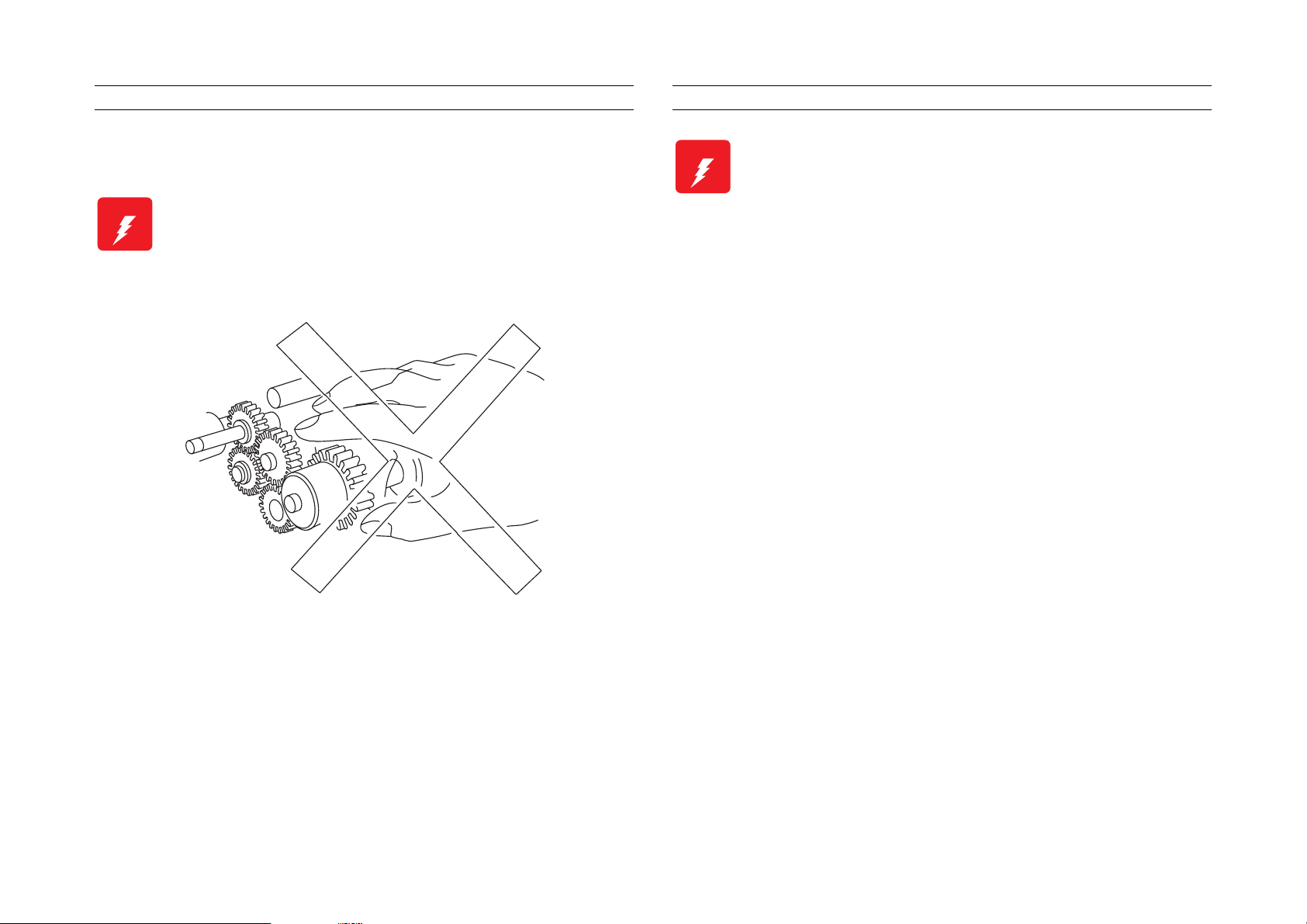
If you service a driving assembly (e.g., gears), first turn off the power
and unplug the power cord. Then manually rotate the assembly.
W ARNING
Do not try to manually rotate or stop the drive
assemblies while the Main Motor is running.
W ARNING
This printer uses a laser as part of the pri nting process.
The laser beam is a very powerful, straight, narrow
beam of light that produces extreme heat at its focal
point. The laser beam in this printer is invisible.
Although you cannot see the beam, it can still cause
severe damage. Direct eye exposure to the laser beam
may cause eye injury or blindness.
Never place a mirror or a reflective tool or object in the
laser beam path.
To avoid permanent eye damage, follow these directions;
Before starting any service procedure, swi tch off the printer
power and unplug the power cord from the wall outlet.
Do not disassemble the ROS Assembly or any laser component
that displays a Laser Warning Sticker.
Use caution when you are working around the ROS Assembly or
when you are performing laser related repair procedures.
Do not disassemble the printer in such a way that the laser
beam can exit the printer engine during a print cycle.
Page 7

Safety Components
Make sure fuses, interlock switches, covers and panels are all
functioning properly after you have reinstalled or replaced them.
Warning/Caution Labels
WARNING and CAUTION labels are stuck on dangerous parts in the
printer to make you aware of the potential dangers that are present
when you are working with those parts.
Page 8

Revision Status
Revision Issued Date Description
Rev. A November 4, 1998 First Release
Page 9

EPSON EPL-N4000
Table of Contents
Product Description
Features.................................................................................................. 2
Basic Specification................................................................................ 3
Controller Specification..................................................................... 3
Engine Specification ......................................................................... 4
Paper Specification ........................................................................... 5
Electrical Specification...................................................................... 7
Reliability, Durability and Maintainability........................................... 8
Safety Approval............................................................................... 10
Environmental Specification............................................................ 11
Operating Environment(including optional parts) .....................11
Storage Environment(in cludi ng option al parts ) ......................... 11
Altitude .................. ............. ............. ............. ............. ............. ...11
Vibration Tolerance .... ....... ...... ....... ...... ....... .............................11
External Dimension and weight ...................................................... 12
Other Specifications........................................................................ 13
Consumables.................................................................................. 13
Configuration................................................................................... 13
Host Interface Specification ............................................................ 14
Parallel Interface ... ...... ....... ...... ....... ...... ....... ...... ....... ................14
Ethernet Interface Specification ................................................ 15
Type-B Interface .......................................................................15
OPERATION ......................................................................................... 16
Control Panel .................................................................................. 16
Panel Setting Mode......................................................................... 19
One Touch Setting Mode .........................................................19
List of Setting Items ..................................... ...... ....... ...... ....... ... 1 9
Special Operation ........................................................................... 26
Maintenance Mode ......................................................................... 28
Operation .................... .............................................. ................28
Engine Status Sheet ....................................................................... 29
Initialization Process....................................................................... 33
Operating Principles
Mechanical Drive ................................................................................. 35
Overview......................................................................................... 35
Mechanical Drive Component......................................................... 35
Offset Motor ..............................................................................36
Main Motor and Main Drive Assembly ......................................36
Lift Up Motor 1 and Lift Up Motor 2 ..........................................37
Motor Control ............................................................................37
Paper Path. ...... ............................................. ....... ...... ....... .................... 38
Paper Path Components................................................................. 39
Paper Feed, Transport and Paper Eject Drive................................ 41
Mechanical drive for paper fed from the MSI.................................. 41
Mechanical Drive for Paper Fed from Tray1................................... 42
Mechanical Drive for Paper Fed from Tray2................................... 42
Mechanical Drive for Registration................................................... 43
Mechanical Drive for the Drum and BTR ........................................ 43
Mechanical Drive for the Fuser....................................................... 44
Mechanical Drive for Exit Drive....................................................... 44
Mechanical Drive for Offset............................................................. 45
Paper Path Component Control...................................................... 45
ROS (Raster Output Scanner).................... ........................................ 46
ROS Components................ ...... ....... ...... ....... ...... ....... ...... ....... ...... . 46
Housed inside the ROS Assembly ...........................................46
ROS Operation ....... ....... ...... ...... ....... ...... ........................................ 47
Image Resolution ............................ ....... ...... ....... ...... ....... ...... .. 48
ROS Control ....................... ....... ...... ....... ...... ....... ...... ....... ...... .. 48
Print Process ....................................................................................... 50
Charge............................................................................................ 51
Exposure......................................................................................... 52
Develop........................................................................................... 53
Transfer........................................................................................... 54
Detack............................................................................................. 54
Fusing............................................................................................. 55
Clean............................................................................................... 55
Print Sequence .................................................................................... 56
Operating Principles for Power Supply Circuit ................................ 58
Power Supply Circuit....................................................................... 58
Power Supply Components ............................................................ 58
Printer Control..................................................................................... 61
Printer Control Components ........................................................... 63
Rev.A 1
Page 10

EPSON EPL-N4000
Machine Control Unit PWB (MCU PWB) ..................................63
Components attached to or associated with the MCU PWB: ...63
Function of the MCU during printer control ...............................67
Controller ........................................................................................ 69
Functions of the Controller ............. ...... ....... .............................69
Specification on the Controller .................................................. 69
Troubleshooting
Troubleshooting.................................................................................. 72
Service Flowchart ........................... ....... ...... ....... ...... ....... ...... ....... .. 72
FIP Flowchart......... ...... ...... ....... ...... ....... ...... ....... ...... ....... ...... ......... 73
How to use the FIP Flowchart ..................................................73
How to follow a FIP ...................................................................74
General Notes on Using FIPs ...................................................74
Printer Message................................................................................... 76
Printer Message.............................................................................. 78
Service Req. Error .......................................................................... 81
Engine Error ............................................................................. 81
Controller Error .........................................................................81
Operation when Service Req. Error Occurs.................................... 82
Printer Performance Problems(not indicated by Error Codes)....... 83
Inoperative Printer........................................................................... 83
Erratic Operation.......... ...... .............................................. ...... ....... .. 85
Inoperative Control Panel ............................................................... 86
Inoperative Main Drive Assembly ................................................... 87
Inoperative Paper Feed Drive......................................................... 89
J1-2 is not displayed when the EP Cartridge is out of toner ........... 90
Inoperative Interlock Switch............................................................ 90
Inoperative Offset............................................................................ 91
Image Quality FIPs .............................................................................. 92
Light(Undertoned) Prints................................................................. 93
Blank White..................................................................................... 95
Black Prints.................. ...... ....... ...... ....... ...... ................................... 96
Vertical Band Deletions................................................................... 98
Horizontal Band Deletions .............................................................. 99
Vertical Streaks............................................ ....... ...... .................... 100
Horizontal Streaks......................................................................... 101
Spot Deletions............................................................................... 103
Spots............................................................................................. 104
Residual Image or Ghosting ......................................................... 106
Background................................................................................... 107
Skewed Image .............................................................................. 109
Damaged Prints ............................................................................ 110
Unfused Image or Image Easily Rubbed Off ................................ 111
Image not Registered Correctly.................................................... 111
Secondary FIPs ................................................................................. 112
Disassembly and Assembly
Overview ............................................................................................ 115
Cautions before starting................................................................ 115
Tools............................................................................................. 115
Notations in the Manual ................................................................ 115
Procedures for Disassembling ........................................................ 117
Fuser Full Cover ........................................................................... 120
Removal ................................................................................. 120
Installation .............................................................................. 120
Top Cover Assembly..................................................................... 121
Removal ................................................................................. 121
Installation .............................................................................. 121
Rear Cover Assembly................................................................... 122
Removal ................................................................................. 122
Installation .............................................................................. 122
Right Cover................................................................................... 123
Removal ................................................................................. 123
Installation .............................................................................. 123
Control Panel ................................................................................ 124
Removal ................................................................................. 124
Installation .............................................................................. 124
Rear Cover 1TM ........................................................................... 125
Removal ................................................................................. 125
Installation .............................................................................. 125
Tray 1 Lift Up Motor ...................................................................... 126
Removal ................................................................................. 126
Installation .............................................................................. 126
Tray 1 Feed Clutch ....................................................................... 127
Removal ................................................................................. 127
Installation .............................................................................. 127
Feed, Nudger, and Retard Rolls ................................................... 128
Rev.A 2
Page 11

EPSON EPL-N4000
Removal .................................................................................128
Installation .............................................................................. 128
Tray1 Take Away Roll Assembly .................................................. 129
Removal .................................................................................129
Installation .............................................................................. 130
Tray 1 Feeder Assembly............................................................... 132
Removal .................................................................................132
Installation .............................................................................. 133
Support Assembly Spring ............................................................. 134
Removal .................................................................................134
Installation .............................................................................. 134
Tray1 Retard Assembly ................................................................ 135
Removal .................................................................................135
Installation .............................................................................. 135
Tray 1&2 Front Chute Assemblies................................................ 137
Removal .................................................................................137
Installation .............................................................................. 137
Tray 1 & Tray 2 Level Sensors ..................................................... 138
Removal .................................................................................138
Installation .............................................................................. 138
Tray1 & Tray 2 No Paper Sensors................................................ 139
Removal .................................................................................139
Installation .............................................................................. 139
Tray 1 & Tray 2 Paper Size Sensors ............................................ 140
Removal .................................................................................140
Installation .............................................................................. 140
Tray 2 Feed Clutch ....................................................................... 141
Removal .................................................................................141
Installation .............................................................................. 141
Tray 2 Feeder Assembly............................................................... 142
Removal .................................................................................142
Installation .............................................................................. 143
Tray2 Take Away Roll Assembly .................................................. 144
Removal .................................................................................144
Installation .............................................................................. 144
Tray 2 Retard Assembly ............................................................... 145
Removal .................................................................................145
Installation .............................................................................. 145
MSI Feeder Assembly (Manual Feeder)....................................... 146
Removal .................................................................................146
Installation .............................................................................. 146
MSI Tray Assembly....................................................................... 146
Removal ................................................................................. 146
Installation .............................................................................. 147
MSI Support Assembly ................................................................. 148
Removal ................................................................................. 148
Installation .............................................................................. 148
MSI Size Sensor Assembly........................................................... 149
Removal ................................................................................. 149
Installation .............................................................................. 150
MSI Feed Clutch ........................................................................... 151
Removal ................................................................................. 151
Installation .............................................................................. 153
MSI Feed Roll ............................................................................... 154
Removal ................................................................................. 154
Installation .............................................................................. 154
MSI Nudger Roll............................................................................ 155
Removal ................................................................................. 155
Installation .............................................................................. 155
MSI Nudger Roll Assembly........................................................... 156
Removal ................................................................................. 156
Installation .............................................................................. 156
MSI Pad........................................................................................ 157
Removal ................................................................................. 157
Installation .............................................................................. 157
MSI Friction Clutch........................................................................ 158
Removal ................................................................................. 158
Installation .............................................................................. 158
MSI No-Paper Sensor Assembly.................................................. 159
Removal ................................................................................. 159
Installation .............................................................................. 159
L/H Low Cover Assembly........... ....... ...... ...................................... 160
Removal ................................................................................. 160
Installation .............................................................................. 161
Left Lower Cover Assembly.......................................................... 162
Removal ................................................................................. 162
Installation .............................................................................. 162
Left Lower Cover Pinch Roll Assembly......................................... 163
Removal ................................................................................. 163
Installation .............................................................................. 163
Rev.A 3
Page 12

EPSON EPL-N4000
Left Lower Cover Interlock Switch ................................................ 164
Removal .................................................................................164
Installation .............................................................................. 164
Tray 2 Take Away Sensor............................................................. 165
Removal .................................................................................165
Installation .............................................................................. 165
Registration Clutch........................................................................ 166
Removal .................................................................................166
Installation .............................................................................. 166
Left Upper Cover Assembly .......................................................... 167
Removal .................................................................................167
Installation .............................................................................. 168
Left Chute Assembly..................................................................... 169
Removal .................................................................................169
Installation .............................................................................. 169
Registration Chute Assembly........................................................ 170
Removal .................................................................................170
Installation .............................................................................. 170
Registration Roll Assembly ........................................................... 171
Removal .................................................................................171
Installation .............................................................................. 171
Registration Sensor ...................................................................... 172
Installation .............................................................................. 172
Installation .............................................................................. 172
ROS Assembly.............................................................................. 173
Removal .................................................................................173
Installation .............................................................................. 173
EP Cartridge (Toner Cartridge)..................................................... 174
Removal .................................................................................174
Installation .............................................................................. 174
BTR Assembly (Transfer roller unit).................... ...... ....... ...... ....... 176
Removal .................................................................................176
Installation .............................................................................. 176
Toner Sensor ................................................................................ 177
Removal .................................................................................177
Installation .............................................................................. 177
CRU Interlock Switch.................................................................... 178
Removal .................................................................................178
Installation .............................................................................. 178
Fuser Assembly ............................................................................ 179
Removal ................................................................................. 179
Installation .............................................................................. 179
Fuser Drive Assembly................................................................... 180
Removal ................................................................................. 180
Installation .............................................................................. 181
Offset/Exit Assembly..................................................................... 182
Removal ................................................................................. 182
Installation .............................................................................. 182
Exit Drive Assembly...................................................................... 183
Removal ................................................................................. 183
Installation .............................................................................. 183
Exit Gate Solenoid ........................................................................ 184
Removal ................................................................................. 184
Installation .............................................................................. 184
Offset Motor .................................................................................. 185
Removal ................................................................................. 185
Installation .............................................................................. 185
Face Up Exit Sensor..................................................................... 186
Removal ................................................................................. 186
Installation .............................................................................. 186
Offset Roller Assembly ................................................................. 187
Removal ................................................................................. 187
Installation .............................................................................. 187
Lower Chute Assembly................................................................. 188
Removal ................................................................................. 188
Installation .............................................................................. 188
Upper Chute Assembly................................................................. 189
Removal ................................................................................. 189
Installation .............................................................................. 189
Exit Roll Assembly ........................................................................ 190
Removal ................................................................................. 190
Installation .............................................................................. 190
Full Stack Sensor.......................................................................... 191
Removal ................................................................................. 191
Installation .............................................................................. 191
Inverter Clutches........................................................................... 192
Removal ................................................................................. 192
Installation .............................................................................. 192
Main Drive Assembly .................................................................... 193
Removal ................................................................................. 193
Rev.A 4
Page 13

EPSON EPL-N4000
Installation .............................................................................. 195
Main Power Switch ....................................................................... 196
Removal .................................................................................196
Installation .............................................................................. 196
Low Voltage Power Supply(LVPS) Assembly............................... 197
Removal .................................................................................197
Installation .............................................................................. 197
AC Driver PWB ............................................................................. 198
Removal .................................................................................198
Installation .............................................................................. 198
High Voltage Power Supply(HVPS) Assembly.............................. 199
Removal .................................................................................199
Installation .............................................................................. 199
Noise Filter PWB........................................................................... 200
Removal .................................................................................200
Installation .............................................................................. 200
Left Cover Interlock Switch Assembly........................................... 201
Removal .................................................................................201
Installation .............................................................................. 201
MCU(Machine Control Unit) PWB................................................. 202
Removal .................................................................................202
Installation .............................................................................. 203
Controller Board............................................................................ 204
Removal .................................................................................204
ESS Box.... ............................................. ...... ....... ...... .................... 205
Removal .................................................................................205
Installation .............................................................................. 205
Adjustment
Maintenance
Maintenance....................................................................................... 209
Exchange Units and Parts by User............................................... 209
Appendix
Connector Pin Diagram.................................................................... 211
Pin Alighnment.............................................................................. 211
How to use P/J location Table and Map ....................................... 213
Signal Information............................. ...... ....... ............................... 221
Board Component Layout ................................................................ 233
C262 Main Board Component ...................................................... 233
Parts List............................................................................................ 235
Top Cover Assembly..................................................................... 235
Front Cover................................................................................... 236
Rear, Left and Right Cover........................................................... 237
Tray Unit - Paper Stack................................................................. 238
Tray Unit - End Guide ................................................................... 239
Tray Interface -Tray 1 ................................................................... 240
Paper Pick Up - Tray 1.................................................................. 241
Retard and Take Away-Tray 1...................................................... 242
Tray Interface-Tray 2 .................................................................... 243
Paper Pick Up-Tray 2.................................................................... 244
Retard and Take Away- Tray 2..................................................... 245
Feed Drive Transmission.............................................................. 246
Multi Sheet Inserter and MSI/Duplex Support............................... 247
MSI Feeder Assembly................................................................... 248
Upper Feeder Assembly ............................................................... 249
MSI Tray Assembly....................................................................... 250
Tray 1 Frame and Left Cover........................................................ 251
Tray 2 Frame and Left Cover........................................................ 252
Registration................................................................................... 253
Left Upper Cover Assembly.......................................................... 254
Transport Chute Assembly ........................................................... 255
ROS Assembly........ ....... ............................................. ...... ....... ..... 256
Xerography and Development...................................................... 257
Fuser Assembly ............................................................................ 258
Exit Lower Chute........................................................................... 259
Offset Roller.................................................................................. 260
Exit Upper Chute Assembly.......................................................... 261
Exit Drive Assembly...................................................................... 262
Main Drive Assembly .................................................................... 263
Fuser Drive Assembly................................................................... 264
Power Inlet and LVPS................................................................... 265
HVPS and MCU PWB................................................................... 266
Controller Assembly...................................................................... 267
Rev.A 5
Page 14

PRODUCT DESCRIPTION
&+$37(5
Page 15
EPSON EPL-N4000 Chapter 1 Product Description
1.1 Features
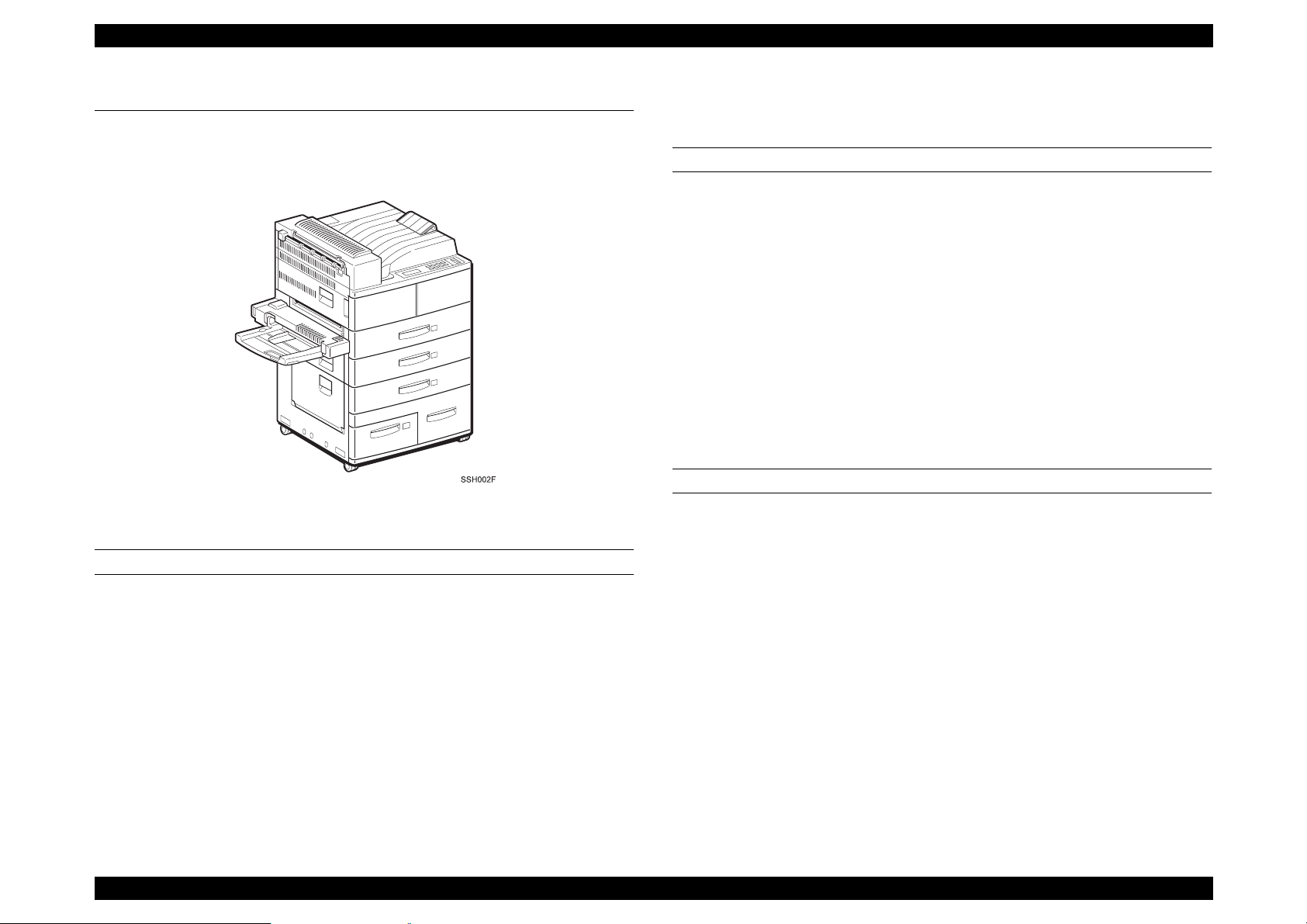
EPL-N4000 is non-impact page printer applied with laser xerographic
method.
Figure 1-1. Exterior View of EPL-N4000
ENGINE FEATURES
High speed & high reliability A3 engine.
Resolution:600 dpi
Wide range of options(dupl ex unit, face-up tray, ENV tray, mail box,
3-bin finisher, HDD)
CONTROLLER FEATURES
High speed controller, employing new CPU
CPU VR4700 133MHz
SDRAM DiMMs adopted
16MB RAM fitted as standard
Expansion to 256 MB
Two standard interface
IEEE 1284 parallel interfaces
Ethernet interface
1 slot for Type B interface
PGI (Photo Grade Improvement) fitted
SOFTWARE FEATURES
Emulation installed
PCL5e, XL(TBD) Paper handling support
PS level2 (EPSON script) Paper handling support
ESC/Page PGI support, paper handling support
FX, ESC/P2,1239X Paper handling support
ESC/PageC*
1
, ESC/PC*
1
PGI support, paper handling support
Printing speed:40 ppm(A4)
1
*
Standard paper supply includes two univ ersa l ca ssettes (500 sheet s
x2) and manual feed tray(50 sheets)
Requires C version DIMMs installed. C version DIMMs include C
version font.
2. Firmer can be rewritten via the parallel port.
Option support for high-capacity lower tray(500-sheets(A4 to B) +
Firmware can be rewritten via the network. (TBD)
1000 sheets(A4, Letter, and Executive sizes)
Shifter(jogger)fitted as standard
Rev.A 2
Page 16
EPSON EPL-N4000 Chapter 1 Product Description
3. Support range of versions 1 and 2.
1) Version1 (TBD)
a) Duplex unit (duplex printing function)
b) Face-up tray
c) High capacity lower cassette
d) ENV tray
2)Version 2 (TBD)
Version 1 plus following:
a) Multi bin unit(mailbox, job separator , st acker, so rt er funct ions)
b) Finisher (mail box, stacker, stapler functions)
c) HDD
Note)
Version 1 does not recognize the Mailbox and Finisher and HDD
options even if installed.
1.2 Basic Specification
1.2.1 Controller Specification
BASIC FEATURES
CPU: VR4700 133MHz
RAM: SDRAM
Synchronous Dynamic RAM Double In-line Memory Module
168-pin type, 64 bit with SPD
Capacity of 16, 32, 64, or 128 MB
Access speed of 66.66 MHz or Higher
Height of less than 40mm
Standard: 16MB(SDRAM DIMMs adopted, 8MB is used for
system area, CN8)
DIMM option: 16MB, 32MB, 64MB(SDRAM, 1 slot, CN9)
Up to 256MByte.
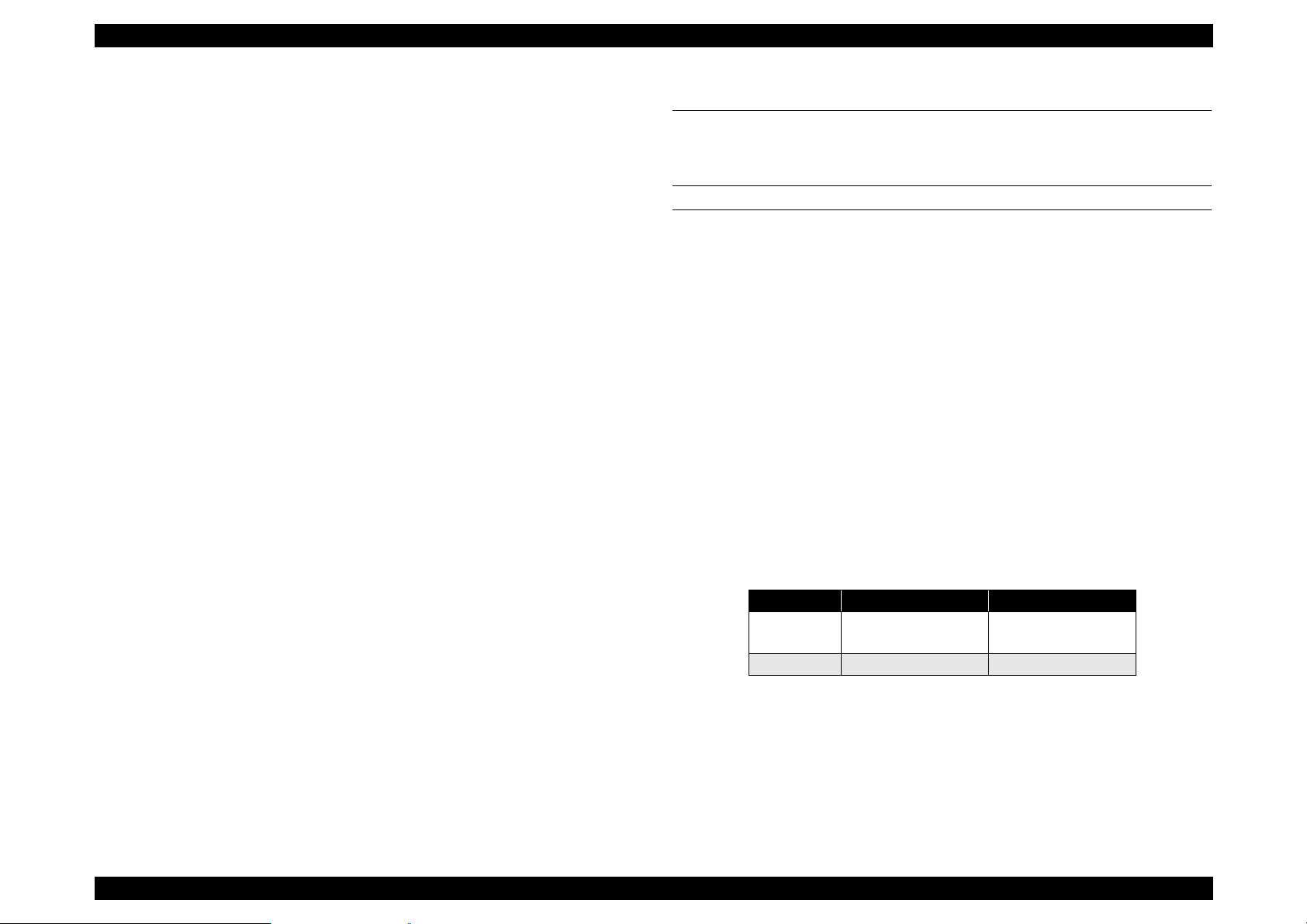
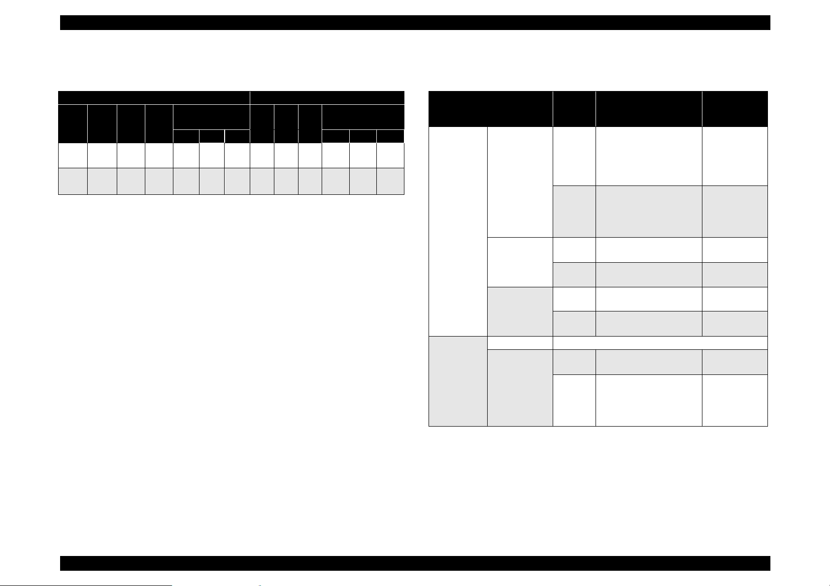
Table 1-1. Maximum Setting
144MB 256MB
CN8/ Slot 0 Standard
16MB
CN9/Slot1 128MB 128MB
128MB
ROM:
Fonts: 2MB (mounted on the main board), 2MB(ROM DIMM
board)
Program: 6MB (mounted on the Flash ROM DIMM board as
4MB +2MB) Main program and PS
Rev.A 3
Page 17

EPSON EPL-N4000 Chapter 1 Product Description
Expansion ROM:1 ROM DIMM slot
C version code and fonts or Local Font or
Flash DIMM can be used.
Host Interfaces:
Standard: Parallel IEEE 1284 compliant, bidirectional, B-type
connector Compatibility, Nibble, ECP
Ethernet 100 BaseTX
Option: Type B slot (1 slot)
Control Panel:
Switch: 8 switches
LED: 6 LEDs
LCD: 20-character LCD
HDD option:IDE type. 2GB(TBD). Dedicated format for EPL-N4000.
Required when finisher option is used. Can only be
used with software version 2.
Miscellaneous:Mechanical control function not built in.
1.2.2 Engine Specification
Printing Method: Electro-photographic printing, utilizing
semiconductor laser beam scan and single-
component magnetic toner.
Resolution: 600 dpi
Printing Speed:
Table 1-2. Printing Speed (PPM)
One-Side Printing Duplex Printing
Size C1 C2
A4
40 38 32
∼
C
L
A3
20 20 19
∼
d
P
LT
40 37 31
∼
L
Note): a:
b.
c:
d:
High Capacity
MP
Tray
a
(16)
(12)
(16)
d
Feeder
C3 C4 C5 C1 C2 C3 C4 C5
38 37 35 28 28 27 26 24 25
20 -- -- 14 14 13 13 -- --
37 36 35 28 28 27 26 24 22
( ) is for custom size(unfixed form).
High(large) Capacity Feeder is optional.
L means long edge first setting.
P means short edge first setting.
High Capacity
MP
Feeder
Tra
y
Rev.A 4
Page 18
EPSON EPL-N4000 Chapter 1 Product Description
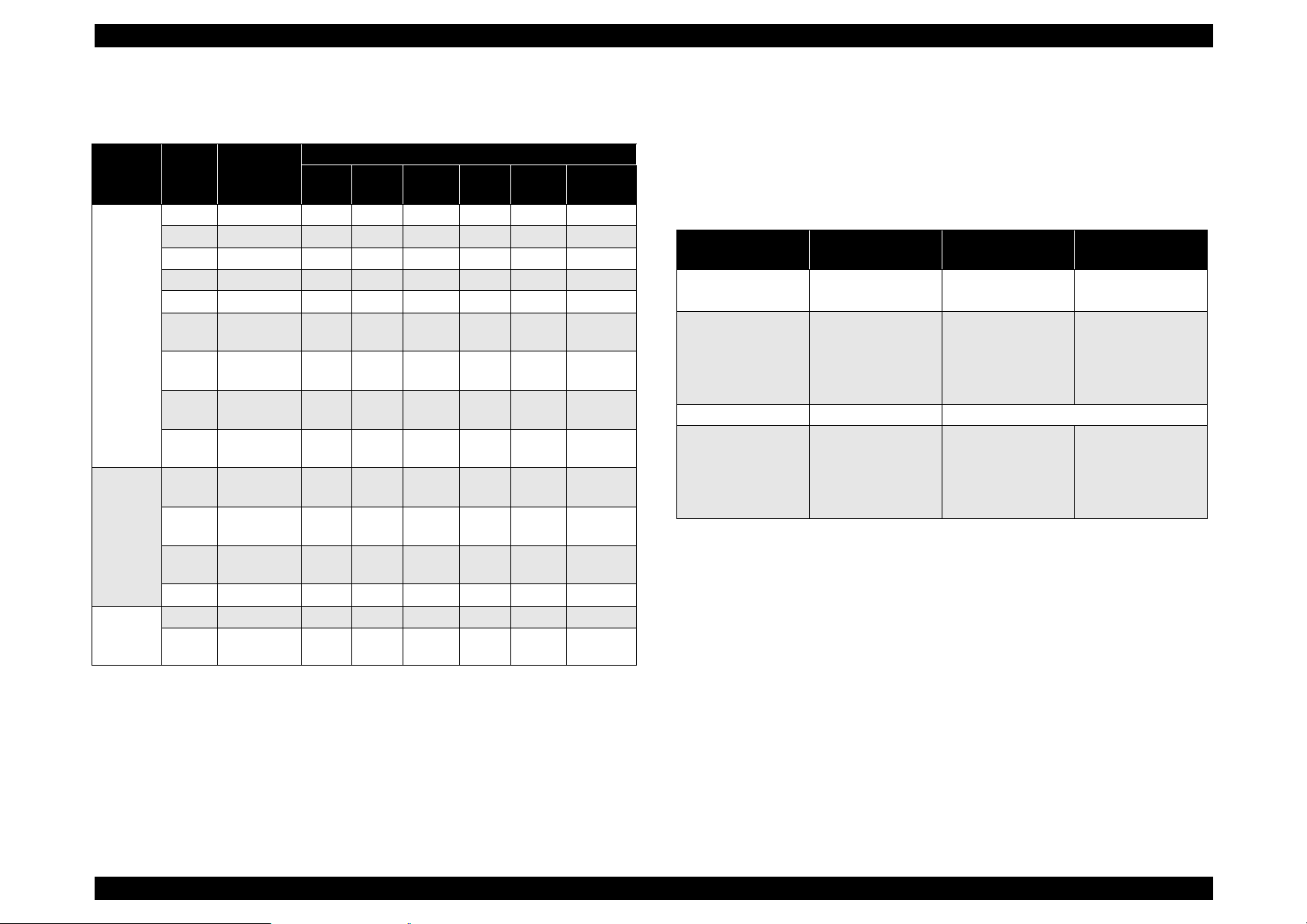
Time to print first sheet
Table 1-3. Time to print first sheet(sec.)
One-Side Printing Duplex Printing
High Capacity
Size C1 C2
10.0 10.8 TBD 11.1 12.0 13.2 14.615.4TBD15.7 16.6 17.8
A4
∼
a
L
LT
10.0 10.8 TBD 11.1 12.0 13.2 14.615.4TBD15.7 16.6 17.8
∼
L
Note): a:
b.
MP
Tray
a
( ) is for custom size(unfixed form).
High(large) Capacity Feeder is optional.
d
Feeder
C3 C4 C5 C1 C2 C3 C4 C5
Warm-Up Time: Within 60 seconds (at 23
1.2.3 Paper Specification
Paper Feeding: Maximum 6 ways.
Paper Feed volume
Standard(No optional parts)
1050 sheets (50 + 500 x 2)
When using optional parts
3550 sheets (Standard + 500 + 1000 x 2)
High Capacity
MP
Feeder
Tra
y
°C/rated voltage)
Feeding Method
Table 1-4. Feeding Method
Paper Feeding Method
Standard MP(Multi
purpose tray)
Cassette 1 500 A3-P, B4-P, A4-L, B5-L,
Cassette 2 500 A3-P, B4-P, A4-L, B5-L,
High
Capacity
Feeder
(Optional)
Cassette 3 Same as Cassette 2
Cassette 4&5 Each
Volume
(sheet)
a
50
5mm
high
TBD Labels, OHP-sheet, thick
TBD Labels, OHP-sheet, thick
1000
TBD Labels, OHP-sheet, thick
Paper Size
• Standard size paper
(A3, B4, F4, Ledger,
Legal, Government
Legal, Executive)
• Custom size paper
A4, B5, A5, Labels,
OHP, Thick Paper,
Letter, Government
Letter, Half-Letter
A5-L
paper, Letter
A5-L
paper, Letter
A3-P, B4-P, A4-L, B5-L,
A5-L
paper, Letter
Paper
thickness
(g/m2)
Normal Paper
60-90
Normal Paper
60-90
Thick Paper
90-190
Normal Paper
60-90
Normal Paper
60-90
Normal Paper
60-90
Normal Paper
60-90
Normal Paper
60-90
Normal Paper
60-90
Thick Paper
90-190
Note):
a.:With 75g/m2 paper.
Rev.A 5
Page 19
EPSON EPL-N4000 Chapter 1 Product Description
Supported paper size: Width=100 to 297 mm
Length=139.7 to 431.8 mm
Table 1-5. Paper Size and Mounting Direction
Paper Feed Standard: Each
Paper Eject
Table 1-6. Paper Eject Volume
Volume
Paper Eject Type
Face down 500 All size, type and
Face down
(Offset)
Face up 200 Same as Face-up
Mailbox 100 sheet x each
Note)
a
: a.Standard function for the face d o wn .
(sheet)
-- Normal Paper
10 mail box
Paper size/Type
Custom size.
(Refer to Table1-4
“Paper Size and
Mounting
Direction”
Normal Paper
(Refer to Table1-4
“Paper Size and
Mounting
Direction”
Offset volume: Approx.20mm
Thickness
2
(g/m
Normal Paper
60-90
Normal Paper
60-90
Thick Paper
90-190
Normal Paper
60-90
)
Paper
Type
Normal
Paper
Normal
Paper
Special
Paper
Mounting Direction
MP
Paper Paper Size
A3 297 x 420 P
A4 210 x 297 L L L L L O
A5 148 x 210 L L -- -- -- -B4 257 x 364 P P P P -- O
B5 182 x 257 L L L L L O
B(LD) 279.4 x
431.8
LG 215.9 x
355.6
GLG 215.9 x
330.2
LT 215.9 x
279.4
GLT 215.9 x
266.7
EXE 184.1 x
266.7
HLT 139.7 x
215.9
F4 210 x 330 P -- -- -- -- O
OHP A4/LT L L L L L -Label A4/LT L L L L L --
Tray
C1 C2 C3 C4,5
a
P P P P -- O
PPPP-- O
P P P P -- O
LLL L L O
L -- -- -- -- O
LLL L L O
L L -- -- -- --
b
P
PP--
c
Duplex
printing
O
d
Note)
: a.L: Long edge first setting.
b.P: Short edge first setting.
c.--: Not available.
d.O: Available.
Rev.A 6
Page 20
EPSON EPL-N4000 Chapter 1 Product Description
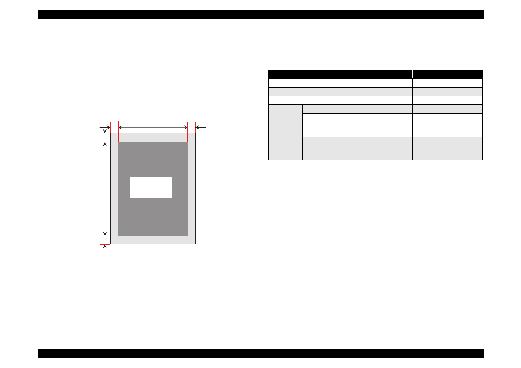
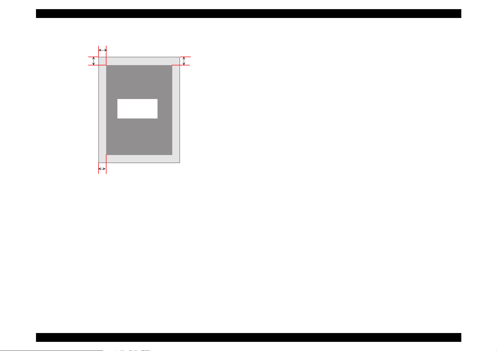
Guaranteed print area
Printable area
297 mm(width) x 431.8 mm(length)
Guaranteed print area
Entire paper area, excluding 4.0 mm from each edge of the
paper.
4m m 4m m
4m m
G uaranteed
print area
1.2.4 Electrical Specification
Power Consumption (printer body)
Table 1-7. Power Consumption
120V 200V
Input Voltage 108
Rated Frequency 50-60Hz±3Hz 50-60Hz±3Hz
Maximum Currency Less than 9.6A Less than 5.2A
Power
Consumpti
on
Maximum Less than1180W Less than 1243W
Continuous
printing
(Average)
Power Saving
(Stand-by)
(Heater Off)
Less than 45W Less than 45W
High Capacity Feeder (Optional)
Average consumption electricity:Less than 0.6 A (24V)
Mailbox (Optional)
Average consumption electricity:Less than 0.6 A (24V)
Maximum: Less than 2.0 A (24V)
Average consumption electricity:Less than 0.2 A (5V)
127V 198 ∼ 254V
∼
TBD TBD
Less than 0.2A (5V)
4m m
Duplex (Optional)
Average consumption electricity:Less than 0.5 A (24 V)
Less than 0.1 A (5V)
Figure 1-2. Printable Area
AC Line Noise:
Pulse width = 50 to 1000 ns
Pulse polarity = +/Repetition = Asynchronous
Modes = Common Normal
Voltage = 1KV (parts must be able to withstand 2KV without
damage)
Rev.A 7
Page 21
EPSON EPL-N4000 Chapter 1 Product Description
Transient Outage: DIP 100% (at rated voltage-10%) 1 cycle
Electrostatic Tolerance: Less than
± 8KV
No damage to image
Surge Current: 1/2-cycle / Not above 100A
Insulation Resistance(TBD): Less than 10 M
Ω
Dielectric Strength: Insulation shall not break down when
the following voltage is applied between
primary circuit and chassis for 1 minute.
Table 1-8. Dielectric strength
Primary-Chassis Primary- Secondary
100/120V AC1000V AC2000V
200 V Series AC1500V AC3000V
Leakage Current: 120V 3.5 mA or less
200V series 3.5 mA or less
1.2.5 Reliability, Durability and Maintainability
MPBF: 400,000 pages (one-side printing)
Print Volume: Maximum 150,000 pages/month
Average 25,000 pages/month
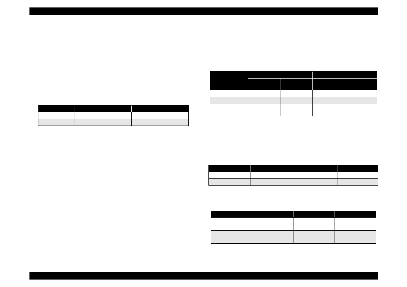
Table 1-9. Paper Feed Reliability
Paper Jam Rate
Standard
Environment
MP Tray 1/200 1/100 1/100 TBD
Cassette1, 2 1/5000 1/2500 1/5000 1/2500
High capacity
feeder, Cassette
Note)
: a.Function for the boundary face, which is caused when the
1/5000 1/2500 1/5000 1/2500
additional papers are added to the paper already set, is not
included. Above figures are based on normal papers.
Printing position reliability
Table 1-10. Printing position
One-side printing duplex printing MP Tray*
Main Scan direction
Sub scan direction
2.0mm
±
1.5mm
±
a
Average of all
environment
Standard
Environment
2.4mm
±
1.9mm
±
Double Feed Rate
Average of all
environment
2.9mm
±
2.1mm
±
Skew (See the figure on next page)
Table 1-11. Skew
One-side printing duplex printing MP Tray*
Main scan direction
( |c-d| )
Sub scan direction
(
a-b| )
|
Note*)
One-side printing.
2.0mm
±
1.5mm
±
2.4mm
±
1.9mm
±
2.9mm
±
2.1mm
±
Rev.A 8
Page 22
EPSON EPL-N4000 Chapter 1 Product Description
c
a
G uaranteed
print area
Bottom
d
b
Figure 1-3. Skew
Product Life: 1500,000 sheets or 5 years in use, whichever comes
first.
Maintenance: MTTR: Average less than 40 minutes.
Rev.A 9
Page 23

EPSON EPL-N4000 Chapter 1 Product Description
1.2.6 Safety Approval
Safety Regulation
Table 1-12. Safety Regulation
Model Applicable Standard
120V • UL1950 2nd Edition
• CSA 22.2 No.950-M95 by UL(=cUL)
200V series • IEC950 2nd Edition with amendment 1(1995)
• CE Directive
Safety Regulation(Laser Radiation)
Table 1-13. Laser Radiation
Model Applicable Standard
120V • FDA21 CFR Chapter1. Subchapter j,Section
1010, 1040.
200V series • IEC 825 Class1 Laser Product
EMC
Power consumption: In compliance with International Energy Star
program.
Ot hers:
Toner: No effect on human health. (In compliance with OSHA,
TSCA, EINECS, worker safety laws and CSCL)
OPC: No effect on human health. (In compliance with OSHA)
Ozone:In compliance with UL478 5th Edition
Materials: In compliance with Swiss environment protection law
(no CdS content)
Table 1-14. EMC
Model Applicable Standard
120V • FCC Parts15 Subpart B, Class B
• CISPR Publication 22, ClassB(Taiwan)
200V series • EN55022 ClassB
• EN61000-3-2
• EN50082-1
• AS 3548 (Australia) (TBD)
Rev.A 10
Page 24

EPSON EPL-N4000 Chapter 1 Product Description
1.2.7 Environmental Specification
1.2.7.1 Operating Environment(including optional parts)
Table 1-15. Operating Condition
Item Condition
Temperature 0 to 32
Humidity 15 to 85%RH (without condensation)
Air Pressure(Altitude) Less than 760 hPa(Less than 2500m)
1.2.7.2 Storage Environment(including optional parts)
Table 1-16. Storage Condition
Item Normal Extreme
Temperature 0 to 35
Humidity 15 to 85%RH Low Humidity: 5 to 15%RH
Storage 12 months Max. 48 hours
C Low Temp.: -10 to 0 °C
°
1.2.7.3 Altitude
C
°
High Temp.:35 to 40 °C
High Humidity:85 to 90% RH
Direction
Three directions(X,Y,Z)
Time
50 minutes in each direction
Storage
0 to 3000m (10000ft)
Transportation
0 to 15000m (49200ft)
1.2.7.4 Vibration Tolerance
Vibration
5 to 100 Hz
Acceleration
0.7G
Rev.A 11
Page 25
EPSON EPL-N4000 Chapter 1 Product Description
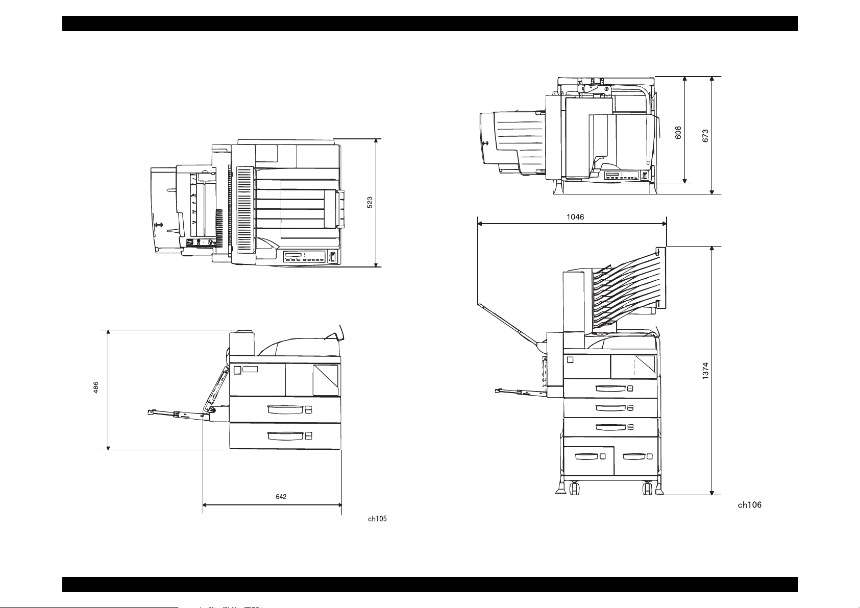
1.2.8 External Dimension and weight
Exterior dimension
642 mm (W) x 523 mm (D) x 486 mm (H) (No optional parts)
Figure 1-4. Exterior Dimension(No optional parts)
Rev.A 12
Figure 1-5. Exterior Dimension(with Mailbox, Duplex unit and High
Capacity Feeder)
Page 26
EPSON EPL-N4000 Chapter 1 Product Description
Weight (No optional parts included)
41.1 Kg (120V)
43.6Kg (200V series)
Optional parts weight
High Capacity Feeder: Less than 35 Kg
Mailbox: Less than 16Kg
Less than 6Kg(Bracket)
Duplex Print Unit: Less than 5.5 Kg
1.2.9 Other Specifications
Noise
Stand-by: Approx. 42(dB)
Operating: Approx. 69(dB)
Ozone Density: Less than 0.02 ppm
Toxicity: OPC, Tonner and plastic materials are all nontoxic.
1.2.10 Consumables
Components and life
Note)*
Toner life is estimated based on continuous printing on A4 size
with 5% print coverage. Toner life will vary according to print
coverage and printing method (continuous or intermittent, print
density, toner-save mode, etc.).
**
This rotation corresponds to approximately 45000 sheets
printing at A4 continuous printing(landscape setting). This OPC
drum life is indicated by minute(s) calculated from the turn on
the engine status sheet.
How to distinguish
Method to distinguish: ID on the cartridge
Type: Check OEM maker and if it is for Japan or for abroad.
1.2.11 Configuration
In the EPL-N4000 controller the following setti ngs can be configured
according to the market destination. The setti ngs are made with jumper
resistors, and must thus be set at the factory.
Table 1-18. Destination-dependent settings
R140 R141 Paper Size Detection
Exist None A4
None Exist Letter
Table 1-17. Cartridge
Name Component Life Weight
ET Cartridge • OPC Drum
• Charging R oller
• Black -Toner
• Cleaner Blade
Life: 20000 sheets*
OPC drum: 130 k turn.**
3.5Kg
Rev.A 13
Page 27
EPSON EPL-N4000 Chapter 1 Product Description
r
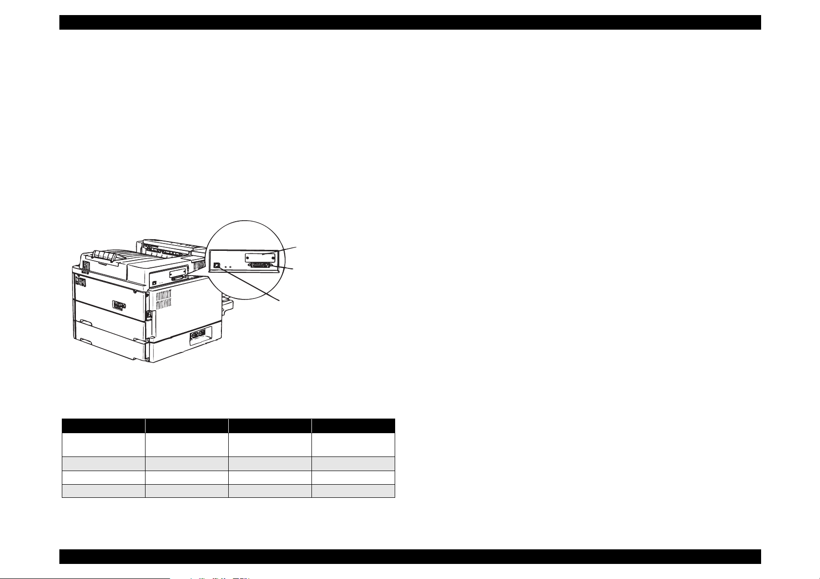
1.2.12 Host Interface Specification
EPL-N4000 has the following interfaces fitted as standard.
IEEE 1284 parallel interface
Ethernet interface
Option Type B interface slot
The following table shows which host interface configurations can be
used.
O ption Type-B Slot
P a r a lle l I/F C o n n e c to
Ethernet I/F C onnector
fig1-2
1.2.12.1 Parallel Interface
Interface type:IEEE 1284 bi-directional parallel interface
Operating mode:Compatibility, Nibble, ECP
Connector type:57RE-40360-830B(D7A)DDK or equivalent
Compatible plug:Amphenole or equivalent
The default device ID setting for this printer is as follows. The
information is shown below including line breaks, but the actual data is
a continuous is shown below includi ng line breaks, but the actual dat a is
a continuous character string, with n o li ne break characters.
MFG:EPSON;
CMD:PJL, ESCPL2-00, ESCP9-84,PRPXL24-01, PCL,
HPGL2-01, ESCPAGE-04
POSTSCRIPT**;
EPL-N4000;
MDL:
CLS:RPINTER;
DES: EPSON EPL-N4000;
Note**
)When optional Post Script board is installed.
Figure 1-6. Interface Part
Table 1-19. Interface
Parallel I/F Ethernet Type-B I/F
I/F automatic
selection
I/F fixed(parallel) O X X
I/F fixed(Ethernet) X O X
I/F fixed (Type-B) X X O
Note)
O: Enable, X: Disable
OOO
Rev.A 14
Page 28
EPSON EPL-N4000 Chapter 1 Product Description
1 8
ch103
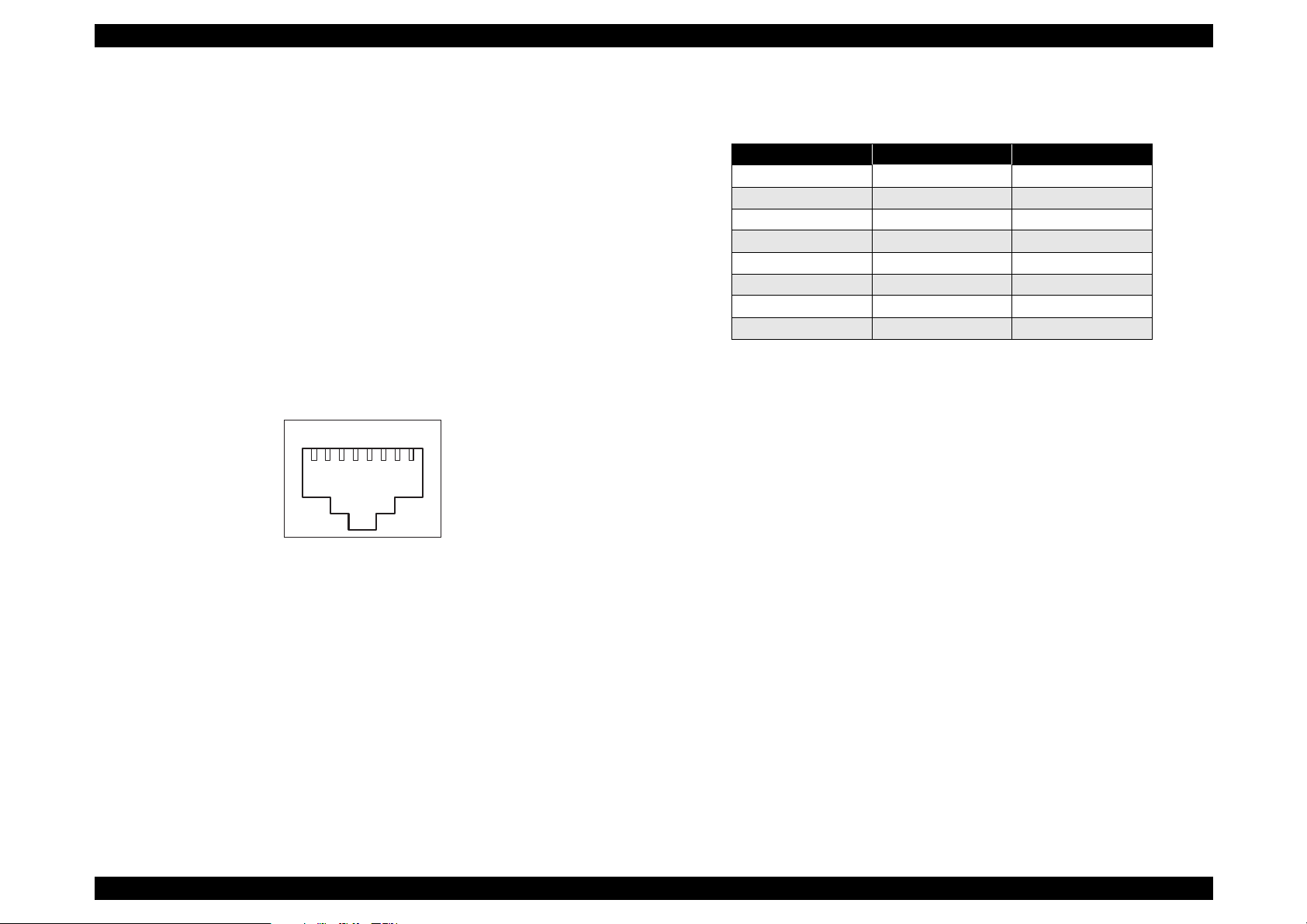
1.2.12.2 Ethernet Interface Specification
Interface type:10BaseT, 100BaseT automatic switching
Communication protocol
IPX/SPX(IPX, SPX, NCP, RIP, SAP, PrintServer,
RemotePrinter, NDS, SNMP)
NetBIOS(SMB), NetBEUI not supported
TCP/IP (IP, UDP, TCP, LPR, FTP, TENET, ARP, ICMP, RARP,
BOOTP, DHCP, SNMP, HTTP)
Apple Talk (ELAP, DDP, ATP, PAP, AARP, NBP, ZIP, RTMP)
Connector type:RJ45
Pin Assignment
Table 1-20. Pin Assignment
Pin Signal I/O
1Tx+O
2Tx- O
3Rx+I
4N.C. --5N.C.--6 Rx- I
7N.C.--8N.C. ---
1.2.12.3 Type-B Interface
This printer is fitted as standard with a Type B option slot.
Main system type:MTP600dpi, PW7016dt600dpi, PRG(****)rev,
Ap500ma, SPD0fast.
Note)
**** is ROM version.
Appropriate cable:2-pair Category 3 or 4 or 5 UTP(10 BaseT,
Rev.A 15
100BaseT)
Figure 1-7. RJ45 Connector/Pin Position
Printer Name: Factory default setting is same as Product Name
Product Name: EPL-N4000
Page 29
EPSON EPL-N4000 Chapter 1 Product Description
1.3 OPERATION
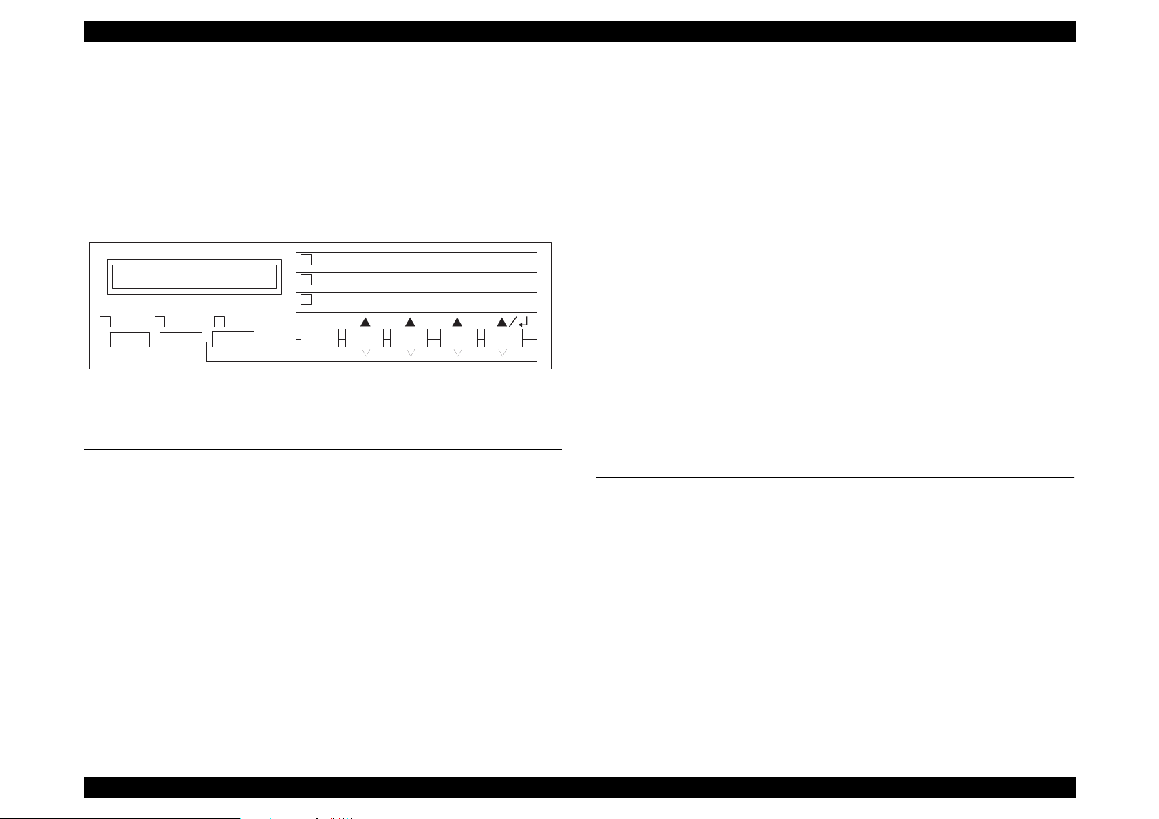
1.3.1 Control Panel
The control panel of this printer has one display, 6 LEDs and 8
switches. Figure below shows exterior view of the control panel.
Paper S ource P aper Size M anual Feed O rientation
RITech Copies M P Tray Size
M e n u Ite m V a lu e E n te r
O n-Line Form Feed Continue
Reset ALT
Select Type
Figure 1-8. Control Panel
LCD DISPLAY
Specification:20 characters in one line (5x7 dot matrix)
Function: Usually, It displays printer condition. In case of panel
setting mode, setting is performed by the indication.
LED LIGHTS
On Line LED(green):On = Printer is ready for printing.
Off = Printer is not ready.
Toner Save
M o d e
Off = No effective recei ved data is left in the
printer. But if the control code is not ended, LED
is still On.
Blinking = Processing the data.
Error(red): Error happens and it can be canceled by
Continue switch.
“One-Touch” Setting Mode 1 LED (green):
On = indicates that “One-Touch” setting mode
1 is selected. 4 items can be set; Paper
Source, Selection, Paper size, Manual Feed,
and Orientation.
“One- Touch” Setting Mode 2 LED (green)
On = indicates that “One-Touch” setting mode
2 is selected. 4 items can be set ; RITec h, Copi es,
MP Tray paper size and Toner Save Mode.
Select Type Mode LED(green)
On = indicates that the printer is in the select
type panel setting mode.
SWITCHES
On-line: The printer goes to by pressing this button when the
printer is in the on-l ine(ready) status. Pressing th is butt on
during the panel setting, the printer escapes from the
panel setting mode and immediately goes to the Online(ready) mode.
Data(yellow): On = Received data is not printed out and still left
in the printer. But if the received data except
effective printing data is left, LED does not turn
on.
Rev.A 16
Page 30

EPSON EPL-N4000 Chapter 1 Product Description
CAUTION
Form Feed:If Data light is On in the not-ready condition, the
printer prints the received data on the one sheet by
pressing this button. If the plural numbers of printing is
selected, the printer prints out that number.
In case of the data which the control code has not
ended yet, the printer prints out the data, which has
already received. However, if the data light is off, the
printer does not eject the paper.
This printer has EEPROM and hard disk drive HDD
inside and records various setting values and
printing data. If the printer is turned off during this
process, writing operation is not guaranteed, and
error occurs when the printer is turned on next time.
Therefore, never turn off the printer at the following
cases;
Continue: Error is canceled by pressing this button, while the
Continue LED light is on. When warning occurs,
warning indication is canceled by pressing this button.
Select type/Alt switch:Ordinary condition, One-touch setti ng mode1,
2 and select type mode.
•
From the power on to On-line light on.
•
On-line light is blinking
•
When the printer is printing(when the paper
transporting motor is in active)
When you want to stop printing, press “On-line
switch” or perform Job Cancel/Reset.
Menu switch: The printer goes to the setting mode by
pressing this switch.
Each switch operation for the panel setting is on the next page.
Item switch: The printer goes to the previous setting item
by pressing this switch.
Value selection switch:The printer goes to the previous setting item
by pressing this switch.
Enter switch: By pressing this button, the printer goes to
status sheet in the test printing menu.
Reset(Continue): The printer stops printing or resets by
pressing Alt and Continue switches. After
displaying “Reset” on the display, pressing
both switches for 5 seconds lead to “Reset
All” and executes warm boot.
Rev.A 17
Page 31

EPSON EPL-N4000 Chapter 1 Product Description
Each switch operation for the panel setting is as follows.
Table 1-21. Switch operation for the panel setting
On-line
Switch
(ready)
Panel setting Goes to Not
ready status
and enters to
One-touch
setting mode1.
Setting menu Goes to select
type mode
Alt + setting
Invalid Invalid Menu selection
menu
Item selection Goes to the
previous
setting mode.
Alt + item
Invalid Invalid Item selection
selection
Not-ready
Goes to “Onetouch” setting
mode1.
Goes to select
type mode.
Goes to the
previous
setting mode.
Panel Setting
mode
Escape from
the panel
setting mode,
and goes to
On-line status.
Menu selection
(indicates next
setting
2
menu)*
(indicates
previous
setting
2
menu)*
Item selection
(next setting
item is
displayed)
(previous
setting item is
displayed)
Panel setting
(one touch
mode)
Goes to the next
panel setting
mode.
Paper selection
(one-touch
mode1), Printer
mode
selection(onetouch mode2)*
2
Paper selection
(one-touch
mode1), Printer
mode
selection(onetouch mode2)*
2
Paper size
selection (onetouch mode1),
Printer mode
selection(onetouch mode2)
Paper size
selection (onetouch mode1),
Printer mode
selection(onetouch mode2)*
2
Table 1-22. Switch operation for the panel setting
Panel setting
On-line
Switch
Value
selection
Alt + Value
(ready)
Goes to the
previous item.
Invalid Invalid Displays the
selection
Enter Goes to the
item of the
status sheet.
Not-ready
Goes to the
previous item.
Goes to the
item of the
status sheet.
Panel Setting
mode
Displays next
setting
2
value.*
previous
2
item.*
Confirm the
setting value.
Prints out or
perform
processing.
Alt + Enter Invalid Invalid Invalid Paper direction
(one touch
mode)
Minification
selection (one
touch mode1),
Tray paper size
selection(one
touch mode2)*
Minification
selection (one
touch mode1),
Tray paper size
selection(one
touch mode2)
[indicates the
previous setting
2
value]*
Paper direction
selection(one
touch mode1),
Toner saving
selection(one
touch mode2)*
selection(one
touch mode1),
Toner saving*/
(one touch
mode2). [indicates
previous setting
2
value] *
2
2
Note)
* When using duplex print function, sele ct “Duplex” instead of
“Toner Save”.
2
If you keep pressing, it will be repeat input.
*
Rev.A 18
Page 32

EPSON EPL-N4000 Chapter 1 Product Description
1.3.2 Panel Setting Mode
Here explains panel setting mode which sets various function of the
printer.
1.3.2.1 One Touch Setting Mode
By pressing Select Type(ALT) switch on the control panel, the pr inter
enters to the one-touch setting mode1, then goes to the one-touch setting mode 2. Setting items at each setting mode are mentioned below.
Table 1-23. One touch setting modes
Mode/Switch Setting Menu Setting Item Setting Value Enter
One touch
setting mode1
One touch
setting mode2
Paper source Page size Manual Feed Orientation
Printer mode Copies MP tray size Duplex
1.3.2.2 List of Setting Items
The following is a list of the printer setting items. Note that the box in the
“Value” column indicates the factory default setting.
Table 1-24. Printer Setting
Menu Item Value
Test Menu • Status sheet
• ESC/Page F ont Sample.
*29
*2
.
*2
• ESC/Page
LJ5
*56
, ESCPC*2, PageC*2,
, ESCP2, FX, I239X, PS, GL2,
Auto
•
ESC/Page
LJ5
• ESC/Page
LJ5
*56
, ESCPC*2, PageC,
, I239X, PS, GL2,
*56
, ESCPC*2, PageC*2,
AUTO
, ESCP2, FX, I239X, PS, GL2,
Auto
•
•
Auto
LC3
A4
*41
, MP
*42
, LC4
*6
, A3, A5, B4,
, ENV
*42
, LC5
*40
, LC1, LC2,
*7
, B, HLT, LGL,
LT
GLT, GLG, EXE, F4, MON, C10,
DL, C5, IB5, CTM, 8VO*2, 16MO
*2
Emulation
Menu
Printing
Menu
• ESCPC Font Sample
• PageC Font Sample
• LJ5 Font Sample.
• ESCP2 Font Sample.
• FX Font S ample
• 1239X Front Sample.
• PS Status Sheet
• PS Font Sample
• PS Fact Sheet
• Ext Printer Info
• Parallel
•Ethernet
*8
•AUX
• Paper Source
• Page Size
•
ON
•Wide A4
• Orientation
Off,
•
, Land
Port
Rev.A 19
Page 33

EPSON EPL-N4000 Chapter 1 Product Description
Å
Table 1-25. Printer Setting Table 1-26. Printer Setting
Menu Item Value
Printing
Menu
•Copies
• Quantity
*55
• Manual Feed
• Out Bin
•1-999
•
-999
1
•
, On
Off
•
Face Down
Mailbox 1
*53
300
On
, Back
On
, Staple
, Right
*6
, A3, A5, B4,
Tray Size
Menu
• Resolution
•Duplex
• Binding
• Start Page
*21
*21
*21
•Shift
•Finish
*50
• Staple position
• MP Tray Size
*50
Mailbox3
•
600,
•
Off,
•
Long Edge
•
Front
•
Off,
•
None
•
Left
•
A4
GLT, GLG, EXE, F4, MON, C10,
DL, C5, C6, IB5, 8VO*2, 16MO
•
DL, C10, C6, MON
• ENV Tray size
•LC1 Size
•LC2 Size
•LC3 Size
•LC4 Size
•LC5 Size
•MP Type
*43
*43
*44
*44
*44
*41
*40
C5,
•A4, A3, A5, B4, LT, HLT, LGL,GLG,
B, EXE
• A4, A3, B4, LT, B, LGL, GLG, EXE
• A4, A3, B4, LT, B, LGL, GLG, EXE
• A4, LT, EXE
• A4, LT, EXE
•
, Preprinted, Letterhead,
Plain
Prepunched, Bond, Recycled,
Color, Transparency, Labels
• LC1 Type
• LC2 Type
• LC3 Type
•
•
•
*42
, Preprinted, Letterhead,
Plain
Prepunched, Bond, Recycled, Color
Preprinted, Letterhead
Plain,
Prepunched, Bond, Recycled, Color
, Preprinted, Letterhead
Plain
Prepunched, Bond, Recycled, Color
, Face up
*53
, Mailbox2
*53
to 10
, Short Edge
LT
*51
, Stacker
*53
,
.
*7
, B, HLT, LGL,
*52
,
*2
Menu Item Value
Tray Size • LC4 Type
*42
•
, Preprinted, Letterhead
Plain
Prepunched, Bond, Recycled, Color
, Preprinted, Letterhead
Plain
Prepunched, Bond, Recycled, Color
, Off.
On
, On.
Off
4, 5, 1, 2
3,
, -99.0 mm step 0.5mm.
0.0
to 30mm step 1mm
0
On
Off,
On
Off,
, On
Auto
, Off, On
Auto
Normal
Auto
Enable
English
Off
Off
, Thin, Thick
, Parallel,Ethernet, AUX*8.
, Disable
,
, On
, On
• LC5 Type
Config Menu •RITech
• Toner Save
•Density
• Top Offset, Left Offset
• Back Shift
• Size Igno re
• Auto Count
• Page Protect
• Image Optimum
• Paper Type
Setup Menu • Interface
• Time Out
• Standby
• Language
• Lang
• Sprache
•LINGUA
• LENG
• SPR
K
•Sprog
•Taal
• LANG
•Ling
• Panel Lock
• Printer Name
• Toner
*19
*42
*21
*22
•
•
•
•
•-9.0, -
•
•
•
•
•
•
•
•0, 5-60-300 step1
•
•
• Francais
•Deutsch
•ITALIANO
• ESPANOL
• SVENSKA
•Dansk
• Nederl.
• SUOMI,
• Portugues.
•
•
• E****F, E***¨F, E**¨¨F, E*¨¨¨F, E¨¨¨¨F
Rev.A 20
Page 34

EPSON EPL-N4000 Chapter 1 Product Description
g
Table 1-27. Printer Setting Table 1-28. Printer Setting
Menu Item Value
Setup Menu • Page count
*19
• 0 to 99999999
• SelecType Init
Parallel Menu • Speed
•Bi-D
• Buffer Size
Ethernet
Menu
• Buffer Size
• IP Byte 1
• IP Byte 2
• IP Byte 3
• IP Byte 4
• SM Byte 1
• SM Byte 2
• SM Byte 3
• SM Byte 4
• GW Byte1
• GW Byte2
• GW Byte3
• GW Byte4
*56
*8
• Buffer Size •
•Auto CR
•Auto FF
AUX Menu
ESC/Page
Menu
• CR Function
• LF Function
• FF Function
• Error Code
• Image Correct
• Page Scale
• Avoid Error
• Form Overlay
• Form Number
*58
*58
*58
*58
*57
*57
•
•
•
•
Normal
Fast,
Nibble
Normal
Normal
•0 to 255
•0 to 255
•
to 255
0
•0 to 255
•0 to 255
•
to 255
0
•0 to 255
•0 to 255
•
0 to 255
192,
•0 to 255
•0 to 255
•
, 0 to 255
192
Normal,
•
, Off
On
•
Off
On,
•
CR+LF
CR,
•
LF+CR,
•
FF+CR
•
Ignore,
•1, 2
•
100%,
•
, On
Off
•
, On
Off
•1 to 152
, ECP, Off
, Maximum, Minimum
, Maximum, Minimum
Maximum, Minimu m
LF
, FF
Space
80%, 70%
Menu Item Value
ESCPC
*2
• Font Ascii
•
Courier
, Roman, Sans ser, Prestige,
Script, Orator S, OCR A, OCR B
•Font Hanji
• Hanji Mode
• Hanji Code
•Pitch
• Condensed
• T. Margin
•Text
• Margin Max
• CGTable
•
•
•
•
•
•
•
•
•
, Hei, Yuang, Kai, Li
Sun
Off
On,
, TCA, BIG5, IBM5550
NS
, 12cpi, 15cpi, Prop.
10cpi
, On
Off
, 0.40 to 1.50 inch step 0.05 inch
0.45
1 to 135 lines
66,
Default
PcUSA
, PaperSize
, Italic, PcMultilin, PcPortugue,
PcCanFrenc, PcNordic, Pc Turkish2,
• Country
PcE.Europe, BpBRASCII, BpAbicomp
•
France, Germany, UK Denmark,
USA,
Sweden, Italy, Spain1, Japan, Norway,
Denmark2, Spain2, LatinAmeric, Korea,
Legal
PageC
•Auto CR
• Auto LF
•Bit Image
• ESCPC Scale
• Avoid Error
*2
•Auto CR
•Auto FF
• CR Function
• LF Function
• FF Function
• Error Code
• PageC Scale
• Avoid Error
•Form Overlay
• Form Number
*57
*57
*57
•
On
•
Off,
•
Dark
•
100%,
•
Off
•
On,
•
On,
•
CR
•
LF + CR
•
FF + CR,
•
Ignore
•
100%,
•
Off
•
Off
•
Resident
, Off
On
, Light, BarCode
80%, 70%, 60%
, On
Off
Off
, R+LF
, LF
FF
, Space
80%, 70%
, On
, On
, DIMM, Download
Rev.A 21
Page 35

EPSON EPL-N4000 Chapter 1 Product Description
Table 1-30. Printer Setting
Table 1-29. Printer Setting
Menu Item Value
LJ5 Menu • Font Source
• Font Number
•Pitch
•Height
• SymSet
•Form
• Source SymSet
•Dest SymSet
*7
•
Resident,
•
∼ available(Max 65535)
0
•0.44∼
•4.00∼
•
10.00
12.00
IBM-US
, Roman-8, ECM94-1,
8859-2 ISO, 8859-9 ISO, 8859-9
ISO, 8859-10ISO, PcBlt775, IBMDN, PcMuktiling, PcE. Europe,
PcTk437, Pc1004, WiAnsi,
WiE.Europe, WiTurkish, WiBaltic,
DeskTop, PsText, VeInternati,
VeUS, MsPublishin, Math-8,
PsMath, VeMath, PiFont, Legal,
UK, ANSI ASCII, Swedis2, Intalian,
Spanish, German,Norweg1,
Fench2, Windows, McText,
PcIcelandic
PcTurk2
PcS1437
ISO
*14*24
*14
*14
, 8859-4 ISO
WiEstonian
Mazowia
*14*27
BpBRASCII
PcGk37
*14*25
PcGK869
WiGreek
PcCy855
PcLt866
WiCyrillic
*14
*14*26
*14
*14
PcUkr866
*14
, Hebrew8
ISO
Arabic8
ISO
•60*7,
•
277,
•
277,
*14
*14
, OCR A
*6
,5 to 128 lines
64
0 to 3199
0 to 3199
DIMM, Download.
∼99.99 cpi step 0.01 cpi
∼999.75pt step 0.25 pt
*14
, PcLt774
, PcCanFrench
, PcNordic
*14
, WiLatvian
, CodeMJK
*14
, BpAbicomp
, PcGk851
*14*25
, 8859-7 ISO
, Europe3
, PcCy866
, 8859-5 ISO
, Bulgarian
*14
, Hebrew7
, PcAr864
*14
*14
*14
, WiBaltic
*14
*14*26
*14
, PcHe862
*14
, 8859-6
, OCR B
*14
,
, 8859-3
*14
,
*14*27
*14
*14
,
*14*25
,
*14*26
*14
,
,
*14
, 8859-8
*14
*14
,
,
,
*14
,
*14
,
,
,
Menu Item Value
GL2 Menu • GL-Mode
•Scale
•Origin
•Pen
•End
•Join
• GLlike,
•
, A0, A1, A2, A3
Off
•
Corner,
•
•
•
, Pen1, Pen2*6, Pen3*6, Pen4*6,
Pen0
*6
Pen5
Square, Triangular, Round.
Butt,
Mitered
LJ5GL2
Center
, Pen6
, Miteredbeveled. Triangular,
Round, Beveled, None.
•Pen0
•Pen1
•Pen2
•Pen3
•Pen4
•Pen5
•Pen6
*16
*16
*16
*16
*16
PS Menu • Error Sheet
• Protect Level
ESCP2 Menu • Font
•0.05∼
•0.05∼
•0.05∼
•0.05∼
•0.05∼
•0.05∼
•0.05∼
•
Off
•1∼5
•
Courier,
∼5.00mm step 0.05mm.
0.35
∼5.00mm step 0.05mm.
0.35
∼5.00mm step 0.05mm.
0.35
∼5.00mm step 0.05mm.
0.35
∼5.00mm step 0.05mm.
0.35
∼5.00mm step 0.05mm.
0.35
∼5.00mm step 0.05mm.
0.35
, On
Prestige, Roman, Sans, serif,
Roman T, Orator S, Sans H, Script,
OCR A, OCR B.
•Pitch
• Condensed
• T. Margin
•Text
• CGTable
•
•
•0.40∼
•1∼
•
, 12cpi, 15cpi, Prop.
10cpi
On
Off,
∼1.50 inch step 0.05 inch
0.50
*7
*6
62
PcUSA
∼available (Max 111) Lines
66
, Italic, PcMultiln, PcPortugue,
PcCanFrenc, PcNordic, PcTurkish2,
PcE. Europe, BpBRASCII, BpAbicomp,
*14
PcS1437
PcIcelandic
Mazowia
PcGk437
8859-7 ISO
Bulgarian
Hebrew8
, PcTurkish1
*14
*14
, CodeMJK
*14
,PcGk851
*14
*14
*14
, PcAr864
*6
, 8859-9 ISO
, PcCy855
, PcUkr866
*14
,
*14
*14
,
*14
, PcGk869
*14
, PcCy866
*14
, Hebrew7
*14
, PcHe862
,
*14
,
*14
*14
,
*14
,
Rev.A 22
Page 36

EPSON EPL-N4000 Chapter 1 Product Description
Table 1-31. Printer Setting Table 1-32. Information Control and its Method
Menu Ite m Value
ESCP2 Menu
(Cont.)
• Country
•
France, Germany, UK, Denmark,
USA,
Sweden, Italy, Spain1, Japan, Norway,
Denmark2, Spain2, LatinAmeric, Korea,
Legal.
•
Off
•Auto CR
• Auto LF
•Bit Image
• ZeroChar
FX Menu •Font
On,
•
Off,
•
Dark
•
0
•
Courier
On
, Light, BarCode
,
φ
, Prestige, Roman, Sans serif,
Script, Orator S, OCR A, OCR B
•Pitch
• Condensed
• T. Margin
•Text
• CGTable
•
•
•0.40
•1
•
, 12cpi, 15cpi, Prop.
10cpi
On
Off,
1.50 inch step 0.05 inch
∼
∼
0.50
*17
*16
∼
62
66
, Italic, PcMultiln, PcPortugue,
PcUSA
PcCanFrenc, PcNordic, PcTurkish2,
PcE. Europe, BpBRASCII, BpAbicomp
• Country
•
France, Germany, UK, Denmark,
USA,
Sweden, Italy, Spain1, Japan, Norway,
Denmark2, Spain2, LatinAmeric
•Auto CR
• Auto LF
•Bit Image
• ZeroChar
1329X Menu • Font
•
On,
•
Off,
•
Dark
•0,
•
Courier
Off
On
, Light, BarCode
φ
, Prestige, Roman, Sans serif,
Script, Orator S, OCR A, OCR B
•Pitch
•
, 12cpi, 15cpi, 17cpi, 20cpi,
10cpi
24cpi,Prop.
•
850, 860, 863, 865
• Code Page
• T. Margin
•Text
•Auto CR
• Auto LF
• Alt.Graphics
437,
•
, 0.30 to 1.50 inch step 0.05 inch
0.40
•63*7,
•
Off,
•
Off,
•
Off,
*6
, 1 to available (Max:111) Lines
67
On
On
On
available (Max 81) Lines
∼
Menu Item Value
1239X Menu • Bit Image
• ZeroChar
• CharacterSet
•Mode
• Mailbox1
• Mailbox2
• Mailbox3
• Mailbox4
• Mailbox5
• Mailbox6
• Mailbox7
• Mailbox8
Maintenance
62
Menu*
• Engine Status Sheet
• Total Counter Clear
•
•
•1*7,
•
• 24byte
• 24byte
• 24byte
• 24byte
• 24byte
• 24byte
• 24byte
• 24byte
, Light, BarCode
Dark
,
φ
0
*6
2
Sorter,
Mailbox, Stacker, JpbSeparator
• Fuser Counter Clear
• LC1 Counter Clear
• LC2 Counter Clear
• LC3 Counter Clear*
• LC4 Counter Clear*
• LC5 Counter Clear*
75
75
75
• MP Counter Clear
• TR Counter Clear
• DM Counter Clear*
75
• FD Counter Clear
• FU Counter Clera*
• MB Counter Clear*
• Fin Counter Clear*
75
75
75
• Staple Count
75
Clear*
• Error Log Clear
Note)
Refer to the next page.
Rev.A 23
Page 37

EPSON EPL-N4000 Chapter 1 Product Description
;
Note)
*2: Appears only in C version.
*6: Fac tory default setting for Europe and Pacific models.
*26Appears only when NLSP EDG OEM Scala ble Font ROM for Cyr illic
installed.
*27Appears only when only when NLSP EDG OEM Scalable Font ROM
for Latin installed.
*7: Fac tory default setting for North America models.
*8: Can onl y be selected when TypeB I/F option is installed.
*9: Fac tory default setting for C version.
*12Indication depends on the cassette install ed.
*13Appears only when DCI font ROM DIMM or font card installed.
*14Appears only when NLSP Bitmap3 Font ROM installed.
*16Appears only in GLlike mode.
*18When a status sheet resource is included in NLSP Font ROM, ROM
DIMM, according to the lower diagram, Lang=Option1, Option2,
Option8 can be selected. The setting items and values appear in
English.
*19This item is for display only, and the setting cannot be changed.
*21Appears only when the optional duplex unit is installed.
*28When LJ4 Menu→SymSet Value is changed to this Symbol set,
Font Source= Resident, Font Number=0 setting is automatically
made, and therefore to print this symbol set, a font must be
selected for which the Font Source and Font Number Value are
supported by this symbol set.
*29Appears when a status sheet resource is included in NLSP Font
ROM.
*33Appears only when the relevant option font is installed.
*40Appears only when the ENV tray is installed, and can then be
selected.
*41Does not appear if the ENV tray is installed. It is assumed that the
power is off during the installation.
*42Appears only when the high-capacity lower cassette is installed, and
can then be selected.
*43Not displayed on the panel. Can be extracted with EJL and so forth.
Not printed on the status sheet.
*22Not displayed on the LCD.
*24Appears only when NLSP EDG OEM schedule Font ROM for
Turkish installed.
*25Appears only when NLSP EDG OEM Scalable Font ROM for Greek
installed.
*44Not displayed on the panel. Can be extracted with EJL and so
forthonly when the high-capacity lower cassette is installed. Not
printed on the status sheet.
*50Not displayed on the panel. Not printed on the status sheet. Can be
selected and obtained with PJL, EJL, and so forth only when the
finisher is installed.
Rev.A 24
Page 38

EPSON EPL-N4000 Chapter 1 Product Description
*51Appears only when the face-up tray is installed, and can then be
selected.
*52Appears only when the multibin unit or fini sher is installed, and
printer is in stacker mode or job separator mode; can then be
selected.
*53Appears only when the multibin unit or fini sher is installed, and
printer is in mailbox mode: can then be se lected. If the finisher, from
mail box 1 to 3.
*54Not displayed on the panel. Can be selected and obtained with
warm boot. Possible operations are limited.
No option: Sorter
Multibin unit: Sorter, Mailbox, Stacker, Job Separator
Finisher: Mailbox, Stacker
*55Not displayed on the panel. Not printed on the status sheet. Can be
set with EJL, PJL and so forth. Not saved in NVRAM.
*56Not displayed on the panel of the C version.
*57Appears only when content s inf ormation data is written i n t he DIMM
installed; can then be selected.
*58Not displayed on the panel. Not printed on the status sheet. Can be
selected or obtained with EJL.
*62 Appears only when Maintenance Menu becomes available by the
hidden operation at Power On; can then be selected.
*75 Appears regardless of the installati on of optional parts. Counter
Clear can be also carried out.
Rev.A 25
Page 39

EPSON EPL-N4000 Chapter 1 Product Description
g
g
g
g
g
g
g
g
g
g
g
g
g
CAUTION
CAUTION
1.3.3 Special Operation
Here expla ins functions wh ich are operated by the special operation of
the switches on the control panel. Following functions are activated by
pressin
power on.
CAUTION
a particular button before RAM check is completed after the
Please handle carefully the information written i n this
section. Special operation mentioned here are not
opened to the users, since the service man with
professional knowledge should perform these
operation.
Hexadecimal Damp
Received data is converted to hexadecimal ASCII, then it is output.
It is effective for all interfaces.
Operation
Turn on the power, pressin
Cancel
Perform Warm boot by pressin
the power off and on a
“Form Feed” switch.
Reset(Continue) switch, or turn
ain.
Turn on the power, pressin
“On-line” switch, “Continue” switch
and “Menu” switch.
Total Counter, Tray Counter and Transfer Roller
Counter, which are recorded by the engine
controller, are not initialized. However, Page
Counter, which is recorded by the Video
Controller(C262 Main Controller) is reset.
Initialization of the Panel Settin
This function returns all the panel settin
Value
to the factory setting.
(common environment, I/F environment). After that, the printer
performs warm boot and returns to the normal state.
Operation
Turn on the power, pressin
All the values which can be set by the user, are
“Continue” switch.
initialized.
Values which can be changed by the printing
operation or maintenance operation, are not
initialized.
Initialization of EEPROM
All values, which are stored in the EEPROM at the controller side,
are initialized and returned back to the factory settin
initialization, the printer perform warm boot and
. After this
oes back to the
normal state.
Forced erasin
the Flash ROM Module
This operation erases the content of the flash ROM module, which
is connected to A slot DIMM ROM Module on the main board.
Operation:
Turn on the power, pressin
switch and “Enter” swi tch. Erasi n
“Alt” switch, “Item” switch, “Value”
starts after “Erasing DIMM A”
is indicated. After that, the printer performs warm boot and
returns to the normal state.
Rev.A 26
Page 40

EPSON EPL-N4000 Chapter 1 Product Description
Toner Reset
Program ROM Up Date
This function updates program DIMM, which is connected to the
program socket on the main board.
Operation
Turn the power on, pressing “On-Line” switch, “Alt” switch and
“Value” switch.
Copy of ROM Module
This function copies the content of ROM module inserted to B
socket on the main board to the flash ROM module inserted to A
socket. Also, if ROM module is not inserted to B socket, the printer
copies the content of ROM module, which is inserted to code ROM
socket.
Operation:
Turn the power on, pressing “On-Line” switch, “Alt” switch and
“Enter” switch. By pressing “Enter” switch at the point that LCD
displays “DIMM COPY MODE”, the printer copies after erasing
Flash ROM. After that, the printer performs warm boot and
returns to the normal condition.
This function sets the toner left quantity FULL.
Turn on the power, pressing “On-line switch” and “Form Feed”
switch.
Duplex Test Print
After “Duples Test Print” is added to the next item of “status” on the
test menu of the panel setting, this duplex test print will be able to
execute. Pressing “Enter” switch, “Item” switch and “Enter” switch
can also execute this function. This functi on is not indicated when
the duples unit is not install ed. Paper si ze and pri nt environment are
processed in the same way as printing the status sheet.
Operation
Turn the power on, pressing “On-line” switch, “Alt” switch and
“Item” switch.
Rev.A 27
Page 41

EPSON EPL-N4000 Chapter 1 Product Description
1.3.4 Maintenance Mode
Maintenance menu is added to the setting menu, then, the printer
performs warm boot and enable to execute the maintenance menu.
(See Table 1-24, “Printer Setting,” on page 19)
1.3.4.1 Operation
Turn the power on, pressing “On-Line” switch “Form Feed” and
“Continue” switches.
CAUTION
Toner Counter Clear
This function is executed when Total Counter needs to be 0.
Since the total print volume which is indicated on the status sheet
and control panel is independent, it never becomes 0.
Fuser Counter
This function is performed when the toner is exchanged. Fuser
Counter on the engine status sheet becomes 0 and +1 is added
when the fuser is exchanged.
LC1
This function is performed when each Feed Roller Set in casset tes 1
to 5 is exchanged. Each corresponding LC(1 to 5) counter on the
engine status sheet becomes 0 and+1 is added when the feed
roller set is changed.
In the maintenance mode, since the service require
error is ignored, make sure that there is no error
signs when you need to print out something, such as
Engine status sheet.
∼5 Counter Clear
MP Counter Clear
This function is performed when the Feed Roller of the tray is
exchanged. MP counter on the status sheet becomes 0 and +1 is
added when the roller is exchanged.
TR Counter Clear
This function is per formed whe n the tr ansfer rol ler is exchanged. T R
counter on the engine status sheet becomes 0 and +1 is added
when the transfer roller is changed.
DM Counter Clear
This function is performed when the duples unit is exchanged.
Duples on the engine status sheet becomes 0.
FD Counter Clear
This function is performed when the parts around the Face Down
are exchanged. Face Down on the engine status sheet becomes 0.
FU Counter Clear
This function is performed when the parts around the Face UP are
exchanged. Face UP on the engine status sheet becomes 0.
MB Counter Clear
This function is performed when the mailbox( multibin) is exchange d.
Mailbox on the engine status sheet becomes 0.
Finisher Counter Clear
This function is performed when the Finisher is exchanged. Fin isher
on the engine status sheet becomes 0.
Stapler Counter Clear
This function is performed when the Stapler is exchanged. Stapler
on the engine status sheet becomes 0.
Error Log Clear
This function clears error log list, which is memorized in order to
indicated on the engine status sheet. Error log memorizes 20
newest information.
Rev.A 28
Page 42

EPSON EPL-N4000 Chapter 1 Product Description
1.3.5 Engine Status Sheet
Engine status sheet prints out the data at the engine side. Usage
condition of each following mechanism is indicated.
Total Counter
This shows the printed volume after the total counter clear is
performed at the maintenance menu. This total counter is different
from the total print volume on the status sheet.
Jam Counter
Frequency of the Jam occurrence.
ET Cartridge
Toner
Toner left quantity is indicated by 1% degree.
OPC Counter
OPC is counted by minutes which is read from engine side by
drum rotation time.
Cartridge Change
This indicates how many times ET Cartridge is exchanged. +1
is added when the new cartridge is detected.
Fuser
Fuser Counter
This shows the printed volume after the Fuser Counter Clear is
performed.The condition to count is same as the total print
volume. Since the actual value is the difference between the
previous value before the fuser is exchanged and the current
total count value, minus(-) valu e may be indicat ed by the total
counter clear.
Fuser change
This indicates how many times the Fuser is exchanged and +1
is added when performing Fuser Counter Clear at the
Maintenance Menu.
Input
LC n Counter
This indicates how many papers are fed from LC n(n= tray
number) after LCn Counter Clear is performed at the
maintenance menu. This value is red from the engine side.
MP Counter
This indicates how many papers are fed from MP(tray) after MP
Counter Clear is performed at the maintenance menu. This
value is red from the engine side.
LC n FR Change
This indicates how many times Feed Roll of LC n is exchanged.
+1 is added when LC n Counter Clear is performed at the
maintenance menu.
MP FR Change
This indicates how many times the Feed Roll of MP is
exchanged. +1 is added when MP Counter Clear is perf ormed at
the maintenance menu.
Transfer Roller
TR Counter
This indicates how many paper passed through the transfer
roller after TR Counter Clear is performed at the main tenance
menu. This value is red from the engine side.
TR Change
This indicates how many times the Transfer Roller is
exchanged. +1 is added when TR Counter Clear is pe rformed at
the maintenance menu.
Rev.A 29
Page 43

EPSON EPL-N4000 Chapter 1 Product Description
Output
Duplex
This indicates how many papers passed through the Duplex unit
after DM Counter Clear is performed at the maintenance menu.
This value is counted at the controller side.
Face-Down
This indicates how many papers are ejected to Face-Down after
FD Counter Clear is performed at maintenance menu. This
value is counted at the controller side.
Face-up
This indicates how many papers are eject ed to Face-Up after FU
Counter Clear is performed at maintenance menu. This value is
counted at the controller side.
Multi
This indicates how many papers are ejected to Mialbox(Mult ibin)
after MB Counter Clear is perfo rmed at maintenance menu. This
value is counted at the controller side.
Finisher
This indicates how many papers are ejected to Finis her after
performing Fin Counter Clear at the maintenance menu. This
value is counted at the controller side.
Staple
This indicates how many times staple after performing Staple
Counter Clear at the maintenance menu.
Print
...3%
The printing volume whose printing occupancy is less than 3%
and the value is counted at the controller side.
...30%
The printing volume whose printing occupancy(dut y) exceeds
3% and the value is counted at the controller side.
Over 30%
The printing volume whose printing occupancy(dut y) exceeds
3% and the value is counted at the controller side.
A3/B
The printing volume of A3 or B size and the value is counted at
the controller side.
A4/LT
The printing volume of A4 or LT size and t he value i s coun ted at
the controller side.
A5/HLT
The printing volume of A5 or HLT size and the value is counted
at the controller side.
B4/LGL
The printing volume of B4 or LGL size and the value is counted
at the controller side.
B5/EXE
The printing volume of B5 or EXE size and the value is counted
at the controller side.
Envelope
The printing volume of MON, C10, DL or C5 size and the value
is counted at the controller side.
Post Card
The printing volume of the post card and the value is c ounted at
the controller side.
Rev.A 30
Page 44

EPSON EPL-N4000 Chapter 1 Product Description
Custom
The printing volume of no-fixed size and the value is counted at
the controller side. Sinc e the fr equently used paper size or
troublesome paper size have priority, GLG, GLT and F4 are not
counted. It is the printing value by the request ed size.
MCU
It is machine controller version of the printer body and the value is
red from the engine side.
Duplex
It is machine controller version of the Duplex and the value is red
from the engine side.
Mailbox
It is machine controller version of the Mailbox and the value i s red
from the engine side.
Finisher
It is machine controller version of the Finisher and the value is red
from the engine side.
Error Log
The newest 20 information about control panel/message of the
occured errors, EJL status commands and total printing volume are
recorded. The indication order starts with the newest occurence.
The errors which will be recorded are Service Req. Error ( whi ch
happened after “On-Line” is indicated), Jam, Abnormal cassette
size, Toner cartridge ID error, Toner cartri dge R/W error and MCU
Version Up. When error happens, if the same number of th e printi ng
value occurs, that error will not be recorded.
Name of
Information
Total Coun ter Machine
Jam Counter Controller ~ 100000
Toner Controller 0~100% When Printing When the new
OPC Counter ET Cartridge When Printing None
Carriage
Change
Fuser Counter Controller When Printing Panel,
Fuser Change Controller 0~10 times Panel EEPROM
LC n Counter Machine
MP Counter Controller ~ 150000
LC n FR
Change
MP FR
Change
TR Counter Machine
TR Change Controller 0~10 times Panel EEPROM
Duplex Controller ~ 150000
Table 1-33. Information Control and its Method
Count
Place Range
~ 100000
Controller
Controller 0~100 times When the new
Controller
Controller 0~10 times Panel EEPROM
Controller 0~10 times Panel EEPROM
Controller
times
times
sheets
sheets
Condition
When Printing Panel
When Jam
occurs
cartridge is
detected.
When feeding Panel
When feeding Panel,
Printer Panel
When passing
normal paper
Condition
EEPROM
Initialization
cartridge is
detected.
EEPROM
Initialization
EEPROM
Initialization
EEPROM
Initialization
Initialization
EEPROM
Initialization
Initialization
Initialization
Initialization
EEPROM
Initialization
Clear
Rev.A 31
Page 45

EPSON EPL-N4000 Chapter 1 Product Description
Table 1-34. Information Control and its Method Table 1-35. Information Control and its Method
Name of
Information
Face Down Controller ~ 150000 sheets When ejecting
Face-Up Controller ~ 150000 sheets When ejecting
Mailbox
(Multibin)
Finisher Controller ~ 150000 sheets When ejecting
Staple Controller ~ 150000 times When executing EEPROM
...3% Controller ~ 150000 pages When Printing EEPROM
...30% Controller ~ 150000 pages When Printing EEPROM
Over 30% Controller ~ 150000 pages When Printing EEPROM
A3/B Controller ~ 150000 pages When Printing EEPROM
A4/LT Controller ~ 150000 pages When Printing EEPROM
A5/HLT Controller ~ 150000 pages When Printing EEPROM
B4/LGL Controller ~ 150000 pages When Printing EEPROM
B5/EXE Controller ~ 150000 pages When Printing EEPROM
Envelope Controller ~ 150000 pages When Printing EEPROM
Post Card Controller ~ 150000 pages When Printing EEPROM
Place Range
Controller ~ 150000 sheets When ejecting
Count
Condition
paper
paper
paper
paper
Clear Condition
EEPROM
Initialization
EEPROM
Initialization
EEPROM
Initialization
EEPROM
Initialization
Initialization
Initialization
Initialization
Initialization
Initialization
Initialization
Initialization
Initialization
Initialization
Initialization
Initialization
Name of
Information
Custom Controller ~ 150000
Error Code n Controller --- When error
Error Page n Controller --- When error
Note)
“Panel” under the Clear Condition in the Table is in the setting
Place Range
pages
Count
Condition
When printing EEPROM
happens
happens
Clear
Condition
Initialization
Panel,
EEPROM
Initialization
Panel,
EEPROM
Initialization
item of the maintenance menu. The count value at the Duplex is
performed, distinguishing long edge and short edge, but the value is
combined both(long and short edges) at the engine status sheet.
Rev.A 32
Page 46

EPSON EPL-N4000 Chapter 1 Product Description
1.3.6 Initialization Process
In this printer, following initialization process are performed automatically or manually. The printer goes to the On-line(ready) condition after
initialization pr o ces s is c o mple te d s ucc e s sf ully.
Reset Process
This initialization process performs only the active interface, the
data received by other interfac e is st ored. This initialization is used
when the copies are canceled or the printing invalid data is halted.
Operation: Press “Continue” switch, pressing the “Alt” switch.
Processing:
• Cancel the print request
• Cancel the buffered data from the current port before the
initialization.
• Canceling the error
Warm boot processing
This initialization process stops printing for all interfaces and
perform initializati on until ri ght after the power i s turned on, but doe s
not perform various checks.
Cold Start Processing
This initialization is activated by turning the power on, and perform
various checking first.
Processing:
• Initialization of engine
• Initialization of ROM, EEPROM, DRAM
• Initialization and checking of peripheral devices
• Initialization of memory
Operation
While pressing “ALT” switch, press “Continue” switch until
“Reset All” is indicated at LCD.
Processing:
• Initialization of Memory
• Clear the received buffer of all in terfaces
Rev.A 33
Page 47

OPERATING PRINCIPLES
&+$37(5
Page 48

EPSON EPL-N4000 Chapter 2 Operating Principles
x
2.1 Mechanical Drive
2.1.1 Overview
Mechanical Drive is a term that is used to describe both the rotation of
the printer motors and the action of the gear clu sters and clutches that
are used to transmit and control motor rotation to the various
components throughout the pr inter . The pr imary p urpos e of Mechanical
Drive within the printer base is to drive a sheet of paper out of a
selected paper tray, through the printer and into an output tray. The
ROS Motor is not considered part of Mechanical Drive. The Main Drive
Motor turns the Main Drive Assembly gears. The Drive Assembly
provides drive to the Feed Clutches, the Registrati on Clutch, the Fuser,
the Drum and BTR, and the Exit Clutches. Lift Up Motors suppl y drive to
each paper tray; raising the Bottom Plate of each tray so the paper
stack contacts the Feed Rolls. The Offset Motor provides drive to the
Offset Rolls.
2.1.2 Mechanical Drive Component
EPL-N4000 is made up of 4 major components.
1. Offset Motor
A +24VDC motor.
2. Main Drive Assembly
Contains the +24VDC Main Drive Motor and the Main Drive
Assembly Gears. The Main Motor is attached to the Main Drive
Assembly.
3. Lift Up Motor 1
A +24VDC motor.
4. Lift Up Motor 2
A +24VDC motor.
sr1314
Figure 2-1. Mechanical Drive
Figure 2-2. Mechanical Drive Major Component
Sr1345x
Rev. A 35
Page 49

EPSON EPL-N4000 Chapter 2 Operating Principles
2.1.2.1 Offset Motor
In Offset, printed papers are ejected into either rear side or front side.
Offset Motor generates the driving power for Offset page eject. Also,
printed papers can be divided by the number of distribution . MCU
switches the Offset Motor on and off, during the offset paper eject.
1. When MCU(Machine Control Unit) turns on Offset Motor, the Offset
Motor drives the Bracket toward the front of the printer, pushing the
Offset Roll along with it.
2. When the Bracket reaches the end of travel, MCU stops Offset
Motor.
3. The MCU again switches on the Offset Motor, which drives the
Bracket toward the rear of the printer, carrying the Offset Roll along
with it.
4. When the Bracket reaches the end of travel, MCU stops Offset
Motor and eject the paper, leaving the Offset Bracket in that
position.
The Main Drive Assembly gears transmit the motor drive to the Fuser
Drive Gear. When the Left Upper Cover is closed, the DTS Link Rod
pushes the Fuser Drive Assembly into contact with the Fuser Drive
Gear, which transmits drive to the Fuser Rolls.
The Main Drive Assembly gears transmit the motor drive to the Drum.
When the Main Motor is on, the Drum rotates. When the Left Upper
Cover is closed, the BTR gear contacts the Drum gear, which in turn
rotates the BTR.
The Main Drive Assembly gears transmit the motor drive to the Exit
Drive, which transmits drive to the two Inverter Clutches. At a specific
point in each print cycle, the MCU PWB actuates either the CW Clutch
or the CCW Clutch which drive the Exit Roll and the Offset Roll.
2.1.2.2 Main Motor and Main Drive Assembly
The MCU PWB switches the Main Motor on and off. The rotation of the
Main Motor creates mechanical drive.
The Main Drive Assembly gear s transmit the motor drive t o Feed Cl utch
1, Feed Clutch 2, and the MSI Feed Clutch. At paper feed, the MCU
PWB actuates a Feed Clutch, which in turn transmits drive to the
appropriate Feed Rolls.
The Main Drive Assembly gears transmit the motor drive to the
Registration Clutch. At a specific point in each pri nt cycle, the MCU
PWB actuates the Registration Clutch, which in tur n transmits drive to
the Registration Roll.
Rev. A 36
Page 50

EPSON EPL-N4000 Chapter 2 Operating Principles
2.1.2.3 Lift Up Motor 1 and Lift Up Motor 2
When a Paper Tray is installed in the printer, the MCU PWB switches
on the Lift Up Motor. Each tray has a square metal shaft running along
one side of the tray. Att ached to the s haft is an L shape d metal t ongue.
1. When the tray is inserted into the paper feeder, a pin at the end of
the shaft engages the Lift Up Motor gear.
2. When the MCU detects that the tray is inserted, MCU PWB switches
on the Lift Up Motor.
3. Then, the motor rotates the square shaft and the square shaft shifts
the attached metal tongue, which in turn raises the tr ay Bottom
Plate which raises the paper stack.
4. As the paper stack raises, it pushes up on the No Paper Actuator,
which in turn switches the No Paper Sensor.
2.1.2.4 Motor Control
The MCU PWB provides power for and controls the operation of the
Main Motor, the Lift Up Motors, and the Offset Motor. All motors are
+24VDC motors. The Main Motor is a stepper motor. The MCU signals
step the Main Motor through a 360° rotation. The MCU PWB provides
both forward and reverse control of the Offset Motor.
sr1315x
Figure 2-4. Motor Control
Figure 2-3. Lift Up Mechanism Motor Control
Rev. A 37
Page 51

EPSON EPL-N4000 Chapter 2 Operating Principles
x
2.2 Paper Path
The Paper Path is the physi cal route tha t a sheet of paper ta kes through
the printer during a print cycle; from leaving the Paper Cassette to
arriving at the Output Tray. Rubber rollers and other components drive
the paper along the Paper Path.
Sr1316
Figure 2-5. Print Cycle
A sheet of paper may be fed from either Tray 1, Tr ay 2, or f rom the MSI.
At the start of a print cycle the Nudger Roll moves a sheet of paper into
the Feed Roll. The Feed Roll moves a single sheet of paper out of Tray
1/Tray 2/MSI and toward the Registrati on Roll. The Retard Rolls in Tray
1 and Tray 2 or the Retard Pad in the MSI made sure that only one
sheet of paper is fed. If the paper was fed from Tray 2 or the MSI the
Take Away Roll drives the paper to the Registration Roll. The
Registration Roll aligns the le ad edge of the paper with the lead edge of
the image on the drum. The Registration Roll then drives the paper into
the Drum/BTR area. The rotation of the Drum and BTR drive the paper
into the Fuser where the Heat and Pressure Rolls drive the paper into
the Offset/Pinch Roll.
During simplex printing the Offset Roll drives the paper into the Output
tray. During duplex printing, the Offset Roll rotation is reversed and the
Offset and Exit Roll drives the paper into the Duplex Module.
Figure 2-6. Paper Path
Rev. A 38
Page 52

EPSON EPL-N4000 Chapter 2 Operating Principles
2.2.1 Paper Path Components
The Paper Path is made up of a number of major components and
subcomponents.
Tray Assembly
Holds plain paper of various sizes. Slides into the Feeder.
Feeder 1 and Feeder 2
Framework that is attached under the printer. A Tray Assembly
slides into the Feeder. The F eeder incl udes a number of pap er f eed
components.
Lift Up Motor raises the Tray Botto m Plate so the paper
contacts the Feed Roll.
No Paper Sensor monitors the level of paper in the Tray.
Paper Size Sensor monitors the size of paper in the Tray.
Feed Clutch transmits drive to the Feed Roll and Nudger Roll.
Nudger Roll drives the top sheet of paper into the Feed Roll.
Feed Roll drives the top sheet of paper out of the Tray.
Retard Roll prevents multiple sheet feed.
MSI Paper Size Sensor monitors the size of paper in the Tray.
MSI Feed Clutch transmits drive to the Feed Roll and Nudger
Roll.
Nudger Roll drives the top sheet of paper into the Feed Roll.
Feed Roll drives the top sheet of paper out of the MSI tray.
Retard Pad prevents multiple sheet feed.
Take Away Roll and Pinch Roll continue to drive the sheet of
paper out of the MSI Tray and toward the Registration Roll.
Registration Roll and Pinch Roll
The Registration Roll is a driven roll. The Pinch Roll is an idl er that
rides on the surface of the Registration Roll. The Registration Roll
and Pinch Roll register a sheet of paper with the toner image on the
surface of the Drum.
Registration Sensor
Monitors the movement of paper at the Registration Roll.
Drum and BTR (Bias Transfer Roll)
In addition to xerographic functions, the Drum and BTR drive the
paper out of the Xerographic area and into the Fuser area.
Take Away Roll and Pinch Roll continue to drive the sheet of
paper out of Tray 2 and toward the Registration Roll.
MSI Feeder
Paper feed assembly that is attached to the outsi de of the print er. A
small quantity or paper, or the optional Envelope Feeder, fit on the
MSI Feeder fold-out tray. The MSI Feeder includes a number of
paper feed components.
MSI No Paper Sensor monitors the level of paper in the MSI
tray.
Heat Roll and Pressure Roll
In addition to fusi ng funct ions, t he Heat Rol l and Pres sure Rol l dr ive
the sheet of paper out of the Fuser and into the Offset Unit.
Fuser Exit Sensor
Monitors the movement of paper out of the Fuser.
Offset and Exit Unit
The assembly located above the Fuser. The Offset Unit drives
paper to either the standard Face Down Output Tr ay, to the opti onal
Face Up Output Tray, or to the Duplex Module. The Offset Unit
includes a number of components.
Rev. A 39
Page 53

EPSON EPL-N4000 Chapter 2 Operating Principles
Inverter CW and CCW Clutches transmit Main Motor drive,
forward and reverse, to the Offset Rolls.
Offset Roll and Pinch Roll drive the sheet of paper either
forward into the Output Tray or in r everse t o the Ex it Rol l and on
to the Duplex Module.
Exit Gate Solenoid controls the Exit Gate to toggle the paper
path between the Output Tray or the Exit Roll and on to t he Face
Up Tray or Duplex Module.
Offset Motor and Offset Bracket moves the Offset Roll back
and forth so paper delivered to the Output Tray will stack off set.
Exit Roll and Pinch Roll drive the sheet of paper to either the
Face Up Output Tray or to the Duplex Module.
Figure 2-7. Paper Path Component
Rev. A 40
Page 54

EPSON EPL-N4000 Chapter 2 Operating Principles
2.2.2 Paper Feed, Transport and Paper Eject Drive
The Main Drive Assembly prov ides the mechanical drive for t he majority
of the Paper Path components. The Offset Motor provides the
mechanical drive for the Offset Rolls.
Figure 2-8. Paper Feed, Transport and Paper Eject Drive
2.2.3 Mechanical drive for paper fed from the MSI
The Main Motor provides mechanical drive for MSI feed(Multi Sheet
Inserter). The Drive Assembly transmits drive to the MSI Feed Clutch.
The MSI Feed Roll and Nudger Roll are attached to the MSI Clutch. At
paper feed, the MCU switches on the MSI Feed Clutch. The MSI Feed
Clutch transmits drive to the Feed Roll, which rotates and begins
feeding a single sheet of paper out of the MSI Tray. Tray 1 Feed Clutch
transmits drive to the Take Away Roll. The Take Away Roll and Pinch
Roll drive the sheet of paper into the Registration Rol l.
When the Left Upper Cover is closed, DTS Link Rod is pushed and
Bracket Assembly conveys the motive power of Main Drive Assembl y to
the Fuser Assembly.
Figure 2-9. MSI Drive Mechanism
Rev. A 41
Page 55

EPSON EPL-N4000 Chapter 2 Operating Principles
2.2.4 Mechanical Drive for Paper Fed from Tray1
The Main Motor provides mechanical drive for MSI feed. The Drive
Assembly transmits drive to the MSI Feed Clutch. The MSI Feed Roll
and Nudger Roll are attached to the MSI Clutch. At paper feed, the
MCU switches on the MSI Feed Clutch. The MSI Feed Clutch transmi ts
drive to the Feed Roll, which rotates and begins feeding a single sheet
of paper out of the MSI Tray. Tray 1 Feed Clutch transmits drive to the
Take Away Roll. The Take Away Roll and Pinch Roll drive the sheet of
paper into the Registration Roll.
2.2.5 Mechanical Drive for Paper Fed from Tray2
The Main Motor provides mechanical drive for Tray 2 feed. The Drive
Assembly transmits drive to Tray 2 Feed Clutch. Tray 2 Feed Roll and
Nudger Roll are attached to the Feed Clutch. At paper feed, the MCU
switches on the Tray 2 Feed Clutch. The Feed Clutch transmits drive to
the Feed Roll, which rotates and begins feeding a sing le she et of paper
out of Tray 2.
Figure 2-10. Tray 1 Drive Mechanism
Figure 2-11. Tray 2 Drive Mechanism
Rev. A 42
Page 56

EPSON EPL-N4000 Chapter 2 Operating Principles
2.2.6 Mechanical Drive for Registration
The Main Motor provides mechanical drive for the Registration Roll. The
Main Drive Assembly transmits drive to the Registrat ion Cl utch. At a
specific time in the print cycle the MCU switches on the Registration
Clutch. The Registration Clutch transmi ts drive to the Registration Roll,
which rotates and drives the sheet of paper into the Drum/BTR area.
2.2.7 Mechanical Drive for the Drum and BTR
The Main Motor provides mechanical drive for the Drum and BTR. The
Main Drive Assembly transmits drive to the Drum. A shutter covers and
protects the Drum surface. When the Left Cover is closed, a mechanical
link opens the Shutter. When the Left Cover is open, the link closes the
Shutter. A gear attached to the end of the Drum transmits drive to the
BTR. Since the BTR is attac hed to t he Le ft Cover Asse mbly, t he BTR is
driven only when the Left Cover is closed.
Figure 2-13. Drum/BTR Drive Mechanism
Figure 2-12. Registration Roll Drive Mechanism
Rev. A 43
Page 57

EPSON EPL-N4000 Chapter 2 Operating Principles
2.2.8 Mechanical Drive for the Fuser
The Main Motor provides mechanic al dri ve for t he Fuser Assembly . The
Main Drive Assembly transmits drive to the Fuser Drive Assembly and
on to the Fuser Heat Roll Gear. A gear at the end of the Heat Roll drives
the Pressure Roll. The Heat and Pressure Rolls rotates continuously
while the Main Motor is on and the Left Front Cover is closed. Part of
the same mechanical link that opens and closes the Drum Shut ter when
the Left Cover is closed, pushes t he Fuser Driv e Gear against the Fuse r
Heat Roll intermediate gear, which transmits drive to the Fuser Heat
Roll.
2.2.9 Mechanical Drive for Exit Drive
The Main Motor provides mechanical dri ve for t he Of fset a nd Exi t Roll s.
The Main Drive Assembly transmits drive to the Inverte r CW Clutch and
to the Inverter CCW Clutch. At a specific point in the print cycle the
MCU switches on the CW Clutch. The CW Clutch transmits forward
drive to the Offset Roll, which drives the sheet of paper into the Face
Down Output Tray. If the printer is runni ng in Duplex Mode, at a specifi c
point in the forward drive, the MCU switches off the CW Clutch and
switches on the CCW Clutch. The CCW Clutch transmits reverse drive
to the Offset Roll and to the Exit Roll, which dri ve the paper b ack across
the top of the Fuser Assembly and into the Duplex Module.
Figure 2-14. Fuser Drive Mechanism
Rev. A 44
Figure 2-15. Exit Drive Mechanism
Page 58

EPSON EPL-N4000 Chapter 2 Operating Principles
2.2.10 Mechanical Drive for Offset
The Offset Motor provides mechanical drive for the Offset Rolls. The
Offset Motor transmits drive to the Offset Bracket . If the printer is
running in Offset mode, the MCU switches on the Offset Motor. The
Motor drives the Offset Bracket toward the front of the printer. The
Bracket pushes the Offset Roll along with it. The Offset Rolls drive one
sheet of paper into the Face Down Output Tray. The MCU switches the
Offset Motor on again, and the Motor drives the Offset Bracket back to
the rear of the printer, taking the Offset Roll with it. The Offset Rolls
drive the next sheet of paper, slightly offset from the last sheet, into the
Face Down Output Tray.
2.2.11 Paper Path Component Control
The logic on the MCU PWB controls the Paper Path components.
Sensors along the paper path monitor the movement of each sheet of
paper and send information back to the MCU. The MCU provides the
timing and data processing necessary to actuate clutches and
solenoids, switch motors on and off, and to identify paper jams. The
MCU PWB provides the +24VDC drive signals for the Main Motor, the
Offset Motor, and the assortment of clutches and solenoids within the
printer. The MCU PWB also provides +5VDC to the paper path sens ors.
sr1319xa
Figure 2-17. Paper Path Component Control
Figure 2-16. Offset Drive Mechanism
Rev. A 45
Page 59

EPSON EPL-N4000 Chapter 2 Operating Principles
W ARNING
2.3 ROS (Raster Output Scanner)
The ROS (Raster Output Scanner) is the mechanism that carries out
Step 2. Expose
A semiconductor within the ROS Assembly generates a beam of laser
light. Image data received f rom the print controller modulates thi s beam,
turning it on and off according to image informat ion that is receiv ed from
the host computer. Through the use of a series of rotating and
stationary mirrors within the ROS, the beam sweeps the negative
charged drum surface. Whenever the print control ler sends a command
to print a black pixel, the laser switches on long enough to shi ne on to
the drum at a single pixel point. That point on the drum is now
discharged.
of the print cycle.
sr1320
Figure 2-18. Exposure
2.3.1 ROS Components
The ROS Assembly is made up of one major component housing a
number of sub-components.
The ROS generates a laser beam. The laser beam is
a very powerful and narrow beam of light that
produces extreme heat at its focal point. The laser
beam in this printer is invisible.
Although you cannot see the beam, it can still
cause severe eye injury. Direct eye exposure to the
laser beam may cause blindness. Never place a
mirror or a reflecti ve tool or object in the lase r beam
path. Never run the printer wi th the covers r emoved
or the ROS interlocks bypassed.
2.3.1.1 Housed inside the ROS Assembly
Laser Diode Assembly (LD)
A semiconductor Laser Diode that generates a 5 milliwatt class 3B
laser beam. Circuity on the LD PWB maintains the laser output
power at a constant level. The LD PWB is electrically connected to
the MCU PWB and to the C262 Main Board. The MCU provides
power and control circuitry. C262 Main Board provides the video
data input from the host computer
Corrective Lenses and Angled Mirror
Four lenses, two small, one medium, and one wide, and an angled
mirror focus the laser beam and direct it toward the Polygon Mirror.
Polygon Mirror
A twelve-side rotating mirror that is attached to the Scanner Motor
Assembly. The movement of the rotating Polygon Mirror reflects the
sr1321x
Figure 2-19. Laser Beam
laser beam in a sweeping motion, from side to side across and
through the wide lens.
Rev. A 46
Page 60

EPSON EPL-N4000 Chapter 2 Operating Principles
Scanner Motor Assembly
The Scanner Motor Assembly is attached to the Scanner Motor
Assembly PWB. The +24VDC Motor rotates at a constant speed.
The Scanner Motor Assembly is electrically connected to the MCU.
Wide Lens
A lens that focuses the beam coming from the Polygon Mirror and
directs it onto the Angled Mirror.
Drum Mirror
Angled so it reflects the laser beam coming from the Angled Mirror,
down onto the surface of the drum.
SOS PWB (Start Of Scan Sensor)
The SOS Sensor is in-line with the laser beam sweep. The laser
beam strikes the SOS Sensor at the beginning of each sweep to l e t
the printer control circuity know that a new scan has started. The
SOS PWB is electrically connected to the MCU PWB.
2.3.2 ROS Operation
The MCU PWB supplies +5VDC to drive the Laser Diode
semiconductor. The semiconductor uses the +5VDC to generate a 5
milliwatt beam of invisible laser li ght. As is characteristic of
semiconductor devices, the Laser Diode can switch st ates very rapidly.
A switching circuit on the Laser Diode PWB switches the Laser Diode
on and off according to image data sent fr om the C262 main board. Two
lenses, an angled mirror, and another two lenses focus the laser beam
onto the rotating Polygon Mirror. The Polygon Mirror has twelve
mirrored sides and rotates at approximately 15,000 RPM. The Polygon
Mirror reflects the laser beam back t hrough the two lenses and onto t he
Angled Mirror. The movement of the Polygon Mirror reflects the laser
beam in a sweeping motion, from side to side, across the Angled Mir ror;
with one complete sweep for each mirrored side. The Angled Mirror
reflects the laser beam onto the Drum Mirror.
The Drum Mirror is aligned at an angle so the mirror reflects the
sweeping beam down onto the surface of the Drum. The combination of
the rapid sweeping of the laser beam across the surf ace of the char ged
Drum and the rapid switching on and off of the laser beam creates, on
the Drum, an invisible electrical image that cor responds to the screen
image that was sent from the host computer. Located at one corner of
the ROS, near the end of the Angled Mirror is the Start of Scan Sensor
(SOS) Mirror. The Start of Scan Sensor is located at the opposite corner
of the ROS Assembly. Each sweep of the l aser beam begins by stri king
the SOS Mirror, reflecting the beam into the SOS Lens, which focuses
the beam onto the SOS Sensor. The SOS Sensor is electrically
connected to the MCU PWB. When the laser beam strikes the Sensor,
the Sensor notifies the MCU that a new scan has started.
sr1323x
Figure 2-20. Structure of ROS
Rev. A 47
Page 61

EPSON EPL-N4000 Chapter 2 Operating Principles
Cotroller
sr1325xa
2.3.2.1 Image Resolution
This printer has an print image resolution of 600 dpi (dots per inch).
Print image resolution is determined by the number of dots (or pixel s)
per inch of beam sweep and the number of sweeps per inch of paper
travel.
sr1324x
2.3.2.2 ROS Control
The Laser Diode PWB controls las er power moni torin g and adj ustment.
The MCU PWB controls the rest of the ROS Assembly functions. C262
main board processes video data sent from a host computer. The ESS
PWB then passes that data on to C262 main board which controls the
flow of video data to the Laser Diode PWB. C262 main board switches
the laser diode on and off according to the image data being sent from
C262 main board. When the data signals for a black pixel, C262 main
board rapidly switches the Laser Diode on and off. The MCU PWB
provides the +5VDC needed to drive the Laser Diode. The CRU
Interlock Switch cuts +5VDC to the Laser Diode when the EP Cartridge
is not in place in the printer. The MCU PWB provides the +24VDC
needed to run the ROS Motor. The MCU PWB also provides the signal
(/RMOT ON) that switches the ROS Motor on and off. To reduce ROS
Motor wear, the MCU switches off the ROS Motor after 15 minutes of
printer inactivity. The MCU PWB provides the +5VDC (signal 5V)
needed by the SOS Sensor. The Sensor returns information about the
start of each scan to the MCU through the /SOS signal.
Figure 2-21. Image Resolution
Figure 2-22. ROS Control
Rev. A 48
Page 62

EPSON EPL-N4000 Chapter 2 Operating Principles
ROS Safeguards
There are two safety interlocks built into the CRU cavit y.
A molded tab located at the end of the EP Cartridge actuates
Interlock SW1 which, along with SW 2 (the Left Cover Interlock),
controls +24VDC out of the MCU PWB. When the Left Cover is
open or the EP Cartridge is removed, SW1 and SW2 cut +24VDC
out of the MCU PWB.
An electrical jack at the end of the EP Cartridge completes the
+5VDC circuit for CRU Interlock switches SW1 and SW2. When the
EP Cartridge is removed, +5VDC to the Laser Diode is cut.
W ARNING
Never run the printer with the covers open or
removed, the Main Interlock Swit ch actuated, and the
CRU Interlock Switches bypassed. Direct eye
exposure to the laser beam may cause serious eye
injury or blindness.
Rev. A 49
Page 63

EPSON EPL-N4000 Chapter 2 Operating Principles
2.4 Print Process
Print process step of this printer is to form the toner image on the drum
surface, transfer this image to the paper, and fuse the transferred toner
image to the paper.
Charge
Places a uniform negative electrostat ic charge on the surface of the
drum.
Expose
A data modulated laser beam scans the drum surface, converting
select negative points to positive points.
Develop
Attaches dry toner to the positive points of the drum.
Transfer
Transfers the dry toner image from the drum to a piece of paper.
Detack
Strips the piece of paper, along with the dry toner image on the
paper surface, from the drum.
The figure below shows major comp onent rel ate d to the pri nter pr ocess.
Figure 2-23. Print Process
Clean
Cleans any residual toner from the surface of the drum and
prepares the drum for the next print cycle.
Discharge
Cleans any residual electrical charge from the surf ace of the drum
and prepares the drum for the next print cycle.
Figure 2-24. Major Component
Rev. A 50
Page 64

EPSON EPL-N4000 Chapter 2 Operating Principles
2.4.1 Charge
The Bias Charge Roll (BCR) places a uniform negative electrostatic
charge on the surface of the drum. The drum surface is made of a
photoconductive material that hol ds an elect rical charge as long as the
drum remains in darkness. Light striking the drum discharges the
surface charge.
The BCR is a conductive roll that is positioned slightly above the
surface of the drum. The HVPS supplies the BCR with two voltages; a
negative DC charge voltage and an AC discharge voltage that is used
for electrically cleaning the drum.
Sr1328xa
Figure 2-25. Charging
Rev. A 51
Page 65

EPSON EPL-N4000 Chapter 2 Operating Principles
2.4.2 Exposure
The Raster Output Scanner (ROS) generates a beam of laser light.
Image data received from the print controller modu lates this beam,
turning it on and off according to image informat ion that is receiv ed from
the host computer and software.
Through the use of a series of rotating and stationary mirrors within the
ROS, the beam scans the negative charged drum surface. Whenever
the print controller sends a command to print a black pixel, the laser
switches on long enough to shine onto the drum at a single pixel point.
That point is now discharged and slightly less negative than the
surrounding negative charge. For the sake of simplicity, the less
negative areas are considered "positive". This discharge/no discharge
process creates an invisible, electrostatic image on the surface of the
latent
drum. This image is called a
The ROS also helps to clean and prepare the drum by scanning the
surface of the drum at the beginning of each individual printer cycle.
This action discharges an residual DC charge that may still remain on
the Drum from the last print cycle.
image.
Sr 1329x
Figure 2-26. Exposure
Rev. A 52
Page 66

EPSON EPL-N4000 Chapter 2 Operating Principles
2.4.3 Develop
The toner contained within the EP Cartridge has a slight magnetic
property that causes it to adhere to the Magnetic Roll. The Charge
Metering Blade (CM Blade) spreads the toner into a very thin layer on
the Magnetic Roll. Friction between the Magnetic Roll and the CM Blade
generates a small electrical charge that is transfe rred to the toner.
The surface of the Magnetic Roll is made up of a thin sheet of
conductive material. The HVPS supplies the Magnetic Roll with two
voltages; a DC voltage and an AC voltage. The DC voltage is used to
transfer toner from the Magnetic Roll to the surface of the drum. The AC
voltage agitates the toner on the Ma gnetic Roll, making toner transfer
easier.
Sr1330xa
The Magnetic Roll maintains a negative DC electrical potential.
Negative charged areas of the drum have a lower electrical poten tial , or
higher relative negative val ue than the Magnet ic Roll. Dis charged areas
of the drum have a higher electrical potent ial, or lower relative negative
value, than the Magnetic Roll. A discharged point on the surfac e of the
drum now appears less negative, or positive, in relation to the negative
charge on the Magnetic Roll.
Figure 2-27. Developing
The toner adhering to the Magnet Roll is always in contact with the
drum surface. When a less negative point on the drum (a discharged
area) comes in contact with the more negative charged toner on the
Magnet Roll, toner transfers from the Magnet Roll to that point on the
drum. There is now a visible toner image on the drum surface. The
image is called a
developed
image.
Rev. A 53
Page 67

EPSON EPL-N4000 Chapter 2 Operating Principles
2.4.4 Transfer
As the paper travels between the BTR and the drum surface, the Bias
Transfer Roll (BTR) appl ies a positive charge to the back of the printing
paper. This positive charge transfers the negative charged toner image
from the drum surface to the top surface of the paper. The toner image
is now on the paper and the paper is now stuck to the drum surface, due
to the relative electrical differences between the negative electrical
charge of the inner conductive layer of the drum and the positiv e
electrical charge of the paper.
2.4.5 Detack
After the toner image transfers to the surface of the paper, the Detack
Saw (a thin strip of metal that resembles a saw blade) applie s a low
voltage negative charge to the back of the paper to neutralize the
positive voltage that was applied to it by the BTR. Once the posi tive
voltage is neutralized, the paper strips releases easily from the drum
surface and continues along the paper path to the Fuser.
Sr1332x
Sr1331x
Figure 2-29. Detack
Figure 2-28. Transfer
Rev. A 54
Page 68

EPSON EPL-N4000 Chapter 2 Operating Principles
CHECK
PO INT
2.4.6 Fusing
When a sheet of paper leaves the transfer area, static ele ctricity holds
the unfused toner image to the surface of the paper. After transf er, the
paper moves to the Fuser where it passes between the
the
Pressure Roll
toner image and bonds it permanently to the paper. The fused sheet of
paper is then transported to the output tray.
. The combination of heat and pressure melts the
Heat Roll
and
2.4.7 Clean
The Cleaning Blade removes any toner that remains on the drum after
the transfer process. The toner that the Cleaning Blade removes is
collected inside the sealed EP Cartridge. Toner that is reclaimed from
the drum is not reused by the EP Cartridge.
Toner collected by cleaning is coll ected as left toner
and kept in the different room from that for the
unused toner. Transfer efficiency is more than 90%.
Transfer efficiency varies by the printing rate,
humidity environment. Also, left toner is not reused.
Sr1334x
Sr1339x
Figure 2-31. Cleaning
Figure 2-30. Fusing
Rev. A 55
Page 69

EPSON EPL-N4000 Chapter 2 Operating Principles
2.5 Print Sequence
Paper Feeding from Tray1
From Registration Roll to BTR/Drum
Figure 2-32. Paper Feeding from Tray1
Rev. A 56
Figure 2-33. From Registration Roll to BTR/Drum
Page 70

EPSON EPL-N4000 Chapter 2 Operating Principles
Fusing and Paper Eject
Paper Feed from Tray2
Figure 2-34. Fusing and Paper Eject
Figure 2-35. Paper Feeding from Tray 2
Rev. A 57
Page 71

EPSON EPL-N4000 Chapter 2 Operating Principles
2.6 Operating Principles for Power Supply
Circuit
2.6.1 Power Supply Circuit
The power supplies in this printer provide the volt ages that the printer
requires to operate. The various printer functions require 110VAC,
+5VDC, +24VDC, and several high voltage DC and AC values that are
used by xerographics.
The printer AC power cord plugs into a grounded AC wall outlet. The
cord carries AC line voltage to the
smooths the AC voltage and sends it to the Main Power Switch.
Switching on the Main Power Switch applies AC voltage to the AC
Driver PWB and to the Low Voltage Power Supply (LVPS) PWB.
The
AC Driver PWB
the Fuser. Fuser sensors connected to the AC Driver PWB send Fuser
status information to the Driver PWB, which the PWB routes to the MCU
PWB. The MCU processes the information and sends commands back
to the AC Driver PWB to tell the AC Driver whether or not to switch on
the Fuser Heat Rods.
is the interface between printer contro l (MCU) and
Noise Filter PWB
. The Noise Filter
the Charge (CR), Transfer (TR), Developer Bias (DB), and Detack
(DTS) voltages, and sends them on to the EP Cartridge and to the Bias
Transfer Roll (BTR).
sr1301xa
Figure 2-36. Power Supply Circuit
2.6.2 Power Supply Components
This printer is made up of five main components and a number of
subcomponents.
The
Low Voltage Power Supply PWB
to regulated +24VDC and +5VDC voltages. The LVPS sends these
voltages to the MCU PWB. The MCU uses the voltages for internal
processing and for printer component operation. The MCU also sends
+24VDC to the High Voltage Power Supply PWB.
The
High Voltage Power Supply PWB
+24VDC received from the MCU PWB to the high voltages that are
required by the xerographic system of the printer. The HVPS produces
, or LVPS, converts the 110VAC
, or HVPS, converts the
Noise Filter PWB
Smooths and removes any fluctuation or hum from the AC line
voltage.
Main Power Switch:
(switches the printer on and off).
AC Driver PWB
Receives smoothed AC voltage from the Noise Filter. The AC Driver
PWB receives Fuser temperature information from Fuser sensors
and passes that information on to the MCU for processing. The
MCU PWB commands the AC Driver to switch on or switch off AC
voltage to the Fuser Heat Rods.
Used to switch AC voltage on and off
Rev. A 58
Page 72

EPSON EPL-N4000 Chapter 2 Operating Principles
W ARNING
Low Voltage Power Supply (LVPS)
Takes filtered AC voltage and converts it into regulated +24VDC
and +5VDC.
The LVPS contains overcurrent protection circuits. If an
excessive current begins to flow t hrough any of th e component s
supplied by the LVPS, the LVPS immediately shuts down all low
voltage output. To reset the LVPS after an overcurr ent
shutdown; switch off the pri nter, wait a few minutes, then switch
on the printer.
The LVPS contains open circuit protection circuits. If the
LVPS detects that a circuit is open for longer than one minute,
the LVPS slowly decreases the LVPS output until the output is
zero. To reset the LVPS after an open circuit shutdown; switch
off the printer, wait a few minutes, then switch on the printer.
The LVPS contains a low +24VDC output protection circuit. If
the LVPS detects the +24VDC output dropping below +15VDC,
the LVPS slowly decreases the +24VDC LVPS output until the
output is zero.
LVPS Fan: A +24VDC fan that cools the LVPS PWB.
If either SW1 is open (the EP Cartridge removed) or SW2 is open (the
Left Front Cover is open) the MCU PWB cuts all +24VDC output from
the MCU PWB.
Even though the interlock switches cut the +24VDC
output from the MCU PWB, +24VDC output from the
LVPS is still present throughout the printer as well as
110VAC line voltage along the AC paths in the
printer.
High Voltage Power Supply (HVPS)
Takes the +24VDC received from the MCU PWB and converts it to
the high voltages that are required by the printer xerographic
components.
The HVPS contains overcurrent protection circuits. If an
excessive current begins to flow through any of the xerographic
components, the HVPS immediately shuts down all high voltage
output. To reset the HVPS after an ov ercurrent shutdown; switch
off the printer, wait a few minutes, then switch on the printer.
Machine Control Unit (MCU PWB)
Takes the +24VDC and +5VDC generated by the LVPS and
distributes them to the various components through out the printer,
including +24VDC to the High Voltage Power Supply (HVPS).
Interlock Switches SW1 and SW2: Used as a safety measure .
The main interlock circuit for this printer is actually two
separated switches wired in series with the MCU PWB. When
the EP Cartridge is in place, Interlock Switch SW1 is closed.
When the Left Front Cover is closed, Interlock Swit ch SW2 is
closed. With both switches closed, the circuit is complete and
the MCU PWB sends +24VDC to the HVPS and other printer
components.
Rev. A 59
Page 73

EPSON EPL-N4000 Chapter 2 Operating Principles
Figure 2-37. Power Supply Component
Rev. A 60
Page 74

EPSON EPL-N4000 Chapter 2 Operating Principles
2.7 Printer Control
Printer Control is a broad term that is used to describe the printer
resources that monitor and control the act ions and operations of the
printer; from warm-up, through the print cycle, to machine error
detection.
The center of printer control for the printer base engine is the M
ontrol Unit PWB, or MCU PWB. The MCU contains an 8 bit
C
microcomputer. The MCU contains ASICs (Application Specifi c
Integrated Circuits) for image data tr ansfer and communication control,
ROM, RAM, a 16 bit integrated timer, programmable timing pattern
control, a watch dog timer, serial communications interfaces, an A/D
converter, a D/A converter, I/O ports, and a DMA controller.
The MCU PWB provides the logic and information processing that is
necessary for the printer to function. Every electrical component within
the printer is connected either directly or indirectly to the MCU PWB.
Sensors in the printer send printer status information to the MCU. The
MCU processes that information and compares it to timing ta bles that
are stored in onboard ROM. Actin g on the r esul ts of t he process ing , the
MCU sends commands to various printer components; switching on
motors, switching off volt ages , signa ling s tatuses. Non- Volati le RAM on
the MCU PWB stores adjustable operation parameters, such as Fuser
temperature and laser strength, that are used as reference during
printer operation.
achine
Figure 2-38. Control Circuit Board
Controller
Rev. A 61
Page 75

EPSON EPL-N4000 Chapter 2 Operating Principles
Sr1310xa
Figure 2-39. Printer Control Component
Rev. A 62
Page 76

EPSON EPL-N4000 Chapter 2 Operating Principles
2.7.1 Printer Control Components
The Printer Control is make up of the MCU PWB and numerous
connected components.
2.7.1.1 Machine Control Unit PWB (MCU PWB)
Receives status and command information from sensors and from the
C262 Main board. Controls most printer operations . The MCU PWB
performs nine major functions:
Communicates with the Printer Controller (C262 Main Board).
Maintains the system clock.
Controls the printing process.
Controls the ROS, the Fuser, and the drive assemblies.
Distributes +5VDC and +24VDC to various printer components.
Monitors printer status.
Maintains a running print count.
Maintains NVRAM settings.
Control Panel
Connected to C262 Main Board, the Control Panel displays status
information send from the MCU PWB and C262 Main Board.
AC Driver PWB
Switches 110VAC to the two Fuser Heat Rods. Fuser temperature
sensors are connected to the AC Drive PWB. The AC Drive PWB
sends the temperature information to the MCU PWB.
High Voltage Power Supply
Converts +24VDC received from the MCU PWB to several high
voltages that are required by printer xerogr aphics.
Toner Sensor
Magnetic sensor that monitors the CRU toner level .
CRU
Drum usage information that is stored in the CRU.
ROS
The SOS (Start of Scan) Sensor, the ROS Motor, and the Laser
Diode.
Main Motor
Provides most of the mechanical drive for the printer.
Controls printer options.
2.7.1.2 Components attached to or associated with the MCU
PWB:
Low Voltage Power Supply
Converts 110VAC to +5VDC and +24VDC.
C262 Main Board
Connected to the MCU PWB through the C262 Main Board. The
interface between the print engine and the hos t computer. The ESS
processes the raw video data sent by the host computer.
Fuser Fan
Cools the Fuser area.
Feed Clutch
Transmits Main Motor drive to the Tray 1 Feed Rolls.
Registration Gate Clutch
Transmits Main Motor drive to the Registration Roll s.
Fuser Exit Sensor
Monitors paper travel out of the Fuser.
Rev. A 63
Page 77

EPSON EPL-N4000 Chapter 2 Operating Principles
Face Up Exit Sensor
Monitors paper travel out of the Offset Unit.
Full Stack Sensor
Monitors the paper level in the Output Tray.
Exit Gate Solenoid
Toggles the Exit Gate.
In v e rt e r C W C lu tc h
Transmits Main Motor drive, forward, to the Offset Rolls.
Inverter CCW Clutch
Transmits Main Motor drive, reverse, to the Offset Rolls.
Offset Motor
Provides mechanical drive for the Offset Unit.
Duplex Module PWB
Provides +5VDC, +24VDC, and command and status lines to the
Duplex PWB option.
Mailbox
Provides +5VDC, +24VDC, and command and status lines to the
Mailbox option.
Size Sensor 1
Monitors the size of the paper that is loaded in Feeder 1. The
Actuator Assembly located at the rear of the Paper Tray has series
of cams that face the Size Sensor PWB. Pushing the Paper Guide
against the paper stack slides the Actuator Assembly along a track.
When the Tray is inserted into th e Feeder, the ca ms on the Actuator
press the switches on the Size Sensor PWB in a pattern that is
unique to the position of the Paper Guide. The MCU PWB interpret s
this pattern as a specific paper size.
Finisher
Provides +5VDC, +24VDC, and command and status lines to the
Finisher option.
Envelope Feeder
Provides +5VDC, +24VDC, and command and status lines to the
Envelope Feeder option.
Cabinet Drive PWB
Provides +5VDC, +24VDC, and command and status lines to the
High Capacity Feeder option.
Figure 2-40. Size Sensor
Rev. A 64
Page 78

EPSON EPL-N4000 Chapter 2 Operating Principles
Registration Sensor
Monitors paper travel out of the paper tray.
No Paper Sensor 1
Monitors the paper level in Feeder 1. When the Lift Motor rai se the
Bottom Plate, the Plate raises the pap er stack, the stack pushes the
No Paper Actuator up and away from the No Paper Sensor. The
Sensor sends a
paper present
signal to the MCU PWB. When the
last sheet of paper is fed out of the Paper Tray, the No Paper
Actuator drops through a cutout in the Bottom Plate. The Actuator
then blocks the Sensor, and the Sensor sends a no paper signal to
the MCU PWB.
Level 1 Sensor
Monitors whether or not Tray 1 is installed. Instal ling the Tray
pushes the Link Stopper out, whi ch in turn l owers th e Feed Roll an d
moves the Level 1 Sensor Actuator tab away from the Sensor
window.
sr1495
Figure 2-42. Level 1 Sensor
MSI Size Sensor
Monitors the size of paper that is loaded in the MSI.
Figure 2-41. No Paper Sensor
Rev. A 65
Page 79

EPSON EPL-N4000 Chapter 2 Operating Principles
MSI No Paper Sensor
Monitors the paper level in the MSI.
MSI Feed Clutch
Transmits Main Motor drive to the MSI Feed Rolls.
Lift Up Motor 1
Raises the paper tray in Feeder 1. The MCU PWB switches on the
Lift Motor. The Motor rotates a square, metal shaft that is located
inside the Paper Tray. The Shaft raises the Tongue, which in turn
raises the Bottom Plate, and the paper stack, up to the Feed Rolls.
Take Away Roll Sensor
Monitors the paper travel at the Take Away Roll.
Interlock Switches 1 and 2
Monitors the CRU position Switch 1 and Left Cover Interlock Switch
2 on Feeder 1.
Feed Clutch 2
Transmits Main Motor drive to the Tray 2 Feed Rolls.
No Paper Sensor 2
Monitors the paper level in Feeder 2. Functions identic al to No
Paper Sensor 1.
Level 2 Sensor
Monitors whether or not Tray 2 is installed.
Size Sensor 2
Monitors the size of the paper that is loaded in Feeder 2.
Take Away Roll Sensor 2
Monitors the paper travel at the Take Away Roll 2.
Lift Up Motor 2
Raises the paper tray in Feeder 2.
Left Cover Interlock 2
Monitors the Left Cover Interlock Switch on Feeder 2.
Figure 2-43. Lift Up Motor 1
Rev. A 66
Page 80

EPSON EPL-N4000 Chapter 2 Operating Principles
2.7.1.3 Function of the MCU during printer control
Input from sensors
Sensors tell the MCU what is going on within the printer and what is
happening to the sheet of paper during a print cycle.
Example below:
Printer sensors send their status to the MCU PWB. The sensor
status signals tell the MCU whether they are actuated or not
actuated (on or off, high or low). If measured with a voltmeter,
some sensor signals to the MCU would be +5VDC when on and
0VDC when off, while other sensors may be 0VDC when o n and
+5VDC when off. This high/low decision is determi ned when the
printer is designed.
Processing input information
Logic on the MCU compares the input information with the timing
and reference values that are stored in ROM and NVRAM on the
PWB.
Example below:
The Fuser Thermistor monitors the temperature of the Fuser
Heat Roll and sends the current temperature value to the AC
Drive PWB. The AC Drive PWB relays the temperature data to
the MCU PWB. The MCU compares the current temperature
with the set (or expected) temperature that is stored in NVRAM
on the MCU PWB. If the current temperature is lower than the
set temperature, the MCU sends a signal to the AC Drive PWB
to switch on the Fuser Heat Rod until the current temperature
reaches the set temperature.
sr1312
Figure 2-45. Processing Input Information
sr1311x
Figure 2-44. Input from Sensors
Rev. A 67
Page 81

EPSON EPL-N4000 Chapter 2 Operating Principles
Output to motors, solenoids, and other components.
After comparing input values with timing and ref e rence values, the
MCU makes a decision on the current status of the printer, and
responds appropriately. The MCU may switch on or off motors,
solenoids, or other components. The MCU may also signal that an
error occurred.
Example below:
A the start of a print cycle, the MCU switches on the Main Drive
Motor, and then the Feed Clutch. The MCU uses the Feed
Clutch actuation as a timing marker. The Feed Roll s attached to
the Feed Clutch drive a sheet of paper out of the paper tray and
down the paper path. As the sheet of paper travels down the
paper path it strikes the Registration Sensor. The Sensor sends
a signal to the MCU PWB telling it that the paper has arrived.
The MCU takes the elapsed time from when it actuated the Feed
Clutch to the time it received the signal from the Registration
Sensor and compares that time with the set time (or expected
time) that is stored in ROM on the MCU PWB. If the time
elapsed is within range, the print cycle continues. If the time
sr1313
elapsed is slower than the set t ime or if there was no signal from
the Registration Sensor within the set time, the MCU interprets
Figure 2-46. Output to Motor, Solenoid and Other Components
that as an error and sends an E1-1 Misfeed Jam status to the
C262 Main Board.
Rev. A 68
Page 82

EPSON EPL-N4000 Chapter 2 Operating Principles
2.7.2 Controller
The video data from the host computer is input to the controller circuit
through either interface circuit or network board. C262 Main Board,
which is the control circuit of this printer, generates video signal by
converting the data based on the printing data from the host computer
into the laster data. Laster data is sent to Laser Diode PWB as video
signal. On the Laser Diode PWB, the emission light of Laser Diode is
turned on or off by the video signal.
2.7.2.1 Functions of the Controller
Communication between the host computer and network
Processing the Printing Data (Analyzing the command and
generating video signal)
Sending the video signal to ROS Assembly
Monitoring the control panel
Memory Management
D a ta B u ffe r
2.7.2.2 Specification on the Controller
The table below shows specifications on the controller.
Table 2-1. Specification on the Controller
Type Name (Location) Function
CPU R4700(IC1) CPU controls the controller and is driven by
64 bit interior clock 133 MHz.
ASIC E05B51 (IC2) Memory control and DMA control.
E05B52 (IC23) Connecting E05B51 and E05B40
E05B40 (IC26) Control Panel, Host I/F control
E05B56 (IC32) PGI, RIT, Engine I/F, Toner Counter
Memory Mask ROM(IC10,
11) / Flash ROM
(CN4,7)
ROM DIMM Code, Local language and Expansion ROM
DRAM SDRAM DIMM is used for both Standard and
EEPROM(IC405) 128kbit Serial type, Storing the setting values
EEPROM 64Kbit, Parallel Type, (only pattern)
Host I/F Parallel I/F IEEE-1284, B-type connector
Network 10/100 BaseT
Control Panel Control Panel Unit LCD(20x1), 8 SWs, 6 LEDs
Expansion ROM Expansion by ROM DIMM
DRAM Expansion by DIMM
Type-B 2 slots, but only Ch1
Hard Disk P Bus (No DMA)
ROM Bus Expansion for ROM and I/F
Clock CPU 66.66660 MHz
Video 67.1749 MHz
Dot 33.58748 MHz
DMA Video. Color PCI (CPU Bus)
Video. Monochrome E05B56
I/O E05B52 via E05B40 + Type-B
IPL/Font
Expansion.
of the printer.
Rev. A 69
Page 83

EPSON EPL-N4000 Chapter 2 Operating Principles
Block diagram of C262 Main Board is shown below.
E05B51
E05B56
Cooling Fan
E05B52
E05B40
Network I/F
Pattern only
Pattern o
ch201
Figure 2-47. Block Diagram of C262 Main Board
Rev. A 70
Page 84

TROUBLESHOOTING
&+$37(5
Page 85

EPSON EPL-N4000 Chapter 3 Troubleshooting
3.1 Troubleshooting
Table 3-1. Service Flowchart
3.1.1 Service Flowchart
To use the Service Flowchart, start at Block 1 to identify the problem.
After you have identified the problem, return to the Service Flowchart
and proceed to Block 2 where you inspect and clean the printer (a
through cleaning frequently solves many printer problems). You
continue down the Flowchart, in this manner, always returning to the
next block in the Service Flowchart after you have completed the tasks
outlined in the current block.
If you
you start at the appropriate Fault Isolation Procedure (FIP) Flowchart
and proceed from there. In many cases, merely replacing the Print
Cartridge with a new one could solve the printer
choose not to use the Service Flowchart, we recommend that
problem.
Block Procedure
1 • Identify the problem.
1. Vertify that the reported problem does exit.
2. Check for any error codes or messages.
3. Print three test prints.
4. Make note of any print quality problems in the test prints.
5. Make note of any mechanical or electrical abnormalities present.
6. Make note of any unusual noise or smell coming from the printer.
2 • Inspect and Clean the printer.
1. Switch Off printer power.
2. Disconnect the AC power cord from the wall outlet.
3. Remove the EP Cartridge and shield it from strong light.
4. Inspect the printer interior and remove any foreign matter such as
paper clips, staples, pieces of paper, paper dust or toner.
5. Clean the printer interior with a lint-free cloth, dampered slightly
with cold water. Do not use solvents or chem ical cl eaners to clean
the printer interior. Do not use any type of oil or lubricant on
printer parts.
6. Clean all rubber rollers with a lint-free cloth that is dampened
slightly with cold water. Use a clean, dry, lint-free cloth to dry the
rollers.
7. Clean the ROS window with a soft, dry, lint-free cloth.
8. Use canned air to clean the BTR.
Do not touch the BTR with your fingers.
Do not use a brush or damp cloth to clean the BTR.
9. While you are cleaning, inspect the interior of the printer for
damaged wires, loose connections, toner leakage, and worn or
damaged parts.
10.If the EP Cartridge appears excessively dirty or obviously
damaged, replace it with a new one.
*
Rev. A 72
Page 86

EPSON EPL-N4000 Chapter 3 Troubleshooting
3.1.2 FIP Flowchart
Table 3-2. Service Flowchart(Cont.)
Block Procedure
3 • Find the cause of the problem.
Use the FIP Flowchart to find the cause of the problem.
Use Diagnostic Mode to check printer components.
Use the Wiring Diagrams to locate P/Js and test points.
Take voltage readings at various test points.
4 • Correct the problem.
Use the Disassembly and Assembly procedures(RRPs) to
replace a part.
Use the Parts List to locate a part inventory number.
5 • Final Checkout.
Test the printer to be sure you corrected the initial problem and
there are no additional problems present.
If you used the Service Flowchart, it should have directed you to this
section. Follow the FIP Flowchart, located at the end of this section, to
analyze your printer problem.
3.1.2.1 How to use the FIP Flowchart
1. If the LCD displays an error code; go to the ERROR CODE box.
2. If you have a printer operation problem; go to the PRINTER
PERFORMANCE box.
3. If you have an print image problem; go to the IMAGE QUALITY box.
4. Follow the arrow leading from your problem box to the individual
Primary FIP (Fault Isolation Procedure) that corresponds to your
error code, printer operation problem, or print image problem.
5. Follow the instructions presented in the FIP.
6. Voltage and resistance values presented in the FIPs are an
approximation. Actual readings may vary from the stated values.
7. Primary FIPs may direct you to a Secondary FIP. In the FIP
Flowchart, the relationshi p between Primary and Secondary FIPs is
represented with dotted lines.
Rev. A 73
Page 87

EPSON EPL-N4000 Chapter 3 Troubleshooting
3.1.2.2 How to follow a FIP
1. Each numbered step in a FIP instructs you to perform a certain
action or procedure.
2. The action box may contain additional information and numbered
substeps you must follow to perform the action.
3. The action is followed by a question.
4. If your response to the question is
for a Yes reply.
5. If your response to the question is No, then follow the instructions
for a No reply.
6. FIPs often ask you to take voltage readings at certain test points
within the printer. Refer to “Appendix” for signal information, if
necessary.
7. FIPs often ask you to replace a printer component. Chapter 4
Disassembly and Assembly provides you detailed steps for
removing and replacing all major parts of the printer.
, then follow the instructions
Yes
3.1.2.3 General Notes on Using FIPs
1. FIPs assume there is no malfunction in the printer controller (ESS).
If you are unable to fix a problem using the FIPS, we recommend
that you replace the printer controller.
2. FIPs frequently use new or "known good" components as
troubleshooting tools. We recommend you carry a spar e Print
Cartridge (EP Cartridge), Fuser Assembly, MCU PWB, ESS PWB,
and LVPS PWB.
3. Unless indicated otherwise, the instruction "switch ON main power"
means for you to switch ON printer power and let the printer
proceed through power-on diagnostics and warm-up until it is online and ready to print.
4. Conventions used to represent connectors:
*P/J XX means a Plug and its corresponding Jack are connected.
*PXX means a Plug is disconnected. (Unless this plug is soldered to
a PWB).
*JXX means a Jack is disconnected. (Unl ess this j ack is s olde red to
a PWB).
5. When you are instructed to take a voltage reading between "P/J A–
B and P/J X–Y", place the red probe (+) of your meter on pin B of P/
J A, and place the black probe (–) of your meter on pin Y of P/J X.
6. When you are instructed to take voltage readings between "P/J X
and P/J Y" (without specified pin numbers), check all voltage
carrying pins. Refer to the Wiring Diagrams for signals and pin
numbers.
7. When you are instructed to take a voltage reading, the black probe
(–) is generally connected to a pin that is eit her RTN (Retur n) or SG
(Signal Ground). You can substit ute any RTN pin or tes t point in the
printer, and you can use FG (Frame Ground) in place of any SG pin
or test point.
8. Unless a FIP instructs you otherwise; before measuring voltages
make sure the printer is switched ON, the Print Cartridge and the
Paper Cassette are installed, and the Main Interlock Swit ch is
actuated.
Rev. A 74
Page 88

EPSON EPL-N4000 Chapter 3 Troubleshooting
9. All voltage values given in the FIPs are approximate values. Actual
measured voltages may vary more than 25% from the values stated
in the FIPs. The main purpose of most voltage readings taken in the
FIPs is to determine whether or not a component is receiving th e
correct HIGH voltage value from the power supply and if gating (a
voltage drop) occurs during component actuation. Gating signals
may be nothing more than a puls e, resul ting in a momentary dro p in
voltage that may be difficult or impossible to read on the average
multimeter.
10. FIPs may instruct you to remove or replace a component. Refer to
Section 10 Removal and Replacement Procedures for information
on how to remove and reinstall a component.
11. When a FIP instructs you to replace a component, and that
component is part of a larger assembly, you should replace the
entire assembly.
Start
Is
the printer
message
indicated?
No
Abnormal
operations which
are not indicated
by error codes.
Yes
Yes
Go to Troubleshooting
by printer message
Go to Troubleshooing
by Printer Performance
(not indicated by error codes)
No
Any
problems on
image quality?
Yes
Go to Troubleshooting
by Image Quality
No
Electrical Noise
(Secondary FIPs)
Figure 3-1. FIP Flowchart
Rev. A 75
Page 89

EPSON EPL-N4000 Chapter 3 Troubleshooting
3.2 Printer Message
The following lists the printer messages produced by this printer.
Table 3-3. Printer Message
Message Classification
When printer is powered on
Service Req effff Service call error
ROM check Status
RAM check Status
MCU version Up? Error
Self Test Status
Reset All Status
Reset Status
Job Cancel Status
X Error #yyy
X=LC1, LC2, LC3, LC4, LC5, DM, Multibin, Finisher, yyy=3 number
xxxxxx #yyy
LC1 #101:LC1
LC2 #102:LC2
LC3 #103:LC3
LC4 #104:LC4
LC5 #105:LC5
DM #207:DM comunication
Multibin #507:Multibin communication
Finisher #607 Finisher communication
#511:Finisher Stacker Tray1
#512:Finisher Stacker Tray2
#513 Finisher Stacker Tray3
#521:Finisher Stacker Tray1 Upper Limit
#522:Finisher Stacker Tray2 Upper Limit
#523:Finisher Stacker Tray2 Upper Limit
#531:Finisher Stacker Tray1 Lower Limit
#532:Finisher Stacker Tray2 Lower Limit
Table 3-4. Printer Message
Message Classification
Finisher #533:Finisher Stacker Tray3 Lower Limit
#541:Finisher Lower Safety
#542:Finisher Stacker Lower Safety
#581:Finisher Eject Clamp
#582: Finisher Tamper Home
#583: Finisher Stacker Offset
#584: Finisher Stacker Tray ID
#585: Finisher Stacker Upper Limit
#586: Finisher Stacker Lower Limit
#591: Finisher Stacker Head
#592: Finisher Stacker Head Home
#593: Finisher Stapler Front Corner
#594: Finisher Stapler Front Straight
#595: Finisher Stapler Rear Straight
#596: Finisher Clamp Home
Jam X X X X *
(X=A, B, C, DM, D, MP, ENV, LC1, ..., LC5, E, F, G, H)
Staple Supply Error
Stapler Jam Error
Fac-down Full
Multibin 1 Full
Multibin 2 Full Error
Multibin 3 Full Error
Multibin 4 Full Error
Multibin 5 Full Error
Multibin 6 Full Error
Multibin 7 Full Error
Multibin 8 Full Error
Multibin 9 Full Error
Multibin 710Full Error
Finisher 1 Full Error
1
Error
Rev. A 76
Page 90

EPSON EPL-N4000 Chapter 3 Troubleshooting
Table 3-5. Printer Message
Message Classification
Finisher 2 Full Error
Finisher 3 Full Error
Insert Imaging Crtg *
Image Crtg ID Error Error
Image Crtg R/W Error Error
A Cover open Error
DM Cover Open Error
B Cover open Error
C Cover open Error
D Cover open Error
E Cover open Error
F Cover open Error
G Cover open Error
H Cover open Error
Set MP Tray Error
Set ENV Tray Error
Finisher is removed Error
Manual Feed ssss ttt Error
Invalid Size LC1 Error
Invalid Size LC2 Error
Invalid Size LC3 Error
Invalid Size LC4 Error
Invalid Size LC5 Error
Turn Paper LC1 Error
Turn Papger LC2 Error
Turn Papger LC3 Error
Can’t print Duplex Error
Paper Out ssss ttt Error
Toner Oui Error
Paper Set ssss ttt Error
Print Oversun Error
Mem Overflow Error
2
Error
Message Classification
Duplex Mem Overflow Error
Invalid ROM B Error
Write Error ROM P Error
Reset to Save Status
Writing ROM P Status
Menu Locked (panel setting
indication)
Collate was disabled Warning
Image Optimum Warning
Check Paper Type Warning
Staple Limit Warnin g
Stapler Align Warning
Outbin Select Error Warning
Need Memory Warning
Format Feed (Indicati on during th e
test printing)
Warming Up Status
Toner Low Warning
Office Status
Standby Status
Ready Status
Note*1): In case the paper jam occurs at several loca tions, indications
appears at priority order; A, B, C, DM, D, MP, ENV, LC1,..., LC5, E, F,
G, H. Maximum 4 locations are indicated.
:
Note*2)
If the toner cartridge is not in stalled “A Cover Open” also
appears simultanenously Therefire, if several errors are detected,
“Insert Imaging Crtg” and “A Cover Open” appears regardless of the
Cover A condition.
Table 3-6. Printer Message
Warning
Status
Rev. A 77
Page 91

EPSON EPL-N4000 Chapter 3 Troubleshooting
3.2.1 Printer Message
MCU version up? (Error) (Not opened information)
Explanation
This error appears when there is no recognizable char acter lines
of “EPSON” at the Machine Controller side at turning the power
on.
Remedy
Only “Continue” switch is effective to cancel the error.
1. Press “Continue” switch, when you version up only MCU(Machine
Controller). After writing the fi xed info rmation of the engine, whi ch is
stored in the controller an d recognizable charac ter lines of “EPSON”
into the Machine Controller, the printer warmboots automatically.
The fixed information of the engine t o write is the value, whic h is red
from the Machine Controller and stored, when the printe r is
activated normally last time.
2. When both or either Controller or Machine Controller is replaced
with new one, perform “Initialization of EEPROM”. (See Chapter1
Product Description)
XErrorr yyy(Error)
Explanation
This error appears when any troubles happen at th e Paper Feed
or Eject(Exit) devices.
Remedy
Turn off the printer once, and check the connection of the
errored devices, and turn on the power again. If this does not
recover the error, there is a possibility of malfunction.
Jam XXXX (Error)
Explanation
Paper Jam occurred at the indicated part. If several pa rts are
indicated, it means there a re possi bility of paper ja m around that
parts and does not mean the number of the jammed paper.
Since the engine of this printer does not detect the paper size
error, if the actually fed paper is longer or shorter than the
appointed paper size at the printer size, the pri nter considers
this condition as Paper Jam.
Remedy
If the paper jam occurs at the cover, open the indicated cover
and remove the jammed paper. Then, close that cover.
If paper jam occurs at the paper tray or ENV tray, remove the
jammed paper and remove all papers in the paper tray or ENV
tray once, and set them again. In case of cassette, pull out the
indicated cassette, and re move the jammed pape r and pull bac k
the cassette.
Face-down Full (Error)
Explanation
This error occurs when the printer eject the paper to the Face
Down but the Face Down is full. Also, if multi-bin becomes full
when printing at multi- bin mode, pape r will be ej ect ed from mult ibin to Face Down. In this case , if the Face Down becoes full, thi s
error appears.
Remedy
Take papers from Face Down and press “Continue” switch.
Then, the printer will resume printing.
Rev. A 78
Page 92

EPSON EPL-N4000 Chapter 3 Troubleshooting
Mu lt ibin 1 ∼ 10 Full (Error)
Explanation
This error appears when the appointed Multi-bin becomes full .
Remedy
Remove the papers from that bin and press “Continue” switch.
The printer will resume printing.
Finisher 1
∼ 3 Full (Error)
This error appears when the appointed Finisher becomes full.
Remedy
Remove the papers from that Finisher and press “Continue”
switch. The printer will resume printing.
A-H Cover Open
Explanation
Indicated cover is open.
Remedy
Close that cover.
Set MP Tray (Error)
Explanation
This error appears when both paper tray and ENV tray are not
installed when the printer is turned on.
Remedy
Install the tray, then error is canceled automatically.
Set ENV Tray (Error)
Explanation
ENV is removed after turning the power on. Since the Cover is
opened when the paper jam error occurs, the ENV might be left
uninstalled. Or, non-ENV tray is installed.
Remedy
Install the ENV tray. The error is cancelled automatically.
Manual Feed ssss ttt (Error)
Explanation
Although there is no setting menu on the panel, when the
manual feed mode is selected by ESC/Page command, the
printer indicates appointed pape r size and feedi ng device before
printing.
Remedy
Press “Continue” switch or “On-line” switch. If there are papers
in the appointed tray, the printer feeds paper from ther e. If not,
the printer feeds paper from the device which has most priority.
If there is no paper in any devices, this error appears again.
Paper size error does not occur even the fed paper is different
from the appointed size(tttt).
Invalid Size LC1
∼ 5 (Error)
Explanation
This error appears when the detected paper size is not
supported or has undefined value.
Remedy
Pull out the cassette and set the correct paper size. As soon as
the correct paper size is detected, the error is cancel ed
automatically.
Rev. A 79
Page 93

EPSON EPL-N4000 Chapter 3 Troubleshooting
Turn Paper LC1 ∼ 3 (Error)
Explanation
This error appears when A4, LT or B5 size paper is set
portrait(short edge firs t).
Remedy
Reset the paper landscape(long edge first). The error is
cancelled after closing the cassette.
Can’ Print Duplex (Error)
Explanation
This error appears when duplex printing is not available
according to its rules.
Remedy
Pressing “Continue” switch will resume printing, but it will be
one-side printing. If “Auto Error Cancel ” is On on the device
error, one-side printing wi ll be resumed after a while. If the err or
cause is related to the setting of the paper fee d device, duplex
printing may resume after feeding setting i s changed.
Paper Set ssss ttt (Error)
Remedy
Turn off the power and remove the corresponding optional
device. In case of the options which are supported for thi s
printer, perform the version up of the firmware.
Collate was disabled (Warning)
Explanation
Due to the lack of memory, all necessary data becomes unable
to be stored, as a result, appoi nted j ob prin ti ng can not be done.
Or, copy number which exceeds the maximum bin number is
requested.
Only 1 copy from the fist page to the last page is printed.
Check Paper Type (Warning)
Explanation
When paper feeding device and paper type are selected
automatically, this error appears in case that there is no device,
which support both that paper size and paper type, or paper si ze
matches but not paper type. If paper type and pape r size
matches but there is no paper in the devic e, this becomes Pape r
Out error, and this error does not appear.
Explanation
This error appears when the paper size in the selected paper
feeding device does not match with the paper size which is
about to be printed out.
Invalid Option (Error)
Explanation
Finisher or HDD, which can not be used for this printer, is
installed in the printer.
Outbin Select Error (Warning)
Explanation
According to the rules of paper exit, the appointed paper exit
becomes invalid, and paper is ejected to the other paper exit.
Rev. A 80
Page 94

EPSON EPL-N4000 Chapter 3 Troubleshooting
3.2.2 Service Req. Error
3.2.2.1 Engine Error
Following table lists service req. errors related to engine.
Table 3-7. Engine Error
Engine Code Error Code Explanation
U1-1 E0004 Abnormal Main Motor
U1-3, U4-9 E0005 Abnormal Fan
U3-5 E0006 Abnormal Polygon Motor
U6-3, U6-4, U6-5 E0008 Abnormal EEPROM related to
engine
U3-1, U3-3, U3-4 E0009 Abnormal laser
-- E0014 Communication error related to
engine
U4-1, U4-3 E0030 Abnormal Fuser(Time Over)
U4-2 E0032 Abnormal Fuser(Over Heat)
U6-2 E0038 Engine Memory Error
3.2.2.2 Controller Error
The table below shows service req. errors related t o the contr o ller.
Table 3-8. Controller Errors
Error Code
ffff
0017 CPU Error (Undefined interrupt)
0081 CPU Error (TLB modification exception)
0082 CPU Error (TLB-miss exception [Load/Fetch])
0083 CPU Error (TLB-miss exception [Store])
0084 CPU Error (Address Error Exception [Load/Fetch])
0085 CPU Error (Address Error Exception [Store])
0086 CPU Error (Bus error Exception [Fetch])
0087 CPU Error ((Bus error Exception [Load/Fetch])
0088 CPU Error (SYSCALL exception)
0089 CPU Error (Break exception)
0090 CPU Error (Reserved-command exception)
0091 CPU Error (Coprocessor-not-in-use exception)
0092 CPU Error (FPU exception)
0093 CPU Error (TLB exception)
0094 CPU Error (XLTB exception)
0095 CPU Error (Cache exception)
0096 CPU Error (Trap exception)
0097 CPU Error (FPU-error exception)
0098 CPU Error (Watch exception)
0128-0254 CPU Error (Undefined Trap)
0255 CPU Error (NMI exception)
0256 CPU Error (Division by 0)
0257 CPU Error (Calculation overflow)
0258 CPU Error (Break)
0800 IPL Error (Controller defect)
1002 Standard RAM Error (less than standard capacity)
Explanation
Rev. A 81
Page 95

EPSON EPL-N4000 Chapter 3 Troubleshooting
3.2.3 Operation when Service Req. Error Occurs
Table 3-9. Controller Error
Error Code
ffff
1010 Verify Error
1020 RAM Error (Slot 0)
1021 RAM Error (Slot 1)
1022 RAM Error (Slot 2)
1100 RAM checksum error (bit 0 ∼15) (font)
1101 RAM checksum error (bit 16 ∼31) (program)
1120 RAM checksum error (bit 0 ∼7) (program)
1121 RAM checksum error (bit 8 ∼15) (program)
1122 RAM checksum error (bit 16
1123 ROM checksum error (bit 24 31) (program)
1170 Option FONT ROM Checksum
1180 Option FONT ROM Module A Checksum Error
1181 Option FONT ROM Module B Checksume Error
1185 No support ROM Module
1190 Cannot access Cartridge
1200 EEPROM Write Error
1210 EEPROM write counter overflow
1400 Engine Initialization fault
1700 Network Hardware Error
1999 Other hardware errors
2000 Software Error
Explanation
23) (program)
∼
When service req. errors happen, following functions are activated by
pressing a particular switch.
Reset CPU when service req. errors happen.
Printer recovers from the error without turning off and on the printer.
Operation
Press Select Type(ALT), Menu, Item, Value switches and Enter
switch.
Error Sheet Printing
Service req. errors by CPU reset will be printed. It can be useful for
analyzing errors.
Operation
After resetting CPU, press Enter switch twice.
Rev. A 82
Page 96

EPSON EPL-N4000 Chapter 3 Troubleshooting
3.3 Printer Performance Problems(not
indicated by Error Codes)
Before entering the error analysis, check following points.
1. Is the printer plugged into a recommended AC wall outlet?
2. Is the AC power provided at the wall outlet within recommended
specifications?
3. Is the AC power cord connected to the printer?
4. Is the AC power cord in good condition; not frayed or broken?
5. Is the printer properly grounded through the AC wall outlet?
6. Is the printer located in an area where the temperature and humidity
are moderate and stable?
7. Is the printer located in an area that is free of dust?
8. Is the printer located in an area away from water outlets, steamers,
electric heaters, volatile gases, or open flames?
9. Is the printer shielded from the direct rays of the sun?
10. Does the printer have recommended space around all sides for
proper ventilation?
11. Is the printer sitting on a level and stable surface?
12. Is recommended paper stock being used in the printer?
13. Does the customer use the printer as i nstruc ted in t he User Manual ?
14. Are consumables, such as the Print Cartridge (EP Cartridge),
replaced at recommended intervals?
3.3.1 Inoperative Printer
Even when the main switch is turned on, LED on the Control Panel is
not turned on, LCD is still blank and Fuser Fan does not rotate, and
warm-up does not start.
Table 3-10. Inoperative Printer
Step Actions and Questions Yes No
Suspect Components
The following components are
associated with this specific problem.
One or more of these components may
have failed partially or completely. If
you cannot isolate the problem using
this FIP, replace each component listed
below, one at a time, until the problem
disappears.
• Fuser Assembly
• HVPS Assembly
• Main Drive A ssembly
• ROS Assembly
• Wiring and connectors linking the
components.
1
AC power cord inspection
Inspect the AC Power Cord
Is the AC power cord plugged into
the back of the printer, and is the
other end plugged into an AC wall
outlet?
Go to Step2 Insert AC
power code
into the
printer and
AC plug.
Rev. A 83
Page 97

EPSON EPL-N4000 Chapter 3 Troubleshooting
Table 3-11. Inoperative Printer Table 3-12. Inoperative Printer
Step Actions and Questions Yes No
2
3
4
5
AC POWER CHECK
Check the voltage at the AC wall outlet.
Is there approximately 110VAC (or
220VAC if the printer is the 220VAC
model) at the AC wall outlet?
ESS PWB CHECK
1. Switch off the Main Switch.
2. Remove the ESS PWB
3. Switch on the Main Switch.
Do the Control Panel LEDs light up
and does the printer go into warmup?
LVPS +5VDC CHECK
1. Remove the Rear Cover.
2. Measure the voltage between J4007 and FG, and between J400-8 and
FG on the MCU PWB.
Is there +5VDC between J400-7 and
FG, and is there +5VDC between
J400-8 and FG.
LVPS +24VDC CHECK
Measure the voltage between J400-5
and FG, and between J400-6 and FG
on the MCU PWB.
Go to step 3 Troublesho
ot the AC
power at
the wall
outlet
Replace the
ESS PWB
with a new
one (See
Chapter 4)
Go to step 5 Go to step 6
Go step 8 Go to step 6
Go to step 4
Step Actions and Questions Yes No
6
7
8
AC POWER IN CHECK
Measure the voltage between J19-1
and J19-3 on the Noise Filter PWB.
Is there 110VAC between J19-1 and
J19-3?
AC POWER TO LVPS CHECK
Measure the voltage between J20-1
and J20-3 on the AC Drive PWB.
Is there 110VAC between J20-1 and
J20-3?
OPTION ISOLATION
Remove all options, such as the Dup lex
Unit or the High Capacity Feeder, from
the base printer.
Do the Control Panel LEDs light up
and does the printer go into warmup?
Go to step 7 Replace the
Noise Filter
PWB (See
Chapter 4)
Replace the
LVPS
Assembly
(See
Chapter 4)
Replace the
options one
by one until
the printer
becomes
inoperative
again. Go to
the
Technical
Manual of
the problem
option and
troubleshoo
t for
possible
electrical
short.
Replace the
Main Power
Switch.
(See Chapter
4)
Go to Suspect
Components
Is there +24VDC between J400 -5 and
FG, and is there +24VDC between
J400-6 and FG?
Rev. A 84
Page 98

EPSON EPL-N4000 Chapter 3 Troubleshooting
3.3.2 Erratic Operation
The printer has a variety of inter mittent pr oblems,but gener ally does no t
complete a print cycle. The problems are generally not identified by
displayed Error Codes.
Table 3-13. Erratic Operation
Step Actions and Questions Yes No
SUSPECT COMPONENTS
The following components are
associated with this specific problem.
One or more of these components may
have failed partially or completely. If you
cannot isolate the problem us ing this FIP ,
replace each component listed below,
one at a time, until the problem
disappears.
• Printer options
1 Does the printer frequently fail to
enter printer warm-up or is the Control
Panel frequently inoperative?
2
LVPS +5VDC UNDER LOAD
CHECK
1. Remove the Rear Cover.
2. Generate 50 Grid Test Patterns.
3. While the printing is generating the
Test Patterns, measure the voltage
between J400-7 and FG on the MCU
PWB.
Does the +5VDC measured between
J400-7 and FG remain relatively
constant throughout the print run , and
does not deviate more than a volt
during the print run?
Go to
“Inoperative
Printer
Go to Step3 Replace the
Go to Stpe2
LVPS
Assembly
Table 3-14. Erratic Operation
Step Actions and Questions Yes No
3
LVPS +24VDC UNDER LOAD
CHECK
1. Generate 50 Grid Test Patterns.
2. While the printing is generating the
Test Patterns, measure the voltage
between J400-5 and FG on the MCU
PWB.
Does the +24VDC measured
between J400-5 and FG remain
relatively constant throughout the
print run, and does not deviate m ore
than a few volts during the print
run?
4
5
6
TEST PRINT CHECK
Was the printer able to generate all
of the Test Prints requested in steps
2 and 3?
TEST PRINT CHECK
Does the printer stop and reset while
making test prints?
HOST SOFTWARE REPLACEMENT
Reload the Host Drive Software or Host
Application Software.
Does the printer still exhibit erratic
operation?
Go to step 4 Replace the
LVPS
Assembly.
(See
Chapter 4)
Go to step 5 Replace the
MCU PWB
(See
Chapter 4)
Go to FIP
Electrical
Noise
Go to step 7 Problem
Go to step 6
solved
Rev. A 85
Page 99

EPSON EPL-N4000 Chapter 3 Troubleshooting
3.3.3 Inoperative Control Panel
Table 3-15. Erratic Operation
Step Actions and Questions Yes No
7
HOST/PRINTER INTERFACE
CABLE REPLACEMENT
Replace the interface c ab le c onn ec tin g
the host to the printer.
Is the problem still present?
8
ESS PWB REPLACEMENT
Replace the ESS PWB
4)
(See Chapter
Does the printe r still exhibit erratic
operation?
Go to step 8 Problem
solved
Go to
Suspect
Components
Problem
solved
The Control Panel LEDs, LCD, and /or Keypad do not function or do not
function correctly.
Table 3-16. Inoperative Control Panel
Step Actions and Questions Yes No
SUSPECT COMPONENTS
The following components are
associated with this specific problem.
One or more of these components may
have failed partially or completely. If you
cannot isolate the problem using this FIP,
replace each component listed below,
one at a time , until the pr oblem
disappears.
• Wiring and connectors linking the
components.
• ESS PWB
1
CONTROL PANEL TEST
1. Remove the Control Panel from the
Top Cover
2. Connect the Control Panel to P 410 on
the MCU PWB.
Go to step 2 Go to step 3
2
C262 MAIN CONTROLLER
REPLACEMENT
Replace the C262 Main Controller
Board.
Is the problem still present?
Replace the
MCU PWB
(See
Chapter 4)
Problem
solved
Rev. A 86
Page 100

EPSON EPL-N4000 Chapter 3 Troubleshooting
3.3.4 Inoperative Main Drive Assembly
Table 3-17. Inoperative Control Panel
Step Actions and Questions Yes No
3
LVPS +5VDC CHECK
Measure the voltage between
J400-7 and FG, and between J4008 and FG on the MCU PWB.
Is there +5VDC between J400-7
and FG, and is there +5VDC
between J400-8 and FG.
Replace
the Control
Panel.
Replace
the LVPS
Assembly.
The Main Drive Assembly does not function.
Table 3-18. Inoperative Main Drive Assembly
Step Actions and Questions Yes No
SUSPECT COMPONENTS
The following components are
associated with this specific problem.
One or more of these components may
have failed partially or completely. If you
cannot isolate the problem using this FIP,
replace each component listed below,
one at a time , until the pr oblem
disappears.
• No recommendations
1
2
MAIN DRIVE ASSEMBLY TEST
Does the Main Motor run and do the
gears of the Drive Assembly rotate
normally?
MAIN DRIVE ASSEMBLY MANUAL
Replace the
MCU PWB
Go to step 9 Go to step 3
TEST
Hand rotate (counter cl ockwi se) the Mai n
Motor.
Can you rotate the Main Motor and do
the gears of the Drive Assembly rotate
easily and without binding?
Go to step 2
3
EP CARTRIDGE BINDING CHECK
1. Remove the EP Cartridge.
2. Hand rotate (counter clockwise) the
Main Motor.
Can you rotate the Main Motor and do
the gears of the Drive Assembly rotate
easily and without binding?
Replace the
EP Cartridge
with a new
one.
Go to step 4
Rev. A 87
 Loading...