

Page 1
L
®
EPSON EPL-N4000/EPL-N4000+
OPTIONAL FINISHER STAP
Page 2

Notice
g
g
g
g
g
g
g
EPSON is a re
General Notice: Other product names used herein are for identification purpose only and may be trademarks or registered trademar ks of their
Copyright © 1998 SEIKO EPSON CORPORATION. Printed in Japan.
hts reserved. No part of t his manual may be r eprod uced, st ored in a r etri eval sy ste m, or t ransmit ted in any for m or by an y means el ectroni c,
All ri
mechanical, photocopyin
All effort have been made to ensure the accuracy of the contents of this manual. However, should any errors be detected, SEIKO EPSON would
reatly appreciate being informed of them.
The contents of this manual are subject to chan
All effort have been made to ensure the accuracy of the contents of this manual. However, should any errors be detected, SEIKO EPSON would
reatly appreciate being informed of them.
The above not withstandin
thereof.
istered trademark of SEIKO EPSON CORPORATION.
respective owners. EPSON disclaims any and all rights in those marks.
, or otherwise, without the prior written permission of SEIKO EPSON CORPORATION.
e without notice.
SEIKO EPSON CORPORATION can assume no responsibility for any errors in this manual or the consequences
Page 3

PRECAUTIONS
g
g
Precautionary notations throughout the text are categorized relative to 1)Personal injury and 2) damage to equipment.
DANGER
WARNING
The precautionary measures itemized below should always be observed when performin
Signals a precaution which, if ignored, could result in serious or fatal personal injury. Great caution should be exercised in
performin
Signals a precaution which, if ignored, could result in damage to equipment.
procedures preceded by DANGER Headings.
repair/maintenance procedures.
DANGER
1. ALWAYS DISCONNECT THE PRODUCT FROM THE POWER SOURCE AND PERIPHERAL DEVICES PERFORMING ANY
MAINTENANCE OR REPAIR PROCEDURES.
2. NO WORK SHOULD BE PERFORMED ON THE UNIT BY PERSONS UNFAMILIAR WITH BASIC SAFETY MEASURES AS DICTATED
FOR ALL ELECTRONICS TECHNICIANS IN THEIR LINE OF WORK.
3. WHEN PERFORMING TESTING AS DICTATED WITHIN THIS MANUAL, DO NOT CONNECT THE UNIT TO A POWER SOURCE UNTIL
INSTRUCTED TO DO SO. WHEN THE POWER SUPPLY CABLE MUST BE CONNECTED, USE EXTREME CAUTION IN WORKING ON
POWER SUPPLY AND OTHER ELECTRONIC COMPONENTS.
WARNING
1. REPAIRS ON EPSON PRODUCT SHOULD BE PERFORMED ONLY BY AN EPSON CERTIFIED REPAIR TECHNICIAN.
2. MAKE CERTAIN THAT THE SOURCE VOLTAGES IS THE SAME AS THE RATED VOLTAGE, LISTED ON THE SERIAL NUMBER/
RATING PLATE. IF THE EPSON PRODUCT HAS A PRIMARY AC RATING DIFFERENT FROM AVAILABLE POWER SOURCE, DO NOT
CONNECT IT TO THE POWER SOURCE.
3. ALWAYS VERIFY THAT THE EPSON PRODUCT HAS BEEN DISCONNECTED FROM THE POWER SOURCE BEFORE REMOVING OR
REPLACING PRINTED CIRCUIT BOARDS AND/OR INDIVIDUAL CHIPS.
4. IN ORDER TO PROTECT SENSITIVE MICROPROCESSORS AND CIRCUITRY, USE STATIC DISCHARGE EQUIPMENT, SUCH AS
ANTI-STATIC WRIST STRAPS, WHEN ACCESSING INTERNAL COMPONENTS.
5. REPLACE MALFUNCTIONING COMPONENTS ONLY WITH THOSE COMPONENTS BY THE MANUFACTURE; INTRODUCTION OF
SECOND-SOURCE ICs OR OTHER NONAPPROVED COMPONENTS MAY DAMAGE THE PRODUCT AND VOID ANY APPLICABLE
EPSON WARRANTY.
Page 4

About This Manual
g
g
g
g
g
g
g
g
g
g
g
g
g
g
g
This manual describes basic functions, theory of electrical and mechanical operations, and repair procedures of EPL-N4000/N-400+ Optional
Finisher Stapler. The instruct ions and procedures included herein are intended for the experienced repair technicians, and attention should be
to the precautions on the precedin
page.
iven
Contents
This manual consists of three chapters and Appendix.
CHAPTER 1. PRODUCT DESCRIPTIONS
Provides a
product.
CHAPTER 2. OPERATING PRINCIPLES
Describes the theory of electrical and mechanical
operations of the product.
CHAPTER 3. DISASSEMBLY AND ASSEMBLY
Describes the step-by-step procedures for
disassemblin
APPENDIX
Provides the followin
reference:
• Connector pin assi
• Electric circuit boards components layout
• Exploded dia
eneral overview and specifications of the
and assembling the product.
additional information for
nments
ram
Symbols Used in This Manual
Various symbols are used throughout this manual either to provide
additional information on a specific topic or to warn of possible dan
present durin
they are used, and always read WARNING, CAUTION or NOTE
messa
es.
a procedure or an action. Be aware of all symbols when
er
CAUTION
CHECK
POINT
Indicates an operatin
or condition that, if not strict ly obser ved, could r esult in injur y
or loss of life.
Indicates an operatin
or condition that, if not strictly observed, could result in
dama
May indicate an operatin
practice or condition that is necessary to accompli sh a task
efficiently. It may also provide additional information that is
related to a specific subject, or comment on the results
achieved throu
e to, or destruction of, equipment.
h a previous action.
or maintenance procedure, practice
or maintenance procedure, practice,
or maintenance procedure,
Page 5

Revision Status
Revision Issued Date Description
Rev. A September 16, 1999 First Release
Page 6

EPSON EPL-N4000/EPL-N4000+ Optional Finisher Stapler Revision A
Contents
Product Description
Outline
........................................................................................................ 12
General Specification (TBD) ................................................................ 12
Stapler Specification (TBD) .................................................................. 12
Compiler Specification (TBD) .............................................................. 12
Stacker Specification (TBD) ................................................................. 12
Offset Specification (TBD) .................................................................... 13
Operating Principles
Power Supply
Control over the Finisher Stapler ........................................................ 15
Control Main Parts of the Finisher Stapler ......................................... 16
Transport ............................................................................................ 16
Compiler ............................................................................................. 16
Stapler ................................................................................................ 17
Eject and Offset .................................................................................. 18
Stacker Unit ........................................................................................ 18
Stacker Top Tray ................................................................................ 18
Stacker Middle Tray ........................................................................... 19
Stacker Bottom Tray ........................................................................... 19
Transmission of the Driving Force
Transport Motor ................................................................................... 20
Eject Motor ............................................................................................ 20
End Wall Motor ..................................................................................... 21
Tamper Motor ....................................................................................... 21
Set Clamp Motor .................................................................................. 22
Offset Motor .......................................................................................... 22
Stacker Elevator Motor ........................................................................ 23
Tray Motors ........................................................................................... 24
Paper Path
Paper Path on the Unstaple Mode ...................................................... 25
DOC ................................................................................................... 25
............................................................................................. 15
........................................................... 20
.................................................................................................. 25
Transport ............................................................................................ 26
Exit/Eject ............................................................................................ 26
Stacker Trays ..................................................................................... 27
Paper Path on the Staple Mode .......................................................... 27
DOC ................................................................................................... 27
Transport ............................................................................................ 27
Exit/Eject ............................................................................................ 28
Compiler/Tamper .................... .................... ................... .................... . 28
Stapler ........................ ....................................................................... . 29
Eject/Offset ....................... ............................................. ..................... 30
Stacker Trays ..................................................................................... 31
Disassembly and Assembly
Outline
Up and Down of Finisher Stapler
Installation and Removal of Finisher Stapler and Stapler Cartridge
Disassembly and Assembly
........................................................................................................ 33
Preparation ........................................................................................... 33
Attention for Handling ......................................................................... 33
Notation for Removal and Installation ............................................... 33
............................................................. 34
Finisher Stapler .................................................................................... 35
Installation .......................................................................................... 35
Removal ................................................................................................ 37
Installing and Replacing Stapler Cartridge ........................................ 38
Replacing the Stapler Cartridge .......................................................... 39
...................................................................... 40
Front Cover Assembly ......................................................................... 40
Removal ............................................................................................. 40
Installation .......................................................................................... 40
Front Cover Inner Assembly ................................................................ 41
Removal ............................................................................................. 41
Installation .......................................................................................... 41
Front Low Cover ................................................................................... 42
Removal ............................................................................................. 42
..... 35
6
Page 7

EPSON EPL-N4000/EPL-N4000+ Optional Finisher Stapler Revision A
Installation .......................................................................................... 42
L/H Cover ............................................................................................... 43
Removal ............................................................................................. 43
Installation .......................................................................................... 43
L/H Cover Low ....................................................................................... 44
Removal ............................................................................................. 44
Installation .......................................................................................... 44
Eject Cover ............................................................................................ 45
Removal ............................................................................................. 45
Installation .......................................................................................... 45
Rear Cover ............................................................................................. 46
Removal ............................................................................................. 46
Installation .......................................................................................... 46
Harness Cover ....................................................................................... 46
Removal ............................................................................................. 46
Installation .......................................................................................... 46
Add Cover ............................................................................................. 47
Removal ............................................................................................. 47
Installation .......................................................................................... 47
Finisher Stapler PWB Cover and Connector Cover ........................... 48
Removal ............................................................................................. 48
Installation .......................................................................................... 48
Stacker Upper Limit Switch ................................................................. 50
Removal ............................................................................................. 50
Installation .......................................................................................... 50
Stacker Lower Limit Switch ................................................................. 51
Removal ............................................................................................. 51
Installation .......................................................................................... 51
Finisher Stapler Interlock Sensor and Actuator ................................. 52
Removal ............................................................................................. 52
Installation .......................................................................................... 52
Stacker Tray ID Sensor ......................................................................... 53
Removal ............................................................................................. 53
Installation .......................................................................................... 53
R/H Rack Cover Assembly .................................................................... 54
Removal ............................................................................................. 54
Installation .......................................................................................... 55
Stacker Elevator Motor ........................................................................ 56
Removal ............................................................................................. 56
Installation .......................................................................................... 56
Bottom (Lower) Tray Assembly .......................................................... 57
Removal ............................................................................................. 57
Installation .......................................................................................... 57
Bottom Tray Front Cover ..................................................................... 58
Removal ............................................................................................. 58
Installation .......................................................................................... 58
Bottom Tray Half and Full Sensors ..................................................... 59
Removal ............................................................................................. 59
Installation .......................................................................................... 59
Bottom Tray Lower and Upper Limit Sensor ..................................... 60
Removal ............................................................................................. 60
Installation .......................................................................................... 60
Bottom Tray .......................................................................................... 61
Removal ............................................................................................. 61
Installation .......................................................................................... 61
Bottom Tray Paper Sensor .................................................................. 62
Removal ............................................................................................. 62
Installation .......................................................................................... 62
Bottom Tray Safety Sensor ................................................................. 63
Removal ............................................................................................. 63
Installation .......................................................................................... 63
Bottom Tray Motor ............................................................................... 64
Removal ............................................................................................. 64
Installation .......................................................................................... 64
Bottom Tray Drive Belts ....................................................................... 65
Removal ............................................................................................. 65
Installation .......................................................................................... 66
Middle Tray Assembly ......................................................................... 67
Removal ............................................................................................. 67
Installation .......................................................................................... 67
Middle Tray Front Cover ...................................................................... 68
Removal ............................................................................................. 68
Installation .......................................................................................... 68
Middle Tray Half and Full Sensors ...................................................... 69
Removal ............................................................................................. 69
Installation .......................................................................................... 69
Middle Tray Lower and Upper Limit Sensor ...................................... 70
Removal ............................................................................................. 70
Installation .......................................................................................... 70
Middle Tray ........................................................................................... 71
7
Page 8

EPSON EPL-N4000/EPL-N4000+ Optional Finisher Stapler Revision A
Removal ............................................................................................. 71
Installation .......................................................................................... 71
Middle Tray Paper Sensor ................................................................... 72
Removal ............................................................................................. 72
Installation .......................................................................................... 72
Middle Tray Motor ................................................................................ 73
Removal ............................................................................................. 73
Installation .......................................................................................... 73
Middle Tray Drive Belts ........................................................................ 74
Removal ............................................................................................. 74
Installation .......................................................................................... 75
Middle Tray Safety Switch ................................................................... 76
Removal ............................................................................................. 76
Installation .......................................................................................... 76
Top Tray Assembly .............................................................................. 77
Removal ............................................................................................. 77
Installation .......................................................................................... 77
Top Tray Front Cover ........................................................................... 78
Removal ............................................................................................. 78
Installation .......................................................................................... 78
Top Tray Half and Full Sensors ........................................................... 79
Removal ............................................................................................. 79
Installation .......................................................................................... 79
Top Tray Lower and Upper Limit Sensor ........................................... 80
Removal ............................................................................................. 80
Installation .......................................................................................... 80
Top Tray ................................................................................................ 81
Removal ............................................................................................. 81
Installation .......................................................................................... 81
Top Tray Paper Sensor ........................................................................ 82
Removal ............................................................................................. 82
Installation .......................................................................................... 82
Top Tray Motor ..................................................................................... 83
Removal ............................................................................................. 83
Installation .......................................................................................... 83
Top Tray Drive Belts ............................................................................. 84
Removal ............................................................................................. 84
Installation .......................................................................................... 85
Top Tray Safety Switch ........................................................................ 86
Removal ............................................................................................. 86
Installation .......................................................................................... 86
Tamper Motor ....................................................................................... 87
Removal ............................................................................................. 87
Installation .......................................................................................... 87
Tamper Home Sensor .......................................................................... 88
Removal ............................................................................................. 88
Installation .......................................................................................... 88
Compiler Paper Sensor ........................................................................ 89
Removal ............................................................................................. 89
Installation .......................................................................................... 89
End Wall Open Sensor ......................................................................... 90
Removal ............................................................................................. 90
Installation .......................................................................................... 90
Tamper Motor Drive Belt ..................................................................... 91
Removal ............................................................................................. 91
Installation .......................................................................................... 91
Compiler Tray Solenoid Assembly ..................................................... 92
Removal ............................................................................................. 92
Installation .......................................................................................... 92
Eject Shaft Assemblies ........................................................................ 93
Removal ............................................................................................. 93
Installation .......................................................................................... 93
Upper Exit Chute Assembly ................................................................ 95
Removal ............................................................................................. 95
Installation .......................................................................................... 95
Exit Shaft Assembly ............................................................................. 96
Removal ............................................................................................. 96
Installation .......................................................................................... 96
Paddle Shaft Assembly ........................................................................ 97
Removal ............................................................................................. 97
Installation .......................................................................................... 98
Eject Chute Assembly .......................................................................... 99
Removal ............................................................................................. 99
Installation .......................................................................................... 99
Eject Pinch Roll Shaft Assembly ....................................................... 100
Removal ........................................................................................... 100
Installation ........................................................................................ 100
Stack Height Sensor ........................................................................... 101
Removal ........................................................................................... 101
Installation ........................................................................................ 101
8
Page 9

EPSON EPL-N4000/EPL-N4000+ Optional Finisher Stapler Revision A
Paddle Drive Belt ................................................................................ 102
Removal ........................................................................................... 102
Installation ........................................................................................ 102
Stapler Assembly ............................................................................... 103
Removal ........................................................................................... 103
Installation ........................................................................................ 103
Stapler Position Sensors .................................................................... 104
Removal ........................................................................................... 104
Installation ........................................................................................ 104
Top Cover Assembly .......................................................................... 105
Removal ........................................................................................... 105
Installation ........................................................................................ 105
Compiler Tray Exit Sensor ................................................................. 106
Removal ........................................................................................... 106
Installation ........................................................................................ 106
Upper Transport Chute Assembly .................................................... 107
Removal ........................................................................................... 107
Installation ........................................................................................ 107
Top and Front Cover Interlock Switches .......................................... 108
Removal ........................................................................................... 108
Installation ........................................................................................ 108
Compiler Cover and Safety Interlock Switches ................................ 109
Removal ........................................................................................... 109
Installation ........................................................................................ 110
Unload While Run Switch .................................................................. 111
Removal ........................................................................................... 111
Installation ........................................................................................ 111
End Wall Motor ................................................................................... 112
Removal ........................................................................................... 112
Installation ........................................................................................ 113
Transport Motor ................................................................................. 114
Removal ........................................................................................... 114
Installation ........................................................................................ 114
Set Clamp Motor ................................................................................ 115
Removal ........................................................................................... 115
Installation ........................................................................................ 115
Set Clamp Motor Drive Belt ............................................................... 116
Removal ........................................................................................... 116
Installation ........................................................................................ 116
Set Clamp Home Sensor .................................................................... 116
Removal ........................................................................................... 116
Installation ........................................................................................ 116
Eject Motor .......................................................................................... 117
Removal ........................................................................................... 117
Installation ........................................................................................ 117
Stapler Transport Motor .................................................................... 118
Removal ........................................................................................... 118
Installation ........................................................................................ 118
Stapler Transport Motor Drive Belt .................................................. 119
Removal ........................................................................................... 119
Installation ........................................................................................ 119
Transport Motor Drive Belt ................................................................ 120
Removal ........................................................................................... 120
Installation ........................................................................................ 120
Eject Bracket Assembly ...................................................................... 121
Removal ........................................................................................... 121
Installation ........................................................................................ 121
Eject Clamp Offset Motor .................................................................. 122
Removal ........................................................................................... 122
Installation ........................................................................................ 122
Eject Clamp Sensor ............................................................................ 123
Removal ........................................................................................... 123
Installation ........................................................................................ 123
Offset Home Sensor ........................................................................... 124
Removal ........................................................................................... 124
Installation ........................................................................................ 124
Finisher Stapler PWB Assembly ....................................................... 125
Removal ........................................................................................... 125
Installation ........................................................................................ 125
LVPS (OP11/OPR4H) ........................................................................... 126
Removal ........................................................................................... 126
Installation ........................................................................................ 126
DOC Cover Assembly ......................................................................... 127
Removal ........................................................................................... 127
Installation ........................................................................................ 127
IN Gate Support Assembly ................................................................ 128
Removal ........................................................................................... 128
Installation ........................................................................................ 128
IN Gate Support Actuator .................................................................. 129
Removal ........................................................................................... 129
9
Page 10

EPSON EPL-N4000/EPL-N4000+ Optional Finisher Stapler Revision A
Installation ........................................................................................ 129
Transport Assembly ........................................................................... 130
Removal ........................................................................................... 130
Installation ........................................................................................ 130
Transport Assembly Drive Belt ......................................................... 131
Removal ........................................................................................... 131
Installation ........................................................................................ 132
IN Gate Interlock Switch .................................................................... 133
Removal ........................................................................................... 133
Installation ........................................................................................ 133
IN Gate Solenoid Assembly ............................................................... 134
Removal ........................................................................................... 134
Installation ........................................................................................ 134
Roller Unit ........................................................................................... 135
Removal ........................................................................................... 135
Installation ........................................................................................ 135
Transport Cover Assembly ................................................................ 136
Removal ........................................................................................... 136
Installation ........................................................................................ 136
Transport Interlock Sensor ................................................................ 137
Removal ........................................................................................... 137
Installation ........................................................................................ 137
Transport Roll ..................................................................................... 138
Removal ........................................................................................... 138
Installation ........................................................................................ 138
Transport Entrance Sensor ................................................................ 140
Removal ........................................................................................... 140
Installation ........................................................................................ 140
IOT Paper Full Sensor ........................................................................ 141
Removal ........................................................................................... 141
Installation ........................................................................................ 141
Transport Exit Sensor ........................................................................ 142
Removal ........................................................................................... 142
Installation ........................................................................................ 142
Exploded Diagram and Parts List
HCS Transport .................................................................................... 165
HCS Covers Front ............................................................................... 166
HCS Covers Rear ................................................................................ 167
Rack ..................................................................................................... 168
Rails and Trays ................................................................................... 169
Lower Tray .......................................................................................... 171
Lower Tray Frame .............................................................................. 173
Middle Tray ......................................................................................... 174
Middle Tray Frame ............................................................................. 176
Top Tray .............................................................................................. 178
Top Tray Frame .................................................................................. 180
Tray Eject ............................................................................................ 181
Exit ....................................................................................................... 183
Offset and Eject .................................................................................. 184
Stapler ................................................................................................. 185
Transport ............................................................................................. 186
Front Frame ........................................................................................ 187
Rear Frame 1 ....................................................................................... 188
Rear Frame 2 ....................................................................................... 189
Rear Frame 3 ....................................................................................... 190
Electrical Module ................................................................................ 191
Harness ............................................................................................... 192
HCS DOC ............................................................................................. 193
Frame Transport, Rear ....................................................................... 194
Frame Transport, Open ...................................................................... 195
........................................................... 165
Appendix
Wiring Diagram and Signal Data
Connector
P/J Connector Table and Location Map ............................................ 154
................................................................................................. 154
............................................................ 144
10
Page 11

PRODUCT DESCRIPTION
CHAPTER
1
Page 12

EPSON EPL-N4000/EPL-N4000+ Optional Finisher Stapler Revision A
1.1 Outline
This chapter describes the specification of the Finisher Stapler.
1.1.1 General Specification (TBD)
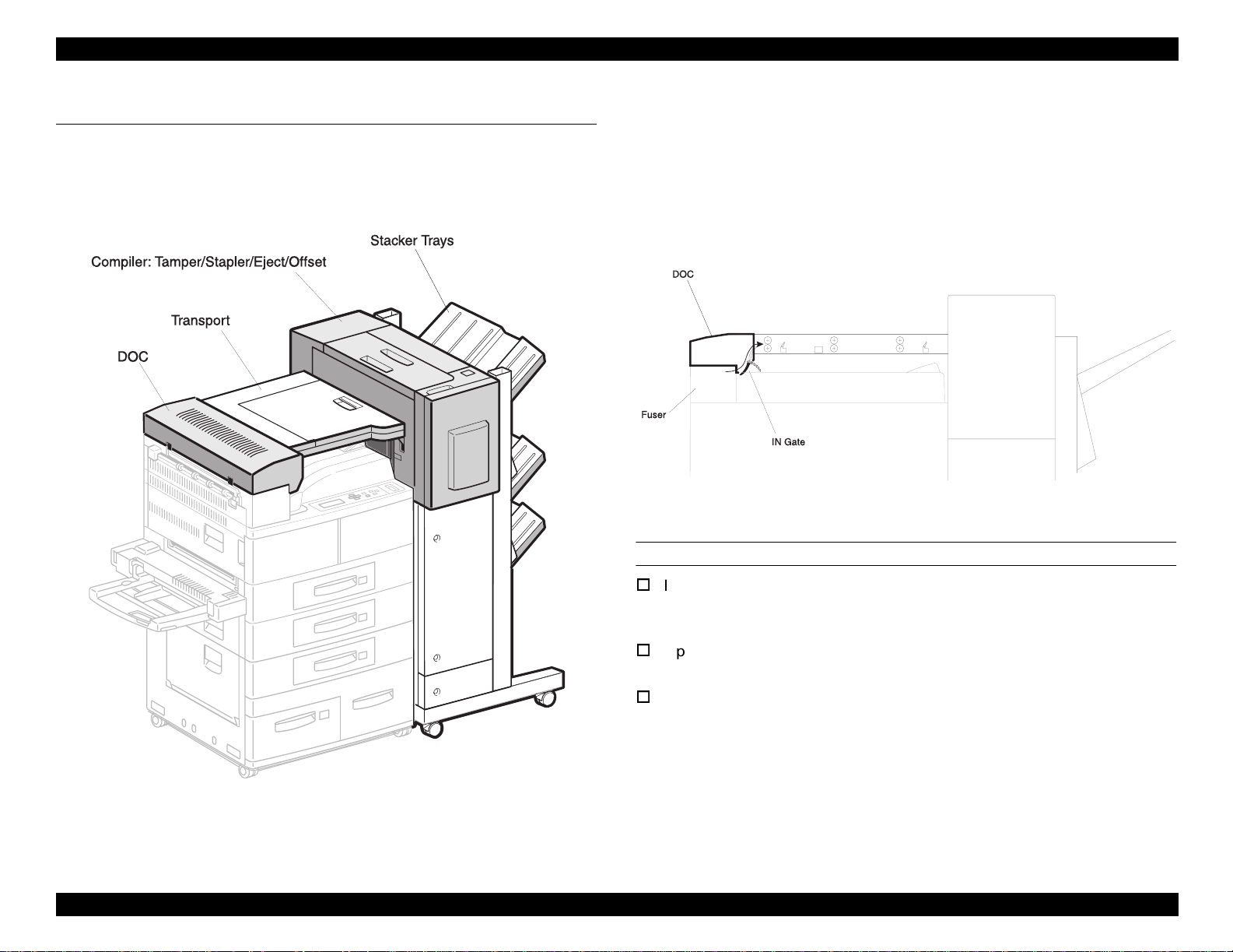
STRUCTURE
Finisher Stapler is the option of the EPSON EPL-N4000/EPL-N4000+. It is
consists of hirizontal transport unit and stack tray unit. Hirizontal transport uit
is installed to the face down output tray of the printer, and stack tray is
installed to the right side of the printer.
NOTE: Finisher Stapler cannot be used with 10 pin multipin.
FUNCTION
Stapling at the specified position.
Three ejecting paper stack trays
PAPER
Refer to product specification for EPSON EPL-N4000/EPL-N4000+.
1.1.2 Stapler Specification (TBD)
STAPLE (TBD)
Maximum amount of paper:50 sheets (paper: Xerox DP 20lb)
Staple position:Front, Rear (Corner), Rear (Straight), Multiple staple
STAPLE CARTRIDGE (TBD)
5000 staples
1.1.3 Compiler Specification (TBD)
COMPILER
Ejected paper is stacked on the Complier Tray, jogged by the tamper to the
front, and sent to the Stacker.
MAXIMUM SETTABLE AMOUNT OF PAPER
50 sheets
MINIMUM PAPER WIDTH
ELECTRIC POWER CONSUMPTION (TBD)
55W (110VAC)
210mm
1.1.4 Stacker Specification (TBD)
NOISE (TBD)
Continuous noise on the job: max. 72.8dB
SIZE AND WEIGHT
Dimensions:1,133 x 633 x 658 mm (HxWxD)
Weight:58kg
Product Description Outline 12
STACKER
Tray: 3
Page 13

EPSON EPL-N4000/EPL-N4000+ Optional Finisher Stapler Revision A
PAPAER CAPACITY
Without Staple:500 sheets/tray
With staple:Max. 30 sets or 600 sheets/tray
Real Staple Mode:15 sheets (B5 LEF, B5, B4 SEF)
Multiple Staple Mode:15 sheets (B5, SEF)
NOTE: LEF= Long Edge First, SEF= Short Edge First
1.1.5 Offset Specification (TBD)
OFFSET (TBD)
By shifting the ejecting roller, the Finisher Stapler can eject paper 15mm
offset.
Product Description Outline 13
Page 14

OPERATING PRINCIPLES
CHAPTER
2
Page 15
EPSON EPL-N4000/EPL-N4000+ Optional Finisher Stapler Revision A
2.1 Power Supply
The Power Supply of the Finisher Stapler is supplied by the 100V AC via the
printer and generated by the LVP PWB in the Finisher Stapler.
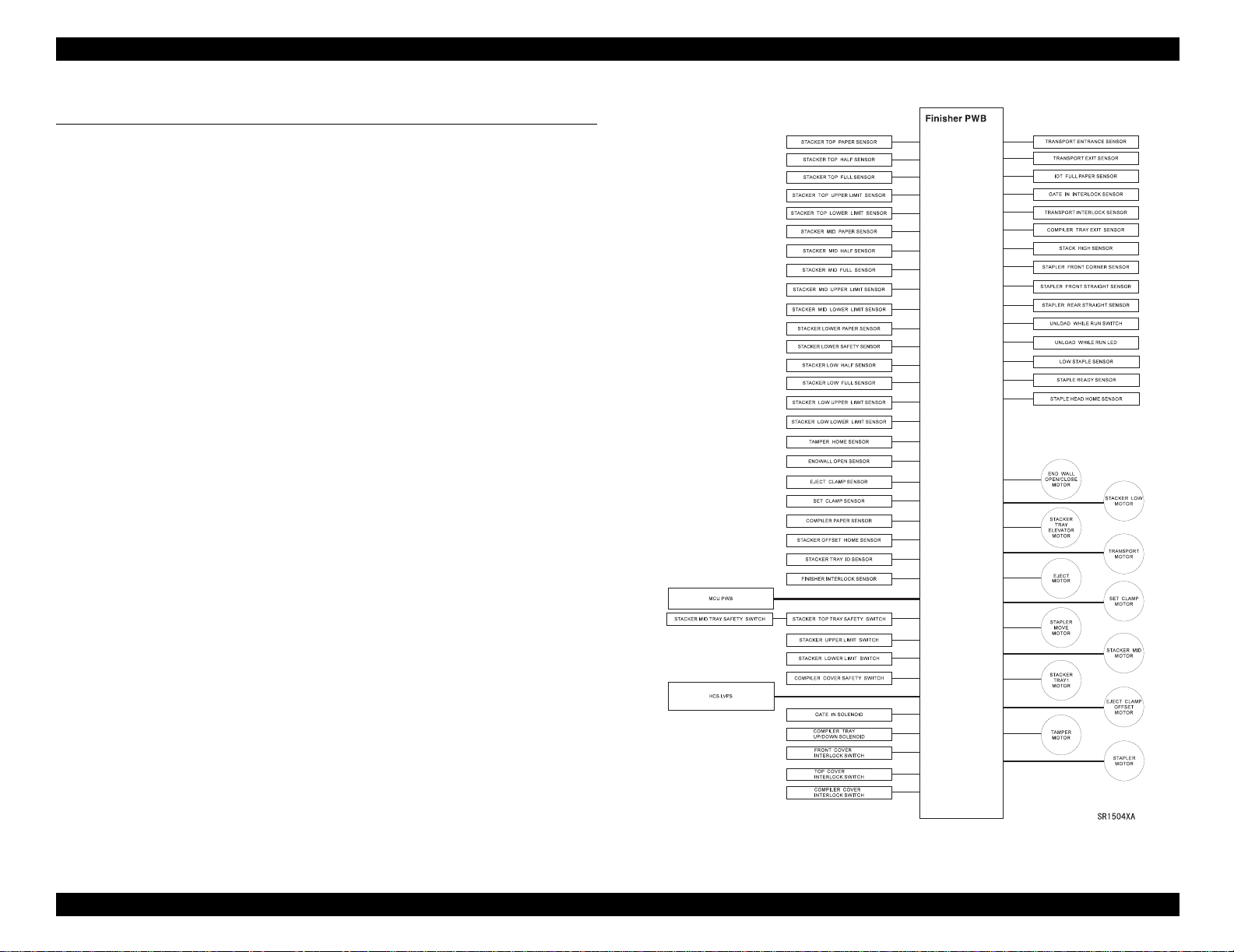
2.1.1 Control over the Finisher Stapler
LVPS sends the sensor data in the Finisher Stapler to the MCU of the printer.
Commands from the MCU of the printer is transferred to the Finisher PWB
and controls over respective components of the Finisher Stapler.
Figure 2-1. Components
Operating Principles Power Supply 15
Page 16
EPSON EPL-N4000/EPL-N4000+ Optional Finisher Stapler Revision A
2.1.2 Control Main Parts of the Finisher Stapler
Finisher PWB
LVPS PWB sends sensor data in the Finisher Stapler to MCU of the
printer. Commands from the MCU of the base engine is transferred to
the Finisher PWB and controls over respective components of the
Finisher Stapler.
HCS Low Voltage Power Supply
Generates +5VDC and +24VDC from 100VAC.
Unload While Run Switch and LED
This switch is for user to interrupt Finisher Stapler when it is
proceeding its job.
LED flashes when interruption is made.
Finisher Interlock Sensor
Supervises that the door of the Finisher Stapler is not open.
Front Cover Interlock Switch
When Front Cover is open, shut off 24VDC.
Compiler Cover Safety Switch
When Compiler Cover is open, shut off 24VDC.
IOT Full Paper Sensor
Supervises the amount of paper on the eject tray of the printer.
Transport Exit Sensor
Supervises paper passing from Transport Assembly.
Transport Interlock Sensor
Supervises the condition of the Transport Cover.
Transport Motor
Drives Transport Rolls.
2.1.2.2 Compiler
Compiler arranges paper as set.
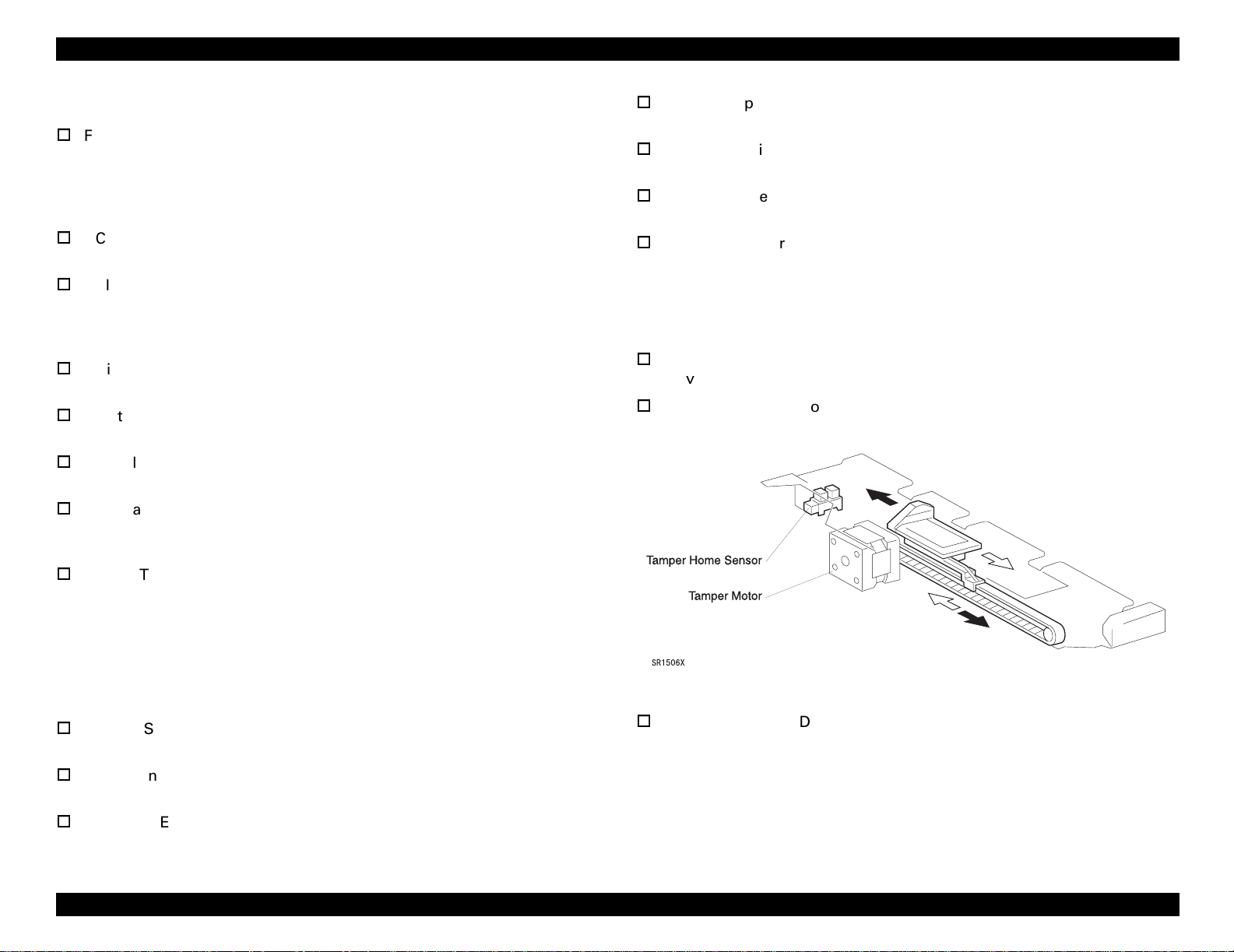
Tamper Motor
Drives Tamper which pushes paper to the end.
Tamper Home Sensor
Supervises the position of the Tamper.
Top Tray Safety Switch
Detects if there are any obstructions under the Top Tray and shut off
+24VDC and stop the Elevator Motor.
Middle Tray Safety Switch
Detects if there are any obstructions under the Middle Tray and shut
off +24VDC and stop the Elevator Motor. Top Tray Safety Switch and
Middle Tray Safety Switch are connected in series.
2.1.2.1 Transport
Shift paper from DDC to Compiler.
IN Gate Solenoid
Alternate the direction of IN Gate.
IN Gate Interlock Sensor
Supervises the position of IN Gate. (Up/Down)
Transport Entrance Sensor
Supervises paper passing to Transport Assembly.
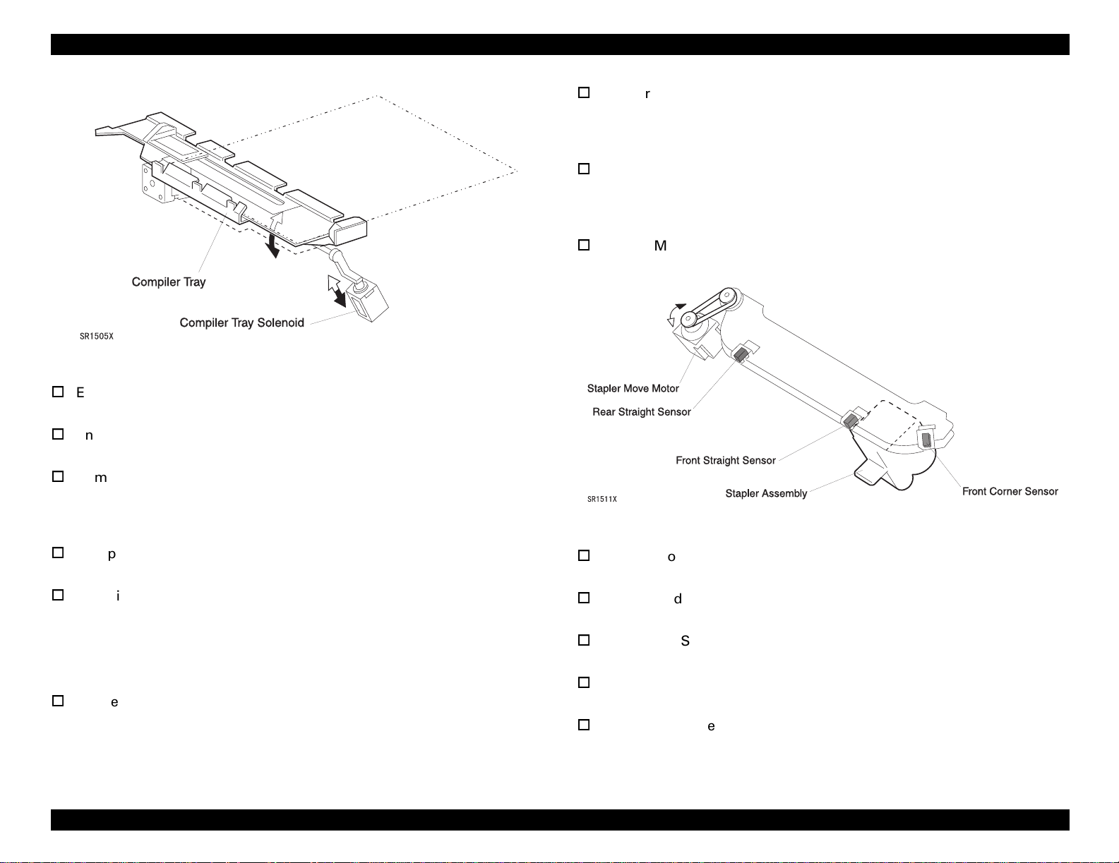
Compiler Tray Up/Down Solenoid
Slant Compiler Tray when the amount of paper has reached twenty
five.
Figure 2-2. Tamper/Tamper Home Sensor
Operating Principles Power Supply 16
Page 17
EPSON EPL-N4000/EPL-N4000+ Optional Finisher Stapler Revision A
Stapler Front Straight Sensor
Commands the position of the Stapler Unit as the Move Motor can
drive Stapler until the Stapler Unit comes to the staple position at the
front and rear edge of paper.
Stapler Rear Straight Sensor
Commands the position of the Stapler Unit as the Move Motor can
drive Stapler until the Stapler Unit comes to the staple position at the
rear corner of paper.
Stapler Move Motor
Shift the Stapler Head to the Staple position.
Figure 2-3. Compiler Tray Up / Down Solenoid
End Wall Open/Close Motor
Controls opening and closing of the End Wall.
End Wall Open Sensor
Supervises the position of the End Wall.
Compiler Tray Exit Sensor
Supervises paper ejecting through the entrance of the Compiler. HCS
uses the signal from the sensor to determine start and stop of the
Transport Motor and Eject Motor.
Compiler Paper Sensor
Supervises paper on the Compiler Tray.
Compiler Cover Interlock Switch
Supervises the position of the Compiler Cover.
2.1.2.3 Stapler
Stapler bundles paper with staple.
Stapler Front Corner Sensor
Commands the position where Stapler Unit staples at the front corner
of paper.
Stapler Motor
Drives Stapler Head during stapler stapling paper.
Staple Ready Sensor
Supervises the existence of the staple in Staple Head.
Low Staple Sensor
Supervises the remaining of the staple in Stapler.
Stapler Head Home Sensor
Supervises if the Stapler Head is at the home position.
Set Clamp Home Sensor
Supervises if the Set Clamp is at the home position.
Figure 2-4. Stapler / Sensors
Operating Principles Power Supply 17
Page 18
EPSON EPL-N4000/EPL-N4000+ Optional Finisher Stapler Revision A
Set Clamp Motor
Drives Set Clamp paddle to clamp paper on the Compiler Tray before
stapling.
Figure 2-5. Stapler
Stacker Tray Elevator Motor
Revolves Stacker Drive shaft clockwise or counterclockwise and shifts
Stacker Tray up and down.
Stacker Tray ID Sensor
Supervises the right position of the Tray.
Stacker Upper Limit Switch
Detects the upper limit of the Stacker Tray. The switch shut off the DC
power supply to the Elevator Motor.
Stacker Lower Limit Switch
Detects the lower limit of the Stacker Tray. The switch shut off the DC
power supply to the Elevator Motor.
Stacker Lower Safety Switch
Supervises the obstruction under the Bottom Tray.
Stack Height Sensor
Supervises the Tray position.
2.1.2.4 Eject and Offset
Eject and Offset carries paper compiled on the Stacker Tray and ejects offset
paper.
Eject Clamp and Offset Motor
Drives Eject Chute and Pinch Roll by shifting Eject Chute and Pinch
Roll up and down.
Eject Clamp Sensor
Supervises if Eject Roll is at the upper position or at the lower
position.
Stacker Offset Home Sensor
Supervises if Eject Roll is at the home position.
Eject Motor
Drives Eject Shaft Assembly.
2.1.2.5 Stacker Unit
Provides function to shift three Stacker Tray up and down.
2.1.2.6 Stacker Top Tray
Provides function to shift Top Stacker Tray up and down.
Stacker Tray 1 Motor
Shifts Top Tray up and down.
Stacker Top Paper Sensor
Detects if there are paper on the Top Tray.
Stacker Top Full Sensor
Detects if paper on the Top Tray is full.
Stacker Top Half Sensor
Detects if paper on the Top Tray is 50% full.
Stacker Top Upper Limit Sensor
Detects the upper limit of the Top Tray. The sensor sends signal to
Finisher Stacker PWB to shut off the DC power supply to the Stacker
Tray 1 Motor.
Stacker Top Lower Limit Sensor
Detects the lower limit of the Top Tray. The sensor sends signal to
Finisher Stacker PWB to shut off the DC power supply to the Stacker
Tray 1 Motor.
Operating Principles Power Supply 18
Page 19
EPSON EPL-N4000/EPL-N4000+ Optional Finisher Stapler Revision A
2.1.2.7 Stacker Middle Tray
Provides function to shift Middle Stacker Tray up and down.
Stacker Middle Motor
Shifts Middle Tray up and down.
Stacker Middle Paper Sensor
Detects if there are paper on Middle Tray.
Stacker Middle Full Sensor
Detects if paper on Middle Tray is full.
Stacker Middle Half Sensor
Detects if paper on Middle Tray is 50% full.
Stacker Middle Upper Limit Sensor
Detects the upper limit of Middle Tray. The sensor sends signal to
Finisher PWB to shut off the DC power supply to the Stacker Middle
Motor.
Stacker Middle Lower Limit Sensor
Detects the lower limit of Middle Tray. The sensor sends signal to
Finisher PWB to shut off the DC power supply to the Stacker Middle
Motor.
Stacker Low Lower Limit Sensor
Detects the upper limit of Bottom Tray. The sensor sends signal to
Finisher PWB to shut off the DC power supply to the Stacker Bottom
Motor.
2.1.2.8 Stacker Bottom Tray
Provides function to shift Bottom Stacker Tray up and down.
Stacker Low Motor
Shifts the Bottom Tray up and down.
Stacker Low Paper Sensor
Detects if there are paper on the Bottom Tray.
Stacker Low Full Sensor
Detects if paper on the Bottom Tray is full.
Stacker Low Half Sensor
Detects if paper on the Bottom Tray is 50% full.
Stacker Low Upper Limit Sensor
Detects the upper limit of Bottom Tray. The sensor sends signal to
Finisher PWB to shut off the DC power supply to the Stacker Bottom
Motor.
Operating Principles Power Supply 19
Page 20

EPSON EPL-N4000/EPL-N4000+ Optional Finisher Stapler Revision A
2.2 Transmission of the Driving Force
2.2.1 Transport Motor
Transport Motor is in the Compiler of the Finisher Stapler.
Figure 2-6. Transport Driving Mechanism
2.2.2 Eject Motor
Finisher PWB revolves the Eject Motor clockwise to eject paper to the Stacker
Tray. Finisher PWB also revolves the Eject Motor counterclockwise to pull
paper back to the Compiler Tray.
Figure 2-8. Eject Motor
Figure 2-7. Driving Force Transmission Outline
Operating Principles Transmission of the Driving Force 20
Page 21
EPSON EPL-N4000/EPL-N4000+ Optional Finisher Stapler Revision A
2.2.3 End Wall Motor
End Wall Motor shifts the End Wall of the Compiler Tray. When paper is sent
to the Compiler Tray, End Wall Motor shifts up the End Wall. When paper is
stapled, End Wall Motor shifts down the End Wall.
Figure 2-9. End Wall Motor
2.2.4 Tamper Motor
Tamper Motor drives the Tamper.
Figure 2-10. Tamper Motor Working Part
Figure 2-11. Tamper Motor Operational Outline
Operating Principles Transmission of the Driving Force 21
Page 22
EPSON EPL-N4000/EPL-N4000+ Optional Finisher Stapler Revision A
2.2.5 Set Clamp Motor
Figure 2-12. Set Clamp Motor Working Part
2.2.6 Offset Motor
Eject Clamp Offset Motor drives Offset Cam and Eject Clamp Cam.
SR1532X
Figure 2-14. Offset Motor Working Part
Figure 2-13. Set Clamp Motor Operational Outline
SR1531X
Figure 2-15. Offset motor Operational Outline
Operating Principles Transmission of the Driving Force 22
Page 23

EPSON EPL-N4000/EPL-N4000+ Optional Finisher Stapler Revision A
2.2.7 Stacker Elevator Motor
SR1533X
Figure 2-17. Stacker Elevator Motor Operational Outline
SR1534X
Figure 2-16. Stacker Elevator Motor Working Part
Operating Principles Transmission of the Driving Force 23
Page 24

EPSON EPL-N4000/EPL-N4000+ Optional Finisher Stapler Revision A
2.2.8 Tray Motors
SR1536XA
Figure 2-18. Tray Motor Working Part
SR1535X
Figure 2-19. Tray Motor Operational Outline
Operating Principles Transmission of the Driving Force 24
Page 25
EPSON EPL-N4000/EPL-N4000+ Optional Finisher Stapler Revision A
2.3 Paper Path
Paper goes through four main components of DOC, Transport, Compiler, and
Stacker Tray.
2.3.1 Paper Path on the Unstaple Mode
2.3.1.1 DOC
DOC is at the exit of the Fuser of the printer. DOC includes IN Gate. When
Finisher Stapler is selected, the Finisher PWB drives the IN Gate Solenoid to
alternate the direction of the IN Gate and carries paper to the HCS Transport
Assembly.
SR1503X
Figure 2-21. DOC
DOC PAPER PATH MAIN COMPONENTS
IN Gate
On normal mode, IN Gate faces up. When selected to send paper to
Staple Stacker, IN Gate Solenoid commands IN Gate to face down.
Upper Chute
Carries paper to the Transport Rolls.
IN Gate Solenoid
Controlled by Finisher PWB.
SR1502X
Figure 2-20. Main Components
Operating Principles Paper Path 25
Page 26

EPSON EPL-N4000/EPL-N4000+ Optional Finisher Stapler Revision A
2.3.1.2 Transport
Three sets of Transport Rolls send paper through Transport Assembly to
Compiler. Transport Entrance Sensor and Transport Exit Sensor supervises
paper passing.
SR1515X
Figure 2-22. Transport
TRANSPORT PAPER PATH MAIN COMPONENTS
Transport Rolls and Pinch Rolls (3 sets)
Carries paper to the Compiler.
Transport Entrance Sensor
Supervises paper entering to the Transport.
Transport Exit Sensor
Supervises paper exiting from the Transport.
IOT Full Paper Sensor
Supervises the amount of paper on the Face Down Output Tray of the
printer. When the Finisher Stapler is installed, IOT Full Paper Sensor
supervises on behalf of the printer Full Stack Sensor.
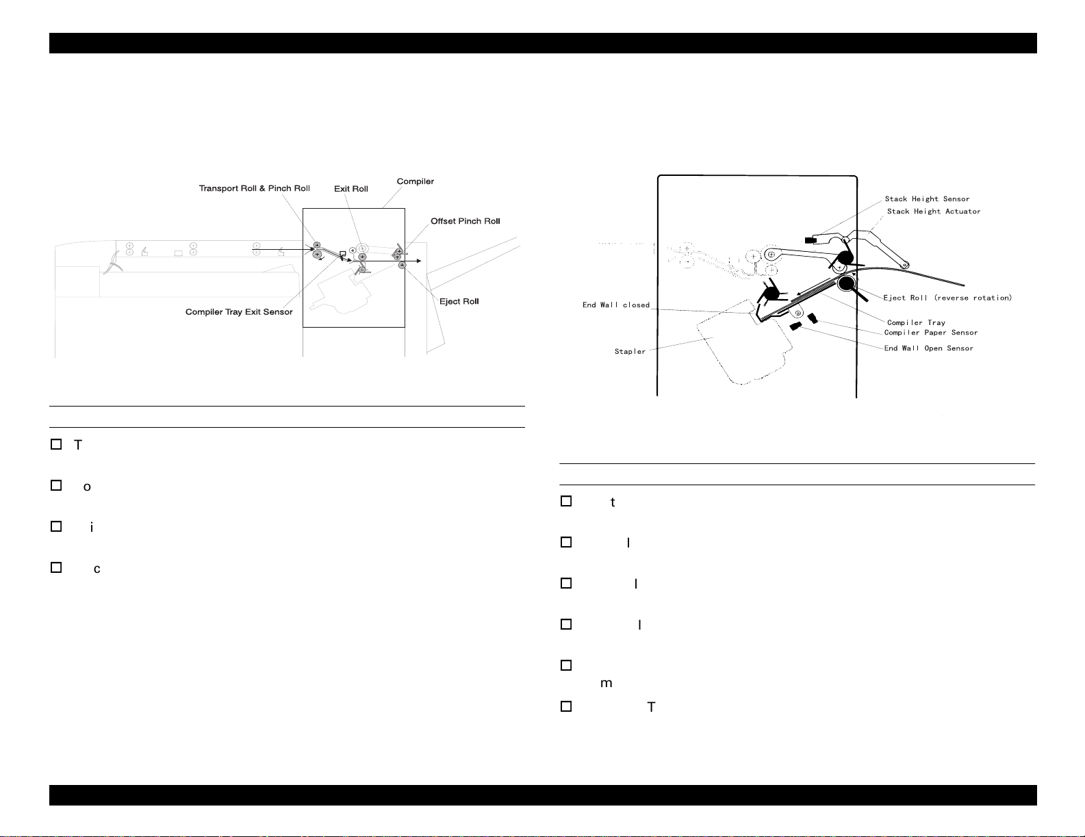
2.3.1.3 Exit/Eject
SR1518X
Figure 2-23. Exit / Eject
EXIT/EJECT PAPER PATH MAIN COMPONENTS
Transport Rolls and Pinch Rolls
Carries paper to the Compiler.
Complier Tray Exit Sensor
Supervises paper passing to the entrance of the Compiler.
Exit Roll / Paddle Assembly
Carries paper to the Offset/Eject Rolls.
Eject Roll / Paddle Assembly
Ejects paper to the Stacker Tray.
Offset Pinch Roll
Offsets and ejects paper to the Stacker Tray.
Operating Principles Paper Path 26
Page 27
EPSON EPL-N4000/EPL-N4000+ Optional Finisher Stapler Revision A
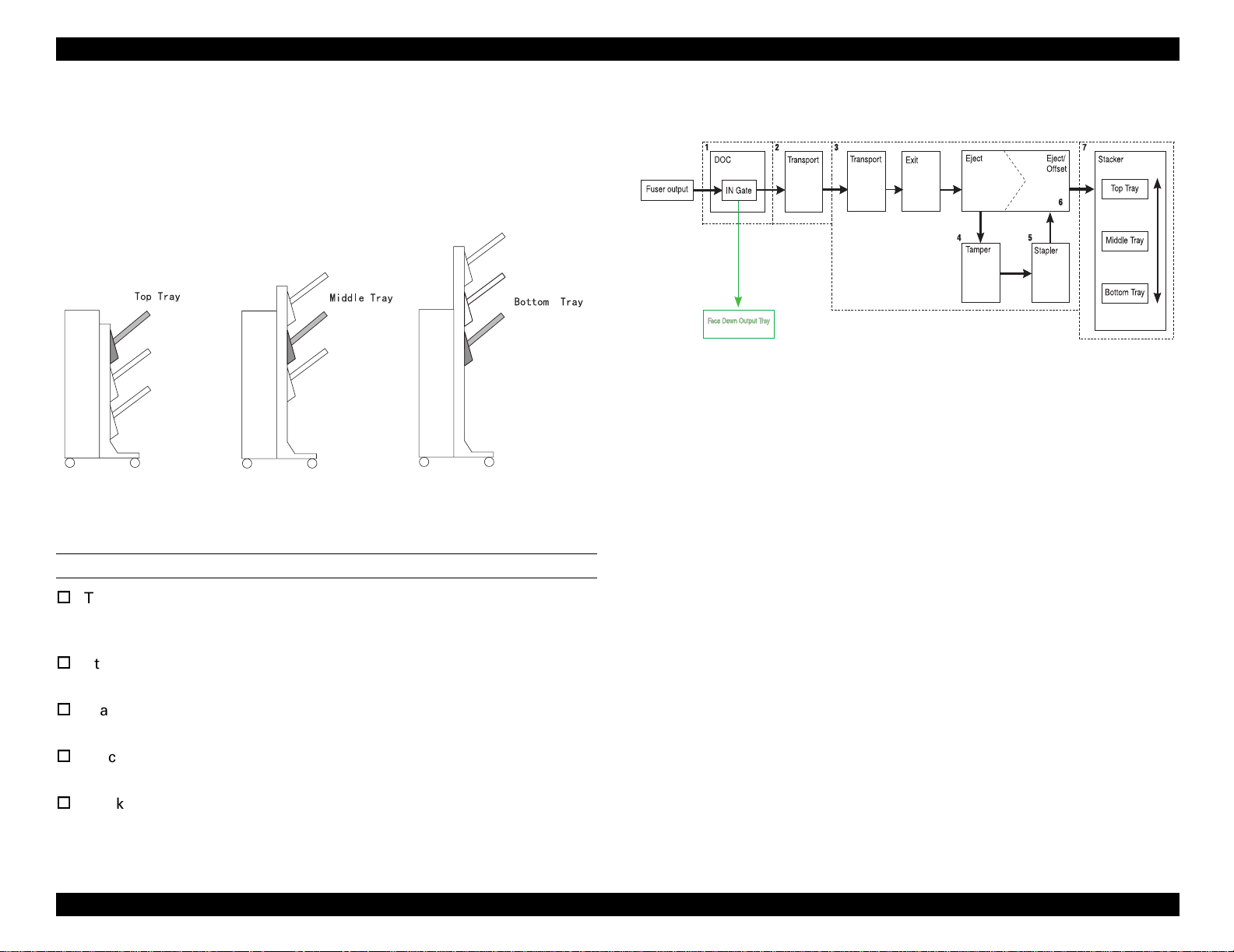
2.3.1.4 Stacker Trays
Eject Toll and Paddle Assembly ejects paper to the Stacker Tray. Stacker
Elevator shifts three Trays up and down as one of the Trays faces Eject Rolls.
ID Sensor informs the Finisher PWB that the selected Tray is at the right
position. Respective sensors supervise the amount of paper on each Tray.
SR1512X
Figure 2-24. Stacker Tray
2.3.2 Paper Path on the Staple Mode
SR1501X
Figure 2-25. Paper Path Outline
2.3.2.1 DOC
Operating principle of DOC on the staple mode is the same as on the unstaple
mode. (“DOC” on page 25)
2.3.2.2 Transport
Operating principle of Transport on the staple mode is the same as on the
unstaple mode. (“Transport” on page 26)
OFFSET PAPER PATH MAIN COMPONENTS
Top, Middle, Bottom Tray
Shifted up and down as one unit. Selected Tray stops in front of the
Eject Rolls.
Stacker Motor (Top, Middle, Bottom)
Shifts each Tray up and down.
Stacker Paper Sensor (Top, Middle, Bottom)
Supervises if there are paper on each Tray.
Stacker Full Sensor (Top, Middle, Bottom)
Supervises if paper on each Tray is 100% full.
Stacker Half Full Sensor (Top, Middle, Bottom)
Supervises if paper on each Tray is 100% full.
Operating Principles Paper Path 27
Page 28
EPSON EPL-N4000/EPL-N4000+ Optional Finisher Stapler Revision A
2.3.2.3 Exit/Eject
Paper sent from the Transport is compiled and jogged on the Compiler Tray
by specified amount. Paper is bundled by stapler at the specified corner and is
ejected to the Stacker.
SR1518X
Figure 2-26. Exit/Eject
EXIT/EJECT PAPER PATH MAIN COMPONENTS
Transport Rolls and Pinch Rolls
Carries paper to the Compiler.
Complier Tray Exit Sensor
Supervises paper entering to the Compiler.
Exit Roll / Paddle Assembly
Carries paper to the Offset/Eject Rolls.
Eject Roll / Paddle Assembly
Eject Roll counter-revolves and sends paper to the Compiler Tray.
2.3.2.4 Compiler/Tamper
Eject Roll counter-revolves and sends paper to the Compiler Tray. When
paper is sent to the Compiler Tray, End Wall Motor lifts End Wall.
SR1520X
Figure 2-27. Compiler/Tamper
COMPILER /TAMPER PAPER PATH MAIN COMPONENTS
Eject Roll
Eject Roll counter-revolves and sends paper to the Compiler Tray.
Compiler Tray
Paper is compiled and jogged on the Compiler Tray by specified amount.
End Wall
Jogs paper. Lowered when stapling.
End Wall Motor
Shifts End Wall up and down.
Tamper
Tamps paper one by one.
Compiler Tray Solenoid
When amount of paper on the Compiler Tray reaches twenty five,
Compiler Tray Solenoid shifts Compiler Tray down.
Operating Principles Paper Path 28
Page 29
EPSON EPL-N4000/EPL-N4000+ Optional Finisher Stapler Revision A
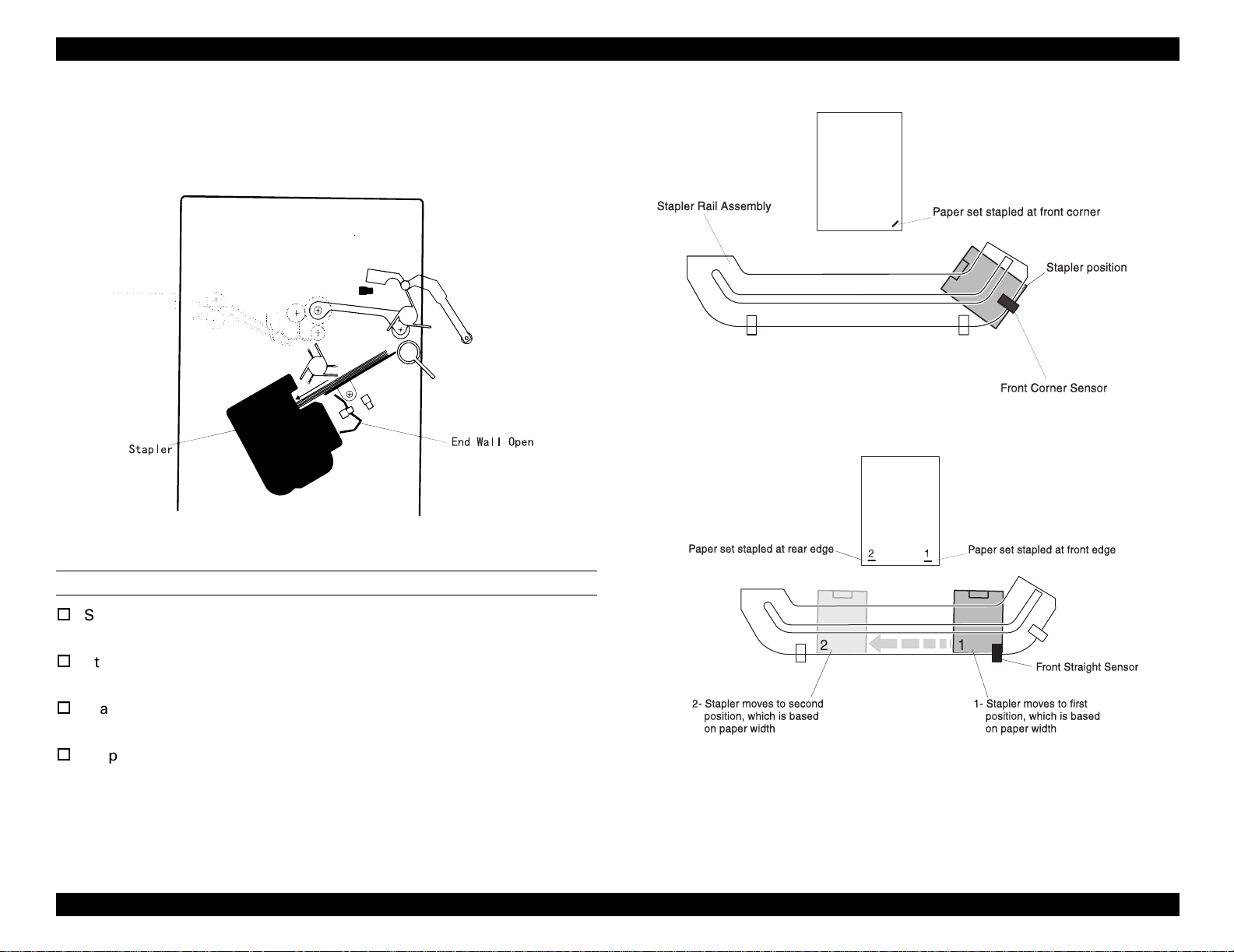
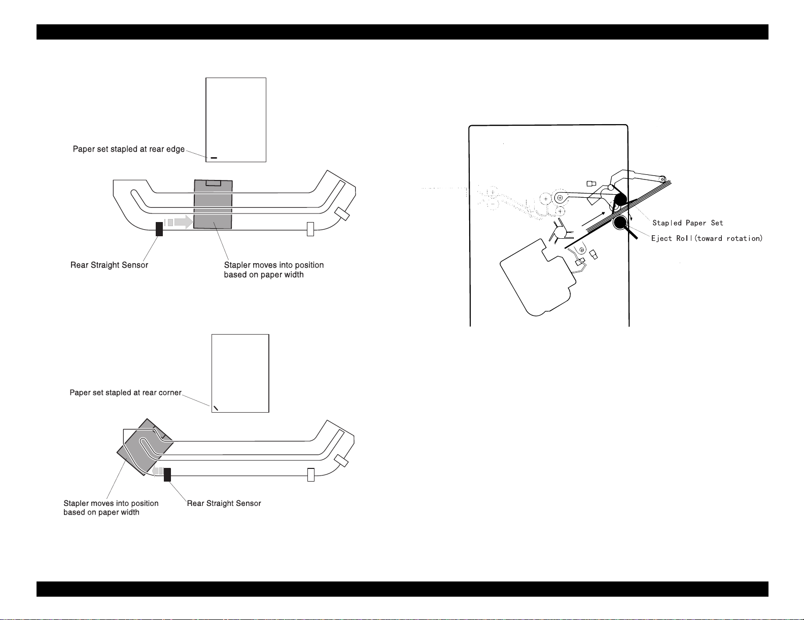
2.3.2.5 Stapler
End Wall is shifted down when stapling. Stapler Motor shifts Stapler Unit
along the rail. Sensors along rail supervises the position of the Stapler Unit.
SR1507X
Figure 2-29. Front Corner Staple
SR1522X
Figure 2-28. Stapler
STAPLER PAPER PATH MAIN COMPONENTS
Stapler Front Corner Sensor
Detects the front corner position of the Stapler Unit.
Stapler Front Straight Sensor
Detects the front straight position of the Stapler Unit.
Stapler Rear Straight Sensor
Detects the rear straight position of the Stapler Unit.
Stapler Assembly
Includes Stapler Head and Stapler Cartridge.
SR1508X
Figure 2-30. Dual (Front and Rear Edge) Staple
Operating Principles Paper Path 29
Page 30
EPSON EPL-N4000/EPL-N4000+ Optional Finisher Stapler Revision A
2.3.2.6 Eject/Offset
Eject Roll revolves counterclockwise and Eject Roll and Offset Roll eject paper
from the Compiler Tray.
SR1509X
Figure 2-31. Rear Edge Staple
SR1521X
Figure 2-33. Eject/Offset
SR1510X
Figure 2-32. Rear Corner Staple
Operating Principles Paper Path 30
Page 31

EPSON EPL-N4000/EPL-N4000+ Optional Finisher Stapler Revision A
The following figure is paper ejecting mechanism when offsetting paper.
SR1523X
Figure 2-34. Paper Eject When Offsetting Paper
2.3.2.7 Stacker Trays
Operating Principle of Stacker Tray on staple mode is the same as on the
unstaple mode. (“Stacker Trays” on page 27)
Operating Principles Paper Path 31
Page 32

DISASSEMBLY AND ASSEMBLY
CHAPTER
3
Page 33

EPSON EPL-N4000/EPL-N4000+ Optional Finisher Stapler Revision A
3.1 Outline
This chapter explains main installation and removal procedures of staple
cartridge or Finisher Stapler.
3.1.1 Preparation
Before starting removal and installation;
1. Turn off the printer.
2. Remove AC power code from the plug.
3. Wear eliminate-static wrist band to avoid damaging any electronic parts
on the print circuit board which can be easily damaged by static
electricity.
3.1.2 Attention for Handling
CAUTION
Parts name here may not match the name on the parts list
precisely. For example, MSI Tray Assembly is the same as
Tray Assembly MSI on parts list.
Use the screw with right type and right size when
installing the parts.
Wrong screws may damage threaded holes.
Do not inflict any unnecessary force for removing and
installing parts.
3.1.3 Notation for Removal and Installation
1. The position (R for right) on the removal and installation is noted,
provided that an operator faces printer Console Panel.
2. The arrows on the figure indicates the direction to move a component
when removing it.
3. Slash on the parts name indicates that several components share the
same initial word and have the same function. For example, “Gear In/
Feed/Out indicates “Gear In, Gear Feed, Gear Out”.
Disassembly and Assembly Outline 33
Page 34

EPSON EPL-N4000/EPL-N4000+ Optional Finisher Stapler Revision A
3.2 Up and Down of Finisher Stapler
When the stop button is pressed, the LED of the switch lights on and
the panel indicates “warm up”.
Finisher Stapler moves up when outputting to the bin 3. This is due to for
paper eject bin to move up.
For the safety measures, the paper eject bin can be lowered.
Finisher Stapler moves up and down under the following condition.
1. When applying the power;
When the Finisher Stapler is at bin 2 or bin 3, it moves down to bin1.
Stop button is unavailable.
No panel indication during the move.
2. When ejecting the paper to the staple Stacker;
Move to the target bin.
The panel indication during the move is the same as at the normal
printing operation.
When the EPL-N4000/EPL-N4000+ generates an error, Finisher Stapler
moves to the target position. If the printer does not start printing
again after the Finisher Stapler has moved for about one minute, the
Finisher Stapler moves down to bin 2 or bin 1 as same as in the case
of 3.
3. After ejecting paper to the Finisher Stapler;
About one minute after paper went out of compile tray, the Finisher
Stapler moves down to the bin 2. If there are no paper on bin 2 nor on
bin 3, the Finisher Stapler moves down to bin 1.
About one minute after the Finisher Stapler moves down to bin 1, or
when the stop button is pressed again, the LED of the switch lights off
and then printer will be on line again.
If the paper on bin 2 and bin 3 is removed after the Finisher Stapler
moved down to bin 2, the Finisher Stapler moves down to bin 1 after
about one minute.
No panel indication during the move.
4. When pressing the stop button of the Finisher Stapler;
The Finisher Stapler moves down to bin 1.
When the stop button is pressed during the printing procedure, bin
moves down after the job finishes or after the certain set of copies
has done.
Disassembly and Assembly Up and Down of Finisher Stapler 34
Page 35

EPSON EPL-N4000/EPL-N4000+ Optional Finisher Stapler Revision A
3.3 Installation and Removal of Finisher
Stapler and Stapler Cartridge
3.3.1 Finisher Stapler
3.3.1.1 Installation
1. Install the DOC HCS (High Capacity Stacker).
2. Lock 2 casters in the front of HCF.
3. Install the Docking Rail into the left side of the printer’s bottom.
4. Install the Docking Rail into the right side of the printer’s bottom.
5. Install the Bracket Assembly EMI.
6. Raise the Transport Assembly horizontally and raise the ShaftTransport and support the Transport Assembly.
7. Move the Finisher Stapler close to the right side of the printer.
8. Connect HCS AC power cord to the right side of the printer.
9. Push the Finisher Stapler toward to the printer, making sure that a
positioning pin goes into the positioning hole of DOC HCS.
CAUTION
10. Fix the Docking Rail with a screw.
11. Connect the HCS interface cable to the back side of the printer.
Be careful not to shut in AC power cable between the
staple Stacker and the printer.
Figure 3-1. Installing the Finisher Stapler
Disassembly and Assembly Installation and Removal of Finisher Stapler and Stapler Cartridge 35
Page 36

EPSON EPL-N4000/EPL-N4000+ Optional Finisher Stapler Revision A
ADJUSTMENT
REQUIRED
After installing the Finisher Stapler, adjust the height of the
caster (two). The adjustment procedure is as follows.
Lock nutFixed axis
Table 3-1. Height Adjustment
1. Loosen the lock nut.
2. Adjust the height by moving up and down the Finisher
Stapler with revolving the caster fixed axis.
NOTE: Be careful not to leave any gap between Finisher
Stapler and the printer body.
3. After adjustment, fix the lock nut.
Disassembly and Assembly Installation and Removal of Finisher Stapler and Stapler Cartridge 36
Page 37

EPSON EPL-N4000/EPL-N4000+ Optional Finisher Stapler Revision A
3.3.2 Removal
1. Disconnect the HCS interface cable from the printer.
2. Remove a screw from the edge of the Docking Rail.
3. Slide the Finisher Stapler away from the printer.
4. Disconnect HCS AC power cable from the printer.
5. Put the Shaft-Transport back and face down the Transport Assembly.
6. Remove Bracket Assembly EMI.
7. Remove the Docking Rail from the right side of the printer’s bottom.
8. Remove the Docking Rail from the left side of the printer’s bottom.
9. Remove DOC HCS.
Figure 3-2. Removing the Finisher Stapler
Disassembly and Assembly Installation and Removal of Finisher Stapler and Stapler Cartridge 37
Page 38

EPSON EPL-N4000/EPL-N4000+ Optional Finisher Stapler Revision A
3.3.3 Installing and Replacing Stapler Cartridge
1. Put staple into the cartridge.
2. Pull the sticker straight out to the arrow direction in the figure 2.
3. Open the Front Cover Assembly and set the cartridge with staple
inside.
4. Close the Front Cover Assembly.
Figure 3-3. Installing the Staple Cartridge
Disassembly and Assembly Installation and Removal of Finisher Stapler and Stapler Cartridge 38
Page 39

EPSON EPL-N4000/EPL-N4000+ Optional Finisher Stapler Revision A
3.3.4 Replacing the Stapler Cartridge
1. Open the Front Cover Assembly.
2. Turn the lever and take out the cartridge.
3. Take out the cartridge and remove the empty staple case.
4. Put the staple to the case.
5. Pull out the sticker straight to the arrow direction in the figure 5.
6. Open the Front Cover Assembly and set the cartridge with staple
inside.
7. Close the Front Cover Assembly.
Figure 3-4. Exchanging the Staple Cartridge
Disassembly and Assembly Installation and Removal of Finisher Stapler and Stapler Cartridge 39
Page 40

EPSON EPL-N4000/EPL-N4000+ Optional Finisher Stapler Revision A
3.4 Disassembly and Assembly
Front Cover Assembly
3.4.1 Front Cover Assembly
Refer to the exploded diagram (Figure 4-25, "HCS Covers Front" on page 166).
3.4.1.1 Removal
1. Open the Front Cover Assembly.
2. Remove E ring from the upper hinges where Front Cover Assembly and
Front Cover Inner Assembly are connected on.
3. Lift Front Cover Assembly off.
3.4.1.2 Installation
1. Install Front Cover Assembly, inserting two pairs of hinges of Front Cover
Inner Assembly into holes of Front Cover Assembly.
2. Put E ring around the upper hinges and secure Front Cover Assembly on
Front Cover Inner Assembly.
3. Close Front Cover.
Front Cover Inner Assembly
Figure 3-5. Front Cover Assembly
E ring
Disassembly and Assembly Disassembly and Assembly 40
Page 41

EPSON EPL-N4000/EPL-N4000+ Optional Finisher Stapler Revision A
3.4.2 Front Cover Inner Assembly
Refer to the exploded diagram (Figure 4-25, "HCS Covers Front" on page 166).
3.4.2.1 Removal
1. Open Top Cover.
2. Open Front Cover Assembly.
3. Remove the screw securing Front Cover Inner Assembly to HCS frame.
4. Securing Unload While Run button pressed, lift Front Cover Inner
Assembly and remove it from HCS frame.
5. Remove Front Cover Assembly. (Refer to “Front Cover Assembly” on
page 40)
3.4.2.2 Installation
1. Install Front Cover Assembly. (Refer to “Front Cover Assembly” on
page 40)
2. Install Front Cover Inner Assembly to the body by inserting two tabs at
the bottom of Front Cover Inner Assembly into cutouts in HCS frame.
3. Securing Unload While Run button pressed, insert the top part of Front
Cover Inner Assembly to HCS frame.
4. Set Front Cover Inner Assembly as Unload While Run button can move
smoothly when pressed and unpressed.
5. Secure Front Cover Inner Assembly to HCS frame with a screw.
Unload While Run button
Cutouts in HCS frame
FR
O
N
T
Front Cover Inner Assembly
6. Close the Front Cover Assembly.
7. Close Top Cover.
Figure 3-6. Front Cover Inner Assembly
Disassembly and Assembly Disassembly and Assembly 41
Page 42

EPSON EPL-N4000/EPL-N4000+ Optional Finisher Stapler Revision A
3.4.3 Front Low Cover
Refer to the exploded diagram (Figure 4-25, "HCS Covers Front" on page 166).
3.4.3.1 Removal
1. Remove HCS from the printer. (Refer to “Finisher Stapler” on page 35)
2. Remove three screws securing Front Low Cover to HCS frame.
3. Pull Front Low Cover to the right and remove it from the frame.
3.4.3.2 Installation
1. Place Front Low Cover as shown in the Figure 3-7.
2. Parallel Front Low Cover to the frame as three tabs on the frame fall into
rectangular cutouts on Front Low Cover.
3. Insert Front Low Cover to HCS frame.
4. Secure Front Low Cover to HCS frame with three screws.
5. Connect HCS and the printer. (Refer to “Finisher Stapler” on page 35)
Figure 3-7. Front Low Cover
Disassembly and Assembly Disassembly and Assembly 42
Page 43

EPSON EPL-N4000/EPL-N4000+ Optional Finisher Stapler Revision A
3.4.4 L/H Cover
Refer to the exploded diagram (Figure 4-25, "HCS Covers Front" on page 166).
3.4.4.1 Removal
1. Remove Transport Assembly. (Refer to “Transport Assembly” on
page 130)
2. Remove Rear Cover (Refer to “Rear Cover” on page 46)
3. Remove three screws securing L/H Cover to HCS frame.
4. Remove L/H Cover.
3.4.4.2 Installation
1. Install L/H Cover by first siding L/H Cover front end into the Front Cover.
2. Place L/H Cover to the frame as threaded holes of the frame and those of
L/H Cover be at the same position.
3. Secure L/H Cover to HCS frame with three screws.
4. Install Rear Cover. (Refer to “Rear Cover” on page 46)
5. Install Transport Assembly. (Refer to “Transport Assembly” on page 130)
Figure 3-8. L/H Cover
Disassembly and Assembly Disassembly and Assembly 43
Page 44

EPSON EPL-N4000/EPL-N4000+ Optional Finisher Stapler Revision A
3.4.5 L/H Cover Low
Refer to the exploded diagram (Figure 4-25, "HCS Covers Front" on page 166).
3.4.5.1 Removal
1. Remove HCS from the printer. (Refer to “Finisher Stapler” on page 35)
2. Remove Transport Assembly (Refer to “Transport Assembly” on
page 130)
3. Remove six screws securing L/H Cover Low to HCS frame.
4. Remove L/H Cover Low from the frame.
3.4.5.2 Installation
1. Place L/H Cover Low to HCS frame.
2. Secure L/H Cover Low to the HCS frame with six screws.
3. Install Transport Assembly. (Refer to “Transport Assembly” on page 130)
4. Connect HCS and the printer. (Refer to “Finisher Stapler” on page 35)
Figure 3-9. L/H Cover Low
Disassembly and Assembly Disassembly and Assembly 44
Page 45

EPSON EPL-N4000/EPL-N4000+ Optional Finisher Stapler Revision A
3.4.6 Eject Cover
Refer to the exploded diagram (Figure 4-26, "HCS Covers Rear" on page 167).
3.4.6.1 Removal
1. Remove Rear Cover. (Refer to “Rear Cover” on page 46)
2. Remove Front Cover Inner Assembly (Refer to “Front Cover Inner
Assembly” on page 41)
3. Open Top Cover.
4. Remove four screws securing Eject Cover to HCS frame.
5. Remove Eject Cover from the frame.
3.4.6.2 Installation
1. Place Eject Cover as shown in the Figure 3-10 and put Cover into HCS
frame.
2. Place Cover as four threaded holes of Cover and those of HCS frame fall
into the same position.
3. Secure Eject Cover to HCS frame with four screws.
4. Install Front Cover Inner Assembly. (Refer to “Front Cover Inner
Assembly” on page 41)
5. Install Rear Cover. (Refer to “Rear Cover” on page 46)
Figure 3-10. Eject Cover
Disassembly and Assembly Disassembly and Assembly 45
Page 46

EPSON EPL-N4000/EPL-N4000+ Optional Finisher Stapler Revision A
3.4.7 Rear Cover
Refer to the exploded diagram (Figure 4-26, "HCS Covers Rear" on page 167).
3.4.7.1 Removal
1. Open the Top Cover.
2. Remove two screws securing Rear Cover to HCS frame.
3. Lift Cover and remove it from the frame.
3.4.7.2 Installation
1. Open the Top Cover.
2. Install the Cover by hanging two tabs under the top face on two cutouts of
HCS frame.
3. Secure Rear Cover to HCS frame with two screws.
3.4.8 Harness Cover
Refer to the exploded diagram (Figure 4-26, "HCS Covers Rear" on page 167).
3.4.8.1 Removal
1. Remove three screws securing the Harness Cover to HCS frame.
2. Remove the cover.
3.4.8.2 Installation
1. Install Harness Cover as shown in the
2. Secure Harness Cover to HCS frame with three screws.
Tabs
Figure 3-11. Rear Cover
Figure 3-12. Harness Cover
Disassembly and Assembly Disassembly and Assembly 46
Page 47

EPSON EPL-N4000/EPL-N4000+ Optional Finisher Stapler Revision A
3.4.9 Add Cover
Refer to the exploded diagram (Figure 4-26, "HCS Covers Rear" on page 167).
3.4.9.1 Removal
1. Remove one screw securing the Add Cover to the HCS frame.
2. Remove the Add Cover.
3.4.9.2 Installation
1. Place the Add Cover as shown in the Figure 3-13.
2. Slide the Add Cover parallel to the frame as tabs of the HCS frame come
onto the rectangular cutouts of the Add Cover.
3. Secure the Cover to HCS frame with one screw.
Figure 3-13. Add Cover
Disassembly and Assembly Disassembly and Assembly 47
Page 48

EPSON EPL-N4000/EPL-N4000+ Optional Finisher Stapler Revision A
3.4.10 Finisher Stapler PWB Cover and Connector Cover
Refer to the exploded diagram (Figure 4-26, "HCS Covers Rear" on page 167).
3.4.10.1 Removal
1. Remove the screw securing the Connector Cover and remove it.
5. Remove the wire harness from the Bottom Harness Clamp.
6. Remove Finisher Stapler PWB Cover.
Top Harness Clamp
Bottom Harness Clamp
Harness Cover
Connector Cover
Assembly
PWB Cover
AC Power
Cable
HCS Interface
Cable
Figure 3-15. Finisher Stapler PWB Cover
Figure 3-14. Connector Cover
3.4.10.2 Installation
2. Remove Harness Cover. (Refer to “Harness Cover” on page 46)
3. Remove four screws securing PWB Cover Assembly to HCS frame and
pull out the PWB Cover from the frame.
4. Remove the wire harness from the Top Harness Clamp. (see Figure 3-15)
Disassembly and Assembly Disassembly and Assembly 48
1. Install Finisher Stapler PWB to HCS frame. (see Figure 3-15)
2. Let HCS Interface cable through the upper cutout of the Cover.
3. Let AC Power cable through the lower cutout of the Cover.
Page 49

EPSON EPL-N4000/EPL-N4000+ Optional Finisher Stapler Revision A
4. Fix the wire harness by Top Harness Clamp and Bottom Harness Clamp.
5. Install Finisher Stapler PWB Cover to the HCS frame.
6. Secure Finisher Stapler PWB Cover to the HCS frame with four screws.
7. Install Harness Cover. (Refer to “Harness Cover” on page 46)
8. Install Harness Cover to the frame by sliding as tabs on HCS frame comes
onto the rectangular cutouts of Connector Cover.
CHECK
POINT
9. Secure Harness Cover to the HCS frame with one screw.
Ensure AC Power Cable goes through the rectangular cutout of
Connector Cover.
Disassembly and Assembly Disassembly and Assembly 49
Page 50

EPSON EPL-N4000/EPL-N4000+ Optional Finisher Stapler Revision A
3.4.11 Stacker Upper Limit Switch
Refer to the exploded diagram (Figure 4-27, "RACK" on page 168).
3.4.11.1 Removal
1. Remove HCS from the printer. (Refer to “Finisher Stapler” on page 35)
2. Remove L/H Cover. (Refer to “L/H Cover” on page 43)
3. Remove four screws securing Tie Plate (Refer to Figure 4-36, "Exit" on
page 183) to the HCS frame.
NOTE: Removal of Tie Plate makes it easier to remove Upper Limit
Switch.
4. Remove two screws securing Upper Limit Switch Cover and remove the
cover.
5. Pull out J273 from Upper Limit Switch.
6. Remove two screws securing Upper Limit Switch to the HCS frame and
remove the switch.
3.4.11.2 Installation
1. Place the Stacker Upper Limit Switch as shown in the Figure 3-16 and
install the switch to the HCS frame.
2. Secure the switch to the HCS frame with two screws.
3. Connect J273 to the switch.
4. Install the Switch Cover and secure it to the HCS frame with two screws.
Tie Plate (4 screws)
Upper Limit Switch
J273
5. Install the Tie Plate to the HCS frame as the flat side of the Tie Plate faces
out.
6. Secure Tie Plate to the HCS frame with four screws.
Figure 3-16. Stacker Upper Limit Switch
7. Install L/H Cover. (Refer to “L/H Cover” on page 43)
8. Connect HCS to the printer. (Refer to “Finisher Stapler” on page 35)
Disassembly and Assembly Disassembly and Assembly 50
Page 51

EPSON EPL-N4000/EPL-N4000+ Optional Finisher Stapler Revision A
3.4.12 Stacker Lower Limit Switch
Refer to the exploded diagram (Figure 4-27, "RACK" on page 168).
3.4.12.1 Removal
1. Remove HCS from the printer. (Refer to “Finisher Stapler” on page 35)
2. Remove L/H Cover Low. (Refer to “L/H Cover Low” on page 44)
3. Pull out J274 from Lower Limit Switch.
4. Remove two screws securing Lower Limit Switch to the HCS frame and
remove the switch.
3.4.12.2 Installation
1. Place the Stacker Lower Limit Switch as shown in the Figure 3-17 and
install the switch to the HCS frame.
2. Secure the switch to the HCS frame with two screws.
3. Connect J274 to the switch.
4. Install L/H Cover Low. (Refer to “L/H Cover Low” on page 44)
5. Connect HCS to the printer. (Refer to “Finisher Stapler” on page 35)
J273
Figure 3-17. Stacker Lower Limit Switch
Disassembly and Assembly Disassembly and Assembly 51
Page 52

EPSON EPL-N4000/EPL-N4000+ Optional Finisher Stapler Revision A
3.4.13 Finisher Stapler Interlock Sensor and
Actuator
Refer to the exploded diagram (Figure 4-27, "RACK" on page 168).
3.4.13.1 Removal
1. Remove HCS from the printer. (Refer to “Finisher Stapler” on page 35)
2. Remove L/H Cover Low. (Refer to “L/H Cover Low” on page 44)
3. Release the latches, connecting Finisher Stapler Interlock Sensor to the
Docking Support, and remove the Interlock Sensor.
4. Pull out J855M from the Interlock Sensor.
5. Use the flat part of the screwdriver and remove the Actuator from the
Actuator Support.
3.4.13.2 Installation
1. Place the Actuator as shown in the Figure 3-18.
2. Insert the inside actuator pivot to the hole of the Docking Support.
3. Insert outside pivot to the arm of Actuator Support.
4. Connect J855M to the Interlock Sensor.
5. Set aside the Actuator while installing the Sensor so that the Actuator
would not obstruct installing.
6. Place the Interlock Sensor as shown in the Figure 3-18 and push the rear
latches of the Sensor into the four holes of the Docking Support.
7. Swing the Actuator and ensure it moves freely around the detecting part
of the Interlock Sensor.
8. Install L/H Cover Low. (Refer to “L/H Cover Low” on page 44)
Actuator Support
Docking Support
Actuator
J855M
Interlock Sensor
Figure 3-18. Finisher Stapler Interlock Sensor and Actuator
9. Connect HCS to the printer. (Refer to “Finisher Stapler” on page 35)
Disassembly and Assembly Disassembly and Assembly 52
Page 53

EPSON EPL-N4000/EPL-N4000+ Optional Finisher Stapler Revision A
3.4.14 Stacker Tray ID Sensor
Refer to the exploded diagram (Figure 4-27, "RACK" on page 168).
3.4.14.1 Removal
1. Remove HCS from the printer. (Refer to “Finisher Stapler” on page 35)
2. Remove Rear Cover. (Refer to “Rear Cover” on page 46)
3. Remove ID Sensor wire harness from the Harness clip.
4. Remove one screw securing Stacker Tray ID Sensor Bracket to the HCS
frame and remove the Bracket and the Sensor.
5. Pull out J837 from the Sensor.
6. Release the latches, connecting Sensor to the Bracket, and remove the
Sensor.
3.4.14.2 Installation
1. Place the Stacker Tray ID Sensor as shown in the Figure 3-19 and install
the Sensor to the Bracket.
2. Connect J837 to the Sensor.
3. Ensure the position-marking tab on the frame goes into the hole of the
Bracket and install the Sensor Bracket to the frame.
4. Secure Bracket and Sensor to the HCS frame with one screw.
5. Let ID Sensor wire harness through harness clip.
Harness clip
J837
Sensor
Sensor Bracket
6. Install Rear Cover. (Refer to “Rear Cover” on page 46)
7. Connect HCS to the printer. (Refer to “Finisher Stapler” on page 35)
Figure 3-19. Stacker Tray ID Sensor
Disassembly and Assembly Disassembly and Assembly 53
Page 54

EPSON EPL-N4000/EPL-N4000+ Optional Finisher Stapler Revision A
3.4.15 R/H Rack Cover Assembly
Refer to the exploded diagram (Figure 4-27, "RACK" on page 168).
3.4.15.1 Removal
1. Remove Bottom Tray Assembly. (Refer to “Bottom (Lower) Tray
Assembly” on page 57)
2. Remove Middle Tray Assembly. (Refer to “Middle Tray Assembly” on
page 67)
3. Remove Top Tray Assembly. (Refer to “Top Tray Assembly” on page 77)
4. Remove L/H Cover Low. (Refer to “L/H Cover Low” on page 44)
5. Remove four screws securing Elevator Hinge Bracket to Elevator Hinge
Bracket and remove Drive Bracket.
6. Remove four screws securing Elevator Hinge Bracket to R/H Rail Cover
and remove Hinge Bracket.
7. Remove six screws securing the Rail to the two grooves on the HCS
frame, lift the Rail, and remove it from the HCS frame.
8. Remove seven screws securing R/H Rack Cover to the HCS frame and pull
out the Cover from the HCS frame.
9. Pull out J273 from the Upper Limit Switch.
Elevator Drive Bracket
Elevator Hinge Bracket
R/H Rack Cover
J273
Rail
Runner
Channel
10. Pull out J274 from the Lower Limit Switch.
J274
Figure 3-20. R/H Rack Cover Assembly
Disassembly and Assembly Disassembly and Assembly 54
Page 55

EPSON EPL-N4000/EPL-N4000+ Optional Finisher Stapler Revision A
3.4.15.2 Installation
1. Place the R/H Rack Cover close to the HCS frame.
2. Connect J274 to the Lower Limit Switch.
3. Connect J273 to the Upper Limit Switch.
4. Install R/H Rack Cover to the HCS frame and secure it with seven screws.
5. Place the Rail as shown in the Figure 3-20 and slide the two Runners to
the grooves on the HCS frame.
6. Secure the Rails to the grooves with six screws.
7. Install the Elevator Hinge Bracket to the R/H Rack Cover and secure it with
four screws.
8. Install Elevator Drive Bracket to the Hinge Bracket and secure it with four
screws.
9. Install L/H Cover Low. (Refer to “L/H Cover Low” on page 44)
10. Install Top Tray Assembly. (Refer to “Top Tray Assembly” on page 77)
11. Install Middle Tray Assembly. (Refer to “Middle Tray Assembly” on
page 67)
12. Install Bottom Tray Assembly. (Refer to “Bottom (Lower) Tray Assembly”
on page 57)
Disassembly and Assembly Disassembly and Assembly 55
Page 56

EPSON EPL-N4000/EPL-N4000+ Optional Finisher Stapler Revision A
3.4.16 Stacker Elevator Motor
Refer to the exploded diagram (Figure 4-28, "Rail and Trays" on page 170).
3.4.16.1 Removal
1. Remove L/H Cover Low. (Refer to “L/H Cover Low” on page 44)
2. Remove two screws securing Motor Plate to the Motor Bracket.
3. Slide the Motor Plate to enable Motor Pulley to move freely from the
Drive Belt, and remove Motor Plate with Elevator Motor from the Bracket.
Elevator Motor
Motor Plate
4. Pull out J865.
5. Remove the E ring connecting the Motor Pulley to the Motor Shaft and
remove the pulley.
6. Remove two screws securing Elevator Motor to the Motor Plate and
remove the motor.
3.4.16.2 Installation
1. Place the Elevator Motor against Motor Plate as shown in the Figure 3-21.
2. Secure the Motor to the Plate with two screws.
3. Insert the Motor Pulley into the Motor shaft.
4. Install Pulley to the Motor shaft with E ring.
5. Install Elevator Motor with Motor Plate to the hole of Motor Bracket and
hang the Drive Belt around the Motor Pulley.
6. Secure the Motor Plate to the Motor Bracket with two screws.
7. Connect J865.
8. Install L/H Cover Low. (Refer to “L/H Cover Low” on page 44)
J865
Motor Pulley
Motor Bracket
Motor Pulley
Drive Belt
Figure 3-21. Stacker Elevator Motor
Disassembly and Assembly Disassembly and Assembly 56
Page 57

EPSON EPL-N4000/EPL-N4000+ Optional Finisher Stapler Revision A
3.4.17 Bottom (Lower) Tray Assembly
Refer to the exploded diagram (Figure 4-29, "Lower Tray" on page 172).
3.4.17.1 Removal
1. Remove HCS from the printer. (Refer to “Finisher Stapler” on page 35)
2. Remove Harness Cover. (Refer to “Harness Cover” on page 46)
3. Remove Harness Guide Cover at the bottom.
4. Release wires inside the Harness Guide from the clip.
5. Pull out J830A, J871A, J874A, and J875A.
6. Remove a screw securing Harness Guide and remove Harness Guide.
7. Remove two screws at the bottom of the Bottom Tray Assembly,
Securing the Assembly to the HCS frame.
8. Loosen two screws at the top of the Bottom Tray Assembly, Securing the
Assembly to the HCS frame.
9. Lift the Bottom Tray Assembly off the screws and remove the Assembly
from the HCS frame.
3.4.17.2 Installation
9. Connect HCS to the printer. (Refer to “Finisher Stapler” on page 35)
Loosen Only
J874A
J871
J875A
J830A
1. Hang the Bottom Tray Assembly on the HCS frame as the two screws on
the top of the HCS frame go under the screw holes of the Top Tray
Assembly.
2. Fasten two screws.
3. Secure the bottom of the Assembly to the HCS frame with two screws.
4. Let the Bottom Tray Assembly wire harness through the slot at the
bottom of the Harness Guide.
5. Install the Bottom Harness Guide and secure it to the HCS frame with a
screw.
6. Connect J830A, J871A, J874A, and J875A.
7. Secure the wires under the clip.
8. Install Harness Cover. (Refer to “Harness Cover” on page 46)
Figure 3-22. Bottom (Lower) Tray Assembly
Harness Guide
Harness Guide Cover
Disassembly and Assembly Disassembly and Assembly 57
Page 58

EPSON EPL-N4000/EPL-N4000+ Optional Finisher Stapler Revision A
3.4.18 Bottom Tray Front Cover
Refer to the exploded diagram (Figure 4-29, "Lower Tray" on page 172).
3.4.18.1 Removal
1. Remove Bottom Tray Assembly. (Refer to “Bottom (Lower) Tray
Assembly” on page 57)
2. Break open Bottom Tray Front Cover and remove the Cover.
3.4.18.2 Installation
1. Install the Front Cover to the Bottom Tray.
2. Install Bottom Tray Assembly. (Refer to “Bottom (Lower) Tray Assembly”
on page 57)
Bottom Tray
Front Cover
Figure 3-23. Finisher Stapler Interlock Sensor and Actuator
Disassembly and Assembly Disassembly and Assembly 58
Page 59

EPSON EPL-N4000/EPL-N4000+ Optional Finisher Stapler Revision A
3.4.19 Bottom Tray Half and Full Sensors
Refer to the exploded diagram (Figure 4-29, "Lower Tray" on page 172).
3.4.19.1 Removal
1. Remove the Bottom Tray Assembly. (Refer to “Bottom (Lower) Tray
Assembly” on page 57)
2. Slide off the Rear Harness Cover from the Bottom Tray Rear.
3. Remove the screw at the bottom of the Bottom Tray Rear Cover, securing
the rear cover to the Tray frame.
4. Set the latches at the upper part of the Rear Cover off and remove the
Cover.
5. Remove the screw securing Sensor Bracket to the Tray frame and remove
the Bracket.
6. Pull out P860 from the Half Sensor.
7. Push the Sensor latches in and release, which connects the Sensor to the
Bracket, and remove the Sensor.
8. Pull out P861 from Full Sensor.
9. Push the Sensor latches in and release, which connects the Sensor to the
Bracket, and remove the Sensor.
6. First set the latches at the upper part of Rear Cover and then secure it to
the Tray frame with a screw.
7. Let the wire harness through the cutout at the back of the Cover and slide
the Rear Harness Cover into the Bottom Tray Rear Cover.
8. Install Bottom Tray Assembly. (Refer to “Bottom (Lower) Tray Assembly”
on page 57)
Sensor Bracket
Full Sensor
Bottom Tray
Rear Cover
Half Sensor
J860
J861
3.4.19.2 Installation
1. Place the Full Sensor as shown in the Figure 3-24 and insert it with latches
ahead into the cutouts of the Sensor Bracket and set the latches on.
2. Connect P861 to the Full Sensor.
3. Place the Half Sensor as shown in the Figure 3-24 and insert Half Sensor
with latches ahead to the cutouts of the Sensor Bracket and set the
latches on.
4. Connect P860 to Full Sensor.
5. Install Sensor Bracket to the Tray frame and secure it to the frame with a
screw.
Disassembly and Assembly Disassembly and Assembly 59
Rear Harness Cover
Figure 3-24. Bottom Tray Half and Full Sensors
Page 60

EPSON EPL-N4000/EPL-N4000+ Optional Finisher Stapler Revision A
3.4.20 Bottom Tray Lower and Upper Limit Sensor
3.4.20.1 Removal
1. Remove the Bottom Tray Assembly. (Refer to “Bottom (Lower) Tray
Assembly” on page 57)
2. Slide off Rear Harness Cover from Bottom Tray Rear Cover.
3. Remove the screw on the bottom of the Rear Cover securing Bottom Tray
Rear Cover to the Tray frame.
4. Release the latches at the upper part of the Rear Cover and remove the
Cover.
5. Remove screws securing Sensor Bracket to the Tray frame and remove
the Sensor Bracket.
6. Pull out P850 from the Upper Limit Sensor.
7. Push the Sensor latches in and release, which connects the Sensor to the
Bracket, and remove the Sensor.
8. Pull out P851 from Lower Limit Sensor.
9. Push the Sensor latches in and release, which connects the Sensor to the
Bracket, and remove the Sensor.
3.4.20.2 Installation
7. Let the wire harness through the cutout at the back of the Cover and slide
the Rear Harness Cover into the Bottom Tray Rear Cover.
8. Install Bottom Tray Assembly. (Refer to “Bottom (Lower) Tray Assembly”
on page 57)
P850
Sensor Bracket
P851
Lower Limit Sensor
Upper Limit Sensor
1. Place the Lower Limit Sensor as shown in the Figure 3-25 and insert it
with latches ahead into the cutouts of the Sensor Bracket and set the
latches on.
2. Connect P851 to the Full Sensor.
3. Place the Upper Limit Sensor as shown in the Figure 3-24 and insert it
with latches ahead into the cutouts of the Sensor Bracket and set the
latches on.
4. Connect P850 to Full Sensor.
5. Install Sensor Bracket to the Tray frame and secure it to the frame with a
screw.
6. First set the latches at the upper part of Rear Cover and then secure it to
the Tray frame with a screw.
Figure 3-25. Bottom Tray Lower and Upper Limit Sensor
Disassembly and Assembly Disassembly and Assembly 60
Page 61

EPSON EPL-N4000/EPL-N4000+ Optional Finisher Stapler Revision A
3.4.21 Bottom Tray
Refer to the exploded diagram (Figure 4-29, "Lower Tray" on page 172).
3.4.21.1 Removal
1. Remove Bottom Tray Assembly. (Refer to “Bottom (Lower) Tray
Assembly” on page 57)
2. Remove Bottom Tray Drive Belts. (Refer to “Bottom Tray Drive Belts” on
page 65)
3. Remove Bottom Tray Paper Sensor. (Refer to “Bottom Tray Paper
Sensor” on page 62)
4. Remove Bottom Tray Safety Sensor. (Refer to “Bottom Tray Safety
Sensor” on page 63)
5. Remove screw securing Sensor wire harness to the bottom of the Tray
and remove the harness.
6. Remove the Tray by sliding it off from the grooves of the Front Tray frame
and the Rear Tray frame. (Figure 1)
7. Remove four screws securing the Carriage to the Tray and remove the
Tray. (Figure 2)
3.4.21.2 Installation
7. Install Bottom Tray Assembly. (Refer to “Bottom (Lower) Tray Assembly”
on page 57)
Frame
Frame
1. Install the Carriage to the Tray and secure it with four screws.
2. Install the Tray into the grooves of Front Tray Frame and Rear Tray
Frame.
3. Install Sensor wire harness to the bottom of the Tray and secure it with
screw.
4. Install Bottom Tray Safety Sensor. (Refer to “Bottom Tray Safety Sensor”
on page 63)
5. Install Bottom Tray Paper Sensor. (Refer to “Bottom Tray Paper Sensor”
on page 62)
6. Install Bottom Tray Drive Belts. (Refer to “Bottom Tray Drive Belts” on
page 65) to the both sides of the frame.
Carriage
Tray
Figure 3-26. Bottom Tray
Disassembly and Assembly Disassembly and Assembly 61
Page 62

EPSON EPL-N4000/EPL-N4000+ Optional Finisher Stapler Revision A
3.4.22 Bottom Tray Paper Sensor
Refer to the exploded diagram (Figure 4-29, "Lower Tray" on page 172).
3.4.22.1 Removal
1. Remove Bottom Tray Assembly. (Refer to “Bottom (Lower) Tray
Assembly” on page 57)
2. Remove three screws securing Back Cover to the Tray and remove the
Cover.
3. Remove a screw securing Paper Sensor Bracket to the Tray and remove
the Sensor Bracket along with Paper Sensor.
4. Pull out J859 from the Sensor.
5. Push the Sensor latcheses in and release, which connects the sensor to
the bracket, and remove the sensor.
3.4.22.2 Installation
1. Place the Bottom Tray Paper Sensor as shown in the Figure 3-27 and
insert it with the latches ahead into the cutouts of the Sensor Bracket and
set the latches on.
2. Connect J859 to the Sensor.
3. Ensure position-marking tabs on the Tray comes into the holes of the
Bracket and install the Sensor Bracket to the Tray.
4. Secure the Bracket to the Tray with a screw.
Sensor Bracket
Paper Sensor
J859
Back Cover
Figure 3-27. Bottom Tray Paper Sensor
5. Install the Back Cover to the Tray and secure it with three screws.
6. Install Bottom Tray Assembly. (Refer to “Bottom (Lower) Tray Assembly”
on page 57)
Disassembly and Assembly Disassembly and Assembly 62
Page 63

EPSON EPL-N4000/EPL-N4000+ Optional Finisher Stapler Revision A
3.4.23 Bottom Tray Safety Sensor
Refer to the exploded diagram (Figure 4-29, "Lower Tray" on page 172).
3.4.23.1 Removal
1. Remove the Bottom Tray Assembly. (Refer to “Bottom (Lower) Tray
Assembly” on page 57)
2. Remove three screws securing the Back Cover to the Tray and remove the
Cover.
3. Remove the screw securing the Safety Sensor Bracket to the Tray and
remove the Bracket along with the Safety Sensor.
4. Pull out the J831 from the Sensor.
5. Push in the Sensor lathes in and release, which connects the Sensor to
the Bracket, and remove the Sensor.
3.4.23.2 Installation
1. Place the Bottom Tray Safety Sensor as shown in the Figure 3-28 and
insert it with the latcheses ahead into the cutouts of the Sensor Bracket
and set the latches on.
2. Connect J831 to the Sensor.
3. Ensure position-marking tabs on the Tray comes into the holes of the
Bracket and install the Sensor Bracket to the Tray.
Sensor Bracket
J859
Safety Sensor
Back Cover
Figure 3-28. Bottom Tray
4. Secure the Bracket to the Tray with a screw.
5. Install the Back Cover to the Tray and secure it with three screws.
6. Install Bottom Tray Assembly. (Refer to “Bottom (Lower) Tray Assembly”
on page 57)
Disassembly and Assembly Disassembly and Assembly 63
Page 64

EPSON EPL-N4000/EPL-N4000+ Optional Finisher Stapler Revision A
3.4.24 Bottom Tray Motor
Refer to the exploded diagram (Figure 4-29, "Lower Tray" on page 172).
3.4.24.1 Removal
1. Remove the Bottom Tray Assembly. (Refer to “Bottom (Lower) Tray
Assembly” on page 57)
2. Remove Rear Harness Cover from the Bottom Tray Rear Cover by sliding
it off.
3. Remove the screw at the bottom of the Rear Cover securing Bottom Tray
Rear Cover to the Tray Frame.
4. Release the latches at the upper part of the Rear Cover and remove the
Cover.
5. Remove four screws securing the Motor Bracket to the Tray and remove
the Bracket along with the Motor.
6. Remove the E ring binding Gear to the Motor shaft and remove the Shaft
Gear.
7. Remove two screws securing the Motor to the Bracket and remove the
Motor.
3.4.24.2 Installation
1. Install the Motor to the Motor Bracket and secure it with two screws.
2. Install the Gear to the end of Motor Shaft.
3. Secure the Gear to the Shaft with E ring.
4. Install the Bracket along with the Motor to the Tray frame and secure it
with four screws.
5. Set the latches on the top of the Rear Cover and then secure it to the Tray
frame with a screw.
Shaft Gear
Motor Bracket
Tray Motor
J871
Figure 3-29. Bottom Tray Motor
6. Let the wire harness though the cutouts on the back of the Cover and
install Rear Harness Cover by sliding.
7. Install Bottom Tray Assembly. (Refer to “Bottom (Lower) Tray Assembly”
on page 57)
Disassembly and Assembly Disassembly and Assembly 64
Page 65

EPSON EPL-N4000/EPL-N4000+ Optional Finisher Stapler Revision A
3.4.25 Bottom Tray Drive Belts
Refer to the exploded diagram (Figure 4-30, "Lower Tray Frame" on page 173).
3.4.25.1 Removal
1. Remove the Bottom Tray Assembly. (Refer to “Bottom (Lower) Tray
Assembly” on page 57)
2. Remove the Bottom Tray Front Cover. (Refer to “Bottom Tray Front
Cover” on page 58)
3. Remove the Tension Spring from the Tension Plate. (Figure 3-30)
4. Remove two screws securing Tension Plate to the Tray frame and remove
the Plate.
5. Remove two screws securing Belt Clamp to the Tray and remove the
Clamp.
6. Remove the Belt from the Clamp by sliding.
7. Remove the E ring binding the Drive Gear to the Shaft and remove the
Gear.
8. Remove the Front Drive Gear.
Front Belt
Tension Spring
9. Remove the Bottom Tray Motor. (Refer to “Bottom Tray Motor” on
page 64)
10. Remove the screw securing the Sensor Bracket to the Tray frame and
remove the Bracket.
11. Remove the Tension Spring from the Tension Plate. (Figure 3-31)
12. Remove two screws securing the Limit Actuator to the Tray frame and
remove the Actuator.
13. Remove two screws securing the Tension Plate to the Tray frame and
remove the Tension Plate.
14. Remove two screws securing the Belt Clamp to the Tray frame and
remove the Belt Clamp.
15. Remove the Belt from the Clamp by sliding.
16. Remove the E ring binding the Drive Gear to the shaft and remove the
Drive Gear.
17. Remove the Rear Drive Belt.
Pulley
Tension Plate
Belt Clamp
Belt
Tension Spring
Figure 3-30. Front Drive Belt
Disassembly and Assembly Disassembly and Assembly 65
Page 66

EPSON EPL-N4000/EPL-N4000+ Optional Finisher Stapler Revision A
Rear Belt
Pulley
Belt
Drive Gear
Belt Clamp
Limit
Actuator
Tension Spring
Figure 3-31. Rear Drive Belt
9. Install the Bottom Tray Motor. (Refer to “Bottom Tray Motor” on page 64)
10. Install the Front Drive Belt as shown in the Figure 3-30.
11. Install the Rear Belt to the Clamp by sliding.
12. Secure the Clamp to the Tray frame with two screws.
13. Install the Tension Plate to the frame and secure it with two screws.
14. Hang the Tension Spring to the Tension Plate.
15. Install the Bottom Tray Front Cover. (Refer to “Bottom Tray Front Cover”
on page 58)
16. Install Bottom Tray Assembly. (Refer to “Bottom (Lower) Tray Assembly”
on page 57)
Tension Spring
Tension Plate
3.4.25.2 Installation
1. Install the Rear Drive Belt as shown in the Figure 3-31.
2. Install the Drive Gear to the shaft and secure it with E ring.
3. Slide the Rear Belt around the Clamp.
4. Secure the Clamp to the Tray frame with two screws.
5. Install the Tension Plate to the frame and secure it with two screws.
6. Install the Limit Actuator to the frame and secure it with two screws.
7. Hang the Tension Spring on the Tension Plate.
8. Install the Sensor Bracket to the Tray frame and secure it with a screw.
Disassembly and Assembly Disassembly and Assembly 66
Page 67

EPSON EPL-N4000/EPL-N4000+ Optional Finisher Stapler Revision A
3.4.26 Middle Tray Assembly
Refer to the exploded diagram (Figure 4-31, "Middle Tray" on page 175).
3.4.26.1 Removal
1. Remove the HCS from the printer. (Refer to “Finisher Stapler” on
page 35)
2. Remove the Harness Cover. (Refer to “Harness Cover” on page 46)
3. Remove the bottom Harness Guide Cover.
4. Release wires under the Harness Guide from the clip.
5. Pull out J887A, J870, J872A, and J873A.
6. Remove the screw securing bottom Harness Guide and remove the
Bottom Harness Guide.
7. Remove the top Harness Guide Cover.
8. Remove the screw holing top Harness Guide and remove the top Harness
Guide.
9. Remove two screws on the bottom of the Middle Tray Assembly securing
the Assembly to the HCS frame.
10. Loosen two screws on the top of the Middle Tray Assembly securing the
Assembly to the HCS frame.
6. Install the top Harness Guide Cove.
7. Install the bottom Harness Guide and secure it to the HCS frame with a
screw.
8. Connect J877A, J870, J872A, and J873A.
9. Secure wires under the clip.
10. Install the bottom Harness Guide Cover.
11. Install the Harness Cover. (Refer to “Harness Cover” on page 46)
12. Install Bottom Tray Assembly. (Refer to “Bottom (Lower) Tray Assembly”
on page 57)
Middle Tray
Assembly
J871
J874A
J875A
J830A
Loosen Only
11. Lift the Middle Tray Assembly out of two screw holes and remove the
Assembly from the HCS frame.
Harness Guide
Cover
3.4.26.2 Installation
1. Hang the Middle Tray Assembly on two screws on the top of HCS frame.
2. Fasten the screws.
3. Secure the bottom of the Assembly to the HCS frame with two screws.
4. Let the Middle Tray Assembly wire harness through the slot on the
bottom of the Harness Guide.
5. Install the Top Harness Guide and secure it to the HCS frame with a
screw.
Disassembly and Assembly Disassembly and Assembly 67
Top Harness Guide
Bottom Harness Guide
Figure 3-32. Middle Tray Assembly
Harness Guide
Cover
Page 68

EPSON EPL-N4000/EPL-N4000+ Optional Finisher Stapler Revision A
3.4.27 Middle Tray Front Cover
Refer to the exploded diagram (Figure 4-31, "Middle Tray" on page 175).
3.4.27.1 Removal
1. Remove the Middle Tray Assembly. (Refer to “Middle Tray Assembly” on
page 67)
2. Break open the Middle Tray Front Cover and remove the cover.
3.4.27.2 Installation
1. Install the Front Cover to the Middle Tray.
2. Install Middle Tray Assembly. (Refer to “Middle Tray Assembly” on
page 67)
Figure 3-33. Middle Tray Front Cover
Disassembly and Assembly Disassembly and Assembly 68
Page 69

EPSON EPL-N4000/EPL-N4000+ Optional Finisher Stapler Revision A
3.4.28 Middle Tray Half and Full Sensors
Refer to the exploded diagram (Figure 4-31, "Middle Tray" on page 175).
3.4.28.1 Removal
1. Remove the Middle Tray Assembly. (Refer to “Middle Tray Assembly” on
page 67)
2. Slide off the Rear Harness Cover from the Middle Tray Rear.
3. Remove the screw at the bottom of the Middle Tray Rear Cover, securing
the rear cover to the Tray frame.
4. Set the latches at the upper part of the Rear Cover off and remove the
Cover.
5. Remove the screw securing Sensor Bracket to the Tray frame and remove
the Bracket.
6. Pull out P857 from the Half Sensor.
7. Push the Sensor latches in and release, which connects the Sensor to the
Bracket, and remove the Sensor.
8. Pull out P858 from Full Sensor.
9. Push the Sensor latches in and release, which connects the Sensor to the
Bracket, and remove the Sensor.
6. First set the latches at the upper part of Rear Cover and then secure it to
the Tray frame with a screw.
7. Let the wire harness through the cutout at the back of the Cover and slide
the Rear Harness Cover into the Bottom Tray Rear Cover.
8. Install Middle Tray Assembly. (Refer to “Middle Tray Assembly” on
page 67)
Sensor Bracket
Full Sensor
Bottom Tray
Rear Cover
J861
Half Sensor
J860
3.4.28.2 Installation
1. Place the Full Sensor as shown in the Figure 3-34 and insert it with latches
ahead into the cutouts of the Sensor Bracket and set the latches on.
2. Connect P858 to the Full Sensor.
3. Place the Half Sensor as shown in the Figure 3-34 and insert Half Sensor
with latches ahead to the cutouts of the Sensor Bracket and set the
latches on.
4. Connect P857 to Full Sensor.
5. Install Sensor Bracket to the Tray frame and secure it to the frame with a
screw.
Disassembly and Assembly Disassembly and Assembly 69
Rear Harness Cover
Figure 3-34. Middle Tray Half and Full Sensors
Page 70

EPSON EPL-N4000/EPL-N4000+ Optional Finisher Stapler Revision A
3.4.29 Middle Tray Lower and Upper Limit Sensor
Refer to the exploded diagram (Figure 4-31, "Middle Tray" on page 175).
3.4.29.1 Removal
1. Remove the Top Tray Assembly. (Refer to “Middle Tray Assembly” on
page 67)
2. Slide off Rear Harness Cover from Middle Tray Rear Cover.
3. Remove the screw on the bottom of the Rear Cover securing Top Tray
Rear Cover to the Tray frame.
4. Release the latches at the upper part of the Rear Cover and remove the
Cover.
5. Remove screws securing Sensor Bracket to the Tray frame and remove
the Sensor Bracket.
6. Pull out P848 from the Upper Limit Sensor.
7. Push the Sensor latches in and release, which connects the Sensor to the
Bracket, and remove the Sensor.
8. Pull out P849 from Lower Limit Sensor.
9. Push the Sensor latches in and release, which connects the Sensor to the
Bracket, and remove the Sensor.
6. First set the latches at the upper part of Rear Cover and then secure it to
the Tray frame with a screw.
7. Let the wire harness through the cutout at the back of the Cover and slide
the Rear Harness Cover into the Bottom Tray Rear Cover.
8. Install Middle Tray Assembly. (Refer to “Middle Tray Assembly” on
page 67)
P848
Sensor Bracket
Upper Limit Sensor
3.4.29.2 Installation
1. Place the Lower Limit Sensor as shown in the Figure 3-35 and insert it
with latcheses ahead into the cutouts of the Sensor Bracket and set the
latches on.
2. Connect P849 to the Lower Limit Sensor.
3. Place the Upper Limit Sensor as shown in the Figure 3-35 and insert it
with latches ahead into the cutouts of the Sensor Bracket and set the
latches on.
4. Connect P848 to Upper Limit Sensor.
5. Install Sensor Bracket to the Tray frame and secure it to the frame with a
screw.
P849
Lower Limit Sensor
Figure 3-35. Middle Tray Lower and Upper Limit Sensor
Disassembly and Assembly Disassembly and Assembly 70
Page 71

EPSON EPL-N4000/EPL-N4000+ Optional Finisher Stapler Revision A
3.4.30 Middle Tray
Refer to the exploded diagram (Figure 4-31, "Middle Tray" on page 175).
3.4.30.1 Removal
1. Remove Middle Tray Assembly. (Refer to “Middle Tray Assembly” on
page 67)
2. Remove Middle Tray Drive Belts. (Refer to “Middle Tray Drive Belts” on
page 74)
3. Remove Middle Tray Paper Sensor. (Refer to “Middle Tray Paper Sensor”
on page 72)
4. Remove screw securing Sensor wire harness to the bottom of the Tray
and remove the harness.
5. Remove the Tray by sliding it off from the grooves of the Front Tray frame
and the Rear Tray frame. (Figure 1)
6. Remove four screws securing the Carriage to the Tray and remove the
Tray. (Figure 2)
3.4.30.2 Installation
1. Install the Carriage to the Tray and secure it with four screws.
2. Install the Tray into the grooves of Front Tray Frame and Rear Tray
Frame.
Frame
Frame
Tray
3. Install Sensor wire harness to the bottom of the Tray and secure it with
screw.
4. Install Middle Tray Paper Sensor. (Refer to “Middle Tray Paper Sensor”
on page 72)
5. Install Middle Tray Drive Belts. (Refer to “Middle Tray Drive Belts” on
page 74) to the both sides of the frame.
6. Install Middle Tray Assembly. (Refer to “Middle Tray Assembly” on
page 67)
Carriage
Figure 3-36. Middle Tray
Disassembly and Assembly Disassembly and Assembly 71
Page 72

EPSON EPL-N4000/EPL-N4000+ Optional Finisher Stapler Revision A
3.4.31 Middle Tray Paper Sensor
Refer to the exploded diagram (Figure 4-31, "Middle Tray" on page 175).
3.4.31.1 Removal
1. Remove Middle Tray Assembly. (Refer to “Middle Tray Assembly” on
page 67)
2. Remove three screws securing Back Cover to the Tray and remove the
Cover.
3. Remove a screw securing Paper Sensor Bracket to the Tray and remove
the Sensor Bracket along with Paper Sensor.
4. Pull out J856 from the Sensor.
5. Push the Sensor latcheses in and release, which connects the sensor to
the bracket, and remove the sensor.
3.4.31.2 Installation
1. Place the Middle Tray Paper Sensor as shown in the Figure 3-37 and
insert it with the latcheses ahead into the cutouts of the Sensor Bracket
and set the latches on.
2. Connect J856 to the Sensor.
3. Ensure position-marking tabs on the Tray comes into the holes of the
Bracket and install the Sensor Bracket to the Tray.
4. Secure the Bracket to the Tray with a screw.
Sensor Bracket
Paper Sensor
J856
Back Cover
Figure 3-37. Middle Tray Paper Sensor
5. Install the Back Cover to the Tray and secure it with three screws.
6. Install Middle Tray Assembly. (Refer to “Middle Tray Assembly” on
page 67)
Disassembly and Assembly Disassembly and Assembly 72
Page 73

EPSON EPL-N4000/EPL-N4000+ Optional Finisher Stapler Revision A
3.4.32 Middle Tray Motor
Refer to the exploded diagram (Figure 4-31, "Middle Tray" on page 175).
3.4.32.1 Removal
1. Remove the Middle Tray Assembly. (Refer to “Middle Tray Assembly” on
page 67)
2. Remove Rear Harness Cover from the Middle Tray Rear Cover by sliding
it off.
3. Remove the screw at the bottom of the Rear Cover securing Middle Tray
Rear Cover to the Tray Frame.
4. Release the latches at the upper part of the Rear Cover and remove the
Cover.
5. Remove four screws securing the Motor Bracket to the Tray and remove
the Bracket along with the Motor.
6. Remove the E ring binding Gear to the Motor shaft and remove the Shaft
Gear.
7. Remove two screws securing the Motor to the Bracket and remove the
Motor.
3.4.32.2 Installation
1. Install the Motor to the Motor Bracket and secure it with two screws.
2. Install the Gear to the end of Motor Shaft.
3. Secure the Gear to the Shaft with E ring.
4. Install the Bracket along with the Motor to the Tray frame and secure it
with four screws.
5. Set the latches on the top of the Rear Cover and then secure it to the Tray
frame with a screw.
Shaft Gear
Motor Bracket
Tray Motor
J870
Figure 3-38. Middle Tray Motor
6. Let the wire harness though the cutouts on the back of the Cover and
install Rear Harness Cover by sliding.
7. Install Middle Tray Assembly. (Refer to “Middle Tray Assembly” on
page 67)
Disassembly and Assembly Disassembly and Assembly 73
Page 74

EPSON EPL-N4000/EPL-N4000+ Optional Finisher Stapler Revision A
3.4.33 Middle Tray Drive Belts
Refer to the exploded diagram (Figure 4-31, "Middle Tray" on page 175).
3.4.33.1 Removal
1. Remove the Middle Tray Assembly. (Refer to “Middle Tray Assembly” on
page 67)
2. Remove the Middle Tray Front Cover. (Refer to “Middle Tray Front Cover”
on page 68)
3. Remove the Tension Spring from the Tension Plate. (Figure 3-30)
4. Remove two screws securing Tension Plate to the Tray frame and remove
the Plate.
5. Remove two screws securing Belt Clamp to the Tray and remove the
Clamp.
6. Remove the Belt from the Clamp by sliding.
Front Belt
Pulley
Belt
Tension Spring
Tension Plate
Belt Clamp
Tension Spring
7. Remove the E ring binding the Drive Gear to the Shaft and remove the
Gear.
8. Remove the Front Drive Gear.
Figure 3-39. Front Drive Belt
9. Remove the Middle Tray Motor. (Refer to “Middle Tray Motor” on
page 73)
10. Remove the screw securing the Sensor Bracket to the Tray frame and
remove the Bracket.
11. Remove the Tension Spring from the Tension Plate. (Figure 3-31)
12. Remove two screws securing the Limit Actuator to the Tray frame and
remove the Actuator.
13. Remove two screws securing the Tension Plate to the Tray frame and
remove the Tension Plate.
14. Remove two screws securing the Belt Clamp to the Tray frame and
remove the Belt Clamp.
15. Remove the Belt from the Clamp by sliding.
16. Remove the E ring binding the Drive Gear to the shaft and remove the
Drive Gear.
17. Remove the Rear Drive Belt.
Disassembly and Assembly Disassembly and Assembly 74
Page 75

EPSON EPL-N4000/EPL-N4000+ Optional Finisher Stapler Revision A
Rear Belt
Pulley
Belt
Drive Gear
Belt Clamp
Limit
Actuator
Tension Spring
Figure 3-40. Rear Drive Belt
9. Install the Middle Tray Motor. (Refer to “Middle Tray Motor” on page 73)
10. Install the Front Drive Belt as shown in the Figure 3-30.
11. Install the Rear Belt to the Clamp by sliding.
12. Secure the Clamp to the Tray frame with two screws.
13. Install the Tension Plate to the frame and secure it with two screws.
14. Hang the Tension Spring to the Tension Plate.
15. Install the Middle Tray Front Cover. (Refer to “Middle Tray Front Cover”
on page 68)
16. Install Middle Tray Assembly. (Refer to “Middle Tray Assembly” on
page 67)
Tension Spring
Tension Plate
3.4.33.2 Installation
1. Install the Rear Drive Belt as shown in the Figure 3-31.
2. Install the Drive Gear to the shaft and secure it with E ring.
3. Slide the Rear Belt around the Clamp.
4. Secure the Clamp to the Tray frame with two screws.
5. Install the Tension Plate to the frame and secure it with two screws.
6. Install the Limit Actuator to the frame and secure it with two screws.
7. Hang the Tension Spring on the Tension Plate.
8. Install the Sensor Bracket to the Tray frame and secure it with a screw.
Disassembly and Assembly Disassembly and Assembly 75
Page 76

EPSON EPL-N4000/EPL-N4000+ Optional Finisher Stapler Revision A
3.4.34 Middle Tray Safety Switch
Refer to the exploded diagram (Figure 4-31, "Middle Tray" on page 175).
3.4.34.1 Removal
1. Remove the Middle Tray Front Cover. (Refer to “Middle Tray Front Cover”
on page 68)
2. Pull out J285A from the Safety Switch.
3. Remove two screws securing the Switch to the Tray frame and remove
the switch.
3.4.34.2 Installation
1. Install the Middle Tray Safety Switch to the Middle Tray Front Cover.
2. Ensure Switch Actuator is under the resinous Link.
3. Secure the Switch to the Tray frame with two screws.
4. Connect J285A to the Safety Switch.
5. Install Middle Tray Front Cover. (Refer to “Middle Tray Front Cover” on
page 68)
Figure 3-41. Middle Tray Front Cover
J285A
Disassembly and Assembly Disassembly and Assembly 76
Page 77

EPSON EPL-N4000/EPL-N4000+ Optional Finisher Stapler Revision A
3.4.35 Top Tray Assembly
Refer to the exploded diagram (Figure 4-33, "Top Tray" on page 179).
3.4.35.1 Removal
1. Remove the HCS from the printer. (Refer to “Finisher Stapler” on
page 35)
2. Remove the Harness Cover. (Refer to “Harness Cover” on page 46)
Top Tray
Assembly
Loosen Only
3. Remove the Harness Guide Cover.
4. Release wires under the Harness Guide from the clip.
5. Pull out J255, J292, J294A, J295A and J296A.
6. Remove the screw securing top Harness Guide and remove the Harness
Guide.
7. Remove two screws on the bottom of the Top Tray Assembly securing
the Assembly to the HCS frame.
8. Loosen two screws on the top of the Top Tray Assembly securing the
Assembly to the HCS frame.
9. Lift the Top Tray Assembly out of two screw holes and remove the
Assembly from the HCS frame.
3.4.35.2 Installation
1. Hang the Top Tray Assembly on the HCS frame as the two screws on the
top of the HCS frame go under the screw holes of the Top Tray Assembly.
2. Fasten two screws.
3. Secure the bottom of the Assembly to the HCS frame with two screws.
4. Let the Top Tray Assembly wire harness through the slot at the bottom of
the Harness Guide.
J255
Top Harness Guide
J292A
J295A
J294A
J296A
Harness Guide Cover
5. Install the top Harness Guide and secure it to the HCS frame with a screw.
Figure 3-42. Top Tray Assembly
6. Connect J255, J292A, J294A, J295A and J296A.
7. Install top Harness Cover. (Refer to “Harness Cover” on page 46)
8. Connect HCS to the printer. (Refer to “Finisher Stapler” on page 35)
Disassembly and Assembly Disassembly and Assembly 77
Page 78

EPSON EPL-N4000/EPL-N4000+ Optional Finisher Stapler Revision A
3.4.36 Top Tray Front Cover
Refer to the exploded diagram (Figure 4-33, "Top Tray" on page 179).
3.4.36.1 Removal
1. Remove the Top Tray Assembly. (Refer to “Top Tray Assembly” on
page 77)
2. Break open the Top Tray Front Cover and remove the cover.
3.4.36.2 Installation
1. Install the Front Cover to the Top Tray.
2. Install Top Tray Assembly. (Refer to “Top Tray Assembly” on page 77)
Figure 3-43. Top Tray Front Cover
Disassembly and Assembly Disassembly and Assembly 78
Page 79

EPSON EPL-N4000/EPL-N4000+ Optional Finisher Stapler Revision A
3.4.37 Top Tray Half and Full Sensors
Refer to the exploded diagram (Figure 4-33, "Top Tray" on page 179).
3.4.37.1 Removal
1. Remove the Top Tray Assembly. (Refer to “Top Tray Assembly” on
page 77)
2. Slide off the Rear Harness Cover from the Top Tray Rear.
3. Remove the screw at the bottom of the Top Tray Rear Cover, securing the
rear cover to the Tray frame.
4. Set the latches at the upper part of the Rear Cover off and remove the
Cover.
5. Remove the screw securing Sensor Bracket to the Tray frame and remove
the Bracket.
6. Pull out P251 from the Half Sensor.
7. Push the Sensor latches in and release, which connects the Sensor to the
Bracket, and remove the Sensor.
8. Pull out P252 from Full Sensor.
9. Push the Sensor latches in and release, which connects the Sensor to the
Bracket, and remove the Sensor.
6. First set the latches at the upper part of Rear Cover and then secure it to
the Tray frame with a screw.
7. Let the wire harness through the cutout at the back of the Cover and slide
the Rear Harness Cover into the Bottom Tray Rear Cover.
8. Install Top Tray Assembly. (Refer to “Top Tray Assembly” on page 77)
Sensor Bracket
Full Sensor
Top Tray
Rear Cover
J252
Half Sensor
J251
3.4.37.2 Installation
1. Place the Full Sensor as shown in the Figure 3-34 and insert it with latches
ahead into the cutouts of the Sensor Bracket and set the latches on.
2. Connect P252 to the Full Sensor.
3. Place the Half Sensor as shown in the Figure 3-34 and insert Half Sensor
with latches ahead to the cutouts of the Sensor Bracket and set the
latches on.
4. Connect P251 to Full Sensor.
5. Install Sensor Bracket to the Tray frame and secure it to the frame with a
screw.
Disassembly and Assembly Disassembly and Assembly 79
Rear Harness Cover
Figure 3-44. Top Tray Half and Full Sensors
Page 80

EPSON EPL-N4000/EPL-N4000+ Optional Finisher Stapler Revision A
3.4.38 Top Tray Lower and Upper Limit Sensor
Refer to the exploded diagram (Figure 4-33, "Top Tray" on page 179).
3.4.38.1 Removal
1. Remove the Top Tray Assembly. (Refer to “Top Tray Assembly” on
page 77)
2. Slide off Rear Harness Cover from Top Tray Rear Cover.
3. Remove the screw on the bottom of the Rear Cover securing Top Tray
Rear Cover to the Tray frame.
4. Release the latches at the upper part of the Rear Cover and remove the
Cover.
5. Remove screws securing Sensor Bracket to the Tray frame and remove
the Sensor Bracket.
6. Pull out P253 from the Upper Limit Sensor.
7. Push the Sensor latches in and release, which connects the Sensor to the
Bracket, and remove the Sensor.
8. Pull out P254 from Lower Limit Sensor.
9. Push the Sensor latches in and release, which connects the Sensor to the
Bracket, and remove the Sensor.
3.4.38.2 Installation
6. First set the latches at the upper part of Rear Cover and then secure it to
the Tray frame with a screw.
7. Let the wire harness through the cutout at the back of the Cover and slide
the Rear Harness Cover into the Bottom Tray Rear Cover.
8. Install Top Tray Assembly. (Refer to “Top Tray Assembly” on page 77)
P253
Sensor Bracket
P254
Lower Limit Sensor
Upper Limit Sensor
1. Place the Lower Limit Sensor as shown in the Figure 3-35 and insert it
with latches ahead into the cutouts of the Sensor Bracket and set the
latches on.
Figure 3-45. Top Tray Lower and Upper Limit Sensor
2. Connect P254 to the Lower Limit Sensor.
3. Place the Upper Limit Sensor as shown in the Figure 3-35 and insert it
with latches ahead into the cutouts of the Sensor Bracket and set the
latches on.
4. Connect P253 to Upper Sensor.
5. Install Sensor Bracket to the Tray frame and secure it to the frame with a
screw.
Disassembly and Assembly Disassembly and Assembly 80
Page 81

EPSON EPL-N4000/EPL-N4000+ Optional Finisher Stapler Revision A
3.4.39 Top Tray
Refer to the exploded diagram (Figure 4-33, "Top Tray" on page 179).
3.4.39.1 Removal
1. Remove Top Tray Assembly. (Refer to “Top Tray Assembly” on page 77)
2. Remove Top Tray Drive Belts. (Refer to “Top Tray Drive Belts” on
page 84)
3. Remove Top Tray Paper Sensor. (Refer to “Middle Tray Paper Sensor” on
page 72)
4. Remove screw securing Sensor wire harness to the bottom of the Tray
and remove the harness.
5. Remove the Tray by sliding it off from the grooves of the Front Tray frame
and the Rear Tray frame. (Figure 1)
6. Remove four screws securing the Carriage to the Tray and remove the
Tray. (Figure 2)
3.4.39.2 Installation
1. Install the Carriage to the Tray and secure it with four screws.
2. Install the Tray into the grooves of Front Tray Frame and Rear Tray
Frame.
3. Install Sensor wire harness to the bottom of the Tray and secure it with
screw.
Frame
Frame
Tray
4. Install Top Tray Paper Sensor. (Refer to “Middle Tray Paper Sensor” on
page 72)
5. Install Top Tray Drive Belts. (Refer to “Top Tray Drive Belts” on page 84)
to the both sides of the frame.
6. Install Top Tray Assembly. (Refer to “Top Tray Assembly” on page 77)
Carriage
Figure 3-46. Top Tray
Disassembly and Assembly Disassembly and Assembly 81
Page 82

EPSON EPL-N4000/EPL-N4000+ Optional Finisher Stapler Revision A
3.4.40 Top Tray Paper Sensor
Refer to the exploded diagram (Figure 4-33, "Top Tray" on page 179).
3.4.40.1 Removal
1. Remove Top Tray Assembly. (Refer to “Top Tray Assembly” on page 77)
2. Remove three screws securing Back Cover to the Tray and remove the
Cover.
3. Remove a screw securing Paper Sensor Bracket to the Tray and remove
the Sensor Bracket along with Paper Sensor.
4. Pull out J250 from the Sensor.
5. Push the Sensor latcheses in and release, which connects the sensor to
the bracket, and remove the sensor.
3.4.40.2 Installation
1. Place the Top Tray Paper Sensor as shown in the Figure 3-47 and insert it
with the latches ahead into the cutouts of the Sensor Bracket and set the
latches on.
2. Connect J250 to the Sensor.
3. Ensure position-marking tabs on the Tray comes into the holes of the
Bracket and install the Sensor Bracket to the Tray.
4. Secure the Bracket to the Tray with a screw.
5. Install the Back Cover to the Tray and secure it with three screws.
Sensor Bracket
Paper Sensor
J250
Back Cover
Figure 3-47. Top Tray Paper Sensor
6. Install Top Tray Assembly. (Refer to “Top Tray Assembly” on page 77)
Disassembly and Assembly Disassembly and Assembly 82
Page 83

EPSON EPL-N4000/EPL-N4000+ Optional Finisher Stapler Revision A
3.4.41 Top Tray Motor
Refer to the exploded diagram (Figure 4-33, "Top Tray" on page 179).
3.4.41.1 Removal
1. Remove the Top Tray Assembly. (Refer to “Top Tray Assembly” on
page 77)
2. Remove Rear Harness Cover from the Top Tray Rear Cover by sliding it
off.
3. Remove the screw at the bottom of the Rear Cover securing Top Tray
Rear Cover to the Tray Frame.
4. Release the latches at the upper part of the Rear Cover and remove the
Cover.
5. Remove four screws securing the Motor Bracket to the Tray and remove
the Bracket along with the Motor.
6. Remove the E ring binding Gear to the Motor shaft and remove the Shaft
Gear.
7. Remove two screws securing the Motor to the Bracket and remove the
Motor.
3.4.41.2 Installation
1. Install the Motor to the Motor Bracket and secure it with two screws.
2. Install the Gear to the end of Motor Shaft.
3. Secure the Gear to the Shaft with E ring.
4. Install the Bracket along with the Motor to the Tray frame and secure it
with four screws.
5. Set the latches on the top of the Rear Cover and then secure it to the Tray
frame with a screw.
Shaft Gear
Motor Bracket
Tray Motor
J255
Figure 3-48. Top Tray Motor
6. Let the wire harness though the cutouts on the back of the Cover and
install Rear Harness Cover by sliding.
7. Install Top Tray Assembly. (Refer to “Top Tray Assembly” on page 77)
Disassembly and Assembly Disassembly and Assembly 83
Page 84

EPSON EPL-N4000/EPL-N4000+ Optional Finisher Stapler Revision A
3.4.42 Top Tray Drive Belts
Refer to the exploded diagram (Figure 4-34, "Top Tray Frame" on page 180).
3.4.42.1 Removal
1. Remove the Top Tray Assembly. (Refer to “Top Tray Assembly” on
page 77)
2. Remove the Top Tray Front Cover. (Refer to “Top Tray Front Cover” on
page 78)
Front Belt
Tension Spring
3. Remove the Tension Spring from the Tension Plate. (Figure 3-49)
4. Remove two screws securing Tension Plate to the Tray frame and remove
the Plate.
5. Remove two screws securing Belt Clamp to the Tray and remove the
Clamp.
6. Remove the Belt from the Clamp by sliding.
7. Remove the E ring binding the Drive Gear to the Shaft and remove the
Gear.
8. Remove the Front Drive Gear.
Tension Plate
Belt Clamp
Pulley
Tension Spring
Belt
Figure 3-49. Front Drive Belt
9. Remove the Top Tray Motor. (Refer to “Top Tray Motor” on page 83)
10. Remove the screw securing the Sensor Bracket to the Tray frame and
remove the Bracket.
11. Remove the Tension Spring from the Tension Plate. (Figure 3-31)
12. Remove two screws securing the Limit Actuator to the Tray frame and
remove the Actuator.
13. Remove two screws securing the Tension Plate to the Tray frame and
remove the Tension Plate.
14. Remove two screws securing the Belt Clamp to the Tray frame and
remove the Belt Clamp.
15. Remove the Belt from the Clamp by sliding.
16. Remove the E ring binding the Drive Gear to the shaft and remove the
Drive Gear.
17. Remove the Rear Drive Belt.
Disassembly and Assembly Disassembly and Assembly 84
Page 85

EPSON EPL-N4000/EPL-N4000+ Optional Finisher Stapler Revision A
Rear Belt
Pulley
Belt
Drive Gear
Belt Clamp
Limit
Actuator
Tension Spring
Figure 3-50. Rear Drive Belt
9. Install the Top Tray Motor. (Refer to “Top Tray Motor” on page 83)
10. Install the Front Drive Belt as shown in the Figure 3-49.
11. Install the Rear Belt to the Clamp by sliding.
12. Secure the Clamp to the Tray frame with two screws.
13. Install the Tension Plate to the frame and secure it with two screws.
14. Hang the Tension Spring to the Tension Plate.
15. Install the Top Tray Front Cover. (Refer to “Top Tray Front Cover” on
page 78)
16. Install Top Tray Assembly. (Refer to “Top Tray Assembly” on page 77)
Tension Spring
Tension Plate
3.4.42.2 Installation
1. Install the Rear Drive Belt as shown in the Figure 3-50.
2. Install the Drive Gear to the shaft and secure it with E ring.
3. Slide the Rear Belt around the Clamp.
4. Secure the Clamp to the Tray frame with two screws.
5. Install the Tension Plate to the frame and secure it with two screws.
6. Install the Limit Actuator to the frame and secure it with two screws.
7. Hang the Tension Spring on the Tension Plate.
8. Install the Sensor Bracket to the Tray frame and secure it with a screw.
Disassembly and Assembly Disassembly and Assembly 85
Page 86

EPSON EPL-N4000/EPL-N4000+ Optional Finisher Stapler Revision A
3.4.43 Top Tray Safety Switch
Refer to the exploded diagram (Figure 4-34, "Top Tray Frame" on page 180).
3.4.43.1 Removal
1. Remove the Top Tray Front Cover. (Refer to “Top Tray Front Cover” on
page 78)
2. Pull out J852 from the Safety Switch.
3. Remove two screws securing the Switch to the Tray frame and remove
the switch.
3.4.43.2 Installation
1. Install the Top Tray Safety Switch to the Middle Tray Front Cover.
2. Ensure Switch Actuator is under the resinous Link.
3. Secure the Switch to the Tray frame with two screws.
4. Connect J852 to the Safety Switch.
5. Install Top Tray Front Cover. (Refer to “Top Tray Front Cover” on
page 78)
Figure 3-51. Top Tray Front Cover
J852
Disassembly and Assembly Disassembly and Assembly 86
Page 87

EPSON EPL-N4000/EPL-N4000+ Optional Finisher Stapler Revision A
3.4.44 Tamper Motor
Refer to the exploded diagram (Figure 4-35, "Tray Eject" on page 182).
3.4.44.1 Removal
1. Lower the Stacker Elevator as the Bottom Tray comes to the bottom.
2. Remove the HCS. (Refer to “Finisher Stapler” on page 35)
3. Remove the L/H Cover. (Refer to “L/H Cover” on page 43)
4. Remove four screws securing the Tie Plate tot the HCS frame and remove
the Tie Plate
(For Tie Plate, refer to Figure 4-36, "Exit" on page 183)
5. Remove the Top Tray. (Refer to “Top Tray Assembly” on page 77)
6. Remove four screws securing the Eject Roll Chute (PL19.1.24) to the HCS
frame and remove the Chute.
NOTE: The Eject Roll Chute is at the back of the Top Tray.
7. From the rear of the Tamper Motor, remove two screws securing the
Motor to the Compiler Tray.
8. Push the Tamper Motor Drive Belt away from the Motor Pulley and
remove the Motor.
8. Install the Tie Plate to the HCS frame and secure it with four screws.
9. Install the L/H Cover. (Refer to “L/H Cover” on page 43)
10. Connect the HCS to the printer. (Refer to “Finisher Stapler” on page 35)
Figure 3-52. Tamper Motor
9. Pull out J867.
3.4.44.2 Installation
1. Connect J867.
2. Install the Tamper Motor to the Compiler Tray.
3. Install the Tamper Motor Drive Belt to the Motor Pulley.
4. Determine the Motor position as the Motor is secured to the Compiler
Tray and Motor Pulley does not rub against the Tray.
5. Secure the Motor to the Compiler with two screws.
6. Secure the Eject Roll Chute to the HCS frame with four screws.
7. Install the Top Tray. (Refer to “Top Tray Assembly” on page 77)
Disassembly and Assembly Disassembly and Assembly 87
Page 88

EPSON EPL-N4000/EPL-N4000+ Optional Finisher Stapler Revision A
3.4.45 Tamper Home Sensor
Refer to the exploded diagram (Figure 4-35, "Tray Eject" on page 182).
3.4.45.1 Removal
1. Remove the HCS. (Refer to “Finisher Stapler” on page 35)
2. Remove the L/H Cover. (Refer to “L/H Cover” on page 43)
3. Remove four screws securing the Tie Plate to the HCS frame and remove
the Tie Plate.
(For Tie Plate, refer to Figure 4-36, "Exit" on page 183)
4. Remove the screw securing the Tamper Home Sensor Bracket to the
Compiler Tray and remove the Bracket along with the Tamper Home
Sensor.
5. Pull out P839 from the Sensor.
6. Push in the Sensor latches and set it off, which securing the Sensor to the
Bracket, and remove the Sensor.
3.4.45.2 Installation
1. Place the Tamper Home Sensor as shown in the Figure 3-53 and insert the
Sensor with the latches ahead into the cutout of the Sensor Bracket and
set the latches.
2. Connect P839 to the Sensor.
3. Install the Tamper Home Sensor Bracket to the Compiler Tray and secure
the Bracket with a screw.
4. Install the Tie Plate to the HCS frame and secure it with four screws.
5. Install the L/H Cover. (Refer to “L/H Cover” on page 43)
6. Connect the HCS to the printer. (Refer to “Finisher Stapler” on page 35)
Figure 3-53. Tamper Home Sensor
Disassembly and Assembly Disassembly and Assembly 88
Page 89

EPSON EPL-N4000/EPL-N4000+ Optional Finisher Stapler Revision A
3.4.46 Compiler Paper Sensor
Refer to the exploded diagram (Figure 4-35, "Tray Eject" on page 182).
3.4.46.1 Removal
1. Remove the HCS. (Refer to “Finisher Stapler” on page 35)
2. Remove the L/H Cover. (Refer to “L/H Cover” on page 43)
3. Remove four screws securing the Tie Plate to the HCS frame and remove
the Tie Plate.
(For Tie Plate, refer to Figure 4-36, "Exit" on page 183)
4. Remove the screw securing the Compiler Paper Sensor Bracket to the
Compiler Tray and remove the Bracket along with the Compiler Paper
Sensor.
5. Pull out P843 from the Sensor.
6. Push in the Sensor latches and set it off, which securing the Sensor to the
Bracket, and remove the Sensor.
3.4.46.2 Installation
1. Place the Compiler Paper Sensor as shown in the Figure 3-54 and insert
the Sensor with the latches ahead into the cutout of the Sensor Bracket
and set the latches.
2. Connect P843 to the Sensor.
3. Install the Compiler Paper Sensor Bracket to the Compiler Tray and
secure the Bracket with a screw.
4. Install the Tie Plate to the HCS frame and secure it with four screws.
5. Install the L/H Cover. (Refer to “L/H Cover” on page 43)
6. Connect the HCS to the printer. (Refer to “Finisher Stapler” on page 35)
Figure 3-54. Compiler Paper Sensor
Disassembly and Assembly Disassembly and Assembly 89
Page 90

EPSON EPL-N4000/EPL-N4000+ Optional Finisher Stapler Revision A
3.4.47 End Wall Open Sensor
Refer to the exploded diagram (Figure 4-35, "Tray Eject" on page 182).
3.4.47.1 Removal
1. Remove the HCS. (Refer to “Finisher Stapler” on page 35)
2. Remove the L/H Cover. (Refer to “L/H Cover” on page 43)
3. Remove four screws securing the Tie Plate to the HCS frame and remove
the Tie Plate.
(For Tie Plate, refer to Figure 4-36, "Exit" on page 183)
4. Push in the Sensor latches and set it off, which securing the Sensor to the
Bracket, and remove the Sensor.
5. Pull out P840 from the Sensor.
3.4.47.2 Installation
1. Connect P840 to the Sensor.
2. Place the End Wall Open Sensor as shown in the Figure 3-55 and insert
the Sensor with the latches ahead into the cutout of the Sensor Bracket
and set the latches.
3. Install the Tie Plate to the HCS frame and secure it with four screws.
4. Install the L/H Cover. (Refer to “L/H Cover” on page 43)
5. Connect the HCS to the printer. (Refer to “Finisher Stapler” on page 35)
Figure 3-55. End Wall Open Sensor
Disassembly and Assembly Disassembly and Assembly 90
Page 91

EPSON EPL-N4000/EPL-N4000+ Optional Finisher Stapler Revision A
3.4.48 Tamper Motor Drive Belt
Refer to the exploded diagram (Figure 4-35, "Tray Eject" on page 182).
3.4.48.1 Removal
1. Remove the Tamper Motor. (Refer to “Tamper Motor” on page 87)
2. Loosen the screw for the Belt Holder and remove the Belt from the Holder
by sliding it off.
3. Remove the Belt from the Tension Pulley by sliding it off.
3.4.48.2 Installation
1. Place the Tamper Motor Drive Belt as the ribs come inside the Belt loop.
2. Install the Belt to the Tension Pulley by sliding it.
3. Insert the Belt between the top and bottom of the Belt Holder and fasten
the screw for the Belt Holder.
4. Install the Tamper Motor. (Follow the installing process of the Tamper
Motor to step 6.)
Figure 3-56. Tamper Motor Drive Belt
5. Fasten the Belt Tension Screw enough as the Belt does not come off
when the Tamper Motor is running.
6. Install the Tie Plate to the HCS frame and secure it with four screws.
7. Install the L/H Cover. (Refer to “L/H Cover” on page 43)
8. Connect the HCS to the printer. (Refer to “Finisher Stapler” on page 35)
Disassembly and Assembly Disassembly and Assembly 91
Page 92

EPSON EPL-N4000/EPL-N4000+ Optional Finisher Stapler Revision A
3.4.49 Compiler Tray Solenoid Assembly
Refer to the exploded diagram (Figure 4-35, "Tray Eject" on page 182).
3.4.49.1 Removal
1. Remove the End Wall Motor. (Refer to “End Wall Motor” on page 112)
2. Remove the K Clip binding the End Wall Link to the End Wall Shaft and
remove the Link from the shaft by sliding it off.
3. Remove two screws holding the Compiler Tray Solenoid to the HCS
frame.
4. Remove the Solenoid Link from the End Wall Shaft by sliding it off.
5. Pull out P869.
3.4.49.2 Installation
1. Connect P869.
2. Slide in the Solenoid Link to the End Wall Shaft and install the Compiler
Tray Solenoid to the HCS frame.
3. Secure the Solenoid to the frame with two screws.
4. Slide in the End Wall Link to the End Wall Shaft and secure the Link to the
Shaft with K clip.
5. Install the End Wall Motor. (Refer to “End Wall Motor” on page 112)
Figure 3-57. Compiler Tray Solenoid Assembly
Disassembly and Assembly Disassembly and Assembly 92
Page 93

EPSON EPL-N4000/EPL-N4000+ Optional Finisher Stapler Revision A
3.4.50 Eject Shaft Assemblies
Refer to the exploded diagram (Figure 4-35, "Tray Eject" on page 182).
3.4.50.1 Removal
1. Remove the Eject Cover. (Refer to “Eject Cover” on page 45)
2. Remove the Top Tray Assembly. (Refer to “Top Tray Assembly” on
page 77)
3. Remove four screws securing the Ejector Roll Chute to the HCS frame and
remove the Chute.
4. Remove the Set Clamp Motor. (Refer to “Set Clamp Motor” on page 115)
5. Remove E ring binding the Set Clamp Actuator to the Shaft 1 and remove
the Actuator and Pulley and metal bearing.
6. Remove E ring binding front metal bearing to the Shaft 1 and remove the
front bearing.
7. Remove E ring binding Offset Lever to the Shaft 2 and remove the Offset
Lever.
8. Remove E ring binding the Eject Gear to the Shaft 2 and remove the Eject
Gear.
9. Remove the screw securing the rear plastic bearing to the Shaft 2 and
remove the rear bearing from the Shaft.
10. Remove two screws securing the front plastic bearing to the Shaft 2 and
remove the front bearing from the shaft.
11. Remove the Shaft 1 and the Shaft 2 (the Eject Shaft Assemblies) as one
unit.
3.4.50.2 Installation
1. Place the Eject Shaft Assemblies as shown in the Figure 3-58 and install
them to the HCS frame.
2. Install the front metal bearing and rear metal bearing by sliding them
from the both ends of the Shaft 1.
3. Place the Tray as the front and rear arms of the Compiler Tray parallels
with the Shaft 1.
4. Slide the front metal bearing and the rear metal bearing into the cutouts
of the HCS frame and slide them on the arms of Compiler Tray.
Figure 3-58. Eject Shaft Assemblies
Disassembly and Assembly Disassembly and Assembly 93
Page 94

EPSON EPL-N4000/EPL-N4000+ Optional Finisher Stapler Revision A
5. Install the front metal bearing to the front end of the Shaft 1 with E ring.
6. Slide the Pulley and the Set Clamp Actuator to the rear end of the Shaft 1
and secure them to the Shaft with E ring.
7. Slide the front plastic bearing to the front end of the Shaft 2 and secure
the bearing with a screw.
8. Slide the rear plastic bearing to the rear end of the Shaft 2 and secure it
with a screw.
9. Slide the Eject Gear to the rear end of the Shaft 2 and secure it to the
Shaft with E ring.
10. Slide the Offset Lever to the rear end of the Shaft 2 and secure it to the
Shaft with E ring.
11. Install the Set Clamp Motor.(Refer to “Set Clamp Motor” on page 115)
12. Install the Eject Roll Chute to the HCS and secure the Chute with four
screws.
13. Install the Top Tray Assembly. (Refer to “Top Tray Assembly” on
page 77)
14. Install the Eject Cover. (Refer to “Eject Cover” on page 45)
Disassembly and Assembly Disassembly and Assembly 94
Page 95

EPSON EPL-N4000/EPL-N4000+ Optional Finisher Stapler Revision A
3.4.51 Upper Exit Chute Assembly
Refer to the exploded diagram (Figure 4-36, "Exit" on page 183).
3.4.51.1 Removal
1. Remove the Eject Pinch Roll Shaft Assembly. (Refer to “Eject Pinch Roll
Shaft Assembly” on page 100)
2. Remove the screw securing the Finisher Stapler Interlock Switch Bracket
to the front of the HCS frame and remove the Bracket to enable to remove
the screw of the Upper Exit Chute Assembly.
3. Remove two screws securing the Upper Exit Chute Assembly to the front
of the HCS frame.
4. Remove two screws securing the Upper Exit Chute Assembly to the back
of the HCS frame.
5. Remove the Upper Exit Chute Assembly from the HCS by revolving it.
3.4.51.2 Installation
1. Install the Upper Exit Chute Assembly to the HCS frame.
2. Place four threaded holes of the Upper Exit Chute Assembly to those of
the HCS frame.
3. Secure the front side of the Upper Exit Chute Assembly to the HCS frame
with two screws.
4. Secure the rear side of the Upper Exit Chute Assembly to the HCS frame
with two screws.
5. Install the Finisher Stapler Interlock Switch Bracket to the front of the HCS
frame and secure the Bracket with a screw.
6. Install the Eject Pinch Roll Shaft Assembly. (Refer to “Eject Pinch Roll
Shaft Assembly” on page 100)
Figure 3-59. Upper Exit Chute Assembly
Disassembly and Assembly Disassembly and Assembly 95
Page 96

EPSON EPL-N4000/EPL-N4000+ Optional Finisher Stapler Revision A
3.4.52 Exit Shaft Assembly
Refer to the exploded diagram (Figure 4-36, "Exit" on page 183).
3.4.52.1 Removal
1. Remove the Upper Exit Chute Assembly. (Refer to “Upper Exit Chute
Assembly” on page 95)
2. Remove the E ring binding the Paddle Shaft Drive Gear, which is right
under the Exit Shaft Drive Pulley, to the shaft and remove the Drive Gear.
3. Remove the screw securing the Exit Shaft Pulley to the shaft and remove
the pulley.
4. Remove two E rings binding the Front Exit Shaft bearing and the Rear Exit
Shaft bearing to the shaft, and remove two bearings.
5. Remove the Exit Shaft Assembly from the HCS frame by sliding it off.
3.4.52.2 Installation
1. Install the Exit Shaft Assembly to the HCS frame by inserting the front
bearing and the rear bearing into the cutouts of the HCS frame.
2. Slide in the rear end of the Exit Shaft to the rear bearing.
NOTE: Leave space for the front end
front bearing.
3. Install the E ring to the both ends of the Shaft, for installing the shaft to
the bearings.
4. Secure the Exit Shaft Pulley to the Exit Shaft and secure the Pulley to the
Shaft.
5. Install the Paddle Shaft Drive Gear right under the Exit Shaft Pulley and
secure the Gear to the Shaft with E ring.
6. Install the Upper Exit Chute Assembly. (Refer to “Upper Exit Chute
Assembly” on page 95)
of the Exit Shaft to be slid into the
Figure 3-60. Exit Shaft Assembly
Disassembly and Assembly Disassembly and Assembly 96
Page 97

EPSON EPL-N4000/EPL-N4000+ Optional Finisher Stapler Revision A
3.4.53 Paddle Shaft Assembly
Refer to the exploded diagram (Figure 4-36, "Exit" on page 183).
3.4.53.1 Removal
1. Remove the Exit Shaft Assembly. (Refer to “Exit Shaft Assembly” on
page 96)
2. Remove the E ring binding the gear to the Paddle Drive Shaft and remove
the gear from the shaft. (Figure 3-61)
3. Remove the E ring binding the rear bearing to the Paddle Drive Shaft and
remove the bearing from the Shaft.
Figure 3-62. Paddle Shaft Assembly
4. Remove two screws securing the Exit Chute Assembly to the rear of the
HCS frame.
5. Remove two screws securing the Exit Chute Assembly to the front of the
HCS frame.
6. Remove Exit Chute Assembly.
7. Remove E rings from the both ends of the Paddle Shaft. (Figure 3-62)
8. Remove the Paddle Drive Belt form the Paddle Drive Pulley by sliding it
off.
9. Remove the Paddle Drive Pulley from the Paddle Shaft by sliding it off.
10. Remove the screw securing the front Paddle Bearing and slide the
bearing off from the Shaft.
11. Remove the screw securing the rear Paddle Bearing, and remove the
bearing, Drive Shaft, and Paddle Shaft from the Exit Chute Assembly.
Figure 3-61. Paddle Shaft Assembly
12. Remove the Paddle Shaft from the Rear bearing by sliding it off.
Disassembly and Assembly Disassembly and Assembly 97
Page 98

EPSON EPL-N4000/EPL-N4000+ Optional Finisher Stapler Revision A
3.4.53.2 Installation
1. Install the Drive Belt to the Drive Pulley.
2. Slide and install the rear end of the Paddle Shaft to the rear bearing.
3. Install the Paddle Shaft Assembly.
4. Slide and install the Front Paddle Bearing to the front end of the Paddle
Shaft.
5. Secure the rear bearing to the Exit Chute with a screw.
6. Secure the front bearing to the Exit Chute with a screw.
7. Slide and install the Paddle Drive Pulley to the rear end of the Paddle
Shaft and secure it to the Shaft with E ring.
8. Slide and install the Drive Belt to the Paddle Drive Pulley.
9. Secure the front end of the Paddle Shaft to the front bearing with E ring.
10. Install the Exit Chute Assembly to the HCS frame.
11. Secure the Exit Chute Assembly to the front side of the HCS frame with
two screws.
12. Secure the Exit Chute Assembly to the rear side of the HCS frame with
two screws.
13. Slide and install the metal bearing to the rear end of the Paddle Drive
Shaft and secure it with E ring.
14. Slide and install the gear to the rear end of the Paddle Drive Shaft and
secure it with E ring.
15. Install the Exit Shaft Assembly. (Refer to “Exit Shaft Assembly” on
page 96)
Disassembly and Assembly Disassembly and Assembly 98
Page 99

EPSON EPL-N4000/EPL-N4000+ Optional Finisher Stapler Revision A
3.4.54 Eject Chute Assembly
Refer to the exploded diagram (Figure 4-37, "Offset and Eject" on page 184).
3.4.54.1 Removal
1. Remove the Eject Cover. (Refer to “Eject Cover” on page 45)
2. Remove the screw holding the Rear Pinch Roll Bearing and slide off the
bearing to the rear.
3. Remove the screw holding the Front Pinch Roll Bearing and slide off the
bearing to the front.
4. Remove the Eject Chute Assembly from the HCS frame.
3.4.54.2 Installation
1. Place the Eject Chute Assembly as shown in the Figure 3-63, "Eject Chute
Assembly" on page 99.
2. Install the Eject Chute Assembly.
3. Hang the two arms of the Eject Chute Assembly to the Pinch Roll Shaft.
4. Slide the front Pinch Roll Bearing to the rear as two arms of the Eject
Chute Assembly comes on the Bearing.
5. Secure the Bearing to the HCS frame with a screw.
6. Slide the rear Pinch Roll Bearing to the front as two arms of the Eject
Chute Assembly comes on the Bearing.
7. Secure the Bearing to the HCS frame with a screw.
8. Install the Eject Cover. (Refer to “Eject Cover” on page 45)
Figure 3-63. Eject Chute Assembly
Disassembly and Assembly Disassembly and Assembly 99
Page 100

EPSON EPL-N4000/EPL-N4000+ Optional Finisher Stapler Revision A
3.4.55 Eject Pinch Roll Shaft Assembly
Refer to the exploded diagram (Figure 4-37, "Offset and Eject" on page 184).
3.4.55.1 Removal
1. Remove the Eject Chute Assembly. (Refer to “Eject Chute Assembly” on
page 99)
2. Pull out J832 from the Stack Height Sensor.
3. Remove E ring binding the Offset Lever to the rear of the Eject Pinch Roll
Shaft.
4. Remove a screw holding the Lever to the Eject Pinch Roll Shaft.
5. Remove the front bearing.
6. Slide the Shaft to the front of the HCS and remove the Lever, Offset Lever,
and bearing from the rear of the Shaft.
7. Slide off the Eject Pinch Roll Shaft Assembly to the rear and remove it fro
the HCS frame.
3.4.55.2 Installation
1. Insert the rear of the Eject Pinch Roll Shaft Assembly to the bearing hole
on the rear of the HCS.
2. Insert the front of the Eject Pinch Roll Shaft Assembly to the bearing hole
on the front of the HCS.
3. Slide in the Rear bearing to the Shaft from the rear.
4. Slide in the Lever to the Shaft from the rear end and secure it with a
screw.
5. Slide in the Offset Lever to the Shaft from the rear end and secure it with
E ring.
6. Install the Front bearing to the Shaft from the front end.
7. Connect J832 to the Stack Height Sensor.
8. Install the Eject Chute Assembly. (Refer to “Eject Chute Assembly” on
page 99)
Figure 3-64. Eject Pinch Roll Shaft Assembly
Disassembly and Assembly Disassembly and Assembly 100
 Loading...