

Page 1

Page 2
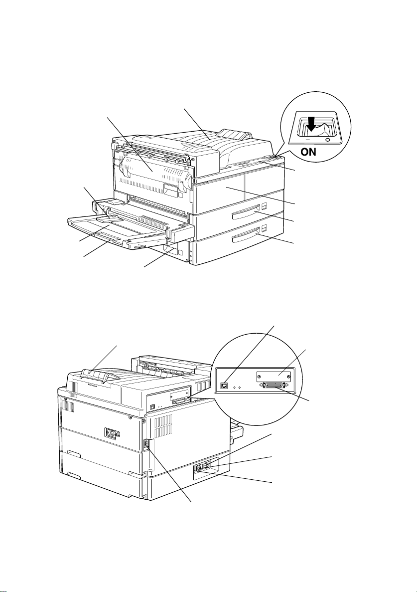
Printer Parts
power switch
cover A
paper guide
MP tray
extention
face-down tray
cover B
stopper
contr o l pan e l
front cover
lower cassette 1
lower cassette 2
Ethernet interface
connec tor
Type-B
interface
connector
parallel
interface
connector
AC inlet
optional Duplex Unit
connector
optional Multibin Unit
connector
optional Large
Capacity Paper Unit
connector
Page 3

®
Laser Printer
All rights reserved. No part of this publication may be reproduced, stored in a retrieval
system, or transmitted in any form or by any means, mechanical, photocopying, recording,
or otherwise, without the prior written permission of SEIKO EPSON CORPORATION. No
patent liability is assumed with respect to the use of the information contained herein.
Neither is any liability assumed fo r dam ages r e s u lting from the use of the inform ation
cont a ined herein.
Neither SEIKO EPSON CORPORATION nor its affiliates shall be liable to the purchaser of
this product or third parties for damages, losses, costs, or expenses incurred by purchaser
or third parties as a result of: accident, misuse, or abuse of this product or unauthorized
modifications, repairs, or alterations to this product, or (excluding the U.S.) failure to strictly
comply with SEIKO EPSON CORPORATION's operating and maintenance instructions.
SEIKO EPS ON CORPO RATION sh all no t be lia ble ag ainst an y dama ges or p roble ms aris ing
from the use of any options or any consumable products other than those designated as
Original EPSON Products or EPSON Approved Products by SEIKO EPSON
CORPORATION.
EPSON and EPSON ESC/P are registe red trademarks and EPSON ESC/P 2 is a trademark
of SEIKO EPSON CORPORATION.
Speedo, Fontware, FaceLift, Swiss, and Dutch are trademarks of Bitstream Inc.
CG Times and CG Omega are registered trademarks of Miles, Inc.
Univers is a registered trademark of L inotype AG and/or its subsid iaries.
Antique Olive is a trademark of Fonderie Olive.
Albertus is a trademark of Monotype Corporation plc.
Coronet is a trademark of Ludlow Industries (UK) Ltd.
Arial and Times New Roman are registered trademarks of Monotype Corporation plc.
HP and HP LaserJet are registered trademarks of Hewlett-Packard Company.
Adobe and PostScript are trademarks of Adobe Systems Incorporated, which may be
registered in certain jurisdictions.
General Notice:
may be trademarks of their respective owners. EPSON disclaims any and all rights in those
marks.
Copyright © 1998 by SEIKO EPSON CO RP ORATION, Nagano, Jap an.
Other product names used herein are for identification purposes only and
Reference Guide
Page 4

Declaration of Conformity
According to ISO/IEC Guide 22 and EN 45014
Manufacturer: SEIKO EPSON CORPORATION
Address: 3-5, Owa 3-chome, Suwa-shi,
Nagano-ken 392-8502 Japan
Representative: EPSON EUROPE B.V.
Address: Prof. J. H. Bavincklaan 5 1183
AT Amstelveen
The Netherlands
Declares that the Product:
Product Name: Laser Printer
Model: XYB-1
Conforms to the following Directive(s) and Norm(s):
Directive 89/336/EEC:
EN 55022 Class B
EN 50082-1
IEC 801-2
IEC 801-3
IEC 801-4
Directive 73/23/EEC:
November 1998
H. Horiuchi
President of EPSON EUROPE B.V.
EN 60950
Page 5

Contents
Getting Started
About This Guide . . . . . . . . . . . . . . . . . . . . . . . . . . . . . . . . . . . . . . . 2
About Your Printer . . . . . . . . . . . . . . . . . . . . . . . . . . . . . . . . . . . . . .3
Features . . . . . . . . . . . . . . . . . . . . . . . . . . . . . . . . . . . . . . . . . . .3
Options. . . . . . . . . . . . . . . . . . . . . . . . . . . . . . . . . . . . . . . . . . . .4
ENERGY STAR Compliance . . . . . . . . . . . . . . . . . . . . . . . . . . . . . .6
About Making Printer Settings . . . . . . . . . . . . . . . . . . . . . . . . . . . .6
Printer driver. . . . . . . . . . . . . . . . . . . . . . . . . . . . . . . . . . . . . . . 7
OneTouch modes . . . . . . . . . . . . . . . . . . . . . . . . . . . . . . . . . . .7
SelecType. . . . . . . . . . . . . . . . . . . . . . . . . . . . . . . . . . . . . . . . . .7
Safety Information. . . . . . . . . . . . . . . . . . . . . . . . . . . . . . . . . . . . . . .8
Ozone safety . . . . . . . . . . . . . . . . . . . . . . . . . . . . . . . . . . . . . . .1 0
Laser Printer Precautions . . . . . . . . . . . . . . . . . . . . . . . . . . . . . . . . .11
Important Safety Instructions . . . . . . . . . . . . . . . . . . . . . . . . . . . . . 13
For United Kingdom Us ers . . . . . . . . . . . . . . . . . . . . . . . . . . . . . . .15
Warnings, Cautions, and N o tes. . . . . . . . . . . . . . . . . . . . . . . . . . . . 16
Chapter 1
Caution About Turning Of f the Printer . . . . . . . . . . . . . . . . . . . . .1-2
Choosing Paper . . . . . . . . . . . . . . . . . . . . . . . . . . . . . . . . . . . . . . . . .1-2
Basic Printing Operations. . . . . . . . . . . . . . . . . . . . . . . . . . . . . . . . . 1-4
Special Printing Operations . . . . . . . . . . . . . . . . . . . . . . . . . . . . . . .1-11
Printing with the EPL-N400 0
Labels . . . . . . . . . . . . . . . . . . . . . . . . . . . . . . . . . . . . . . . . . . . . .1 -3
Envelopes. . . . . . . . . . . . . . . . . . . . . . . . . . . . . . . . . . . . . . . . . .1 -3
Colored paper . . . . . . . . . . . . . . . . . . . . . . . . . . . . . . . . . . . . . .1 -3
Transparencies . . . . . . . . . . . . . . . . . . . . . . . . . . . . . . . . . . . . .1-3
Loading paper in the MP (Multi Purpose) tray . . . . . . . . . .1-4
Loading paper in the lower cassettes . . . . . . . . . . . . . . . . . .1-6
Selecting the paper size . . . . . . . . . . . . . . . . . . . . . . . . . . . . . .1-10
Loading an uncommon paper size. . . . . . . . . . . . . . . . . . . . . 1-11
Printing one sheet at a time. . . . . . . . . . . . . . . . . . . . . . . . . . .1-12
Offset stacking mode . . . . . . . . . . . . . . . . . . . . . . . . . . . . . . . .1 -13
i
Page 6

Chapter 2
The Control Panel. . . . . . . . . . . . . . . . . . . . . . . . . . . . . . . . . . . . . . . 2-2
Using the OneTouch Modes . . . . . . . . . . . . . . . . . . . . . . . . . . . . . . 2-7
Control Panel
Overview . . . . . . . . . . . . . . . . . . . . . . . . . . . . . . . . . . . . . . . . . 2-2
Display . . . . . . . . . . . . . . . . . . . . . . . . . . . . . . . . . . . . . . . . . . . 2-2
Indicator lights. . . . . . . . . . . . . . . . . . . . . . . . . . . . . . . . . . . . . 2-3
Buttons . . . . . . . . . . . . . . . . . . . . . . . . . . . . . . . . . . . . . . . . . . . 2-4
OneTouch mode 1 . . . . . . . . . . . . . . . . . . . . . . . . . . . . . . . . . . 2-7
OneTouch mode 2 . . . . . . . . . . . . . . . . . . . . . . . . . . . . . . . . . . 2-8
Making OneTouch settings . . . . . . . . . . . . . . . . . . . . . . . . . . 2-8
Chapter 3
Printer Options . . . . . . . . . . . . . . . . . . . . . . . . . . . . . . . . . . . . . . . . . 3-2
Installing and Removing Options . . . . . . . . . . . . . . . . . . . . . . . . . 3-3
Using the Options. . . . . . . . . . . . . . . . . . . . . . . . . . . . . . . . . . . . . . . 3-57
Chapter 4
When to Use SelecType . . . . . . . . . . . . . . . . . . . . . . . . . . . . . . . . . . 4-2
Using SelecType . . . . . . . . . . . . . . . . . . . . . . . . . . . . . . . . . . . . . . . . 4-3
SelecType Menus . . . . . . . . . . . . . . . . . . . . . . . . . . . . . . . . . . . . . . . 4-4
Options
Large Capacity Paper Unit. . . . . . . . . . . . . . . . . . . . . . . . . . . 3-3
Duplex Unit . . . . . . . . . . . . . . . . . . . . . . . . . . . . . . . . . . . . . . . 3-10
Face-up Tray. . . . . . . . . . . . . . . . . . . . . . . . . . . . . . . . . . . . . . . 3-16
Envelope Feeder . . . . . . . . . . . . . . . . . . . . . . . . . . . . . . . . . . . 3-28
Multibin Unit . . . . . . . . . . . . . . . . . . . . . . . . . . . . . . . . . . . . . . 3-32
Memory modules . . . . . . . . . . . . . . . . . . . . . . . . . . . . . . . . . . 3-47
ROM module . . . . . . . . . . . . . . . . . . . . . . . . . . . . . . . . . . . . . . 3-53
Optional interfaces . . . . . . . . . . . . . . . . . . . . . . . . . . . . . . . . . 3-54
Large Capacity Paper Unit. . . . . . . . . . . . . . . . . . . . . . . . . . . 3-57
Duplex Unit . . . . . . . . . . . . . . . . . . . . . . . . . . . . . . . . . . . . . . . 3-58
Face-up Tray. . . . . . . . . . . . . . . . . . . . . . . . . . . . . . . . . . . . . . . 3-58
Envelope Feeder . . . . . . . . . . . . . . . . . . . . . . . . . . . . . . . . . . . 3-60
Multibin Unit . . . . . . . . . . . . . . . . . . . . . . . . . . . . . . . . . . . . . . 3-61
SelecType
ii
Page 7

SelecType Settings. . . . . . . . . . . . . . . . . . . . . . . . . . . . . . . . . . . . . . .4-7
Test Menu . . . . . . . . . . . . . . . . . . . . . . . . . . . . . . . . . . . . . . . . .4 -7
Emulation Menu. . . . . . . . . . . . . . . . . . . . . . . . . . . . . . . . . . . .4-8
Printing Menu. . . . . . . . . . . . . . . . . . . . . . . . . . . . . . . . . . . . . . 4 -8
Tray Menu . . . . . . . . . . . . . . . . . . . . . . . . . . . . . . . . . . . . . . . . .4-11
Config Menu . . . . . . . . . . . . . . . . . . . . . . . . . . . . . . . . . . . . . . .4-13
Setup Menu . . . . . . . . . . . . . . . . . . . . . . . . . . . . . . . . . . . . . . . .4-16
Parallel Menu . . . . . . . . . . . . . . . . . . . . . . . . . . . . . . . . . . . . . . 4 -19
Network Menu . . . . . . . . . . . . . . . . . . . . . . . . . . . . . . . . . . . . .4-20
AUX Menu. . . . . . . . . . . . . . . . . . . . . . . . . . . . . . . . . . . . . . . . .4-21
LJ4 Menu . . . . . . . . . . . . . . . . . . . . . . . . . . . . . . . . . . . . . . . . . .4 -21
GL2 Menu . . . . . . . . . . . . . . . . . . . . . . . . . . . . . . . . . . . . . . . . .4-23
PS3 Menu. . . . . . . . . . . . . . . . . . . . . . . . . . . . . . . . . . . . . . . . . .4-25
ESCP2 and FX Menus . . . . . . . . . . . . . . . . . . . . . . . . . . . . . . .4-26
I239X Menu . . . . . . . . . . . . . . . . . . . . . . . . . . . . . . . . . . . . . . . . 4-29
Chapter 5
Introduction . . . . . . . . . . . . . . . . . . . . . . . . . . . . . . . . . . . . . . . . . . . . 5-2
Preventing Paper Feed and P ap er Jam Problems. . . . . . . . . . . . . 5-2
Clearing Paper Jams . . . . . . . . . . . . . . . . . . . . . . . . . . . . . . . . . . . . .5-3
Print Quality Problems . . . . . . . . . . . . . . . . . . . . . . . . . . . . . . . . . . .5- 17
Option Problems . . . . . . . . . . . . . . . . . . . . . . . . . . . . . . . . . . . . . . . . 5-20
Other Problems . . . . . . . . . . . . . . . . . . . . . . . . . . . . . . . . . . . . . . . . .5-21
Status and Error Messages . . . . . . . . . . . . . . . . . . . . . . . . . . . . . . . .5-24
Hex Dump Mode. . . . . . . . . . . . . . . . . . . . . . . . . . . . . . . . . . . . . . . .5-35
Replacing the Imaging Cartridge . . . . . . . . . . . . . . . . . . . . . . . . . . 5-36
Optimizing Print Quality . . . . . . . . . . . . . . . . . . . . . . . . . . . . . . . . . 5-40
Resetting the Printer . . . . . . . . . . . . . . . . . . . . . . . . . . . . . . . . . . . . .5-42
Cleaning the Printer . . . . . . . . . . . . . . . . . . . . . . . . . . . . . . . . . . . . . 5-42
Transporting the Printer. . . . . . . . . . . . . . . . . . . . . . . . . . . . . . . . . .5-44
Troubleshootin g and Maintenance
Resolution Improvemen t Te chno log y. . . . . . . . . . . . . . . . . .5-40
Adjusting print density . . . . . . . . . . . . . . . . . . . . . . . . . . . . . .5 -40
Enhanced MicroGray . . . . . . . . . . . . . . . . . . . . . . . . . . . . . . . .5-41
Cleaning inside cover A. . . . . . . . . . . . . . . . . . . . . . . . . . . . . .5-43
Cleaning the printer case. . . . . . . . . . . . . . . . . . . . . . . . . . . . .5-44
Finding a new place for the printer . . . . . . . . . . . . . . . . . . . .5-45
iii
Page 8

Appendix A
Paper Specifications . . . . . . . . . . . . . . . . . . . . . . . . . . . . . . . . . . . . . A-2
Printer. . . . . . . . . . . . . . . . . . . . . . . . . . . . . . . . . . . . . . . . . . . . . . . . . A-4
General . . . . . . . . . . . . . . . . . . . . . . . . . . . . . . . . . . . . . . . . . . . A-4
Environmental . . . . . . . . . . . . . . . . . . . . . . . . . . . . . . . . . . . . . A-5
Mechanical . . . . . . . . . . . . . . . . . . . . . . . . . . . . . . . . . . . . . . . . A-5
Electrical . . . . . . . . . . . . . . . . . . . . . . . . . . . . . . . . . . . . . . . . . . A-5
Interface . . . . . . . . . . . . . . . . . . . . . . . . . . . . . . . . . . . . . . . . . . . . . . . A-6
Parallel interface . . . . . . . . . . . . . . . . . . . . . . . . . . . . . . . . . . . A-6
Ethernet Interface . . . . . . . . . . . . . . . . . . . . . . . . . . . . . . . . . . A-12
Options and Consumables . . . . . . . . . . . . . . . . . . . . . . . . . . . . . . . A-13
Large Capacity Paper Unit (C81303✽) . . . . . . . . . . . . . . . . . A-13
Duplex Unit (C81304✽). . . . . . . . . . . . . . . . . . . . . . . . . . . . . . A-14
Multibin Unit (C81305✽) . . . . . . . . . . . . . . . . . . . . . . . . . . . . A-15
Face-up Tray (C81306✽) . . . . . . . . . . . . . . . . . . . . . . . . . . . . . A-15
Envelope Feeder (C81307✽). . . . . . . . . . . . . . . . . . . . . . . . . . A-16
Imaging Cartridge (S051060) . . . . . . . . . . . . . . . . . . . . . . . . . A-16
Technical Specifications
Appendix B
Introduction to Symbol Sets . . . . . . . . . . . . . . . . . . . . . . . . . . . . . . B-2
In LJ4 Emulation Mode . . . . . . . . . . . . . . . . . . . . . . . . . . . . . . . . . . B-3
International Set for ISO sets . . . . . . . . . . . . . . . . . . . . . . . . . B-21
In ESC/P 2 or FX Mode . . . . . . . . . . . . . . . . . . . . . . . . . . . . . . . . . B-22
International character sets . . . . . . . . . . . . . . . . . . . . . . . . . . B-26
Characters available with the ESC (^ command . . . . . . . . B-27
In I239X Emulation Mode . . . . . . . . . . . . . . . . . . . . . . . . . . . . . . . . B-28
In EPSON GL/2 Mo de. . . . . . . . . . . . . . . . . . . . . . . . . . . . . . . . . . . B-28
Appendix C
LaserJet 4 (LJ4) Emulation Commands . . . . . . . . . . . . . . . . . . . . . C-2
GL/2 context command s . . . . . . . . . . . . . . . . . . . . . . . . . . . . C-6
ESC/P 2 and FX Commands . . . . . . . . . . . . . . . . . . . . . . . . . . . . . C-8
ESC/P 2 mode . . . . . . . . . . . . . . . . . . . . . . . . . . . . . . . . . . . . . C-8
FX mode . . . . . . . . . . . . . . . . . . . . . . . . . . . . . . . . . . . . . . . . . . C-11
PJL Commands . . . . . . . . . . . . . . . . . . . . . . . . . . . . . . . . . . . . . . . . . C-14
Symbol Sets
Command Su mmary
iv
Page 9

I239X Emulation Commands. . . . . . . . . . . . . . . . . . . . . . . . . . . . . .C-15
Page format . . . . . . . . . . . . . . . . . . . . . . . . . . . . . . . . . . . . . . . .C-15
Text . . . . . . . . . . . . . . . . . . . . . . . . . . . . . . . . . . . . . . . . . . . . . . . C -16
Auxiliary functions. . . . . . . . . . . . . . . . . . . . . . . . . . . . . . . . . .C-17
AGM mode . . . . . . . . . . . . . . . . . . . . . . . . . . . . . . . . . . . . . . . .C-18
Appendix D
Printer and Screen Fonts . . . . . . . . . . . . . . . . . . . . . . . . . . . . . . . . . .D-2
Available Fonts . . . . . . . . . . . . . . . . . . . . . . . . . . . . . . . . . . . . . . . . . D-3
Adding More Fonts . . . . . . . . . . . . . . . . . . . . . . . . . . . . . . . . . . . . . . D-6
Downloading fonts. . . . . . . . . . . . . . . . . . . . . . . . . . . . . . . . . .D-6
Selecting Fonts . . . . . . . . . . . . . . . . . . . . . . . . . . . . . . . . . . . . . . . . . .D-6
Appendix E
Switching between SelecType Menus . . . . . . . . . . . . . . . . . . . . . .E-2
Working with Fonts
Map of SelecType Menus
Glossary
Index
v
Page 10

vi
Page 11

Getting Started
The EPSON EPL- N40 00 p ri nter combines high performanc e an d
reliability with a wide ran ge of features.
To get starte d with your laser printer, please:
❏ Read the s a fety informat ion, laser printe r precautions, a nd
important safety instructions in this section.
❏ Use your
printer.
❏ Have your network administrator refer to the
Guide to
Guide
❏ Atta ch the small box included in yo u r p r i n te r p a ck age to the
front of the printer. Keep the
for help on understanding printer messages, cl e aring paper
jams, and replacing the imaging ca rtridge.
Refer to this
printer.
Hardware Setup Guide
make network settin gs. Also see the
for instructions on installing printer software.
Reference Guide
for detailed information about your
to set up and test your ne w
Administrator’s
Administrator’s
Quick Reference Guide
in this box
Getting Started
1
Page 12

About This Guide
This guide contains the following information.
Chapter 1, “Printin g with the EP L-N4000,” contains information
on general printing operation. Also contains information about
printing on special media.
Chapter 2, “Control Panel,” explains the contents of the printer’s
control pa nel and how to use the OneTouch Mode s.
Chapter 3, “Options,” gives step-by-step instructions for
installing the printer options. Also describes how to use the
options.
Chapter 4, “SelecType , ” describes the settin gs you can make in
SelecType on the c ontrol panel. Read this chapter if you cannot
modify a printer setting from your software.
Chapter 5, “Troubleshooting and Maintenance,” gives helpful
information for what to do if you enco unter a printe r error and
provides instructions on how to maintain your printer.
Appendix A, “Technical Specifications,” contains technical
information about your printer and options.
Appendix B, “Symbol Sets,” lists the symbol sets available in each
emulation mode with tables of the characters for each set.
Appendix C, “Command Summary,” l ists the commands that can
be embedded in print j obs t o control the printer. This appendix is
intended for advanced users only.
Appendix D, “Working with Fonts,” describes the steps you need
to follow to add more fonts. Also lists the available fonts with
samples.
Appendix E, “Map of SelecType Menus,” lists the SelecType
menus and the order i n which you a ccess t hem. T his app endix is
useful when you use SelecType.
2
Getting Started
Page 13

About Your Printer
Your printer is the latest in EPSON’s advanced line of network
laser pri nters. It emul ates the Hewlett-Packard
(LJ4) printer, allowing you to print using the wide variety of
software programs th at support HP L aserJet printe rs.
The printer’s 600-dpi (dots per inch) resolution is enhanced by
EPSON’s Resolution Improvem ent Tech nology (RITech), which
smooths the jagged edges of diagonal lines in both text and
graphics. This gives your do cuments a clean , crisp, professional
appearance.
In addition, EPSON’s Enhance MicroGray technology provides
you with b e tte r halftoning when printing graphics.
This print er is intended to be used on network environments.
After your administrator makes network settings, install t he
printer software as instructed b y your administrator. The
Administrator’s Guid e
printer p ac ka g e .
The printer supports ECP mode in Microsoft
mode is useful for high-speed data transfer and bidirectional
communi cation with yo ur computer.
is includ ed for your administrator in the
®
LaserJet 4™
®
Window s® 95. ECP
Features
The printe r comes with a full set of fea tures that contributes to
ease of use and consiste nt, high-quality out put. The main features
are described below.
High-quality printin g
Your printer provides 600 -dpi printing at a speed of up to 40 pages
per minute. You’ll appreciate the professional print quality
produced by your printer and its quick processing speed.
Getting Started
3
Page 14

Wide variety of fonts
The printer comes with a full selection of scalable TrueType®
fonts, LaserJet-c ompat ible s cal able fonts , and one bi tmap font in
LJ4 emulation mode, to provide you with the fonts you need to
create professional-looking documents.
Toner Save mode
You can reduce the amount of toner used by printing rough drafts
using the T oner Save mod e .
Options
Memory
The printer comes with 16 MB of memory, which can be expanded
to up to 256 MB.
Interface
The printer comes with a built-in bidirectional parallel inte rface
and a built-in Ethernet interface. You can install an optional
interface card.
Rom module
®
The Adobe
generates crisp PostScript output. Installation instruction s are
included in this
documentation.
Note:
The asterisk (
which varies by country .
4
Getting Started
PostScript® 3™ Kit (C83232✽) ROM module
Reference Guide.
✽
) is a substitute for the last digit of the product number,
See also the PostScript Kit’s
Page 15

Paper Sources
The Large Capaci ty Paper Unit ( C81303✽), wh ich inclu des lower
paper cassettes 3, 4 , and 5, allows you to preload up to 35 50 sheets
of paper in combination with the standard paper sources.
MP (Mul ti Purpose) tray (standard ) 50
Lower Cassette 1 (standard) 500
Lower Cassette 2 (standard) 500
Lower Cassette 3 (option) 500
Lower Cassette 4 (option) 1000
Lower Cassette 5 (option) 1000
3550
Envelope Feeder
The Envelope Feeder (C81307✽) prints on various sizes of
envelop es. This opti on cannot be used with the MP tray.
Duplex Unit
The Duplex Unit (C81304✽) prints on both sides of paper.
Output tr ays
The Multibin Unit (C81305✽) can be used as a sorter, a multiple
sorter, a mail box, or a large capacity stacker. This 10-bin unit
accommodates up to 1000 printed sheets in total.
The Face-up Tray ( C81306 ✽) holds up to 200 print ed sheets with
the printed side up.
When used in combination with the standard face-down tray,
these options can handle up to 1700 printed sheets.
Face-down Tray (standard) 500
Face-up Tray (option) 200
Multibin Unit (option) 1000
1700
Getting Started
5
Page 16

NERGY STAR Compliance
E
As an ENERGY STAR Partner , EPSON
has dete rmi ned that this product meets
the ENERGY STAR guidelines for energy
efficiency.
The Internati onal ENERGY ST AR Office Equipment Program is
a voluntary partnership with the computer and office equipment
industry to promote the introduction of energy-efficient personal
comput ers, monitors, printers, fax machine s, copiers, and
scanner s, in an effort to reduce air pollution cau se d by power
generation .
About Making Printer Settings
You need to make some settings for your printer before printing.
There are three ways you can make these settings:
❏ Using your printer driver (software that runs or “drives” your
printer)
❏ Using the OneTouch modes (control panel shortcuts that
allow you to make several settings quickly)
❏ Using SelecType (control panel functions that allow you to
make even more settings than the printer driver)
If you use a Windows application, us e the printer driv er that came
with the p rinter to make settings. For details on yo ur printer
driver, see the driver’s online help.
If you cannot make all the settings you need thro ugh the
Windows printer driver, use the OneTouch modes and
SelecType.
6
Getting Started
Page 17

Printer driver
Use the printer driver to easily and conveniently make new
printer settings. Most users may never need to use anything other
than their a pplication so ftware and the printer driver to make
printer set tings. You ca n access the p rinter driver through an
application’s Pr int command, or by choosing your pr inter in your
operating system’s Printers folder or program group. Be aware
that settings you make in your application so ftware overri de
printer driver settings. See the driver’s online help for mo re
information.
OneTouch modes
Use the OneTouch modes on the printer control panel to make
printer settings when you cannot make a setting in your
application soft ware or printer driv er. The OneTou ch modes are
the easiest way to make several basic settings from the printer’s
control panel; however, any settings that can be made in your
softwar e application or printer dri ver overrid e c orresponding
OneTouch mode settings. See “Using the OneTouch Modes” on
page 2-7 for more information.
SelecType
Use the SelecType buttons on the printer’s control panel to make
printer settings when you cannot make a setting in your
application software or printer driver. SelecType has more
detailed op tions than t he OneTouch modes but it may t ake a few
extra steps to make those settings. See “Using SelecType” on page
4-3 for more information.
Getting Started
7
Page 18

Safety Information
Laser safety
This printe r is certified a s a Class 1 laser product under the U.S.
Department of Health and Human Services (D HHS) Radiatio n
Performance Standa rd according to the Radiati on Control for
Health and Safety Act of 1968. This means that the printer does
not produce hazardous laser radiation.
Since radiation emitted by the laser is completely confined within
protective housings and external covers, the laser beam cannot
escape from the machine during any phase of user operation.
The EPL-N4000 is a page printer whi ch u ti lizes a s emicon ductor
laser.
There is no possibility of danger from the laser, provided th e
printer is operated according to the instructions in the guides
provided.
Since radiation emitted by the laser is completely confined within
protective housings, the laser beam cannot escape from the
machine during any phase of user operation.
Warning:
w
Use of controls or adjustments or performance of procedures
other than those specified in this guide, may result in hazardous
radiation exposure.
This is a se mi conductor laser. The ma ximum power of the laser
diode is 5 mW with a wavelength of
8
Getting Started
775 to 795
nm.
Page 19

CDRH regulations
The Center for Devices and Radiological Health (CDRH) of the
U.S. Food and Drug Administrati on implemented regulations for
laser products on August 2, 1976. Compliance is mandatory for
products marketed in the United States. The label shown below
indicates c ompliance with the CDRH regulations and must be
attached to laser products markete d in the Unite d S tates.
Laser safety labels
Warning:
w
Use of controls, adjustments, or performance of procedures other
than those specified in th is g uid e may result in hazardous
radiation exposure.
Your printer is a Clas s 1 laser product as defined in IEC 825
specifications. The label shown below is attached in countries
where required.
Getting Started
9
Page 20

Ozone safety
Ozone emission
Ozone gas i s generated by laser printers as a by-produc t o f the
printing process. Ozone is produced only when the printer is
printing.
Ozone exposure lim i t
The recommended exposure limit for ozone is 0.02 parts per
million (ppm) expressed as an average time-weighted
concentration over an eight (8) hour period.
The EPL-N4000 laser printer generates less than 0.01 ppm for 8
hours of continuous printing in a closed room of approximately
1000 cubic feet (8' × 10' × 12').
Minimize exposure risk
To minimize the ri sk of exposure to ozone:
❏ Do not use more than one laser printer in a confined area (see
Ozone e xposure limit
abov e)
❏ Do not use your printer in conditions of extremely low
humidity
❏ Do not use your printer in a room with poor ventilation
❏ Avoid long, continuous printing in any of the conditions
mentioned above
Printer location
The printe r should be loc ated so that the exhaust g ases and
generated heat are:
❏ Not blown directly into the user's face
❏ Vented directly out of the building whenever possible
10
Getting Started
Page 21

Laser Printer Precautions
This printer uses laser technology. The following list of
precautions applies whenever you open the printer cover.
Even if you are familiar with other types of printers, be sure
to follow these precautions carefully to ensure safe, efficient
operation.
❏ Do not touch the a reas specified o n the caution labels inside
cover A. If the printer has been in use, these areas can be very
hot.
CAUTION
Hot Surface Avoid Contact
❏ Do not touch the components inside the printer unless
instructed to do so in this gui de.
❏ Never force the printer's components into place. Although
the printer is designed to be sturdy, rough handling can
damage it.
❏ Be sure not to scratch the surface of the drum. When you
remove the imaging cartridge from the printer, always set the
unit on a clean, smooth surface. Also, avoid touching the
drum, since oils from your skin can permanently damage its
surface and may affect print quality.
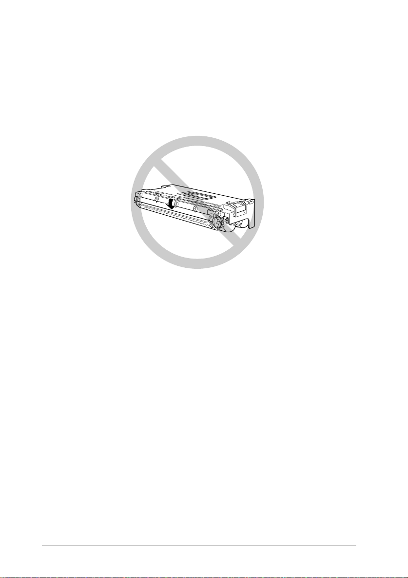
❏ Do not turn the cartridge upside down or stand it on its sides.
Getting Started
11
Page 22
❏ Protect the l ight-sensitive drum from exposure to light. Avoid
exposing the imaging cartridge to room light any longer than
necessa ry. Do not ope n the drum’s protective cover.
Overexposing the drum may cause abnormally dark or l ig ht
areas to appear on the printed page and reduce the service
life of the dr um.
❏ When handling the car tridge, always set it on a c lean, smooth
surface.
❏ Do not attempt to modify or take apart the cartridge. It cannot
be refilled.
❏ Do not touch the toner and avoid all contact with your eyes.
❏ Wait for at l e ast one hour be fore using a cartridge after
moving it from a c ool to a warm environment.
Warning:
w
Do not dispose of used imaging cart rid g es in fire, as they can
explode and cause injury. Dispose of them according to local
regulations.
Getting Started
12
Page 23

To get the b est print qual ity, do not sto re the imaging cartridge
in an area subject to dire ct sunlight, d ust, salty air, o r corrosive
gasses (such as ammonia). Avoid location s subject to high
temperatures, humidity, or ab rupt changes in temperature or
humidi ty . Al so, be sure t o k eep the consu ma ble compo nen ts out
of the reach of children.
Hinweis:
Die Geräteanschlußleitung muß den einshlägig en N ormen genügen.
Es muß eine dreiadrige Leitung v erwendet werden.
Die Anshlußlei tung da rf nicht l eichte r als H05 VV-F order H05VVH2F sein.
Maschinenlärmin formations- Verordnung-3 . GSGV, 18. 01. 1991: Der
arbeitsplatzbezogene schalldruckpegel beträgt 70 dB (A) oder weniger
gemäß ISO 7779.
Important Safety Instructions
Read all of these ins tr uctions before operating your printer.
❏ Follow all warnings and instructions marked on the printer.
❏ Unplug the printer from the wall outlet before cleaning.
❏ Use a damp cloth for cleaning and do n ot use liquid or aer osol
cleaners.
❏ Do not use this printer near water.
❏ Do not place the printer on an unstable cart, stand, or table.
❏ Slots and openings in the cabinet and the back or bottom are
provided for ven tilation . Do not bloc k or cover them. Do n ot
put the pri nter on a bed, sofa, rug, or other similar s urfaces
or in an enclosure unless proper ventilation is provided.
Getting Started
13
Page 24

❏ Use the type of power source indicated on the label. If you are
not sure of the type of power available, consult your dealer
or local power company.
❏ If you are unable to insert the plug into the outlet, contact your
electrician to have your outlet repaired or replaced.
❏ Do not put your printer where the cord might be stepped on.
❏ Avoid using outlets that other appliances are plugged in to.
❏ Only use an outlet that meets the power requirements for this
printer.
❏ Never push objects of any kind through cabinet slots as they
may touch dangerous volt age points or short out parts which
could result in fire or elect ric shock. Never spil l liquid of any
kind on the pri nter.
❏ Except as specifically expla ined in this guide, do not attempt
to service this product yourself. Opening or removing covers
that are marked “Do Not Remove” exposes you to dangerous
voltage. Refer all servicing in those compartments to service
personnel.
❏ Unplug the printer from the wall outlet and refer servicing to
qualified service personnel under the following conditions:
A. If liquid has been spilled into it.
B. If it has been exposed to rain or water.
C. If it does not operate normally when the operating
instructions are followed. Adjust only those controls that
are covered by the operatin g instructions since improper
adjustment of other controls may result in damage and
will often require extensive work by a qualified
technician to restore the product to normal operation.
D. If it has been dropped or the cabinet has been damaged.
14
Getting Started
Page 25

E. If it exhibits a distinct change in performance, indicating
a need for service.
F. W hen the power cord or plug is damaged or frayed.
For United Kingdom Users
Use of options
EPSON (UK) Li mite d s hal l not be liab l e agai ns t any damage s or
problems arising from the use of any options or consumable
products other than those designated as Original EPSON
Products or EPSON Approved Products by EPSON (UK)
Limited.
Safety information
Warning:
for voltage and check t hat th e ap p liance voltage corresponds to
the supply voltage.
Important:
coloured in accordance with the following code:
Green and yellow—Earth
Blue—Neutral
Brown—Live
If you need to fit a plug:
As the colours of the mai ns lead of this appliance may not matc h
any coloure d markings used to identify the terminals i n a plug,
please proceed as follows:
❏ The green and yellow w ire must be connected t o the terminal
This appliance must be earthed. Refer to rating plate
The wires in the m ains lead fitted to this appliance are
in the plug which is marked with the letter E or the Earth
G
symbol (
).
Getting Started
15
Page 26

❏ The blue wire mu st be connected to the terminal in the plug
marked w ith the letter N.
❏ The brown wire must be connected to the terminal in the plug
marked w ith the letter L.
If damage occurs to the plug, replace the cord set or consult a
qualified electrician.
Replace fuses only with a fuse of the correct size and rating.
Warnings, Cautions, and Notes
Warnings
must be followed c arefully to avoid bodily injury.
w
Cautions
must be observed to avoid damage to your equipment.
c
Notes
contain important informa tio n and useful tips on the operation
of your printer.
16
Getting Started
Page 27

Chapter 1
Print i ng with the EPL - N 4000
Caution About Turning Of f the Printer . . . . . . . . . . . . . . . . . . . . . . 1-2
Choosing Paper . . . . . . . . . . . . . . . . . . . . . . . . . . . . . . . . . . . . . . . . . .1-2
Labels . . . . . . . . . . . . . . . . . . . . . . . . . . . . . . . . . . . . . . . . . . . . . . 1-3
Envelopes. . . . . . . . . . . . . . . . . . . . . . . . . . . . . . . . . . . . . . . . . . .1-3
Colored paper . . . . . . . . . . . . . . . . . . . . . . . . . . . . . . . . . . . . . . . 1- 3
Transparencies . . . . . . . . . . . . . . . . . . . . . . . . . . . . . . . . . . . . . . 1-3
Basic Printing Operations. . . . . . . . . . . . . . . . . . . . . . . . . . . . . . . . . . 1-4
Loading paper in the MP (Multi Purpose) tray . . . . . . . . . . . 1-4
Loading paper in the lower cassettes . . . . . . . . . . . . . . . . . . . 1-6
Selecting the paper size . . . . . . . . . . . . . . . . . . . . . . . . . . . . . . . 1-10
Special Printing Operations . . . . . . . . . . . . . . . . . . . . . . . . . . . . . . . . 1-11
Loading an uncommon paper size. . . . . . . . . . . . . . . . . . . . . . 1-11
Printing one sheet at a time. . . . . . . . . . . . . . . . . . . . . . . . . . . . 1-12
Offset stacking mode . . . . . . . . . . . . . . . . . . . . . . . . . . . . . . . . .1-13
1
Printing with the EPL-N4000
1-1
Page 28

Caution About Turning Off the Printer
Caution:
c
Do not turn off the printer:
❏ For at least 60 seconds after tu rning on the printer. Wait
until Ready appears on the displa y pa nel.
❏ While the On Line light is blinking.
❏ While the Form Feed lig ht is on or blinking.
Choosing Paper
Note:
Since the qual ity of any particula r brand or type of pa per may be changed
by the manufacturer at any time, EPSON cannot guarantee the quality
of any type of paper. Always test samples of paper stock before purchasing
large quantities or printi ng large jobs.
You can use ma ny kinds of media including stock paper,
envelopes, labels, and overhead projector transparencies. The
printer automatically feeds most types of media from the MP
(Multi P urpose) Tr ay, except f or envelop es. This sec tion desc ribes
each paper feed, which one to use, and how to select and load
paper.
The type of paper you use in your printer can affect the quality of
your printe d output. The smoother the pape r yo u use, the
smoother and sharper your printing looks.
For best r e su lt s, st or e you r pape r sup ply in its original wra pp e r .
Your printout can be marred by moisture absorbed in the paper.
Do not store paper in a humid or damp environment.
Following are some recommendations for selecting paper and
other print media for the pri nter.
1-2
Printing with the EPL-N4000
Page 29

Labels
Use only labels designed for laser printers or plain-paper copiers.
Use the MP tray and lower cassettes to print on t hese material s.
To prevent the adhesiv e from coming in contact with printer
parts, always use labels that comp letely cover the backing sheet
so that no ga ps occur betwee n the individual labels.
Test the label sheet for leaking adhesive by pressing a sheet of
paper on top of a sheet of labels. If the paper sticks to the label
sheet when you lift it off, do not use the labels.
Envelopes
Printing quality on envelopes may be irregular because different
parts of an envelope have different thicknesses. If the printing is
too light, adjust the print density in the printer driver or the
printer’s co ntrol panel.
Note:
Because thickness and surf ace cha racteristics are especially important
for envelopes, test a sample for print quality and proper feeding before
you buy a large numb er of en vel opes.
1
Colored paper
You can use colored paper as long as it meets the weight limits
shown in the paper specifications. Do not, however, use coated
paper (paper to which a clear or colo red coati ng has been added) .
Transparencies
You can use overhead projector transparencies and adhesive
drafting film if they are made for use with plain-paper copiers or
laser printers. Load these media into a lowe r cassette or the MP
tray.
Printing with the EPL-N4000
1-3
Page 30

Basic Printing Operations
This section covers how to use the standard paper sources. See
Chapter 3, “Options” for information on optional paper sources
and output trays.
Loading paper in the MP (Multi Purpose) tray
The MP tray accommodates various types and sizes of paper and
handles up to 50 sheets of 75 g/m
This tray is useful when printing on paper that you don’t
regularly use. Refer to the table below to load your paper with the
correct orientation.
Loading Orientation Paper Size
Horizontal A4, B5, A5, Letter, Government Letter, Half-
Letter, International B5, Executive
Vertical A3, B4, F4, Ledger, Legal, Government Legal,
To confirm paper size dimensions, s ee Appendix A, “Paper Spe cifications”.
Horizontal loading orientation Vertical loading orient ation
2
, or a st ack of pape r 5 mm thick.
Caution:
c
To load paper i n the MP tray, fo l low the steps below.
1-4
Always use the optional Envel ope Feed er when you print on
envelopes of sizes other than International B5.
Printing with the EPL-N4000
Page 31

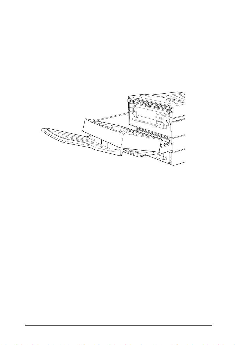
1. Open the MP tray if it is closed against the body of the printer.
Pull out the extension i f necessary.
2. Fan a stack of paper and tap it on a flat surface to even its
edges. With the printable side down, load the stack by
inserting it all the way into the tray. Make sure the paper lies
below the arrows on the paper guide. Adjust the guide to
match the size of your paper.
1
printable side
down
Caution:
c
3. Select the p aper size and type on the control panel. Press the
Menu
the
select the paper size, then press
next to the active setting. Then press the
MP Type appears and repeat the same procedure to set the
paper type. Press the
Make sure to adjust the paper guides to the paper size you
load; otherwise, the print er will not print properly.
button until Tray Menu appears on the display , the n
Item
button until MP Tray Size appears. Press
Enter
. An asterisk (✽) appears
On Line
button to return to Ready.
Printing with the EPL-N4000
Menu
Value
button until
to
1-5
Page 32

Loading paper in the lower cassettes
Lower cassettes 1 and 2 ac commod ate var iou s ty pes an d s izes o f
paper. These cassettes are useful for loading paper that you use
regularly or in large amounts. Each cassette handles 500 sheets
allowing you to load a total of 1000 sheets. Refer to the tables
below to load your paper wi th the correct orientation in the
appropriate cassette.
Lower Ca ssette 1
Loading Orientation Paper Size
Vertical A4, A5, Executive, Letter, Hal f-Letter
Horizontal A3, Ledger, Legal, Government Legal
Lower Ca ssette 2
Loading Orientation Paper Size
Vertical A4, Executive, Letter
Horizontal A3, Ledger, Legal, Government Legal
To confirm paper size dimensions, s ee Appendix A, “Paper Spe cifications”.
Vertical loading orientation Horizontal loading orientation
Caution:
c
To load paper in a lower cassette, follow the steps below.
1-6
You cannot print on envelopes using the lower cassettes.
Printing with the EPL-N4000
Page 33

1. Pull out the cassette that you want to load.
2. While pulling up t he vert ical paper g uide, slid e it outwa rd as
far as it will go.
1
3. While pushing down the leve r on the horizontal paper gui de,
slide it outward as far as it will go.
Printing with the EPL-N4000
1-7
Page 34

4. Fan a stack of paper and tap it on a flat surface to even its
edges. Insert the paper face up into the cassette, placing the
corners of the paper on the arrow mark inside the cassette.
printable s ide up
Note:
Be sure not to load paper higher than the arrow marks.
5. Adjust the vertical and horizontal paper guides to match the
size of your paper.
1-8
Caution:
c
Printing with the EPL-N4000
Make sure to adjust the paper guides to the paper size you
load; otherwise, the printer will not print properly.
Page 35

6. Take out the card with paper sizes printed on it. Fold the card
and insert it into the cassette to show the paper size that you
loaded.
7. Push the cassette ba ck into the printer.
1
Printing with the EPL-N4000
1-9
Page 36

Selecting the paper size
By default, the printer driver is set for A4 size paper to be loaded.
If you load pa per of a d ifferent s ize, ch ange the paper s ize set ting
using one of the following methods.
Using the printer driver
Choose the paper size on the Basic Settings menu. For m ore
information on using the printer driver, see the driver’s online
help.
Using Se lecType
On the pri nte r’s control panel, press the
Printing Menu appears in the display. T hen press
Size appears . Press
press th e
appears next to the activated setting.
Enter
Value
to change the paper size setting, then
button to activate your se tting. An aste risk (✽)
Menu
button until
Item
until Page
1-10
Printing with the EPL-N4000
Page 37

Special Printing Operations
Read this secti on to learn how to loa d paper of an uncommon size,
to print one sheet at a time , o r to separate print jobs using offset
stacking.
Loading an uncommon paper size
Use the MP tray to load paper with a horizontal measurement
(side A below) of 100 to 297 mm (3.9 × 11.7 in.), or a vertical
measurement (side B below) of 139.7 to 431.8 mm (5.5 × 17 in.).
Make your custom paper size settings in one of the following
methods.
1
A
❏ In the Basic Settings me nu of the printer driver , se lect
Defined Size
Paper Length, and Unit settings for your custom paper. Then
click OK to save yo ur settings.
❏ Access the SelecType mode using the control panel on your
printer (se e “Using SelecT ype” on page 4-3) and s et the Page
Size to
in the Paper list box. Type the Paper Width,
CTM
(custom).
Printing with the EPL-N4000
B
User
1-11
Page 38

Printing one sheet at a time
You can print one sheet at a time in the Manual Feed mode. This
mode is he lpful when you want to check the print qualit y after
each page is printed.
To print in the manual feed mode, follow the steps below.
1. Acce ss the printer driver.
Note:
If you have not installed t he printer driver, install it as instructed
by your administrator. The "Administrator’s Guide" is included in
this printer package for your ad m inist rat or.
2. In the Basic Settings menu, select the Manual Feed check box.
3. In the Paper box, scroll through the list of paper sizes and click
the size that matches the paper you will load in the printer.
4. Insert a sheet or stack of the correct size paper into the desired
paper source. Adjust the paper guides to match the paper size
you are load ing.
5. Send a print job from your application. The control panel
display shows Manual Feed and the selected page size.
6. Press
7. Press
1-12
Printing with the EPL-N4000
On Line
fed and printed.
On Line
necessary. Repeat this step for every page to be printed.
on your printer to print. The sheet of paper is
again to pri nt the next page of print data , if
Page 39

Offset stacking mode
The offset stacking mode allow s you to separate print jobs, or
multiple copies of your document, by alternating their positions
in the face-down tray as shown below.
The offset stackin g mo de supports the following paper sizes.
A3, A4, Ledger, Legal, GLG, Letter, Executive, A5, Half-Letter
Select the offset stacking mode in one of the following ways.
Using the printer driver
Select Offset Stacking i n the printer driver. Fo r more information
on using the printer driver, see the driver’s online help.
1
Using the SelecTy pe
For information on selecting the offset stacking mode with the
SelecType settings, see “Printing Menu” on page 4-8.
Note:
The offset stacking mode only works with the face-down tray. If you print
in stacker mode, printouts on the optional Multibin U nit are not offset.
Printing with the EPL-N4000
1-13
Page 40

1-14
Printing with the EPL-N4000
Page 41

Chapter 2
Control Panel
The Control Panel . . . . . . . . . . . . . . . . . . . . . . . . . . . . . . . . . . . . . . . .2-2
Overview . . . . . . . . . . . . . . . . . . . . . . . . . . . . . . . . . . . . . . . . . . .2-2
Display . . . . . . . . . . . . . . . . . . . . . . . . . . . . . . . . . . . . . . . . . . . . . 2-2
Indicator lights . . . . . . . . . . . . . . . . . . . . . . . . . . . . . . . . . . . . . . 2-3
Buttons . . . . . . . . . . . . . . . . . . . . . . . . . . . . . . . . . . . . . . . . . . . . . 2-4
Using the OneTouch M o des . . . . . . . . . . . . . . . . . . . . . . . . . . . . . . .2-7
OneTouch mode 1 . . . . . . . . . . . . . . . . . . . . . . . . . . . . . . . . . . . 2-7
OneTouch mode 2 . . . . . . . . . . . . . . . . . . . . . . . . . . . . . . . . . . . 2-8
Making OneTouch set tings . . . . . . . . . . . . . . . . . . . . . . . . . . . . 2-8
2
Control Panel
2-1
Page 42

The Contro l Panel
This chapter shows you how to use the control p anel.
Being familiar with your print er’s control panel will help you use
your printer more effectively. The OneTouch modes are also
describe d here.
Overview
The printer control pane l gives you simpl e co ntrol over mo st
common printer operations. The panel is made up of three
elements: a liquid crystal display, indicator lights, and buttons.
The display and indicator lights tell you the current status of the
printer, and you can use the printer buttons to select settings and
functions. However, software settings usually override these
settings.
Display
The display shows the following:
❏ Status messages, suc h as Warming Up, indicating the printer’s
current status.
❏ Error messages, such as Paper Out, identifying maintenance
procedures you must perform or error conditions you need
to correct.
❏ SelecType options, such as Emulation, which allow you to
control pri nter modes , fo nt selection, paper hand ling, and
several other printer functions.
2-2
Control Panel
Page 43

For explanations of status and error messages, see “Status and
Error Messages” on page 5-24. For more information on
SelecType, see Chapter 4, “SelecType”.
Indicator lights
On Line
Form Feed
Continue
OneTouch
mode 1
2
On when the printer is on line,
indicating the printer can receive and
print data. When the printer is off line,
this light i s off. The light f lashes as the
system switches between on-line and
off-line st atus.
On when data is received and stored
in the printe r's buffer bu t not yet
printed. Flashin g indicates the printer
is processing data. When no data
remains in the printer buff e r (the
section of memory re served for
receiving data), this light is off.
Flashes when an error is detected or a
maintenance procedure must be
performed. At the same time, an error
or maintenance message appears on
the display.
This light , n e xt to the Pape r Source
setting, co mes on when the printer is
in OneTouch mode 1. For details on
OneTouch modes, see “Using the
OneTouch Modes” on page 2-7.
Control Panel
2-3
Page 44
OneTouch
mode 2
This light, next to the RITech se tting,
comes o n when the printer is in
OneTouch mode 2. For details on
OneTouch modes, see “Using the
OneTouch Modes” on page 2-7.
SelecType
This light, next to the Menu setting,
comes o n when the printer is in
SelecType mode. For more
information on SelecType, see
Chapter 4, “SelecType”.
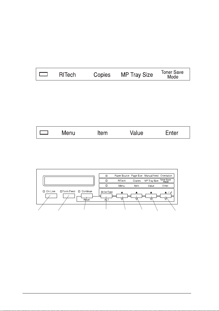
Buttons
On Line EnterSelecType
Feed
Continue
(Reset)
(ALT)
Menu Item ValueForm
2-4
On Line
Control Panel
Switches the printer between on-line
and off-line status.
Page 45

SelecType
(ALT)
Selects a OneTouch mode or
SelecType mode. Press this button
once to enter OneTouch mode 1.
Press this button again to enter
OneTouch mode 2. Press this button
once more to enter SelecType mode.
Pressing this button while in
SelecType mode returns the printer
to on-line status. See Chapter 4,
“SelecType” for more information.
2
ALT +
Menu,
Item,
Value, or
Enter
Menu
Item
Value
Advances the parameter or setting
shown to the next value in each
group. If used in combination with
ALT
the
returns the shown parameter or
setting to its previous value.
Selects the corresponding OneTouch
mode setting listed above this button
if in OneTouch mode 1 or 2, or selects
the SelecType menu if in Selec Type
mode. Press this button when the
printer is on line to enter Sel e cType
mode.
Selects the corresponding OneTouch
mode setting listed above this button
if in OneTouch mode 1 or 2, or selects
the func ti on available within the
current menu after entering the
SelecType mode.
Selects the corresponding OneTouch
mode option listed above t his button
if in OneTouch mode 1 or 2, or selects
the parameter available within the
current i tem, after ente ring the
SelecType mode menu.
button in SelecType mode, it
Control Panel
2-5
Page 46

Enter
Selects the corresponding OneTouch
mode option listed above this button
if in OneTouch mode 1 or 2, or
accepts the setting currently sh own
on the display as a new set ting when
in SelecType mode. Press this button
two times when the printer is on line
to print th e status sheet.
Form Feed
Continue
Reset
(
)
When the printer is off line and data
remains i n the printer’s memory
(Form Feed light is on), prints out the
data and clears the buffer.
Enables the printer to resume
printing af te r certain main te nancerequired conditions or errors have
been cleared. If the Continue light is
flashing, read the status or error
message on the display and correct
the problem as described in “Status
and Error Messages” on p age 5-24. If
used in combination with the
button, the printer is reset.
ALT
2-6
Control Panel
Page 47

Using the OneTouch Modes
The OneTouch modes are part of the SelecType mode, but they
are more limited and easier to use. The settings you make in these
modes and SelecType are reflected in each other.
OneTouch mode 1
2
To enter OneTouch mode 1, press the
(repeatedly if necessary) until the light next to Paper Source
comes on, indicating the printer is now in OneTouch mode 1. The
current OneTouch mode 1 settings for Paper Source, Page Size,
Manual Feed, and Orientation are shown on the display in this
order.
Paper Source
Specifies whether paper feeds into the printer from the MP tray,
the optional Envelope Feeder, a standard lower paper cassette, or
from an optional lower paper cassette (if installed). If you select
Auto, the paper source containing the paper that matches the
setting in the Page Size menu will be used.
Page Size
Specifies the paper size.
Manual Feed
Turns Manual Feed on or off. For details on the Manual Feed
mode, see “Printing one sheet at a time” on page 1-12.
Orientation
SelecType
button
Specifies whether the page is printed in portrait (Port) or
landscape (Land) orientation.
Control Panel
2-7
Page 48

OneTouch mode 2
To enter OneTouch mode 2, press the
(repeatedly if necessary) until the indicator light next to RITech
comes on, indicating the printer is in OneTouch mode 2. The
current OneTouch mode 2 settings for RITech, Copies, MP Tray
Size, and Toner Save Mode are shown on the display in this order.
SelecType
button
RITech
Turns the RITech setting on or off. RITech produces smoother and
crisper lines, text and graphics. If you change this setting, you can
check the print quality with the RITech setting by printing a status
sheet from the SelecType Test Menu.
Copies
Specifies the number of copies to be printed, up to 999.
MP Tray Size
Allows you to set the paper size for the MP tray. If you use the
optional Envelope Feeder, you can set the paper size for the
Envelope Feeder, instead.
Toner Save Mode
Turns the Toner Save Mode on or off. When turned on, the printer
saves toner by substituting a gray shade for the black inside
characters. The characters are outlined in full black on the right
and lower edges
Making OneTouch settings
To make OneTouch settings, access one of the modes as described
above and press the button located under the setting you want to
change to cycle forward through the available options. You can
also cycle backward through available options by holding down
ALT (SelecType)
want to change.
2-8
Control Panel
while pressing the button under the setting you
Page 49

Chapter 3
Options
Printer Options. . . . . . . . . . . . . . . . . . . . . . . . . . . . . . . . . . . . . . . . . . . 3-2
Installing and Removing Options. . . . . . . . . . . . . . . . . . . . . . . . . . .3-3
Large Capacity Paper U nit . . . . . . . . . . . . . . . . . . . . . . . . . . . . 3-3
Duplex Unit. . . . . . . . . . . . . . . . . . . . . . . . . . . . . . . . . . . . . . . . . 3-10
Face-up Tray . . . . . . . . . . . . . . . . . . . . . . . . . . . . . . . . . . . . . . . .3-16
Envelope Feeder . . . . . . . . . . . . . . . . . . . . . . . . . . . . . . . . . . . . .3-28
Multibin Unit. . . . . . . . . . . . . . . . . . . . . . . . . . . . . . . . . . . . . . . . 3-32
Memory modules . . . . . . . . . . . . . . . . . . . . . . . . . . . . . . . . . . . . 3-47
ROM module. . . . . . . . . . . . . . . . . . . . . . . . . . . . . . . . . . . . . . . . 3-53
Optional interfaces . . . . . . . . . . . . . . . . . . . . . . . . . . . . . . . . . . .3-54
Using the Options . . . . . . . . . . . . . . . . . . . . . . . . . . . . . . . . . . . . . . . . 3-57
Large Capacity Paper U nit . . . . . . . . . . . . . . . . . . . . . . . . . . . . 3-57
Duplex Unit. . . . . . . . . . . . . . . . . . . . . . . . . . . . . . . . . . . . . . . . . 3-58
Face-up Tray . . . . . . . . . . . . . . . . . . . . . . . . . . . . . . . . . . . . . . . .3-58
Envelope Feeder . . . . . . . . . . . . . . . . . . . . . . . . . . . . . . . . . . . . .3-60
Multibin Unit. . . . . . . . . . . . . . . . . . . . . . . . . . . . . . . . . . . . . . . . 3-61
3
Opti o ns
3-1
Page 50

Printer Options
You can add to your printer’s capabi lities by install ing any of t he
following options.
❏ The Large Capacity Paper Unit (C81303✽). Fits directly
beneath th e printer and incre ases paper feeding capacity for
most sizes of paper up to A3. Supports th e following pape r
sizes.
Lower Ca ssette 3
A3, A4, Ledger, Legal, GLG, Letter, Executive
Lower Cassette 4 or 5
A4, Letter, Exective
Note:
The asterisk (✽) is a substitute for the la st digit of the product
number, which varies b y country.
❏ The Duplex Unit (C81304✽). Prints on both sides of paper.
Supports the following paper si zes.
A3, A4, Ledger, Legal, GLG, Letter, HLT, GLT, Executive, F4
❏ The Multibin Unit (C81305✽). Can be used as a mailbox,
a sorter, or a large capacity stacker. Output capacity of 1000
printed sheets. Sup p orts the following paper sizes.
A3, A4, A5, Ledger, Legal, GLG, Letter, HLT, GLT,
Executive, F4
❏ The Face-up Tray (C81306✽). Ejec ts paper with printed side
up. Output capacity of 2 0 0 printed sheets .
❏ The Envelope Feeder (C81307✽ ). E nables you to use the
envelopes listed below. This option cannot be used with the
MP tray.
Monarch, Commercial 10, DL, C5
3-2
Options
Page 51

❏ Optional interfac e cards provide a link that enables you to use
the EPL-N4000 with additional serial or parallel interfac e.
❏ Optional memory modules expand your printer’s memory.
See “Memory modules” on page 3-47.
❏ The Adobe PostScript 3 Kit (C83232✽) ROM module
generates crisp PostScript output.
Before installing an option, read the sheet packed with the option
as well as the installation instructions in this chapter.
Installing and Removing Options
To install an option to the EPL-N4000, follow the steps in this
section. Instructions on removing the options are also included.
Large Capacity Paper Unit
This section describes how to install the Large Capacity Paper
Unit.
3
Installing the Large Capacity Paper Unit
Before installing
1. Turn off the printer.
2. Unplug the printer’s po wer cord from the electrical outlet.
3. Remo ve all interface cables from the interface connectors.
Opti o ns
3-3
Page 52

4.Open the box with the Large Capacity Paper Unit. Cut the
tape that holds the cardboard inserts.
cut here
5.Remove the inserts and all other protective materials inside
the box. Make sure the contents of the package match the
items on the included document.
Note:
Remove the packaging materials from the unit and store them for
future use.
Installing
1.Carefully lift the Large Capacity Paper Unit out of the box
with two or more people, and place it near the printe r.
3-4
Options
Page 53

2. Lock the casters at the b o ttom of the unit by pushing their
levers down.
3. At the back of the unit, push the power cable into the slot.
-
3
Opti o ns
3-5
Page 54

4. Carefully lift the printer with two or more people.
Caution:
c
❏ The printe r weighs abo ut 50 kg (110.2 lb); al ways lift it
with two or more people.
❏ Grasp the printer at the locations indicated below.
left side
5. Align each of the printer’s corners with those of the unit, then
lower the printer until it rests securel y on the unit.
right side
3-6
Options
Page 55

6. Make sure all corners of the printer fit firmly onto the unit.
After installing
1. Pull out lower cassette 2 as far as it will go. Then lift it up
slightly, and completely remove it.
3
2. Pull out lower cassette 3. Take out and open the included
package of metal fittings and screws.
Opti o ns
3-7
Page 56

3. Attach the two metal fittings with the screws as shown below.
Note that the shapes of the two fittings are differ ent.
4. Push cassette 3 back into the unit, then replace cassette 2.
5. Pull out casset te 4 and remove the protect ive materials insi de.
3-8
Options
Page 57

6. Pull out lower cassette 5 and remove the protective materials
inside. Be sure to open the inside cover and remove the
protectiv e insert.
7. Plug th e ca ble from the Large Capacity P aper Unit into the
appropri ate connector at the back of the printer .
3
8. Reconnect any interface cables you removed.
9. Make sure the printer i s turned off. Pl ug its power cord into
an electrical outlet.
10. Turn on th e printer.
Opti o ns
3-9
Page 58

To confirm that the Large Capacity Paper Unit is installed
correctly, prin t a status she et. If lower cassettes 3, 4, an d 5 are not
listed on the status sheet, make sure the cable connecting the
Large Cap acity Paper Unit to the printer is connec ted securely.
Duplex Unit
This unit allows you to prin t on both sides of paper automatically.
To install the unit, follow the instructions below.
Installing the Duplex Unit
Before in st alling
1. Turn o ff the printer.
2. Unplug the printer’s po wer cord from the electrical o utlet.
3. Remo ve all interface cables from the interface co nnectors.
4. Unpack the Duplex Unit and remove all protect ive material s.
Cauti o n:
c
Open the inner tray and remove the protective insert; otherwise,
the printer will not work properly.
3-10
Options
Page 59

Installing
1. Lift t he Duple x Un it wi th bot h hands , and fa ce the le ft si de of
the printe r.
2. Lower the unit to insert the two matching hooks into the slots
in the MP tray’s holder. Attach the hooks to the corresponding
mounting rods until you hear a click.
3. Attac h the second hook on the right side to the other rod.
3
Options
3-11
Page 60

4. Grasp the strap on the left side of the unit and insert the hook
at the end of the strap into the printer’s slot as shown below.
5. Close the Duplex Unit until it clicks.
3-12
Options
Page 61

6. After removing the pro tective cover fro m the cord, pl ug the
cord of the Duplex Unit into the appropriate connector at the
back of the pri nter.
After installing
1. Reconnect any interface cables you removed.
2. Make sure the printer is turned off. Plug the power cord into
an electrical outlet.
3
3. Turn on the printer.
To confirm that the Duplex Unit is installed correctly, print a
status sheet. If the unit is n ot listed on the stat us sheet, make sure
the cable connecting the Duplex Unit to the printer is connected
securely .
Removing th e Duplex Unit
To remov e the Duplex Unit, follow the instructi ons below.
Before removing
1. Turn off the printer.
Options
3-13
Page 62

2. Unplug the printer’s power cord from the electrical o utlet.
3. Remo ve all interface cables from the interface co nnectors.
Removing
1. Unplu g the cord of Duplex Unit fro m its connector.
2. Open the unit’s DM cover by pulling up its lever.
3-14
Options
Page 63

3. After completely opening the cover, lift it up slightly.
4. Unhook the hook at the end of the strap and fold it into the
Duplex Unit.
5. While lifting t he unit, unh ook the upper rig ht hook as shown
below.
3
Options
3-15
Page 64

6. Lift up the Duplex Unit with both hands.
After removing
1. Reconnect any interface cables you removed.
2. Make sure the printer is turned off. Plug the power cord into
an electrical outlet.
3. Turn on the printer.
Face-up Tray
Installation and removal procedures differ depending on whether
the optional Duplex Unit is installed.
Installing the Face-up Tray (without the D uplex Unit installed)
Follow the instructions below if you will not install the optional
Duplex Unit on your printer.
3-16
Options
Page 65

Before installing
1. Turn off the printer.
2. Unplug the printer’s po wer cord from the electrical outlet.
3. Remo ve all interface cables from the interface connectors.
4. Unpack the Face-up Tray and remove all protective materials.
Make sure the contents of the package match the items on the
included sheet.
Installing
1. Attach the metal bar with the static barrier shown below to
the printe r.
3
Options
3-17
Page 66

2. Insert and tighten the two finger screws include d with the
Face-up Tray as shown below.
3. Attach the frame to the tray with the two remai ning screws.
3-18
Options
Page 67

4. Hook the top edge of the Face-up Tray around the metal bar
to attach the tray to the printer.
5. Lower the Face-up Tray.
3
Options
3-19
Page 68

After installing
1. Reconnect any interface cables you removed.
2. Make sure the printer is turned off. Plug the power cord into
an electrical outlet.
3. Turn on the printer.
4. On the control panel’s Setup Menu, set Face-up Enable to
On. See “Using SelecType” on page 4-3.
To confirm that the Face-up Tray is installed correctly, print a
status sheet. If the tray is not listed on the st atus sheet, try
reinstalling it.
Note:
When replacing the imaging cartridge or clearing a paper jam, make sure
to temporarily remove the Fac e -up Tray before opening cover A.
To temporarily remove the Face-up Tray, tilt it upward and lift up.
3-20
Options
Page 69

Installing the Face-u p Tr ay (wit h the Duplex Unit installed)
Follow the instructions below if you will install both the Face-up
Tray and the optional Duplex Unit.
Before installing
1. Turn off the printer.
2. Unplug the printer’s po wer cord from the electrical outlet.
3. Remo ve all interface cables from the interface connectors.
4. Unpack the Face-up Tray and remove all protective materials.
Make sure the contents of the package match the items on the
included sheet.
Installing
1. Push the plate on the optional Duplex Unit in six locations to
detach it. Then remove the plate.
3
Options
3-21
Page 70

2. Attach the cover to the printer using the two finge r screws
included wi th the Face-up Tray.
3. Holding the hook as shown below, attach it t o the printer by
sliding it into the slot.
3-22
Options
Page 71

4. To attach the tray, hook the slots on both sid es of the Face-up
Tray to the corresponding pegs.
5. Lower the Face-up Tray.
3
After installing
1. Reconnect any interface cables you removed.
2. Make sure the printer is turned off. Plug the power cord into
an electrical outlet.
3. Turn on the printer.
4. On the control panel’s S etup Menu, s et Face-up Enable to
On. See “Using SelecType” on page 4-3.
Options
3-23
Page 72
To confirm that the Face-up Tray is installed correctly, print a
status sheet. If the tray is not listed on the st atus sheet, try
reinstalling it.
Note:
You can open the DM cover without detaching the Face-up Tray. The
tray remains angled to hold printed sh eets.
Removing the Face-up Tray (without the Duplex Unit installed)
To remove the Face-up Tray completely from the printer, follow
the instructions be lo w.
Before removing
1. Turn o ff the printer.
2. Unplug the printer’s po wer cord from the electrical o utlet.
3. Remo ve all interface cables from the interface co nnectors.
3-24
Options
Page 73

Removing
1. Unhook the Face-up Tray by tilting it upward and lifting up
slightly. Then pull it away from the printer.
2. Loosen and remove the two screws as shown below.
3
Options
3-25
Page 74

3. Remove the metal bar from the printer.
After removing
1. Reconnect any interface cables you removed.
2. Make sure the printer is off. Plug the powe r cord into an
electrical outlet.
3. Turn on the printer.
Make sure to save all parts for future use.
Removing the Fa ce-up Tray (with the Duplex U nit inst alled)
To remove the Face-up Tray completely from the printer, follow
the instructions be lo w.
Before removing
1. Turn o ff the printer.
2. Unplug the printer’s po wer cord from the electrical o utlet.
3. Remo ve all interface cables from the interface co nnectors.
3-26
Options
Page 75

Removing
1. Turn the Face-up Tray upward and lift it up.
2. Detach the hook from the cover.
3
Options
3-27
Page 76

3. Loosen a nd remove the two screws to detach the cover.
After removing
1. Reconnect any interface cables you removed.
2. Make sure the printer is turned off. Plug the power cord into
an electrical outlet.
3. Turn on the printer.
Make sure to save all parts for future use.
Envelope Feeder
To install the Envelope Feeder, you must remove the MP tray first.
3-28
Options
Page 77
Installing the Envelo pe Feeder
Follow the instructions below.
Before installing
1. Turn off the printer.
2. Unplug the printer’s po wer cord from the electrical outlet.
3. Remo ve all interface cables from the interface connectors.
4. Unpack the Envelope Feeder and remove all protective
materials.
Installing
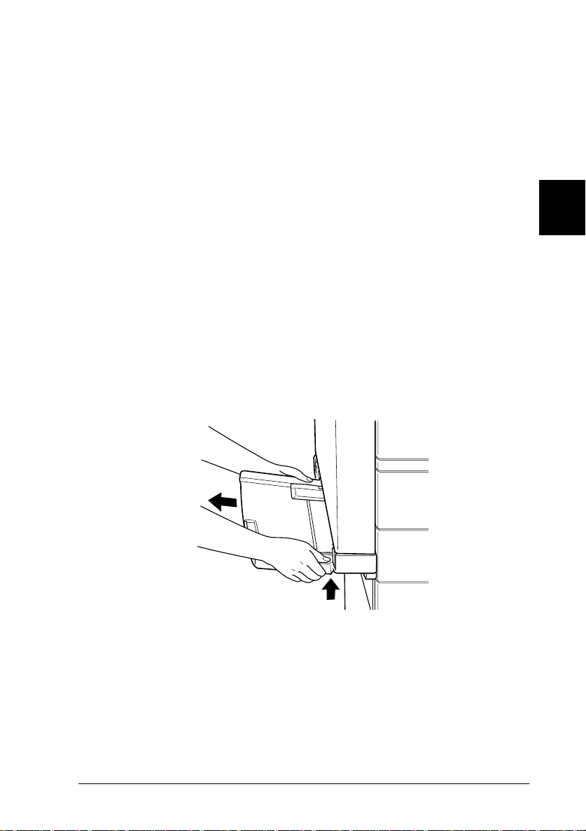
1. Remove the MP tray by lifting it slightly and pulling it out
toward you. The MP tray does not detach easily; use sufficient
force to pu ll it away from the printer.
3
2. After unpacking the Envelope Feeder, hold it horizontally
with both hands.
Options
3-29
Page 78
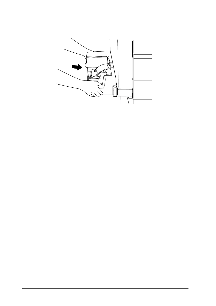
3. Push it straight into the prin ter until it clicks firmly in to place.
After installing
1. Reconnect any interface cables you removed.
2. Make sure the printer is turned off. Plug the power cord into
an electrical outlet.
3. Turn on the printer.
To confirm that the Envelope Feeder is installed correctly, print a
status sheet. If the feeder is not listed on the status sheet, try
reinstalling it.
Removing the Enve lope Feeder
Note:
❏
When replacing the imaging cartridge or clearing a paper jam, make
sure to temporarily remove the Envelope Feeder before opening cover
A.
❏
Always have either the Envelope Feeder or the MP tray installed. If
neither of them are installed, the message
the control panel.
To remove the Envelope Feeder, follow the instructions below.
3-30
Options
Set MP Tray
appears on
Page 79
Before removing
1. Turn off the printer.
2. Unplug the printer’s po wer cord from the electrical outlet.
3. Remo ve all interface cables from the interface connectors.
Removing
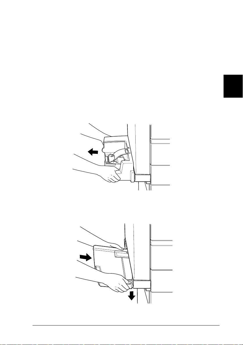
1. Slightly lift the E nvelope Feeder and pull it out to ward y ou.
The Envelope Feeder does not detach easily; use sufficient
force to pu ll it away from the printer.
2. Push the MP tray straight into the printer until it clicks firmly
into place.
3
Options
3-31
Page 80

After removing
1. Reconnect any interface cables you removed.
2. Make sure the printer is turned off. Plug the power cord into
the printer, then into an electrical outlet.
3. Turn on the printer.
Multibin Unit
This unit can be used as a mailbox, a sorter, a multiple sorter, or
a large capacity stacker. To install, foll ow the instruc ti ons below.
Installing the Multib in Unit
Before in st alling
1. Turn o ff the printer.
2. Unplug the printer’s po wer cord from the electrical o utlet.
3. Remo ve all interface cables from the interface co nnectors.
4. Open th e bo x from the top. W ithout removi ng the Mul ti b i n
Unit, take out all other parts and protective materials from the
box.
3-32
Options
Page 81

Installing th e si de b ra cke ts
1. Open th e box inside and take out the bracket that fits on the
right side of the Large Capacity Paper Unit (see illustration).
2. Align the two pins on the bracket with the holes on the righ t
side of the printer. Insert the pins into the Large Capacity
Paper Unit, then lower the bracket until it is firmly attached.
3
3. Insert one of the included screws shown above into the hole
in the brac ket and tighten.
4. Remove the protective cover from the remaining bracket, then
repeat steps 2 and 3 to install the bracket to the left side of the
printer.
Options
3-33
Page 82

Installin g th e to p br a cket
1. Remove the protectiv e cover from the to p bracket.
2. With the orientation shown below, insert the two legs of the
top bracket into the side brackets and push down evenly on
both side s until the bracke t clicks into pla ce .
Keep this pole on the
side with the MP tray,
opposite from the
stopper
stopper.
MP tray
3. Remove the protectiv e material from the top pin.
3-34
Options
Page 83

Installing the Multibin Unit
1. Pull away the four clips from the box, then lift the box up.
2. Lift the Multibin Unit out of the box and place it on the floor
as shown below. Remov e the protective ma terial just before
installing the unit to t he printer.
3
Options
3-35
Page 84

3. Grasp the Multibin Unit at the solid areas shown below.
arm
top view
grip
Caution:
c
4. Lift the unit a nd align th e pole on the Multibin Unit with t he
pole of the top bracket as shown below.
Do not support the unit at th e areas marked with X above
(the latch on cover D and the end of the arm). Attempting so
can damage the cover or the unit.
3-36
Options
Page 85

5. Lower the Multibin Unit until the plat e on the Multib in Unit
is slightly higher than the top of the pin o n the top bracket.
6. Push the Multibin Unit horizontally into the pole on the top
bracket as shown below.
3
Options
3-37
Page 86

7. Lower the Multibin Unit until the pin fits completely into the
hole on the plate.
8. Make sure the bottom part of the unit is set above and parallel
with the p ri nte r.
Locking the Multibin Unit
1. Remove the protective tape as shown below.
3-38
Options
Page 87

2. Open cover D an d d etach t he grip f r om the i nsi de. To d e tach
the grip, push the button near the side of the grip, lower the
grip a little, then pull it away from the Multibin Unit.
3. Attach the grip on the opposite side of Multibin Unit. To do
this, align the grip’s metal bracket with the slot in the top
bracket, th e n i nsert the grip into the hollow on the side of
Multibin Unit. Push in until it clicks.
3
Note:
Be sure to lock the Multi bin U nit by attaching the handle as
explained above.
Options
3-39
Page 88

After installing
1. Open cover D and r emove all protecti ve material s insi de and
outside the Multibin Unit.
2. Attach the sheet st opper by inser ting its two ends into the
holes on the top and botto m bin.
3-40
Options
Page 89

3. Plug th e cord of the Multibin Unit into the a ppropriate
connector on the back of the printer.
4. Reconnect any interface cables you removed.
5. Make sure the printer is turned off. Plug the power cord into
an electrical outlet.
6. Turn on the printer.
To confirm that the Multibin Unit is installed correctly, print a
status sheet by pushing the
times w hile the printer is on line. If the unit is not listed on the
status sheet, make sure the cable connecting the Multibin Unit to
the print er is connec te d securely.
Enter
button on the control panel two
3
Removing the Multibin Unit
Follow the instructions below.
Before removing
1. Turn off the printer.
2. Unplug the printer’s po wer cord from the electrical outlet.
Options
3-41
Page 90

3. Remo ve all interface cables from the interface co nnectors.
4. Unplug the cord of the Multibin Unit from its connector on
the back of the printer.
5. Detach the sheet stopper by pulling its ends out of the top and
bottom bins.
3-42
Options
Page 91
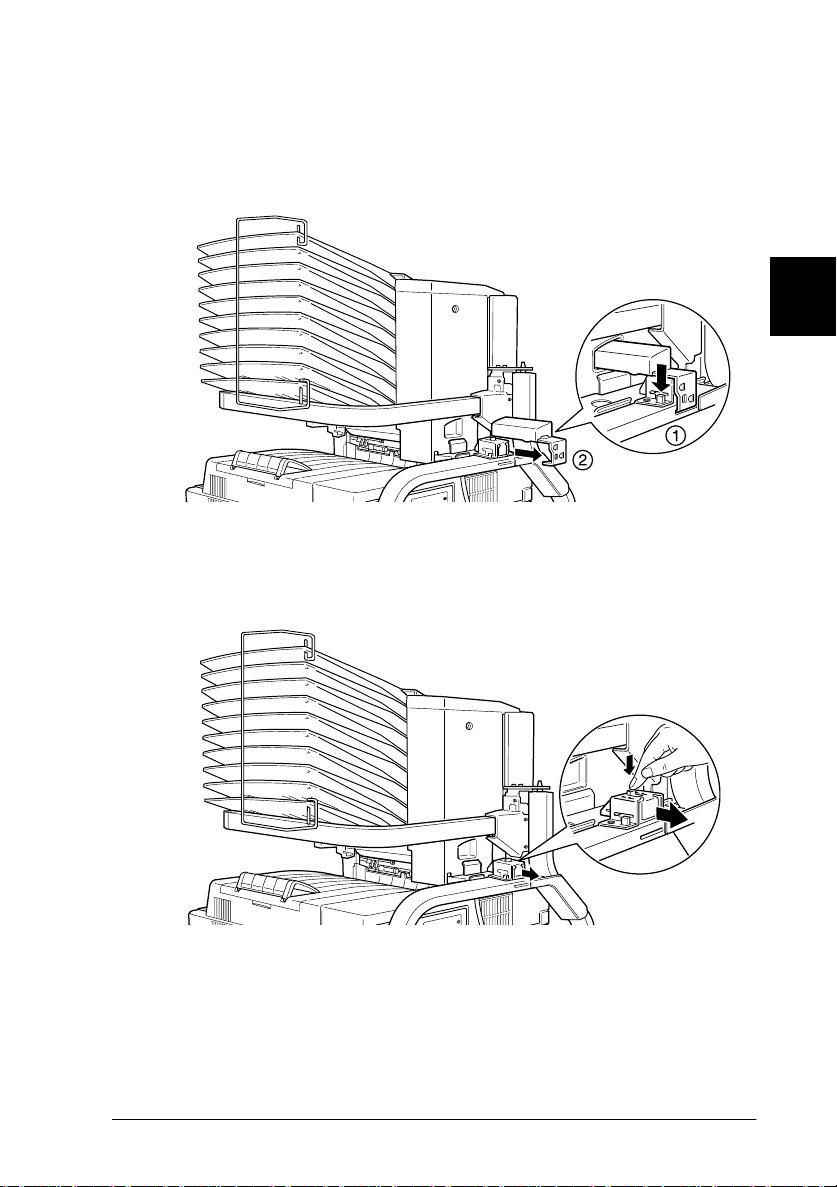
Unlocking the Multibin Unit
1. Detach the grip at the back by pushing the button and pulling
out the grip, as shown be low.
2. Push the tab of the lock dow n and pul l it away f rom the unit
until it unlocks.
3
Options
3-43
Page 92

3. Open cover D and attach the grip to the inside of the unit. To
do so, position the grip as shown below, push it in and lift it
up slightly until it clicks.
Removing the Multibin Unit
1. Grasp the Multibin Unit at the solid areas below.
arm
3-44
c
Options
top view
grip
Caution:
Do not support the unit at th e areas above marked with X
(the latch on cover D and the end of the arm). Doing so can
damage the cover or the uni t.
Page 93
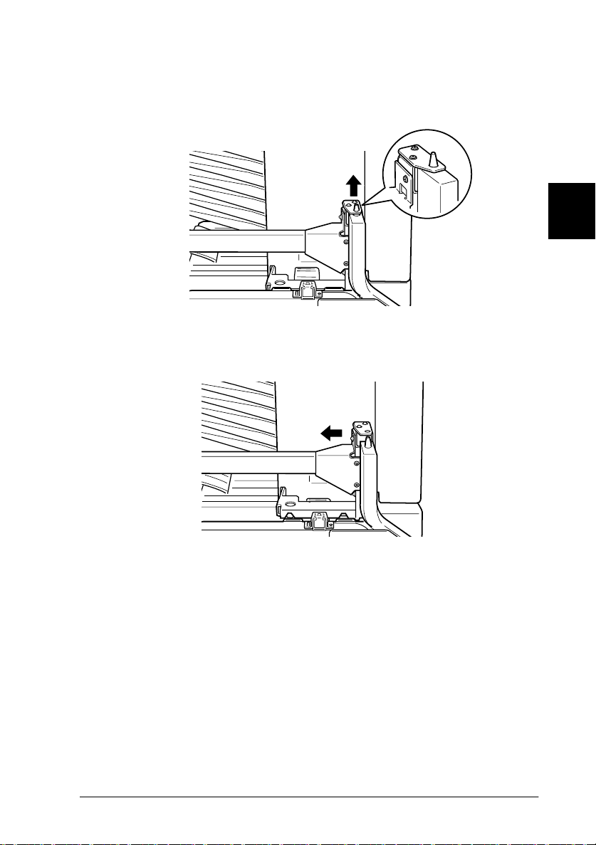
2. Lift the unit up, completely away from the pin on the top
bracket.
3. Move the unit away from the pole on the top bracket.
3
Options
3-45
Page 94

Caution:
c
4. Push in the plastic tabs on the inside of both side brackets, and
lift up the top bracket.
If you place the Multibin Unit temporarily on a desk or floor,
always keep the bins p oint ing up as shown below; doing
otherwise can damag e the unit.
3-46
Options
Page 95

After removing
1. Reconnect any interface cables you removed.
2. Make sure the printer is turned off. Plug the power cord into
an electrical outlet.
3. Turn on the printer.
Memory modules
By installing a memory module in both open slots, you can
increase printer memory up to 2 56 MB. You may want to add
memory if you are having d ifficulty printing complex, graphi csintensive pages, using the Multibin Unit wi th the Duplex Unit, or
if you regularly use numerous downloaded fonts.
You can purchase memory modules from various vendors. Be
sure the memory module you purcha se meets the following
requirements.
❏ Synchronous Dynamic RAM Double In-line Memory Module
(SD RAM DIMM)
3
❏ 168-pin type, 64 bit, with SPD
❏ Capacity of 16, 32, 64, or 128 MB
❏ Access speed of 66.66 MHz or higher (15 ns or less)
❏ Height of less than 40 mm
Options
3-47
Page 96
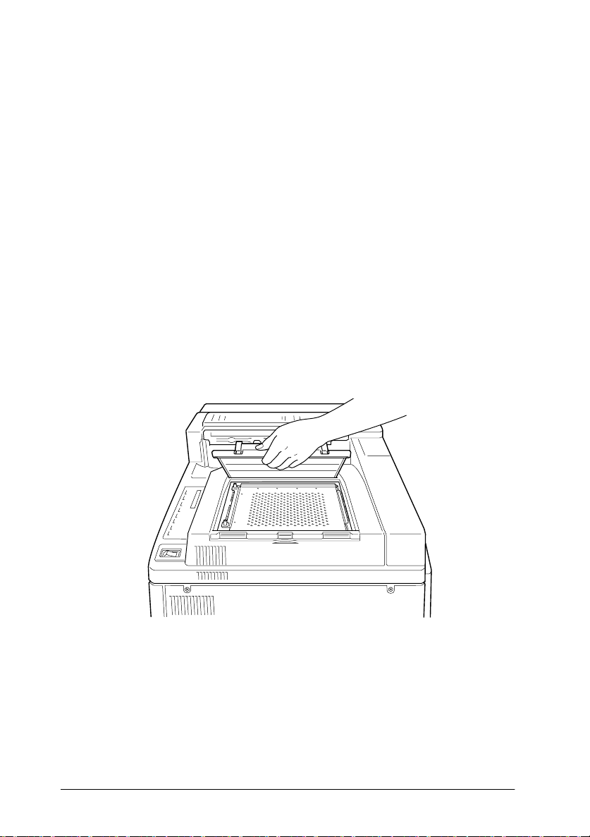
Installing a memory mo dule
Before in st alling
1. Turn o ff the printer.
Warning:
w
2. Unplug the printer’s power cord from the electrical o utlet.
3. Remo ve all interface cables from the interface co nnectors.
4. Remove the Multibin Unit if i t is install ed. See “Removing the
Multibin Unit” on page 3-41.
5. Open the top cover of the face-down tray with your fingers.
To avoid electrical shock, do not attempt to install a memory
module unless the pr inter is turned off.
3-48
Options
Page 97

6. Loosen the two retaining screws and remove the plate.
Note:
To avoid loosing the retaining screws, do not remove them
completely fro m the plate.
Warning:
w
Installing
1. Slots for memory modules are located as shown below.
Avoid touching electrical components that are exposed after
you remove the shield cover. They may be very hot if the
printer has been in use.
3
SLOT S0
SLOT S1
SLOT S2
Options
3-49
Page 98

2. Pull the clips on each side of SLOT S1 outward.
3. Hold the memory module above SLOT S 1 with t he followi ng
orientation, th en push it down into SLOT S1. Do not apply too
much force.
4. At the ri ght side, push the bottom co rner of the m emory
module until the clip comes up.
5. With the other hand, push the bottom corner of the me mory
module until the clip comes up to retain the memory module
securely.
6. To install another memory module in SLOT S2, r epeat steps
2 through 5.
3-50
Options
Page 99

After installing
1. Replace the plate to its original position. Place t he two outside
tabs of the plate under the e dge of the opening with the inside
tabs on top of the edge.
2. Push the plate down into place.
3
3. Tighten the two screws that you loosened earlier.
4. Gently replace the top cover until it c licks shut.
To confirm that the memory module is i nstalled correctly, pr int a
status sheet.
Options
3-51
Page 100

Removing a memory module
1. Follow the step s in “Before installing” on page 3-48 t o acces s
the memory slot.
2. Pull the c lips on each side of SLOT S1 or S2 outward to release
the memory module.
Note:
SLOT S0 should al ways have a memory module installed.
3. Grasp both s ides of the memory m odule and p ull t he module
out.
4. Follow steps 1 through 4 in “Af ter install ing” on page 3-5 1 to
complete the procedure.
3-52
Options
 Loading...