

Page 1
®
SERVICE MANUAL
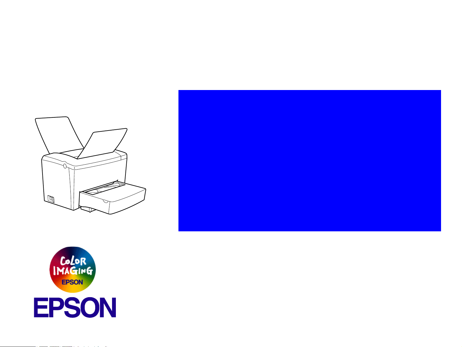
Monochrome Page Printer
EPSON EPL-5900 / EPL-5900L
SEPG01005
Page 2

Notice
All rights reserved. No part of this manual may be reproduced, stored in a retrieval system, or transmitted in any form or by any means electronic, mechanical,
photocopying, or otherwise, without the prior written permission of SEIKO EPSON CORPORATION.
All effort have been made to ensure the accuracy of the contents of this manual. However, should any errors be detected, SEIKO EPSON would greatly
appreciate being informed of them.
The contents of this manual are subject to change without notice.
All effort have been made to ensure the accuracy of the contents of this manual. However, should any errors be detected, SEIKO EPSON would greatly
appreciate being informed of them.
The above not withstanding SEIKO EPSON CORPORATION can assume no responsibility for any errors in this manual or the consequences thereof.
EPSON is a registered trademark of SEIKO EPSON CORPORATION.
General Notice: Other product names used herein are for identification purpose only and may be trademarks or registered trademarks of their
respective owners. EPSON disclaims any and all rights in those marks.
Copyright © 2001 SEIKO EPSON CORPORATION.
Imaging & Information Product Division
TPCS Quality Assurance Department
Page 3

PRECAUTIONS
Precautionary notations throughout the text are categorized relative to 1)Personal injury and 2) damage to equipment.
DANGER Signals a precaution which, if ignored, could result in serious or fatal personal injury. Great caution should be exercised in performing procedures preceded by
DANGER Headings.
WARNING Signals a precaution which, if ignored, could result in damage to equipment.
The precautionary measures itemized below should always be observed when performing repair/maintenance procedures.
DANGER
1. ALWAYS DISCONNECT THE PRODUCT FROM THE POWER SOURCE AND PERIPHERAL DEVICES PERFORMING ANY MAINTENANCE OR REPAIR PROCEDURES.
2. NO WORK SHOULD BE PERFORMED ON THE UNIT BY PERSONS UNFAMILIAR WITH BASIC SAFETY MEASURES AS DICTATED FOR ALL ELECTRONICS
TECHNICIANS IN THEIR LINE OF WORK.
3. WHEN PERFORMING TESTING AS DICTATED WITHIN THIS MANUAL, DO NOT CONNECT THE UNIT TO A POWER SOURCE UNTIL INSTRUCTED TO DO SO. WHEN
THE POWER SUPPLY CABLE MUST BE CONNECTED, USE EXTREME CAUTION IN WORKING ON POWER SUPPLY AND OTHER ELECTRONIC COMPONENTS.
4. WHEN DISASSEMBLING OR ASSEMBLING A PRODUCT, MAKE SURE TO WEAR GLOVES TO AVOID INJURIER FROM METAL PARTS WITH SHARP EDGES.
WARNING
1. REPAIRS ON EPSON PRODUCT SHOULD BE PERFORMED ONLY BY AN EPSON CERTIFIED REPAIR TECHNICIAN.
2. MAKE CERTAIN THAT THE SOURCE VOLTAGES IS THE SAME AS THE RATED VOLTAGE, LISTED ON THE SERIAL NUMBER/RATING PLATE. IF THE EPSON
PRODUCT HAS A PRIMARY AC RATING DIFFERENT FROM AVAILABLE POWER SOURCE, DO NOT CONNECT IT TO THE POWER SOURCE.
3. ALWAYS VERIFY THAT THE EPSON PRODUCT HAS BEEN DISCONNECTED FROM THE POWER SOURCE BEFORE REMOVING OR REPLACING PRINTED CIRCUIT
BOARDS AND/OR INDIVIDUAL CHIPS.
4. IN ORDER TO PROTECT SENSITIVE MICROPROCESSORS AND CIRCUITRY, USE STATIC DISCHARGE EQUIPMENT, SUCH AS ANTI-STATIC WRIST STRAPS, WHEN
ACCESSING INTERNAL COMPONENTS.
5. DO NOT REPLACE IMPERFECTLY FUNCTIONING COMPONENTS WITH COMPONENTS WHICH ARE NOT MANUFACTURED BY EPSON. IF SECOND SOURCE IC OR
OTHER COMPONENTS WHICH HAVE NOT BEEN APPROVED ARE USED, THEY COULD CAUSE DAMAGE TO THE EPSON PRODUCT, OR COULD VOID THE
WARRANTY OFFERED BY EPSON.
Page 4

About This Manual
This manual describes basic functions, theory of electrical and mechanical operations, maintenance and repair procedures of the printer. The instructions and procedures included
herein are intended for the experienced repair technicians, and attention should be given to the precautions on the preceding page.
Manual Configuration
This manual consists of six chapters and Appendix.
CHAPTER 1.PRODUCT DESCRIPTIONS
Provides a general overview and specifications of the product.
CHAPTER 2.OPERATING PRINCIPLES
Describes the theory of electrical and mechanical operations of
the product.
CHAPTER 3.TROUBLESHOOTING
Describes the step-by-step procedures for the troubleshooting.
CHAPTER 4.DISASSEMBLY / ASSEMBLY
Describes the step-by-step procedures for disassembling and
assembling the product.
CHAPTER 5.ADJUSTMENT
Provides Epson-approved methods for adjustment.
CHAPTER 6.MAINTENANCE
Provides preventive maintenance procedures and the lists of
Epson-approved lubricants and adhesives required for servicing
the product.
APPENDIX Provides the following additional information for reference:
• Connector pin assignments
• Electric circuit boards components layout
• Electrical circuit boards schematics
• Exploded diagram & Parts List
Symbols Used in this Manual
Various symbols are used throughout this manual either to provide additional
information on a specific topic or to warn of possible danger present during a
procedure or an action. Be aware of all symbols when they are used, and
always read NOTE, CAUTION, or WARNING messages.
A D J U S T M E N T
R E Q U I R E D
C A U T I O N
C H E C K
P O I N T
W A R N I N G
Indicates an operating or maintenance procedure, practice or
condition that is necessary to keep the product’s quality.
Indicates an operating or maintenance procedure, practice, or
condition that, if not strictly observed, could result in damage to,
or destruction of, equipment.
May indicate an operating or maintenance procedure, practice or
condition that is necessary to accomplish a task efficiently. It may
also provide additional information that is related to a specific
subject, or comment on the results achieved through a previous
action.
Indicates an operating or maintenance procedure, practice or
condition that, if not strictly observed, could result in injury or loss
of life.
Page 5
Safety Precautions for Inspection and Service
When performing inspection and service procedures, observe the
following precautions to prevent accidents and ensure utmost safety.
* Depending on the model, some of the precautions given in the
following do not apply.
Different markings are used to denote specific meanings as detailed
below.
W A R N I N G
C A U T I O N
The following graphic symbols are used to give instructions that need to
be observed.
fIndicates a potentially hazardous situation which, if not
avoided, could result in death or serious injury.
Indicates a potentially hazardous situation which, if not
avoided, may result in minor or moderate injury. It may
also be used to alert against unsafe practices.
Used to call the service technician's attention to what is
graphically represented inside the marking (including a
warning).
Used to prohibit the service technician's from doing what is
graphically represented inside the marking.
Used to instruct the service technician's to do what is
graphically represented inside the marking.
W A R N I N G
WARNING
1.Always observe precautions.
Parts requiring special attention in this product will include a
label containing the mark shown on the left plus
precautionary notes. Be sure to observe the precautions.
Be sure to observe the “Safety Information” given in the
Operator's Manual.
2.Before starting the procedures, be sure to unplug the power
cord.
This product contains a high-voltage unit and a circuit with a
large current capacity that may cause an electric shock or
burn.
The product also contains parts that can jerk suddenly and
cause injury.
If this product uses a laser, laser beam leakage may cause
eye damage or blindness.
3.Use the specified parts.
For replacement parts, always use the genuine parts
specified in the manufacturer's parts manual. Installing a
wrong or unauthorized part could cause dielectric
breakdown, overload, or undermine safety devices resulting
in possible electric shock or fire.
Replace a blown electrical fuse or thermal fuse with its
corresponding genuine part specified in the manufacturer's
parts manual. Installing a fuse of a different make or rating
could lead to a possible fire. If a thermal fuse blows
frequently, the temperature control system may have a
problem and action must be taken to eliminate the cause of
the problem.
Page 6
4.Handle the power cord with care and never use a multiple outlet.
9.Do not remodel the product.
Do not break, crush or otherwise damage the power cord.
Placing a heavy object on the power cord, or pulling or
bending it may damage it, resulting in a possible fire or
electric shock.
Do not use a multiple outlet to which any other appliance or
machine is connected.
Be sure the power outlet meets or exceeds the specified
capacity.
5.Be careful with the high-voltage parts.
A part marked with the symbol shown on the left carries a
high voltage. Touching it could result in an electric shock or
burn. Be sure to unplug the power cord before servicing this
part or the parts near it.
6.Do not work with wet hands.
Do not unplug or plug in the power cord, or perform any kind
of service or inspection with wet hands. Doing so could
result in an electric shock.
7.Do not touch a high-temperature part.
A part marked with the symbol shown on the left and other
parts such as the exposure lamp and fusing roller can be
very hot while the machine is energized. Touching them
may result in a burn.
Wait until these parts have cooled down before replacing
them or any surrounding parts.
Modifying this product in a manner not authorized by the
manufacturer may result in a fire or electric shock. If this
product uses a laser, laser beam leakage may cause eye
damage or blindness.
10.Restore all parts and harnesses to their original positions.
To promote safety and prevent product damage, make sure
the harnesses are returned to their original positions and
properly secured in their clamps and saddles in order to
avoid hot parts, high-voltage parts, sharp edges, or being
crushed.
To promote safety, make sure that all tubing and other
insulating materials are returned to their original positions.
Make sure that floating components mounted on the circuit
boards are at their correct distance and position off the
boards.
8.Maintain a grounded connection at all times.
(This item may not apply in the USA.)
Be sure to connect the ground wire to the ground terminal
even when performing an inspection or repair. Without
proper grounding, electrical leakage could result in an
electric shock or fire.
Never connect the ground wire to a gas pipe, water pipe,
telephone ground wire, or a lightning conductor.
Page 7
C A U T I O N
CAUTION
1.Precautions for Service Jobs
A toothed washer and spring washer, if used originally,
must be reinstalled. Omitting them may result in contact
failure which could cause an electric shock or fire.
When reassembling parts, make sure that the correct
screws (size, type) are used in the correct places. Using the
wrong screw could lead to stripped threads, poorly secured
parts, poor insulating or grounding, and result in a
malfunction, electric shock or injury.
Take great care to avoid personal injury from possible burrs
and sharp edges on the parts, frames and chassis of the
product.
When moving the product or removing an option, use care
not to injure your back or allow your hands to be caught in
mechanisms.
2.Precautions for Servicing with Covers and Parts Removed
Wherever feasible, keep all parts and covers mounted when
energizing the product.
If energizing the product with a cover removed is absolutely
unavoidable, do not touch any exposed live parts and use
care not to allow your clothing to be caught in the moving
parts. Never leave a product in this condition unattended.
Never place disassembled parts or a container of liquid on
the product. Parts falling into, or the liquid spilling inside, the
mechanism could result in an electric shock or fire.
Never use a flammable spray near the product. This could
result in a fire.
Make sure the power cord is unplugged before removing or
installing circuit boards or plugging in or unplugging
connectors.
Always use the interlock switch actuating jig to actuate an
interlock switch when a cover is opened or removed. The
use of folded paper or some other object may damage the
interlock switch mechanism, possibly resulting in an electric
shock, injury or blindness.
3.Precautions for the Working Environment
The product must be placed on a flat, level surface that is
stable and secure.
Never place this product or its parts on an unsteady or tilting
workbench when servicing.
Provide good ventilation at regular intervals if a service job
must be done in a confined space for a long period of time.
Avoid dusty locations and places exposed to oil or steam.
Avoid working positions that may block the ventilation ports
of the product.
4.Precautions for Handling Batteries
(Lithium, Nickel-Cadmium, etc.)
Replace a rundown battery with the same type as specified
in the manufacturer's parts manual.
Before installing a new battery, make sure of the correct
polarity of the installation or the battery could burst.
Dispose of used batteries according to the local regulations.
Never dispose of them at the user's premises or attempt to
try to discharge one.
Page 8
5.Precautions for the Laser Beam
(Only for Products Employing a Laser)
Removing the cover marked with the following caution label
could lead to possible exposure to the laser beam, resulting
in eye damage or blindness. Be sure to unplug the power
cord before removing this cover.
If removing this cover while the power is ON is unavoidable,
be sure to wear protective laser goggles that meet
specifications.
Make sure that no one enters the room when the machine is
in this condition.
When handling the laser unit, observe the “Precautions for
Handling Laser Equipment.”
Other Precautions
When handling circuit boards, observe the “HANDLING of PWBs”.
The PC Drum is a very delicate component. Observe the precautions
given in “HANDLING OF THE PC DRUM” because mishandling may
result in serious image problems.
Note that replacement of a circuit board may call for readjustments or
resetting of particular items, or software installation.
Page 9

Precautions for Service
When performing inspection and service procedures, observe the
following precautions to prevent mishandling of the machine and its
parts.
All troubleshooting procedures contained herein assume that
there are no breaks in the harnesses and cords and all
connectors are plugged into the right positions.
The procedures preclude possible malfunctions due to noise
and other external causes.
* Depending on the model, some of the precautions given in the
following do not apply.
PRECAUTIONS BEFORE SERVICE
When the user is using a word processor or personal computer from
a wall outlet of the same line, take necessary steps to prevent the
circuit breaker from opening due to overloads.
Never disturb the LAN by breaking or making a network connection,
altering termination, installing or removing networking hardware or
software, or shutting down networked devices without the
knowledge and express permission of the network administrator or
the shop supervisor.
HOW TO USE THIS BOOK
DIS/REASSEMBLY, ADJUSTMENT
To reassemble the product, reverse the order of disassembly
unless otherwise specified.
TROUBLESHOOTING
PRECAUTIONS FOR SERVICE
Check the area surrounding the service site for any signs of
damage, wear or need of repair.
Keep all disassembled parts in good order and keep tools under
control so that none will be lost or damaged.
After completing a service job, perform a safety check. Make sure
that all parts, wiring and screws are returned to their original
positions.
Do not pull out the toner hopper while the toner bottle is turning.
This could result in a damaged motor or locking mechanism.
If the product is to be run with the front door open, make sure that
the toner hopper is in the locked position.
Do not use an air gun or vacuum cleaner for cleaning the ATDC
Sensor and other sensors, as they can cause electrostatic
destruction. Use a blower brush and cloth. If a unit containing these
sensors is to be cleaned, first remove the sensors from the unit.
If a component on a PWB or any other functional unit including a
motor is defective, the text only instructs you to replace the
whole PWB or functional unit and does not give troubleshooting
procedures applicable within the defective unit.
Page 10

PRECAUTIONS FOR DIS/REASSEMBLY
PRECAUTIONS FOR CIRCUIT INSPECTION
Be sure to unplug the copier from the outlet before attempting to
service the copier.
The basic rule is not to operate the copier anytime during
disassembly. If it is absolutely necessary to run the copier with its
covers removed, use care not to allow your clothing to be caught in
revolving parts such as the timing belt and gears.
Before attempting to replace parts and unplug connectors, make
sure that the power cord of the copier has been unplugged from the
wall outlet.
Be sure to use the Interlock Switch Actuating Jig whenever it is
necessary to actuate the Interlock Switch with the covers left open
or removed.
While the product is energized, do not unplug or plug connectors
into the circuit boards or harnesses.
Never use flammable sprays near the copier.
A used battery should be disposed of according to the local
regulations and never be discarded casually or left unattended at
the user's premises.
When reassembling parts, make sure that the correct screws (size,
type) and toothed washer are used in the correct places.
Never create a closed circuit across connector pins except those
specified in the text and on the printed circuit.
When creating a closed circuit and measuring a voltage across
connector pins specified in the text, be sure to use the GND wire.
HANDLING OF PWBS
During Transportation/Storage:
During transportation or when in storage, new P.W. Boards must
not be indiscriminately removed from their protective conductive
bags.
Do not store or place P.W. Boards in a location exposed to
direct sunlight and high temperature.
When it becomes absolutely necessary to remove a Board from
its conductive bag or case, always place it on its conductive mat
in an area as free as possible from static electricity.
Do not touch the pins of the ICs with your bare hands.
Protect the PWBs from any external force so that they are not
bent or damaged.
During Inspection/Replacement:
If it becomes necessary to replace the thermal fuse or any other
fuse mounted on a board, be sure to use one of the rating marked
on the blown fuse. Always note the rating marked on the fuse, as
the rating and mounting site or number used are subject to change
without notice.
Avoid checking the IC directly with a multimeter; use connectors
on the Board.
Never create a closed circuit across IC pins with a metal tool.
Before unplugging connectors from the P.W. Boards, make sure
that the power cord has been unplugged from the outlet.
Page 11

When removing a Board from its conductive bag or conductive
case, do not touch the pins of the ICs or the printed pattern.
Place it in position by holding only the edges of the Board.
When touching the PWB, wear a wrist strap and connect its cord
to a securely grounded place whenever possible. If you cannot
wear a wrist strap, touch a metal part to discharge static
electricity before touching the PWB.
HANDLING OF THE PC DRUM
* Only for Products Not Employing an Imaging Cartridge.
During Transportation/Storage:
Use the specified carton whenever moving or storing the PC
Drum.
Note that replacement of a PWB may call for readjustments or
resetting of particular items.
HANDLING OF OTHER PARTS
The magnet roller generates a strong magnetic field. Do not bring it
near a watch, floppy disk, magnetic card, or CRT tube.
The storage temperature is in the range between -20°C and
+40°C.
In summer, avoid leaving the PC Drum in a car for a long time.
Handling:
Ensure that the correct PC Drum is used.
Whenever the PC Drum has been removed from the copier,
store it in its carton or protect it with a Drum Cloth.
The PC Drum exhibits greatest light fatigue after being exposed
to strong light over an extended period of time. Never, therefore,
expose it to direct sunlight.
Use care not to contaminate the surface of the PC Drum with oil-
base solvent, fingerprints, and other foreign matter.
Do not scratch the surface of the PC Drum.
Do not apply chemicals to the surface of the PC Drum.
Do not attempt to wipe clean the surface of the PC Drum.
Page 12
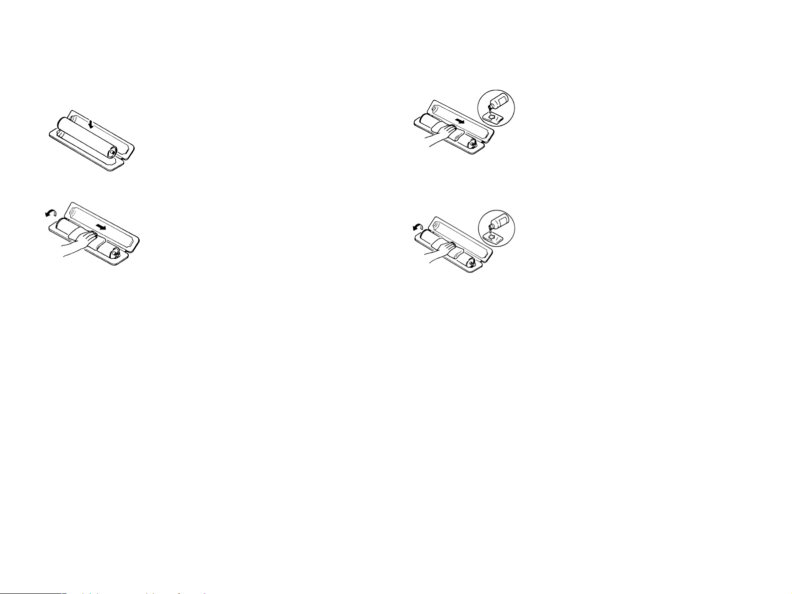
If, however, the surface is contaminated with fingerprints, clean it using
the following procedure.
1. Place the PC Drum into one half of its carton.
3. Soak a small amount of either ethyl alcohol
or isopropyl alcohol into a clean, unused
Dust-Free Cotton Pad which has been
folded over into quarters. Now, wipe the
surface of the PC Drum in one continuous
movement from its rear edge to its front
edge and off its surface one to two times.
2. Gently wipe the residual toner off the
surface of the PC Drum with a dry, DustFree Cotton Pad.
A.Turn the PC Drum so that the area of its
surface on which the line of toner left by the
Cleaning Blade is present is facing straight
up. Wipe the surface in one continuous
movement from the rear edge of the PC
Drum to the front edge and off the surface
of the PC Drum.
B. Turn the PC Drum slightly and wipe the
newly exposed surface area with a CLEAN
face of the Dust-Free Cotton Pad. Repeat
this procedure until the entire surface of the
PC Drum has been thoroughly cleaned.
*At this time, always use a CLEAN face of the dry
Dust-Free Cotton Pad until no toner is evident on
the face of the Pad after wiping.
*Never move the Pad back and forth.
4. Using the SAME face of the Pad, repeat the
procedure explained in the latter half of
step 3 until the entire surface of the PC
Drum has been wiped. Always OVERLAP
the areas when wiping. Two complete turns
of the PC Drum would be appropriate for
cleaning.
NOTE:
Even when the PC Drum is only locally dirtied, wipe the entire
surface.
Do not expose the PC Drum to direct sunlight. Clean it as
quickly as possible even under interior illumination.
If dirt remains after cleaning, repeat the entire procedure from
the beginning one more time.
Page 13

HANDLING OF THE IMAGING CARTRIDGE
* Only for Products Employing an Imaging Cartridge.
During Transportation/Storage:
The storage temperature is in the range between -20°C and
+40°C.
In summer, avoid leaving the Imaging Cartridge in a car for a
long time.
Handling:
Store the Imaging Cartridge in a place that is not exposed to
direct sunlight.
Precautionary Information on the PC Drum Inside the Imaging
Cartridge:
Use care not to contaminate the surface of the PC Drum with oil-
base solvent, fingerprints, and other foreign matter.
Do not scratch the surface of the PC Drum.
Do not attempt to wipe clean the surface of the PC Drum.
W A R N I N G
WARNING
Do not throw the toner cartridge or toner into an open
flame. The hot toner may scatter and cause burns or
other damage.
Page 14
SAFETY INFORMATION
LASER SAFETY
This is a digital machine certified as a class 1 laser product. There is no
possibility of danger from a laser, provided the machine is serviced
according to the instruction in this manual.
INTERNAL LASER RADIATION
semiconductor laser
Maximum average radiation power(*) 27.1 µW
Wavelength 770-810 nm
*:Laser Aperture of the Print Head Unit
This product employs a Class 3b laser diode that emits an invisible
laser beam. The laser diode and the scanning polygon mirror are
incorporated in the print head unit.
The print head unit is NOT A FIELD SERVICE ITEM. Therefore, the
print head unit should not be opened under any circumstances.
the U.S.A., Canada (CDRH Regulation)
This machine is certified as a Class I Laser product under
Radiation Performance Stan-dard according to the Food, Drug
and Cosmetic Act of 1990. Compliance is mandatory for Laser
products marketed in the United States and is reported to the
Center for Devices and Radiological Health (CDRH) of the U.S.
Food and Drug Administration of the U.S. Department of Health
and Human Services (DHHS). This means that the device does
not produce hazardous laser radiation.
The label shown to page 15 indicates compliance with the
CDRH regulations and must be attached to laser products
marketed in the United States.
CAUTION
Use of controls, adjustments or performance of procedures other than those
specified in this manual may result in hazardous radiation exposure.
semiconductor laser
Maximum power of the laser diode 5 mW
Wavelength 770-810 nm
Laser Aperture of the Print Head Unit
This figure shows the view inside the Top Cover with the Toner Cartridge and the Drum Cartridge removed.
All Areas
CAUTION
Use of controls, adjustments or performance of procedures other than those
specified in this manual may result in hazardous radiation exposure.
semiconductor laser
Maximum power of the laser diode 5 mW
Wavelength 770-810 nm
Page 15

Denmark
Finland, Sweden
ADVARSEL
Usynlig laserstråling ved åbning, når sikkerhedsafbrydere er ude af funktion.
Undgå udsættelse for stråling. Klasse 1 laser produkt der opfylder IEC60825
sikkerheds kravene.
halvlederlaser
Laserdiodens højeste styrke 5 mW
bølgelængden 770-810 nm
Norway
ADVERSEL
Dersom apparatet brukes på annen måte enn spesifisert i denne
bruksanvisning, kan brukeren utsettes för unsynlig laserstrålning, som
overskrider grensen for laser klass 1.
halvleder laser
Maksimal effekt till laserdiode 5 mW
bølgelengde 770-810 nm
LUOKAN 1 LASERLAITE
KLASS 1 LASER APPARAT
VAROITUS!
Laitteen käyttäminen muulla kuin tässä käyttöohjeessa mainitulla tavalla
saattaa altistaa käyttäjän turvallisuusluokan 1 ylittävälle näkymättömälle
lasersäteilylle.
puolijohdelaser
Laserdiodin suurin teho 5 mW
aallonpituus 770-810 nm
VARNING!
Om apparaten används på annat sätt än i denna bruksanvisning
specificerats, kan användaren utsättas för osynlig laserstrålning, som
överskrider gränsen för laserklass 1.
halvledarlaser
Den maximala effekten för laserdioden 5 mW
våglängden 770-810 nm
VARO!
Avattaessa ja suojalukitus ohitettaessa olet alttiina näkymättomälle
lasersäteilylle. Älä katso säteeseen.
VARNING!
Osynlig laserstråining när denna del är öppnad och spärren är urkopplad.
Betrakta ej stråien.
Page 16
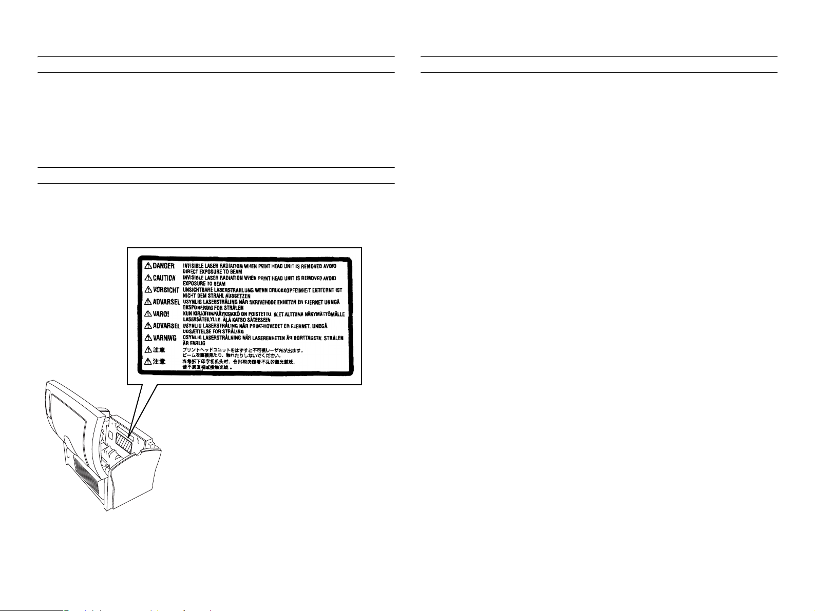
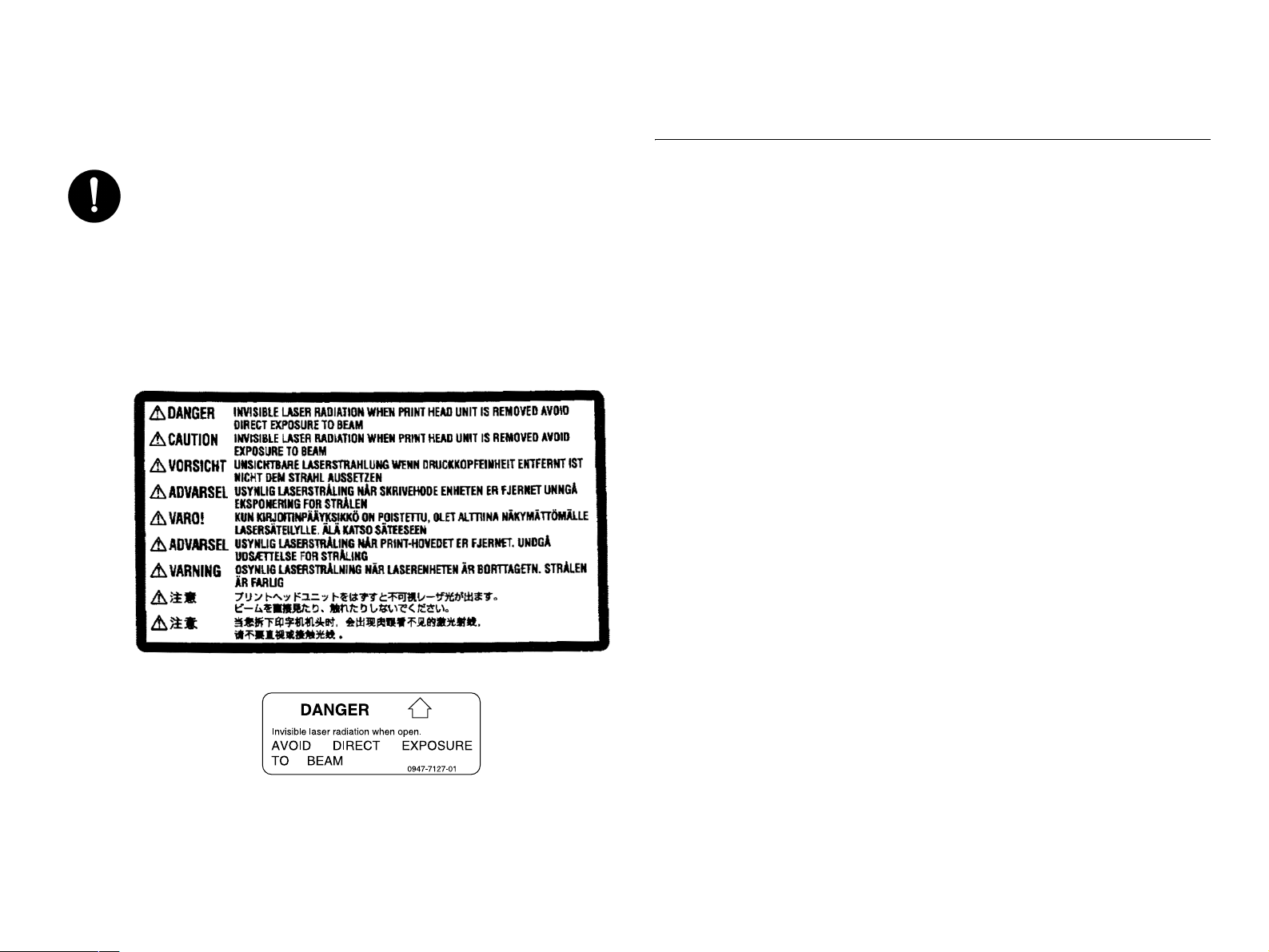
LASER SAFETY LABEL
PRECAUTIONS FOR HANDLING THE LASER EQUIPMENT
A laser safety label is attached to the outside of the machine as shown
below.
LASER CAUTION LABEL
A laser caution label is attached to the inside of the machine as shown
below.
When laser protective goggles are to be used, select ones with a
lens conforming to the above specifications.
When a disassembly job needs to be performed in the laser beam
path, such as when working around the printerhead and PC Drum,
be sure first to turn the printer OFF.
If the job requires that the printer be left ON, take off your watch and
ring and wear laser protective goggles.
A highly reflective tool can be dangerous if it is brought into the laser
beam path. Use utmost care when handling tools on the user's
premises.
CAUTION
Page 17

Revision Status
Revision Date of Issue Description
0 July 2, 2001 Partial release (Chapter 1/ Chapter4) (provisional)
A September 20, 2001 Formal first release
B February 7, 2002 [Revised] The sections listed below are revised.
Chapter 1: Table 1-47. Printer Messages (Only with EPL-5900)
Chapter 3: Table 3-1. Service Call Error (Engine-Related)
Chapter 7: 7.4 Exploded Diagrams
Chapter 7: 7.5 ASP List
Page 18

EPSON EPL-5900/EPL-5900L Revision B
Contents
Chapter 1 Product Description
1.1 Outline ...................................................................................................... 5
1.1.1 Features............................................................................................. 5
1.1.2 “EPL-5900” Differences from EPL-5800 ........................................ 7
1.1.3 “EPL-5900L” Differences from EPL-5800L ................................... 7
1.1.4 “EPL-5900L” Differences from EPL-5900...................................... 7
1.1.5 Restrictions on Use of “EPL-5900L”............................................... 8
1.2 Basic Specifications.................................................................................. 8
1.2.1 Process Specifications ...................................................................... 8
1.2.2 Printer Basic Specifications.............................................................. 8
1.2.3 Various Sensors .............................................................................. 16
1.2.4 Paper Specification......................................................................... 17
1.2.4.1 Paper Type........................................................................................... 17
1.2.4.2 Paper Feedings .................................................................................... 17
1.2.4.3 Printable Area...................................................................................... 17
1.2.5 Reliability, Durability, Serviceability............................................. 18
1.2.6 Operating Conditions (Including Imaging Cartridge) .................... 20
1.2.7 Storage and Transport of the Printer Main Unit and Optional Products
(Consumables Packaged)......................................................................... 21
1.2.8 Electrical Features .......................................................................... 22
1.2.9 Compliance with Standards and Regulations ................................. 22
1.2.10 Consumable Components............................................................. 23
1.2.10.1 Specifications .................................................................................... 23
1.2.10.2 Packing Storage and Transport Environments .................................. 24
1.3.1 Overall Dimensions of EPL-5900 .................................................. 25
1.3.2 Overall Dimensions of EPL-5900L................................................ 26
1.3.3 Names of Parts of EPL-5900.......................................................... 27
1.3.4 Names of Parts of EPL-5900L ....................................................... 29
1.4 Controller Specification.......................................................................... 31
1.4.1 Basic Controller Specifications ...................................................... 31
1.4.2 External I/F Specifications ............................................................. 32
1.4.2.1 Parallel Interface Specifications.......................................................... 33
1.4.2.2 USB Interface...................................................................................... 34
1.4.2.3 Type B Interface (Not Available with EPL-5900L)............................ 34
1.5 Control Panel........................................................................................... 36
1.5.1 External Appearance and Names of Parts....................................... 36
1.5.2 List of Panel Settings (Only with EPL-5900)................................. 38
1.5.2.1 Setting Items (Model-dependent) (Only with EPL-5900)................... 43
1.5.3 Printer Messages (Only with EPL-5900)........................................ 45
1.5.3.1 Status Specifications (Model-dependent)............................................ 47
1.7 System Requirements (Only for EPL-5900L)......................................... 50
1.9 Paper Feed Specifications (Only for EPL-5900L).................................. 52
1.9.1 Paper Size ....................................................................................... 52
1.9.2 Paper Feed Specifications............................................................... 52
1.9.3 Case List ......................................................................................... 53
1.9.4 Special Notes .................................................................................. 53
1.10 Notes on Operation ............................................................................... 54
1.10.1 Powering Off (EPL-5900) ............................................................ 54
1.10.2 Caution About Hot Parts (EPL-5900/EPL-5900L)....................... 54
1.10.3 About the Moist Environment Mode Select Jumper (EPL-5900L) 54
1.11 Engine Environment Setting ................................................................. 55
1.12 Ambient Conditions .............................................................................. 55
1.13 Differences in Specifications between Intended Markets..................... 56
1.13.1 Differences in Specifications ........................................................ 56
1.13.2 Jumper Setting .............................................................................. 57
Chapter 2 Operating Principles
2.1 Overview................................................................................................. 59
2.1.1 EPL-5900 Major Components ........................................................ 59
2.1.2 EPL-5900L Major Components...................................................... 60
1
Page 19

EPSON EPL-5900/EPL-5900L Revision B
2.1.3 Drive System .................................................................................. 61
2.1.4 Names and Functions of Electrical Parts (Printer Body)................ 62
2.1.5 Names and Functions of Electrical Parts (Lower Cassette)
(Not Applicable to EPL-5900L).............................................................. 63
2.1.6 Timing Chart .................................................................................. 64
2.2 Description of Mechanisms .................................................................... 65
2.2.1 Paper Path....................................................................................... 65
2.2.2 Paper Feed Mechanism................................................................... 66
2.2.2.1 Paper Tray ........................................................................................... 66
2.2.2.2 Lower Cassette Unit (Option for EPL-5900) ...................................... 67
2.2.3 Charging Process ............................................................................ 69
2.2.4 Exposure Process............................................................................ 70
2.2.5 Development Process ..................................................................... 71
2.2.6 Transfer Process ............................................................................. 72
2.2.7 Fusing Process ................................................................................ 73
2.2.8 Paper Eject Process......................................................................... 75
2.3 Operating Principles of Electric Circuitry .............................................. 76
2.3.1 Operation Overview of the Main Control Circuit Board................ 76
Chapter 3 Troubleshooting
3.1 Overview................................................................................................. 80
3.1.1 Specified Tools............................................................................... 80
3.1.2 Procedure for Troubleshooting....................................................... 80
3.1.3 Printer Messages (EPL-5900)......................................................... 80
3.1.3.1 Service Call Error................................................................................ 80
3.1.4 Printer Messages (EPL-5900L) ...................................................... 84
3.1.4.1 Printer Status. ...................................................................................... 84
3.1.4.2 Engine Error ........................................................................................ 84
3.1.5 Paper Jam Detection ....................................................................... 85
3.1.5.1 Overview ............................................................................................. 85
3.1.5.2 Paper Jam Conditions .......................................................................... 85
3.1.5.3 Resetting the Paper Jam ...................................................................... 85
3.1.6 Detection of Abnormal Operations ................................................ 86
3.2 Troubleshooting for Paper Jam............................................................... 87
3.2.1 Paper Jam when the Power is ON .................................................. 87
3.2.2 Paper Jam in Paper Feed to Paper Transport.................................. 87
3.2.3 Paper Jam in Paper Transport to Paper Eject.................................. 88
3.3 Troubleshooting for Abnormal Operations............................................. 89
3.3.1 Abnormal Laser .............................................................................. 89
3.3.2 Abnormal Polygon Motor............................................................... 89
3.3.3 Abnormal Main Motor.................................................................... 89
3.3.4 Abnormal Fusing ............................................................................ 89
3.3.5 Power Cannot be Turned ON.......................................................... 90
3.4 Troubleshooting for Print Quality Problems........................................... 91
3.4.1 All White......................................................................................... 91
3.4.2 All Black ......................................................................................... 91
3.4.3 White Out........................................................................................ 92
3.4.4 Back of Paper Gets Dirty ................................................................ 92
3.4.5 Low Image Density......................................................................... 92
3.4.6 Foggy Background.......................................................................... 92
3.4.7 White Line / Black Line.................................................................. 93
3.4.8 Offset Image ................................................................................... 93
Chapter 4 Disassembly and Assembly
4.1 Overview................................................................................................. 95
4.1.1 Precautions...................................................................................... 95
4.1.2 Tools ............................................................................................... 97
4.1.3 Screws............................................................................................. 97
4.2 Main Unit Disassembly........................................................................... 98
4.2.1 Preparation before Disassembling .................................................. 99
4.2.2 Imaging Cartridge and Drum Cartridge Removal .......................... 99
4.3 Disassembly and Reassembly of the Printer Body ............................... 100
4.3.1 Transfer Roller Removal .............................................................. 100
4.3.2 Paper Separator Unit Removal ..................................................... 101
4.3.3 Right Cover Removal ................................................................... 101
4.3.4 Control Panel Removal................................................................. 102
4.3.5 Main Board Assy Removal........................................................... 103
4.3.6 Interface Board (C409I/F) Removal............................................. 104
4.3.7 Left Cover Removal...................................................................... 105
4.3.8 Front Cover Removal.................................................................... 105
4.3.9 Paper Feed Roller Removal .......................................................... 106
2
Page 20

EPSON EPL-5900/EPL-5900L Revision B
4.3.10 Printing Head Unit Removal ...................................................... 106
4.3.11 Paper Empty Sensor (PE1) Removal.......................................... 107
4.3.12 Top Cover and Rear Cover Removal ......................................... 107
4.3.13 Fuser Unit Removal.................................................................... 108
4.3.14 Fuser Unit Disassembly.............................................................. 109
4.3.15 Power Supply Unit and High Voltage Board Removal.............. 113
4.3.16 Main Motor Assy (M1) Removal ............................................... 115
4.4 500-sheet Lower Cassette Unit (Optional) ........................................... 117
4.4.1 Second Paper Feed Roller Removal ............................................. 117
4.4.2 Second Paper Feed Unit Removal................................................ 118
4.4.3 Relay Board (PWB-A) Removal .................................................. 119
4.4.4 Cassette Type Detect Switch (SW21) Removal........................... 119
4.4.5 Second Paper Feed Solenoid (SL21) Removal ............................ 120
Chapter 5 Adjustment
5.1 Overview............................................................................................... 122
5.2 USB ID Input........................................................................................ 123
5.2.1 Installation Procedure for Program .............................................. 123
5.2.2 Procedure for Program Operation ................................................ 123
5.2.3 USB ID Confirmation................................................................... 125
7.1.1.5 HV1 (High Voltage Unit) Board....................................................... 131
7.2 Circuit Board Component Layout......................................................... 132
7.3 Circuit Diagrams ................................................................................... 137
7.4 Exploded Diagrams............................................................................... 145
7.5 ASP List ................................................................................................ 158
Chapter 6 Maintenance
6.1 Overview............................................................................................... 127
6.1.1 Cleaning........................................................................................ 127
6.1.2 Maintenance ................................................................................. 127
Chapter 7 Appendix
7.1 Connectors ............................................................................................ 129
7.1.1 Circuit Boards............................................................................... 129
7.1.1.1 Connectors on Main Board Assy (EPL-5900) .................................. 129
7.1.1.2 Connectors on Main Board Assy (EPL-5900L)................................ 130
7.1.1.3 Interface Board (C409I/F)................................................................. 131
7.1.1.4 PU1 (Power Supply Unit) Board....................................................... 131
3
Page 21

PRODUCT DESCRIPTION
CHAPTER
1
Page 22

EPSON EPL-5900/EPL-5900L Revision B
1.1 Outline
EPSON EPL-5900 and EPL-5900L are non-impact page printer with semi-conductor
laser and electrophotographic technology.
1.1.1 Features
ENGINE FEATURES
New compact and lightweight, A4 support engine
Resolution/ printing speed: See table below.
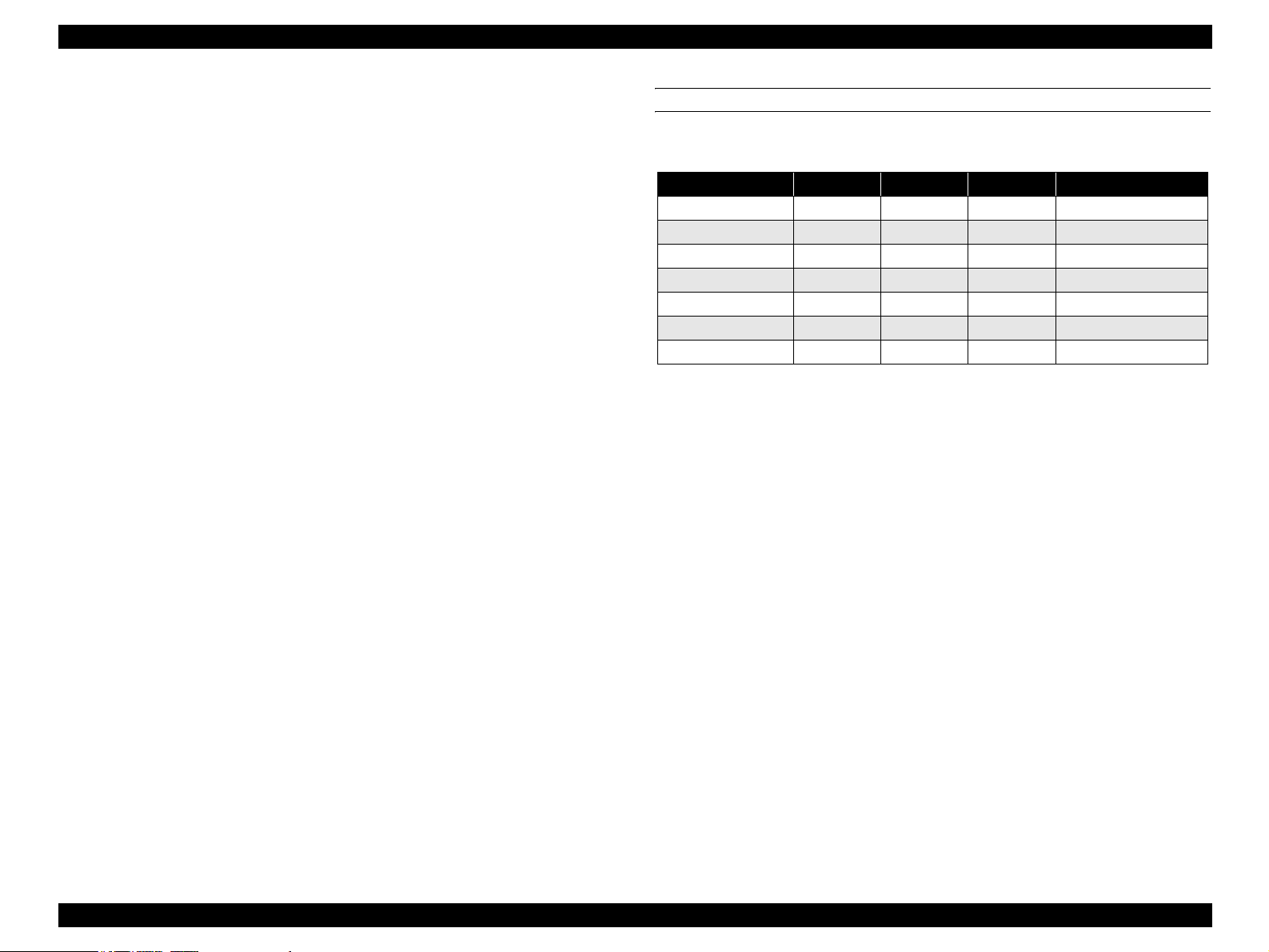
Table 1-1. Resolution and Printing Speed
Model Resolution Printing Speed
EPL-5900
EPL-5900L 600 dpi 12 ppm
Note: The engine itself supports True 1200 dpi, but 1200 dpi is not
supported with EPL-5900L.
With EPL-5900, the standard paper supply consists of the cassette-like universal
paper tray (250 sheets) and manual feed tray (one sheet).
EPL-5900L is equipped with a 150-sheet paper feed tray.
EPL-5900 supports an optional 500-sheet lower cassette (A4).
Toner life: 3,000 pages with the pre-installed Imaging Cartridge and 6,000 sheets
with a replaced Imaging Cartridge.
Neither the pre-installed Imaging Cartridge nor replaced Imaging Cartridge is
interchangeable with that for EPL-5800 or EPL-5800L series.
300 dpi / 600 dpi 12 ppm
1200 dpi 6 ppm
CONTROLLER FEATURES
<EPL-5900>
High-speed controller, employing new CPU
CPU = TMPR4955AF / Clock = 200 MHz
8 MB fitted as standard RAM and Expandable up to 136 MB Max.
PCL6 emulation installed
Two standard interfaces
IEEE1284 parallel interface
USB interface
Equipped with one Type B interface slot (Level 3 supported)
Real 1200dpi supported (Only in ESC/Page, PCL6, PostScript 3. Up to 600 dpi
supported in other modes)
Note: 1200dpi printing needs much memory then the possibility of running
short of memory is high with standard memory.
Recommendation: Extension of 16MB or more.
EnhancedMicroGray installed (available only in 600dpi and 300dpi.
Automatically switched Off when 1200dpi is selected.)
RITech installed (available only in 600dpi and 300dpi. Automatically switched
Off when 1200dpi is selected.)
New control panel design with 3 switches and 6 LEDs
The Photoconductor Unit is common to EPL-5900 Series and EPL-5800 Series.
The face down tray attachment is available as an option.
Note: This attachment is not a general option. It is supplied on user request
or tender request. The capacity depends on user environment. This
attachment is not described in manuals or catalogs.
Product Description Outline 5
Page 23
EPSON EPL-5900/EPL-5900L Revision B
<EPL-5900L>
Host based controller
CPU Toshiba TMP95C001 24MHz
RAM Standard 2MB
Expandable up to a maximum of 13 MB (EDO RAM SIMM,
access speed 60 ns).
Two standard interfaces
IEEE1284 parallel interface (ECP supported)
USB interface (UBS Revision 1.1, USB ID supported)
RITech, EnhancedMicroGray functions installed
Data Compression Technologies
By sending compressed data from the host computer, almost all data can be
printed only with the standard memory.
High speed processing is realized by use of the expansion circuit hardware.
Expansion of RAM will enhance the following functions and speed up printing.
EnhancedMicroGray printing
Increasing the size of the receiving buffer
High-speed printing
SOFTWARE FEATURE (ONLY WITH EPL-5900)
The following modes and resolution are supported.
Table 1-2. Supported Modes
Mode 1200dpi 600dpi 300dpi Note
ESC/Page {{{
PCLXL { { {
PCL5e x {{
ESC/P2 x { {
FX x {{
1239X x { {
PostScript {{{Optional (New)
NLSP is included in the main unit font ROM
Compatible with USB Revision 1.1
Job cancellation by panel switch
Product Description Outline 6
Page 24

EPSON EPL-5900/EPL-5900L Revision B
1.1.2 “EPL-5900” Differences from EPL-5800
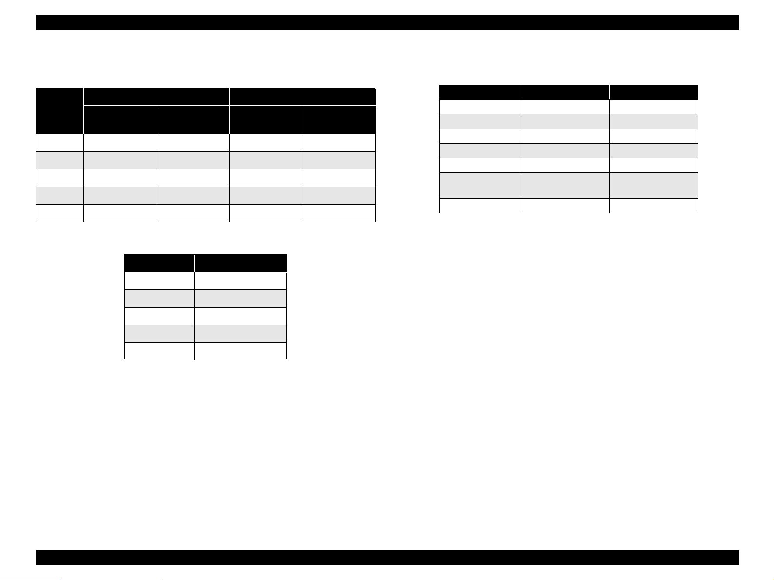
Table 1-3. EPL-5900 Differences from EPL-5800
Item EPL-5900 EPL-5800 Note
Engine speed 12 ppm 10 ppm
CPU performance TMPR4955AF-200MHz R4310-133MHz
RAM capacity
(Standard / Maximum)
Paper size at shipment A4 only A4/Letter
Control Panel 3 switches, 6 LEDs 4 switches, 6 LEDs
LED Status New specifications
Status Sheet New format
Photoconductor Unit
life indicator
Consumables
information
Selectype
Preprinted: LC Type/
MP Type
Parallel Menu Bi-D
default value
Standby time 15 minutes 5 minutes
Optional Letter cassette
unit
8MB / 136MB 16MB / 256 MB
Included Not included
Indicated Not indicated
Deleted Available
ECP Nibble
None Available
1.1.4 “EPL-5900L” Differences from EPL-5900
Compatible with Windows (Windows 95/98/2000, NT 4.0) and Macintosh (Mac
OS 8.1 or later) OS only.
Not compatible with the other operating systems, such as DOS, Unix or Linux.
As for Macintosh, EPL-5900L is compatible with only those models which
support the standard USB port.
Even in Windows environments, EPL-5900L is not compatible with any machine
with a connection port other than the standard USB port.
EPL-5900L is not equipped with fonts and emulations.
No emulations are offered as options.
In image printing, output results may differ, since the ROP and filling methods as
well as the half-tone screen, etc. differ.
1200 dpi resolution is not supported.
Only EDO RAM SIMM (with an access speed of 60 ns or less) is supported for
expansion RAM.
Not compatible with direct connection to a network.
Can be used as a Shared Printer in both Windows environments and Macintosh
environments.
The standard paper feeder is a folding tray type.
No optional lower cassette is available.
No switches on the control panel
1.1.3 “EPL-5900L” Differences from EPL-5800L
The standard paper feeder is a folding tray type.
Printing speed 12 ppm (EPL-5800L: 10 ppm)
“Toner Out” setting added (already employed with EPL-1220)
“Invalid Size” error added (already employed with EPL-1220)
The Check Paper Size error and Check Multi Copy P-Size error are not
implemented.
Product Description Outline 7
Page 25

EPSON EPL-5900/EPL-5900L Revision B
1.1.5 Restrictions on Use of “EPL-5900L”
The Status Sheet can not be printed out with the printer unit in the stand alone
state.
If the printer is connected to the parallel interface through a printer switching
device, LAN-Parallel switching device, USB-Parallel switching device or any
other like device, printing performance is not guaranteed.
⇒ Direct connection to the host's printer port via an ECP compatible cable is
premised.
For USB connection, use of a switching device is not covered by the warranty.
With a host computer that does not permit ECP connection, printing with the
standard memory may be impossible in some cases.
The maximum RAM size is 13 MB (even when 16/32 MB RAM SIMM is
installed).
EPL-5900L can not be used in a system incorporating a terminal server or any
other device which does not support bidirectional communication.
1.2 Basic Specifications
1.2.1 Process Specifications
Printer Type
Semi-conductor laser beam scan and dry one-component electromagnetic toner
electrophotography
Light Source
Semi-conductor laser
Photoconductor Unit
OPC (organic photoconductor) drum
Charging
Rotary-brush charging method
Development
Exposed area development
Toner
One-component magnetic toner
Transfer
Roller transfer method
Fixing
Heated roller method
Density Adjustment
Variable development bias method (adjustable by user)
1.2.2 Printer Basic Specifications
Resolution:
<EPL-5900> 600dpi / 1200dpi
(1200dpi is half speed control)
<EPL-5900L> 600 dpi
Warming Up Time:
21 or less seconds ....... Time from power-on to “Ready” display
11 or less seconds ........Warm-up time from sleep mode
(23°C environment, at rated voltage)
Product Description Basic Specifications 8
Page 26
EPSON EPL-5900/EPL-5900L Revision B
First Printing Time: Continuous Printing Speed:
Table 1-4. First Printing Time with “EPL-5900”
600dpi 1200dpi
Paper Size
Main Unit
A4 15 sec. maximum 16 sec. maximum 24 sec. maximum 26 sec. maximum
LGL 16 sec. maximum -- 25 sec. maximum --
LT 15 sec. maximum 16 sec. maximum 24 sec. maximum 26 sec. maximum
B5 15 sec. maximum -- 23 sec. maximum --
A5 14 sec. maximum -- 22 sec. maximum --
Lower Cassette
Unit
Main Unit
Lower Cassette
Unit
Table 1-5. First Printing Time with “EPL-5900L”
Paper Size 600dpi
A4 15 sec. maximum
LGL 16 sec. maximum
LT 15 sec. maximum
B5 15 sec. maximum
A5 14 sec. maximum
Table 1-6. Continuous Printing Speed
Paper Size 600dpi 1200dpi
A4 12.0 ppm minimum 6.0 ppm minimum
LGL 10.3 ppm minimum 5.1 ppm minimum
LT 12.5 ppm minimum 6.2 ppm minimum
B5 12.5 ppm minimum 6.2 ppm minimum
A5 12.5 ppm minimum 6.2 ppm minimum
Japanese official
postcard
Kakugata #3
*1: 1200 dpi is not available with EPL-5900L.
*2: JIS envelope
NOTE 1:
The continuous printing speeds indicated above are common to all the paper
*2
12.5 ppm minimum 6.2 ppm minimum
11.0 ppm minimum 5.5 ppm minimum
feeders.
2:
For printing of custom size paper, printing speed will be lower because
automatic cleaning is carried out. In addition, paper sheets of custom size
will be printed at the same speed irrespective of the paper size.
Paper Feed Reference
Centerline reference for each paper size and each paper feeder.
*1
Product Description Basic Specifications 9
Page 27
EPSON EPL-5900/EPL-5900L Revision B
Paper Feed:
Table 1-7. Paper Feed with “EPL-5900”
Paper Source Capacity Paper Type *1 and Paper Size
Paper Tray
Standard
Manual
feed slot
500-sheet
lower
cassette
(paper size
Optional
fixed)
300 sheets
(TBD)
250 sheets
5 sheets
10 sheets
10 sheets
50 sheets
1 sheet
TBD sheets
500 sheets
Standard paper: FX P Paper: A4
Standard paper: XEROX 4024DP 20lb: Letter
Plain paper or regenerated paper:
A4, B5, A5, Letter, GLT, Executive, LGL
GLG, F4, Half Letter, Custom size paper
Transparencies:
A4, B5, A5, Letter, GLT, Executive, LGL,
GLG, F4, Half Letter, Custom size paper
Labels:
A4, B5, A5, Letter, GLT, Executive, LGL,
GLG, F4, Half Letter, Custom size paper
Thick paper:
A4, B5, A5, Letter, GLT, Executive, LGL,
GLG, F4, Half Letter, Custom size paper
Envelope:
Monarch, Com-10
ISO-B5, Yokei #0
*4
, Chokei #3 *4, Chokei #4 *4, Kakugata #3
Japanese official postcard *2,
*3
Japanese official prepaid postcard
, DL, C5, C6
*4
, Yokei #4 *4, Yokei #6
*2
Standard paper, plain paper, special
applications:
A4, A5, Letter, GLT, Executive, LGL, GLG
F4, Half Letter, B5, Monarch, Com-10 DL,
*4
C5, C6, ISO-B5, Yokei #0
*4
Yokei #6
, Chokei #3 *4, Chokei #4 *4,
, Yokei #4 *4,
Kakugata #3 *4, Custom size paper
*
Standard paper: FX P Paper: A4
Standard paper: XEROX 4024DP 20lb: Letter
Plain paper or regenerated paper: A4 or Letter
Thickness
60 ~ 90 g/m
90 ~ 163 g/m
70 ~ 105 g/m
*4
60 ~ 163 g/m
60 ~ 90 g/m
Feedable
Paper
2
64 g/m
2
75 g/m
---
---
190 g/m
2
64 g/m
2
75 g/m
*1
2
Paper Source Capacity Paper Type *1 and Paper Size
Paper Tray
Standard
2
2
2
*1: Refer to 1.2.4 "Paper Specification".
2
*2: Curl must be straightened, especially before feeding a postcard for printing of its back
side in consideration of manual duplex printing. (Set the postcard so that its side to be
printed faces up and its curl is directed upward.)
*3: For the second side printing, set not more than 20 sheets.
*4: JIS envelope
NOTE: For custom size paper, refer to Paper Feed Sizes and Paper Thickness
2
(p13).
Table 1-8. Paper Feed with “EPL-5900L”
300 sheets
(TBD)
150 sheets
5 sheets
10 sheets
10 sheets
50 sheets
Standard paper: FX P Paper: A4
Standard paper: XEROX 4024DP 20lb: Letter
Plain paper or regenerated paper:
A4, B5, A5, Letter, GLT, Executive, LGL
GLG, F4, Half Letter, Custom size paper
Transparencies:
A4, B5, A5, Letter, GLT, Executive, LGL,
GLG, F4, Half Letter, Custom size paper
Labels:
A4, B5, A5, Letter, GLT, Executive, LGL,
GLG, F4, Half Letter, Custom size paper
Thick paper:
A4, B5, A5, Letter, GLT, Executive, LGL,
GLG, F4, Half Letter, Custom size paper
Envelope:
Monarch, Com-10
ISO-B5, Yokei #0
*4
, Chokei #3 *4, Chokei #4 *4, Kakugata #3
Japanese official postcard *2,
*3
, DL, C5, C6
*4
, Yokei #4 *4, Yokei #6
Japanese official prepaid postcard
Feedable
Paper
Thickness
64 g/m
75 g/m
60 ~ 90 g/m
---
---
90 ~ 163 g/m
70 ~ 105 g/m
*4
*2
190 g/m
*1
2
2
2
2
2
2
Product Description Basic Specifications 10
Page 28
EPSON EPL-5900/EPL-5900L Revision B
Applicable Paper Sizes, Paper Types, and Paper Orientation
Table 1-9. Applicable Paper Sizes, Paper Types, and Paper Orientation
with “EPL-5900”
Paper Size
A4 210.00
A5 148.00× 210.00
B5 182.00 × 257.00
LT
HLT
LGL)
Plain Paper
EXE
GLG
GLT
F4 210.00
Japanese official
postcard
Japanese official
prepaid postcard
Transparencies
Special Applications
Labels
*4
*4
Dimensions
in mm (inches)
215.90
(8.50× 11.00")
139.70× 215.90
(5.50× 8.50")
215.90
×14.00")
(8.50
184.15× 266.70
(7.25× 10.50")
215.90× 330.20
×13.00")
(8.50
203.20× 266.70
(8.00× 10.50")
100.00× 148.00
200.00× 148.00
A4: 210.00×297.00
LT: 215.90×279.40
A4: 210.00×297.00
LT: 215.90×279.40
×297.00
×279.40
×355.60
×330.00
Paper
Tray
Manual
Feed
Slot
{{{
{ {
{ {
{{{
{ {
{{
{ {
{{
{ {
{{
{ {
{{
{ {
{{
Lower
Cassette
*4
*3
- SEF
- SEF
*3
-SEF
- SEF
-SEF
- SEF
-SEF
- SEF
-SEF
- SEF
-SEF
Paper
Orientation
SEF
SEF
SEF
Table 1-9. Applicable Paper Sizes, Paper Types, and Paper Orientation
with “EPL-5900” (continued)
Paper Size
Monarch
Com-10
DL 110.00×220.00
C5 162.00 × 229.00
C6 114.00 × 162.00
*3, *4
ISO-B5 176.00×250.00
Yokei #0
Envelope
Yokei #4
Special Applications
Yokei #6
Chokei #3 *5120.00×235.00
Chokei #4 *590.00×205.00
Kakugata #3 *5216.00×277.00
*1: Curls must be straightened.
*2: Refer to Envelope Orientation (p.13) for details on feeding direction of envelopes.
*3: The lower cassette is available with a fixed paper size.
*4: Option
*5: JIS envelope
*5
*5
*5
Dimensions
in mm (inches)
98.43×190.50
(3 7/8”×7 1/2”)
×241.30
104.78
×9 1/2”)
(4 1/8”
120.00×235.00
105.00×235.00
98.00×190.00
Paper
Tray
Manual
Feed
Slot
{ {
{{
{ {
{{
{ {
{{
{ {
{{
{ {
{{
{ {
{{
Lower
Cassette
*4
- SEF
-SEF
- SEF
-SEF
- SEF
-SEF
-SEF
-SEF
Paper
Orientation
SEF
SEF
SEF
SEF
NOTE: LEF (Long Edge Feed): the long edge of the paper is fed to the printer.
SEF (Short Edge Feed): the short edge of the paper is fed to the printer.
*2
*2
*2
*2
*2
*2
*2
*2
*2
*2
*2
*2
Product Description Basic Specifications 11
Page 29
EPSON EPL-5900/EPL-5900L Revision B
Table 1-10. Applicable Paper Sizes, Paper Types, and Paper Orientation
Table 1-10. Applicable Paper Sizes, Paper Types, and Paper Orientation
with “EPL-5900L”
Paper Size
A4 210.00
A5 148.00 ×210.00
B5 182.00× 257.00
LT
HLT
LGL)
Plain Paper
EXE
GLG
GLT
F4 210.00
Japanese official
postcard
Japanese official prepaid
postcard
Transparencies
Special Applications
Labels
*4
*4
in mm (inches)
215.90
×11.00")
(8.50
139.70×215.90
(5.50×8.50")
215.90×355.60
(8.50×14.00")
184.15×266.70
×10.50")
(7.25
215.90×330.20
(8.50×13.00")
203.20×266.70
×10.50")
(8.00
100.00×148.00
200.00×148.00
A4: 210.00×297.00
LT: 215.90
A4: 210.00×297.00
LT: 215.90×279.40
Dimensions
×297.00
×279.40
×330.00
×279.40
Paper Tray
{
{
{
{
{
{
{
{
{
{
{
{
{
{
Paper
Orientation
SEF
SEF
SEF
SEF
SEF
SEF
SEF
SEF
SEF
SEF
SEF
SEF
SEF
SEF
Paper Size
Monarch
Com-10
DL 110.00×220.00
C5 162.00×229.00
C6 114.00×162.00
*3, *4
ISO-B5 176.00×250.00
Yokei #0
Envelope
Special Applications
*1: Curls must be straightened.
*2: Refer to Envelope Orientation (p.13) for details on feeding direction of envelopes.
*3: JIS envelope
Yokei #4
Yokei #6
Chokei #3
Chokei #4
Kakugata #3
NOTE: LEF (Long Edge Feed): the long edge of the paper is fed to the printer.
SEF (Short Edge Feed): the short edge of the paper is fed to the printer.
with “EPL-5900L” (continued)
Dimensions
in mm (inches)
98.43×190.50
(3 7/8”×7 1/2”)
×241.30
104.78
(4 1/8”×9 1/2”)
*3
*3
*3
*3
*3
120.00×235.00
105.00×235.00
98.00×190.00
120.00×235.00
90.00×205.00
*3
216.00×277.00
Paper Tray
{
{
{
{
{
{
{
{
{
{
{
{
Paper
Orientation
*2
SEF
*2
SEF
*2
SEF
*2
SEF
*2
SEF
*2
SEF
*2
SEF
*2
SEF
*2
SEF
*2
SEF
*2
SEF
*2
SEF
Product Description Basic Specifications 12
Page 30
EPSON EPL-5900/EPL-5900L Revision B
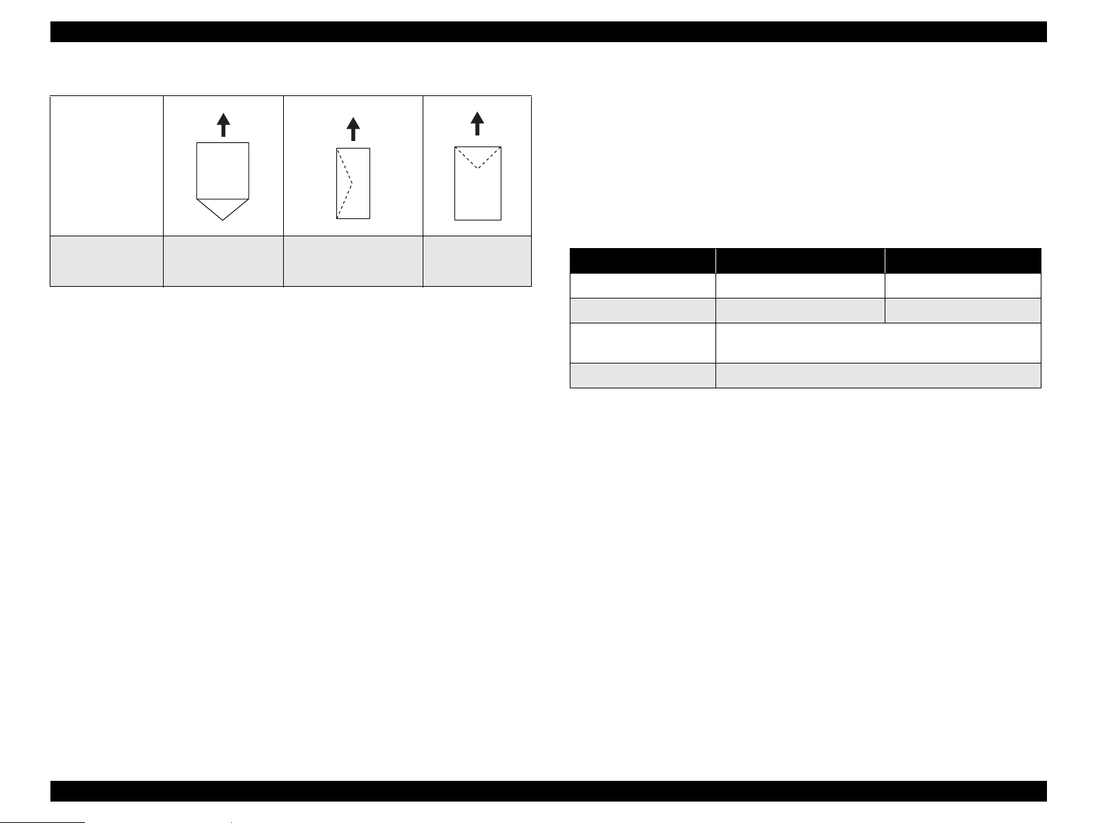
Envelope Orientation
<EPL-5900L>
Paper tray:
Regular types of paper or custom size paper within the following feedable
paper size range
Feeding Direction
Paper width 76.00 to 216.00 mm
Paper length 127.00 to 356.00 mm
Paper thickness 60 to 163 g/m
2
Output Paper Capacity:
Table 1-11. Output Paper Capacity
Standard Optional
*1
100 sheets 20 sheets
All sizes which can be fed through the printer body
(Regular or custom sizes)
Standard paper, plain paper, special applications
Envelope Types
*1: JIS envelope
Chokei #3 *1,
Chokei #4 *1,
Kakugata #3
Yokei #0 *1, Yokei #4 *1,
*1
Yokei #6 *1, Monarch,
Com-10, DL, C6
C5, ISO-B5
NOTES:1. Only envelopes without adhesive or adhesive tapes can be used.
2. Set the envelope with its side to be printed facing up.
Paper Feed Sizes and Paper Thickness
Paper exit bin Face-down Face-up
Output paper capacity
Paper sizes
Paper types
*2
<EPL-5900>
Printer body and Paper tray:
Regular types of paper or custom size paper within the following feedable
*1: In Environment A (see p.55). With standard paper immediately after unpacked
*2: Refer to 1.2.4 "Paper Specification".
paper size range
Paper width 76.00 to 216.00 mm
Paper length 127.00 to 356.00 mm
Paper thickness 60 to 163 g/m
2
Manual feed slot:
Regular types of paper or custom size paper within the following feedable
paper size range
Paper width 76.00 to 216.00 mm
Paper length 148.00 mm to 356.00 mm
Paper thickness 60 to 163 g/m
2
Lower cassette unit (option):
Supported paper size = Either A4 or Letter (fixed to only one size)
Paper thickness 60 to 90 g/m
2
Product Description Basic Specifications 13
Page 31

EPSON EPL-5900/EPL-5900L Revision B
Dimensions
Stand Alone Outline Dimensions and Weights
Table 1-12. Stand Alone Outline Dimensions and Weights of
“EPL-5900”
Standard
Optional
Standard
Optional
NOTE 1:
Face-down tray in storage position
Face-down tray in use position
Face-up tray
Lower cassette unit
Table 1-13. Stand Alone Outline Dimensions and Weights of
“EPL-5900L”
Face-down tray in storage position
Face-down tray and Paper tray in
use position
Face-up tray
Unpacked dimensions are stated.
2:
Dimensions have a tolerance of ±5mm and weights have a tolerance of
±
0.5kg.
3:
The dimensions of the Main Unit does not include those of the controller and
consumables.
Width
(mm)
399 435 265 7.5
399 435 378 7.5
248 32 248 0.2
382 444 137 4
Width
(mm)
399 263 256 7
399 406 368 7
248 32 248 0.2
Depth
(mm)
Depth
(mm)
Height
(mm)
Height
(mm)
Weight
Weight
(kg)
(kg)
Outline Dimensions and Weights with Options Installed
Table 1-14. Outline Dimensions and Weights with Options Installed of
“EPL-5900”
Main Unit +
Face-up tray
Main Unit +
Lower cassette unit
Main Unit +
Lower cassette unit +
Face-up tray
Main Unit +
Paper eject tray
attachment
NOTE 1:
Dimensions have a tolerance of ±5mm and weights have a tolerance of
±
0.5kg.
2:
The dimensions of the Main Unit does not include those of the controller and
consumables.
Face-down and
Face-up trays in
storage position
Face-up tray in use
position
Face-down tray in
storage position
Face-down tray in
use position
Face-down tray in
use position
Face-down tray in
storage position
Face-down tray in
use position
Width
(mm)
399 435 269 7.7
399 569 428 7.7
399 444 377 11
399 444 491 11
399 578 541 11.2
399 435 276 7.1
399 435 287 7.1
Depth
(mm)
Height
(mm)
Weight
(kg)
Product Description Basic Specifications 14
Page 32

EPSON EPL-5900/EPL-5900L Revision B
Consumables:
Table 1-15. Outline Dimensions and Weights with Options Installed of
“EPL-5900L”
Main Unit +
Face-up tray
Main Unit +
Paper eject tray
attachment
NOTE 1:
2:
Width
(mm)
Face-down and
Face-up trays and
Paper tray in storage
position
Face-up tray and
Paper tray in use
position
Face-down tray and
Paper tray in storage
position
Face-down tray and
Paper tray in use
position
399 397 280 7.2
399 540 418 7
399 263 267 7.1
399 406 278 7.1
Dimensions have a tolerance of ±5mm and weights have a tolerance of
±
0.5kg.
The dimensions of the Main Unit does not include those of the controller and
Depth
(mm)
consumables.
Height
(mm)
Weight
(kg)
Imaging Cartridge (black toner)
Drum Cartridge (Photoconductor Unit)
Note: Refer to 1.2.10 "Consumable Components".
Regular Replacement Parts
Without taking into account replacement by the user, the lives of regular
replacement parts are as follows:
Fuser Unit..........................50,000 pages (5% pattern continuous printing)
Transfer Roller ..................50,000 pages (5% pattern continuous printing)
Power Supply:
100V ±10% 50 ∼ 60Hz ±3Hz
110V
−
10% 50 ∼ 60Hz ±3Hz
127V
+6
% 50 ∼ 60Hz ±3Hz
220
∼
240V ±10%50 ∼ 60Hz ±3Hz
Applicable low-voltage power supplies are 100~120 V and 220~240 V only.
Power Consumption
Table 1-16. Power Consumption
100V 120V 200V System
Maximum current rated
Maximum
Average at continuous
Power
Consumption
printing
Average during standby
with heating on
Average during power save
mode with heating off
8.6A 7.2A 3.8A
810W 840W 850W
330Wh 330Wh 330Wh
75Wh 75Wh 75Wh
15Wh 15Wh 15Wh
Product Lifetime
Main Unit
180,000 printed pages or 5 years, whichever comes first. (with periodic part
replacement) → See Table 6-2 Regular Replacement Parts and Consumables
Product Description Basic Specifications 15
Page 33

EPSON EPL-5900/EPL-5900L Revision B
Noise
Table 1-17. Noise
During standby During printing
Main Unit only 30.0dB (A) 49.0dB (A)
Exhaust Gas
Ozone Concentration: 0.02 mg/m
(by blue angel mark measurement method)
Styrene Concentration: 0.07 mg/m
(by blue angel mark measurement method)
Dust Concentration: 0.15 mg/m
(by blue angel mark measurement method)
3
max.
3
max.
3
max.
1.2.3 Various Sensors
Table 1-18. Various Sensors of “EPL-5900”
Unit Detectable Matter Sensors Remarks
Standard Paper Tray
Lower
Cassette
Unit
Out of paper
Out of paper
Paper size
Cassette mounted/
unmounted
Automatic detection
by sensor
Automatic detection
by sensor
Automatic setting
with projection on
cassette
Combination of both
detections for “out of
paper” and “paper
size”
Cassette dedicated to A4
or LT
Hazardous Materials
None of the OPC, toner and plastics contains hazardous materials.
Note: For safety standards, refer to 1.2.9 "Compliance with Standards and
Regulations".
Unit Detectable Matter Sensors Remarks
Standard Paper Tray
Table 1-19. Various Sensors of “EPL-5900L”
Out of paper
Automatic detection
by sensor
Product Description Basic Specifications 16
Page 34

EPSON EPL-5900/EPL-5900L Revision B
•
1.2.4 Paper Specification
Four-leaf printed postcard, postcards made for inkjet printing, or presssealed postcards
•
1.2.4.1 Paper Type
Standard Paper
XEROX 4024 DP 20 lb: Letter paper
Plain Paper
2
60 g/m
∼ 90 g/m2 (16 lb ∼ 24 lb)
generally applied copy paper, recycled paper
Iron print coated paper (for inkjet or laser printing)
•
Sheets deteriorate or discolor by heat of the Fuser Unit of approximately 200
°
C
3:
When the Japanese “Kamo mail” post card or official / non-official
postcards with illustrations are used, paper feed roller may be soiled with
paper dust, and these postcards are not fed properly. In this case, cleaning is
required following Table 6-1 Cleaning Items.
Special Applications
Labels
Transparencies
Thick paper (90 ∼ 163 g/m
Envelopes
NOTE 1:
lb: Ream weight = lb / 500 sheets/ 17” ×22” (431.8X558.8mm)
2
g/m
: 1 g/m2 = 0.2659763 lb
2:
The following types of paper should not be used with this printer.
They could cause printing defects, paper jams or printer malfunctions.
•
Carbon paper, non-carbon paper, thermal paper, impact paper, acid-based
paper
•
Paper that is too thin or too thick
•
Paper that is wet or damp
•
Paper with special coatings or colored paper with processed surfaces
•
Glossy (too slick on its surface) paper, or paper with too smooth/rough
surfaces
•
Paper with significantly different roughness on each surface
•
Paper with punch holes or perforations
•
Creased, curled or torn paper
•
Irregularly shaped paper or paper with non-perpendicular corners
•
Labels that peel off easily
•
Paper with glue, staples or paper clips attached to it
•
Ink jet paper for special applications (super-fine, glossy, glossy film, etc.)
•
Paper that was previously used in a thermal or ink jet printer
•
Transparencies for color photocopiers or color laser printers
•
Sheets already printed on other color / monochrome laser printers or
photocopiers
•
Sheets of paper stuck together
2
)
1.2.4.2 Paper Feedings
Table 1-20. Paper Feedings
Standard
Paper
Standard Paper Tray {
Optional
*1: Use of Lower Cassette is not supported with EPL-5900L.
{ : Paper feed reliability and image quality assured.
: Paper feed reliability and image quality assured, but only for the use of generally applied
∆
Lower
Cassette
types of paper.
: Paper feed and printing are possible for only generally applied types of paper.
*1
{ × × × ×
Plain
Paper
Transparencies Labels
Special Applications
Thick
paper
∆∆∆∆
Envelope
× : Sheets cannot be fed.
1.2.4.3 Printable Area
Available Printing Area
208.0 mm × 348.0 mm
Product Description Basic Specifications 17
Page 35

EPSON EPL-5900/EPL-5900L Revision B
Guaranteed Printing Area
All area of the sheet except vertical and horizontal margins of 4 mm (See
illustration below)
4 m m 4 m m
1.2.5 Reliability, Durability, Serviceability
MPBF
25,000 pages
NOTE:
MPBF means an average number of pages printed until the
occurrence of a malfunction which either requires the replacement
of a part or cannot be solved by the user.
Paper Feed Reliability
4 m m
Table 1-21. Paper Feed Reliability
Environment
Error type A B C
G u a r a n t e e d
p r i n t a r e a
Paper-jam rate
Paper misfeed 1/2000 max. 2/2000 max. 3/2000 max.
Multiple-sheet feed rate
Paper creasing 1/1000 max. 2/1000 max. 3/1000 max.
Leading edge folded
*1: Includes miss feeds, multiple-sheet feed, and other kinds of jam. Does not include
multiple-sheet feed at the boundary.
*2: Does not include multiple-sheet feed at the boundary.
•
*3: Includes 1 mm or more corner fold, but does not include less than 1 mm corner fold.
*1
*2
*3
Boundary means sheets boundary between original paper and replenished paper,
occurring after paper is replenished.
1/2000 max. 2/2000 max. 3/2000 max.
1/500 max. 2/500 max. 3/500 max.
1/1000 max. 2/1000 max. 3/1000 max.
4 m m
NOTE 1:
Figure 1-1. Guaranteed Print Area
Based on use of paper taken from a newly opened package, that is, free from
curls and any deterioration.
2:
This reliability also applies to 1200 dpi printing with EPL-5900.
3:
This reliability applies to all the relevant paper feeders.
Printing Start Position Accuracy
(With standard paper fed from Paper tray or Paper cassette)
Reference point of Main scanning direction (c) ±2.0 mm
Reference point of Sub scanning direction (a) ±2.5 mm
Product Description Basic Specifications 18
Page 36

EPSON EPL-5900/EPL-5900L Revision B
Height of Curl of Printed Pages
a
c
b
Table 1-24. Height of Curl of Printed Pages
Paper Size Height
Skew
Printable area
P r i n t a b l e a r e a
d
Figure 1-2. Paper Skew
Scanning Direction A4
Main scanning direction |a-b|
Sub scanning direction |c-d |
e
Table 1-22. Skew
f
±1.5 mm
±2.0 mm
P a p e r f e e d i n g d i r e c t i o n
Plain paper ± 30 mm or less
Face-down paper eject ± 20 mm or less
Transparencies
Face-up paper eject ± 12 mm or less
Other special applications Not specified
Durability
Printing Volume
Maximum 15,000 sheets / month
Average 2,500 sheets / month
Serviceability
MTTR
Averages within 30 minutes. (Time for service personnel to locate and correct
the malfunction)
Measured based on the Dot 2 pattern.
Table 1-23. Skew
A4
Between a and b 2.08
Between c and d 1.51
Product Description Basic Specifications 19
Page 37

EPSON EPL-5900/EPL-5900L Revision B
1.2.6 Operating Conditions (Including Imaging
Cartridge)
Temperature and Humidity Conditions
Table 1-25. Temperature and Humidity Conditions
Temperature (°C) Humidity (%RH) Others
Printer is under
operation
Printer is stopped 0∼35 10∼85
Air Pressure
76.0 to 101.0 kpa (Altitude: 0 ∼ 2500 m)
Level
Within 1° of level
Lighting
3000 lx or less (do not expose to direct sunlight)
Space Requirements
In order to ensure that the printer operates properly, provide at least as much space
as shown in Figure 1-3 (for EPL-5900) and Figure 1-4 (for EPL-5900L).
∼35 15∼85
10
No condensation
<EPL-5900>
Figure 1-3. Required Surrounding Space for EPL-5900
NOTE:
The space height required is 550 mm or more.
Product Description Basic Specifications 20
Page 38

EPSON EPL-5900/EPL-5900L Revision B
<EPL-5900L>
Figure 1-4. Required Surrounding Space for EPL-5900L
1.2.7 Storage and Transport of the Printer Main Unit and
Optional Products (Consumables Packaged)
Temperature and Humidity Conditions
Table 1-26. Temperature and Humidity Conditions (Option)
Temperature
°C)
(
Normal
Conditions
Severe
Conditions
∼ 35 30 ∼ 80 18 months
0
High temperature:
35 ∼ 40
Low temperature:
∼ 0
-20
Transportation Barometric Pressure
61.3 ~ 101.3 kPa or more (460 ∼760 m)
Dropping
No abnormalities according to JIS Z0200-1994 Level 1
Vibration
Frequency...................................................... 5
Acceleration .................................................. 1 G
Direction of application ................................ 3 dimensional
Time of application ....................................... 60 minutes along each X, Y, Z
Humidity
(%RH)
High humidity:
85 ∼ 95
Low humidity:
∼ 30
10
Warranty Period Others
No
1/30 of
warranty period.
∼
100 Hz
(Sweep time: 10 minutes)
axis, total of 180 minutes
condensation
NOTE:
The space height required is 550 mm or more.
Product Description Basic Specifications 21
Page 39

EPSON EPL-5900/EPL-5900L Revision B
1.2.8 Electrical Features
Fast Transient / Bursts (AC Line Noise)
IEC 61000-4-4 compliance
Voltage 1 kV: no malfunction occurs such as defective image quality.
2 kV: no damage allowed.
Instantaneous Outages
DIP 100% (at rated current - 10%) one cycle.
No effect on printing quality
Resistance to Static Electricity
IEC 61000-4-2: 1995 compliance
Direct contact discharge: 4.5kV
Indirect contact discharge: 4.5kV
Aerial discharge: 8.5kV
Even when electric discharge as mentioned above occurs, the printer shall
keep operating normally without any trouble which affects the basic
performance or which can lead to breakdown of the printer.
Inrush Current
50A or less (0-peak)
Insulation Resistance
10 MΩ or more (at DC 500 V)
Dielectric Strength
No break down during application of the voltages shown below for a one minute
period.
Table 1-27. Dielectric Strength
(Across primary and chassis)
For 100 V system models AC 1000V
For 110 to 127 V system models AC 1000V
For 220 to 240 V system models AC 1000V
Leak Current
Table 1-28. Leak Current
Intended Market Leak Current
100V (Japan) 0.25 mA or less
110 to 127 V system models 3.5 mA or less
220 to 240 V system models 3.5 mA or less
1.2.9 Compliance with Standards and Regulations
Safety Standards
Table 1-29. Safety Standards
Model Name Applicable Standards
For 100 V system models
For 200 V system models
Safety Standards (Laser Transmission)
JIS C 6802(1997)
21CFR Chapter I Subchapter J Part1040
IEC60825-1 +A1(1997)
EN60825-1 +A11(1996)
EMI
Model Name Applicable Standards
For 100 V system models 47CFR Part15 Subpart B Class B
For 200 V system models
Electrical Power High Frequency
Complies with high frequency control guidelines
EN61000-3-2 Class A
Electrical Power Consumption
Conforms to International Energy Star Program standards
Others
Toner ............................................................. Conforms to OSHA, TSCA, and
UL60950
CSA C22.2 No.60950
IEC60950 2nd +Amd 1, 2, 3, 4 (1996)
EN60950 2
EMKO-TSE(74-SEC)207/94
nd
+Amd 1, 2, 3, 4, 11 (1997)
Table 1-30. EMI
EN55022 Class B (1998)
EN61000-3-2 Class B(1998)
EN61000-3-3 (1995)
EN55024 (1998)
EINECS
(No materials hazardous to
human health)
Product Description Basic Specifications 22
Page 40

EPSON EPL-5900/EPL-5900L Revision B
OPC............................................................... Conforms to OSHA
(No materials hazardous to
human health)
Ozone generation .......................................... Blue angel mark compliant
Materials........................................................ The materials do not contain any
substances use of which is
prohibited by laws of the market
countries, and the contents of
hazardous substances do not
exceed their respective
allowable levels.
1.2.10 Consumable Components
1.2.10.1 Specifications
Table 1-31. Consumable Specifications for “EPL-5900”
*3
*3
Size
(mm)
(W) 275
(D) 97
72
(H) 114
(W) 283
(D) 57
(H) 124
Name Contents Life
• Developer
Imaging Cartridge
Drum Cartridge
• Black, one-component,
non-magnetic toner
• OPC drum (organic
photoconductor)
•Charger
(Rotary Brush + Precharging Film)
*1
Pre-installed:
3,000 sheets
Replaced:
6,000 sheets
Average
20,000sheets
Table 1-32. Consumable Specifications for “EPL-5900L”
*3
*3
Size
(mm)
(W) 275
(D) 97
72
(H) 114
(W) 283
(D) 57
(H) 124
Name Contents Life
• Developer
Imaging Cartridge
Drum Cartridge
*1: The number of sheets is the approximate number of printable images using A4
• Black, one-component,
non-magnetic toner
• OPC drum (organic
photoconductor)
•Charger
(Rotary Brush + Precharging Film)
*1
Pre-installed:
3,000 sheets
Replaced:
6,000 sheets
Average
20,000sheets
portrait continuous printing at 5% image occupation rate. The cartridge life
varies according to the image occupation rate and type of printing (continuous,
intermittent, printing density, and toner save mode).
*2: When the handle has been folded
*3: The external shape varies with the lives and intended markets.
Weight
(kg)
0.4
*2
0.5
0.3
Weight
(kg)
0.4
*2
0.5
0.3
Product Description Basic Specifications 23
Page 41

EPSON EPL-5900/EPL-5900L Revision B
C H E C K
P O I N T
Neither the pre-mounted Imaging Cartridge nor replaced
Imaging Cartridge is interchangeable between EPL-5900 and
EPL-5900L.
The Drum Cartridge is interchangeable between EPL-5900
and EPL-5900L (common to EPL-5900 and EPL-5900L).
1.2.10.2 Packing Storage and Transport Environments
Temperature and Humidity Conditions
Table 1-33. Temperature and Humidity Conditions (Consumables)
Conditions Temperature Humidity Warranty Period
Normal 0
Severe
High 35 ∼ 40C° 85 ∼ 95%
Low -20 ∼ 0C° 10 ∼ 30%
Transportation Barometric Pressure
Conforms to the same requirements as for the main unit. → Transportation
Barometric Pressure 61.3 ~ 101.3 kPa or more (460 ~760 m) (p21)
Dropping
No abnormalities according to JIS Z0200-1994 Level 1
Vibration
Frequency...................................................... 10
Acceleration .................................................. 1 G
Direction of application ................................ 3 dimensional
Time of application ....................................... 60 minutes along each X, Y, Z
∼ 35C° 30 ∼ 85% 18 months
1/30 of
warranty period
∼
100 Hz
(Sweep time: 5 minutes)
axis, total of 180 minutes
Product Description Basic Specifications 24
Page 42

EPSON EPL-5900/EPL-5900L Revision B
1.3 External Appearance and Parts Name
1.3.1 Overall Dimensions of EPL-5900
Figure 1-5 to Figure 1-8 show the overall dimensions of EPL-5900.
Figure 1-5. Top View of EPL-5900
Figure 1-6. Right Side View of EPL-5900
Product Description Basic Specifications 25
Figure 1-7. Right Side View of EPL-5900 with Optional Components Installed
Figure 1-8. Right Side View of EPL-5900 with Paper Eject Tray Attachment
Installed
Page 43

EPSON EPL-5900/EPL-5900L Revision B
1.3.2 Overall Dimensions of EPL-5900L
Figure 1-9 to Figure 1-12 show the overall dimensions of EPL-5900L.
Figure 1-9. Top View of EPL-5900L
Figure 1-10. Right Side View of EPL-5900L with Top Cover and Tray Open
Figure 1-11. Right Side View of EPL-5900L with Optional Component Installed
Figure 1-12. Right Side View of EPL-5900L
with Paper Eject Tray Attachment Installed
Product Description Basic Specifications 26
Page 44

EPSON EPL-5900/EPL-5900L Revision B
1.3.3 Names of Parts of EPL-5900
Figure 1-13 to Figure 1-19 show names of parts of EPL-5900.
Face-down Tray
Manual Feed Slot
Paper Tray
Figure 1-13. Top View of EPL-5900
Paper Eject
Change Lever
Top Cover
Control Panel
Face-down Tray
Right Cover (for adding option)
Paper Tray
Paper Tray Front Cover
Figure 1-15. Right Side View of EPL-5900
Lock Button
Power Switch
Paper Tray Front Cover
Figure 1-16. Left Side View of EPL-5900
Figure 1-14. Front View of EPL-5900
Product Description Basic Specifications 27
Page 45

EPSON EPL-5900/EPL-5900L Revision B
Optional I/F mounting slot cover
GND screws
USB I/F Connector
Figure 1-17. Rear View of EPL-5900
Face-up Tray (option)
Parallel I/F Connector
Face-down Tray
Paper Eject Tray Attachment
AC Inlet
Figure 1-19. Right Side View of EPL-5900
with Paper Eject Tray Attachment Installed
Lower Cassette Unit:
Paper Cassette (option)
Lower Cassette Unit:
Lower Cassette Unit:
Feeder (option)
Feeder (option)
Figure 1-18. Right Side View of EPL-5900
with Optional Components Installed
Product Description Basic Specifications 28
Page 46

EPSON EPL-5900/EPL-5900L Revision B
1.3.4 Names of Parts of EPL-5900L
Figure 1-20 to Table 1-26 show names of parts of EPL-5900L.
Face-down Tray
Paper Eject Change Lever
Figure 1-20. Top View of EPL-5900L
Right Cover (for adding optional component)
Paper Tray
Top Cover
LED Panel
Figure 1-22. Right Side View of EPL-5900L
Face-down Tray
Lock Button
Paper TrayPaper Tray
Power Switch
Figure 1-23. Left Side View of EPL-5900L
Figure 1-21. Front View of EPL-5900L
Product Description Basic Specifications 29
Page 47

EPSON EPL-5900/EPL-5900L Revision B
GND screws
USB I/F Connector
Parallel I/F Connector
Figure 1-24. Rear View of EPL-5900L
Face-up Tray (option)
Face-down Tray
Paper Eject Tray Attachment
AC Inlet
Figure 1-26. Right Side View of EPL-5900L
with Paper Eject Tray Attachment Installed
Figure 1-25. Right Side View of EPL-5900L
with Optional Component Installed
Product Description Basic Specifications 30
Page 48

EPSON EPL-5900/EPL-5900L Revision B
1.4 Controller Specification
1.4.1 Basic Controller Specifications
<EPL-5900>
CPU TMPR4955AF 200MHz
RAM
<Standard> 8MB (SDRAM) (mounted on ROM DIMM board)
<DIMM Option> 16MB, 32MB, 64MB, 128MB (SDRAM, 1 slot)
Maximum 136MB
(when 128MB SDRAM DIMM mounted)
ROM
<Fonts> 4MB (mounted on ROM DIMM board)
<Program> 4MB (mounted on ROM DIMM board)
Initial mass-production in flash memory; once stable in
mask ROM
<Expansion ROM> Single ROM DIMM slot (for PS option or IPDS
option)
Host Interface
<Standard>
Parallel IEEE1284 compliant bi-directional interface, Type B
connector
Compatibility, Nibble, ECP
Serial USB
Option Type B slot (1 slot)
Control Panel 3 switches and 6 LEDs
Installation Format Fixed to the printer body
<EPL-5900L>
CPU TMP95C001 24 MHz Toshiba
RAM
<Standard> 2MB
<SIMM Option> up to 13 MB
8MB, 16MB, 32MB, 64MB (EDO RAM SIMM, one
slot)
access speed: 60 ns or less
Interface
<Standard>
Parallel IEEE1284 compliance interface (Nibble, ECP)
Serial USB
(USB Revision 1.1 compatible, USB ID compatible)
Option None
Panel 2 LEDs
Installation Format Fixed to the printer body
Other expansion slots None
Other A mechanical control function is incorporated
Installed emulations: PCLXL, PCL5e, GL/2, FX, ESCP2, 1239X, ESC/Page,
PostScrtipt3
*1: PostScript3 is optional.
*1
Product Description Controller Specification 31
Page 49

EPSON EPL-5900/EPL-5900L Revision B
1.4.2 External I/F Specifications
<EPL-5900>
EPL-5900 has the following host interfaces as standard:
IEEE1284 parallel interface
USB interface
Optional Type-B I/F Card slot
Type-B I/F card slot
Parallel I/F connector
(IEEE1284 B connector)
USB connector
<EPL-5900L>
EPL-5900L has the following two external interfaces:
IEEE1284 parallel interface
USB interface
NOTE: Switching between host interfaces is automatic only. Each interface
cannot be switched on and off individually.
Parallel I/F connector
(IEEE1284 B connector)
USB connector
Figure 1-27. Rear View (Interface bracket) of “EPL-5900”
Figure 1-28. Rear View (Interface bracket) of “EPL-5900L”
Product Description Controller Specification 32
Page 50

EPSON EPL-5900/EPL-5900L Revision B
1.4.2.1 Parallel Interface Specifications
Interface Type
IEEE 1284 bi-directional high speed parallel interface
Operating Modes
Compatibility, Nibble, ECP
Connector Model Names
57RE-40360-830B (D7A) DDK or equivalent products
Conforming Plugs
Amphenol or equivalents
<EPL-5900>
The default device ID setting for EPL-5900 is as follows:
Carriage returns have been inserted into the list below to make it easier to read, but in
actual practice the device ID values are displayed as a continuous character string, and
no carriage return codes inserted.
The CMD parameters are not in order. CID, MODE, or STATUS parameters are not
included.
The DES parameter is a combination of the MFG and MDL parameters with a space
between them.
***1;
MFG:EPSON;
CMD:PJL,EJL,ESCPL2,ESCP9,PRPXL24-01,PCL,HPGL2-01,ESCPAGE-04,PCLXL**
*3
MDL:**
CLS:PRINTER;
DES:**
;
*4
;
*2
;
*2: Following text string is added when Adobe PS 3 kit ROM DIMM option is installed.
“,POSTSCRIPT”
*3: The model name EPL-5900
*4: DES is the text string that MFG and MDL is connected by a space.
“EPSON EPL-5900” for EPSON EPL-5900.
<EPL-5900L>
The default device ID setting for EPL-5900L is as follows:
MFG:EPSON;CMD:ESCPAGES-01;MDL:EPL-5900L;CLS:PRINTER;DES:EPSON EPL-5900L
The controller board is equipped with a jumper switch “JP1” for selecting the parallel
interface's communication mode. If communication with the host is not possible for
some reason, JP1 can be set in the “Nibble” position, a mode where ECP
communication is not performed. (It is recommended that this jumper be set in the
“ECP” position during normal use.)
Nibble: In the Reverse mode, communication with the host is conducted in the
Nibble mode.
ECP: If the host supports ECP, communication with the host is conducted in the
ECP mode.
This switch is publicly disclosed to users.
MFG, MDL, DES and CID of Device ID are re-definable. (This must not be included
in the manual.) And the CID field does not respond with the default value, but responds
with the defined character string only when redefined.
Device ID when redefined is as follows. “xxxxx” is user-defined character string.
***1;
MFG:xxxxx;
CMD:PJL,EJL,ESCPL2, ESCP9,PRPXL24-01,PCL,HPGL2-01,ESCPAGE-04;PCLXL**
MDL: xxxxx;
CLS:PRINTER;
DES:xxxxx;
CID:xxxxx;
*2
;
NOTE:
*1: The hexadecimal value “the total number of Device ID characters + 2” is input.
Product Description Controller Specification 33
Page 51

EPSON EPL-5900/EPL-5900L Revision B
1.4.2.2 USB Interface
Supports Windows USB PnP.
Supports the 18-digit USB ID as follows:
**P++YYMMDDhhmmssR
**: A number of 00 to 99. Acquired for each model.
“07” for EPL-5900. “08” for EPL-5900L.
P: Identifier. Always “P” for page printers.
++: PC number of assembly line. (00~99)
YY: The year of assembled date. (lower two digits; 00~99)
MM: The month of assembled date. (01~12)
DD: The assembled date (01~31)
hh: Hour of assembled time. (00~23)
mm: Minute of assembled time. (00~59)
ss: Second of assembled time. (00~59)
R: Reserved and always “0” with EPL-5900/EPL-5900L.
Device ID in Printer Class conforms to 1.4.2.1 "Parallel Interface Specifications".
The USB ID written into the printer can be checked on the Status Sheet. (It is displayed
on the bottom left of the Status Sheet next to the ROM Version.)
If the circuit board is replaced, or other service performed, the USB ID may be changed
to another ID (this is because the USB ID is rewritten when the EEPROM storing the
USB ID is damaged or the circuit board is replaced).In this case, if a printer with the
USB ID changed is connected to the PC, it is recognized as a different printer, so the
PC requires the USB port driver to be installed again..
C A U T I O N
The USB ID is stored on EEPROM of the main board, and you have to
re-assign the ID when you replace the main board to new one in
repair.
Refer to Chapter 5 “Adjustment” for the details.
1.4.2.3 Type B Interface (Not Available with EPL-5900L)
EPL-5900 is equipped with one Type-B option I/F slot as standard.
Main System Type:
MTP1200dpi,PW10200dt1200dpi,PRG(****)rev,AP500ma SPD0fast, D4
****: ROM version
Printer Name: Factory default setting is the same as Product Name.
Product Name: EPL-5900
Emulation Type: See Table 1-34.
Entity Type: See Table 1-34.
Table 1-34. Emulation Type and Entity Type
Emulation Emulation Type Entity Type
1PS
2 ESC/Page ESCPAGE-04 EPSONPAGE4
3 LJ4 PCL5E-00 EPSONPCL5
4 ESCP2 ESCPL2 EPSONLQ2
5 GL/2 HPGL2-01 EPSONHPGL2
6 FX ESCP9 EPSONFX
7 1239X PRPXL24-01 EPSONPRPXL24
8 PCLXL PCLXL EPSONPCLXL
9IPDS
*1: Option
*1
*1
When Emulation is set to “Auto”, all the Entity Types listed above are returned in the
numerical order specified in the table.
When Emulation is fixed, the following Entity Types are returned:
Default Emulation, EPSONPAGE4
NOTE 1:
Entity Type does not change even when Emulation is changed by EJL/PJL
Enter Language command or IES of.
2:
The numbers of Entity Types returned to host may differ by the installed Type
B interface specifications.
POSTSCRIPT-00 LaserWriter
IPDS-00 EPSONIPDS
Product Description Controller Specification 34
Page 52

EPSON EPL-5900/EPL-5900L Revision B
Emulation Type
When Emulation is set to “Auto”:
PS3 not started: AUTO (Emulation Type 1, 2, 3...)
PS3 started: EJL (POSTSCRIPT-00, other Emulation Type 1, 2, 3...)
When Emulation is fixed:
EJL (Default Emulation Type, other Emulation Type 1, 2, 3...)
Product Description Controller Specification 35
Page 53

EPSON EPL-5900/EPL-5900L Revision B
1.5 Control Panel
Table 1-35. Buttons and LEDs of EPL-5900
1.5.1 External Appearance and Names of Parts
<EPL-5900>
1
7
6
9
8
4
No. Name Note
1 Information Switch Color: Gray
2 Ready LED Color: Green
3 Data LED Color: Yellow
4 Error LED Color: Red
5 Start/Stop Switch Color: Pale green
6 Job Cancel Switch Color: Brick red
7 Memory LED Color: Red
8 Toner LED Color: Red
9 Paper LED Color: Red
5
23
Figure 1-29. Control Panel of EPL-5900
Product Description Control Panel 36
Page 54

EPSON EPL-5900/EPL-5900L Revision B
<EPL-5900L>
Meaning of LED Flashing on EPL-5900L
Table 1-37. Meaning of LED Flashing on EPL-5900L
Ready LED Error LED Supplement Meaning
Off Off - Power off
On Off - Ready to print
2
1
Flashing Off - Warming up, receiving data
Off Flashing
-
Flashing On - Protocol Error
Off On
-
Recoverable Errors
Cover Open
Out of Paper
Replace paper error
Paper jam
Underrun Error
Controller Errors
Video Error
Data Expansion Error
Standard RAM Check Error
EEPROM Access Error
Software Error
*1
Figure 1-30. Control Panel of EPL-5900
Table 1-36. LEDs of EPL-5900L
No. Name Note
1 Ready LED Color ..... Green
2 Error LED Color ..... Red
Flashing Flashing Green and red flash
alternately
*1: This error occurs when transmission of print data from the host is not in time. It may
occur if the receiving speed is slow or the data volume is considerably large compared to
the printer’s receiving buffer size.
NOTE: The LEDs do not indicate occurrence of Warning (Check Paper Size
error or Optional RAM error).
Engine Error
Product Description Control Panel 37
Page 55

EPSON EPL-5900/EPL-5900L Revision B
1.5.2 List of Panel Settings (Only with EPL-5900)
EPL-5900 has no LCD on the control panel, so it is impossible to make function
settings on the control panel.
Function settings can be made using “RCP”.
Values shown in bold and underlined characters are the factory default setting values.
Function Setting (only with EPL-5900)
Table 1-38. Function Setting (1) (Only with EPL-5900)
Menu Item Value
Information Menu Status Sheet
AUX Status Sheet*3PS3 Status Sheet
PS3 Font Sample
*1
ESC/Page Font Sample
LJ4 Font Sample
ESCP2 Font Sample
FX Font Sample
I239X Font Sample
Toner E****F, E***F, E**F, E*F,
EF
Photocondctr 100%
Total Pages 0 ~ 99999999
Tray Menu MP Tray Size A4
, A5, B5, LT, HLT, LGL, GLT, GLG, EXE, F4,
MON, C10, DL, C5, C6, IB5
LC Size
*6
A4
MP Type Plain, Letterhead, Recycled, Color, Trnsprncy,
Labels
LC Type
*6
Plain, Letterhead, Recycled, Color
Emulation Menu Parallel Auto, LJ4, ESCP2, FX, I239X, PS3*1, GL2
USB Auto
*3
AUX
, LJ4, ESCP2, FX, I239X, PS3*1, GL2
Auto, LJ4, ESCP2, FX, I239X, PS3*1, GL2
*1
*2
Table 1-38. Function Setting (1) (Only with EPL-5900) (continued)
Menu Item Value
Printing Menu Page Size A4, A5, B5, LT, HLT, LGL, GLT, GLG, EXE, F4,
MON, C10, DL, C5, C6, IB5, CTM
Wide A4 Off
Orientation Port, Land
Resolution 600
*5
RITech
Toner Save Off
Density 3, 4, 5, 1, 2
Image Optimum Auto
Dot Correction Off, On
Top Offset -99.0 ~ 0.0
Left Offset -99.0 ~ 0.0 ~ 99.0mm (0.5mm increments)
*1: This item can be selected only when the optional Adobe PS 3 kit is installed.
*2: Can not be selected / changed by RCP etc.
*3: This item can be selected only when the Type B I/F option is installed.
*4: Effective only for ESC/Page, PCLXL and PostScript. When other mode is selected, it will
be printed in 600dpi.
*5: RITech becomes OFF regardless of this item when resolution is set to 1200dpi by mode
setting.
*6: Displayed only when the lower cassette unit is installed. Paper sizes are display only.
, On
, 1200*4, 300
On, Off
, On
, Off, On
~ 99.0mm (0.5mm increments)
Product Description Control Panel 38
Page 56

EPSON EPL-5900/EPL-5900L Revision B
Table 1-39. Function Setting (2) (Only with EPL-5900)
)
Menu Item Value
Setup Menu Lang English
, Française, Deutsch, ITALIANO,
ESPANOL, SVENSKA, Dansk, Nederl., SUOMI,
Português
Time out 0, 5 ~ 60 ~ 300 (1 increments)
Paper Source Auto
, MP, LC
*1
MP Mode Normal, Last
Manual Feed Off
, On
Copies 1-999
Quantity
*2
1-999
Paper Type Normal, Thick W, Thick N, Trnsprnc
Skip Blank Page
*3
Off, On
Auto Eject Page Off, On
Size Ignore Off
, On
Auto Cont Off, On
Page Protect Auto
, On
Toner Out Continue, Stop
Reset Menu
Panel Lock
*4
Warning Clear
SelecType Init
Photocon Count Clear
Toner Count Clear
*4
*4
*4
Off, On
*4
*4
*1: Displayed only when the optional lower cassette unit is installed. Paper sizes are display
only.
*2: This is not displayed on the panel. This is not printed on status sheet either. It can be set in
EJL or PJL. This setting is effective when installed memory is over 64MB. (The installed
memory size is determined on the printer driver. Do not describe this matter on the user
manual)
*3: Valid only in PCL5e, ESC/Page, ESC/P2, FX and I239X modes.
*4: Not printed on the status sheet.
Table 1-40. Function Setting (3) (Only with EPL-5900)
Menu Item Value
Parallel Menu Parallel I/F
Speed
Bi-D
Buffer Size
USB Menu USB I/F
Buffer Size
AUX Menu
*2
AUX I/F
AUX Config
Get IPAddress
IP Byte 1
IP Byte 2
IP Byte 3
IP Byte 4
SM Byte 1
SM Byte 2
SM Byte 3
SM Byte 4
GW Byte 1
GW Byte 2
GW Byte 3
GW Byte 4
NetWare
AppleTalk
NetBEUI
AUX Init
*1
*1
*1
*1
*1
*1
*1
*3
*4
*4
*4
*4
*4
*4
*4
*4
*4
*4
*4
*4
*4
*4
*4
*4
*4
Buffer Size Normal, Maximum, Minimum
*1: When changed on the panel or with EJL, these do not become valid immediately. They
become valid after warm boot or at power on again. Displaying on the panel, reading with
EJL, and printing on the status sheet for themselves are immediately reflected. If they are
changed on the panel or with EJL, be sure to perform warm boot or turn on the power
again. To change more than one of these, change more than one of them and perform
On, Off
Fast, Normal
ECP, Off, Nibble
Normal, Maximum, Minimum
On, Off
Normal, Maximum, Minimum
On, Off
No, Yes
Panel, AUTO, PING
0 to 255
0 to 255
0 to 255
0 to 255
0 to 255
0 to 255
0 to 255
0 to 255
0 to 255
0 to 255
0 to 255
0 to 255
On, Off
On, Off
On, Off
Product Description Control Panel 39
Page 57

EPSON EPL-5900/EPL-5900L Revision B
warm boot or turn on the power again once at the end.
*2: These items are displayed and can be changed only when the optional Type B interface is
installed. Network card configurations can not be made from the printer side. Use the
utility that comes with each card.
*3: It is displayed and can be changed only when the Level 3 compatible Type B interface
card is installed. After the printer status turns to “Ready”, this item automatically returns
to “AUX Config = No”.
*4: They are displayed and can be changed only when “AUX Config=Yes” is selected. The
setting value becomes valid when the network card is restarted after shifting to a printable
state. Therefore, if you execute the “AUX Status Sheet” printing in the test print menu
before coming out of the panel setting mode, new settings are not printed on the sheet.
Table 1-41. Function Setting (4) (Only with EPL-5900)
Menu Item Value
ESC/Page
Menu*
Auto CR On, Off
1
Auto FF On, Off
CR Function CR
LF Function CR+LF, LF
FF Function CR+FF
Error Code Ignore, Space
Avoid Error Off
2
PGI*
On, Off
, CR+LF
, FF
, On
Table 1-41. Function Setting (4) (Only with EPL-5900) (continued)
Menu Item Value
LJ4 Menu Font Source Resident, DIMM, Download
Font Number 0 ~ available (Max 65535)
3
Pitch*
3
Height*
SymSet*
Form 5 ~ 64 ~ 128 Lines
Source SymSet 0 ~ 277
Dest Symset 0 ~ 277 ~ 3199
CR Function CR
LF Function LF, CR+LF
Tray Assign 4
0.44 ~ 10.00 ~ 99.99 cpi (0.01 cpi increments)
4.00 ~ 12.00 ~ 999.75 pt (0.25 pt increments)
4
IBM-US, Roman-8, Roman-9, ECM94-1, 8859-2 ISO, 8859-9
ISO, 8859-10 ISO, 8859-15 ISO, PcBlt775, IBM-DN, PcMultiling,
PcE. Europe, PcTk437, PcEur858, Pc1004, WiAnsi, WiE. Europe,
WiTurkish, WiBALT, DeskTop, PsText, VeInternati, VeUS,
MsPublishin, Math-8, PsMath, VeMath, PiFont, Legal, UK, ANSI
ASCII, Swedis2, Italian, Spanish, German, Norweg1, French2,
Windows, McText, PcIcelandic, PcLt774, PcTurk1, PcPortugues,
PcET850, PcTurk2, PcCanFrench, PcS1437, PcNordic, 8859-3
ISO, 8859-4 ISO, WinBaltic, WiEstonian, WiLatvian, Mazowia,
CodeMJK, BpBRASCII, BpAbicomp, PcGk437, PcGk851,
PcGk869, 8859-7 ISO, WiGreek, Europe3, PcCy855, PcCy866,
PcLt866, PcUkr866, PcLit771, 8859-5 ISO, WiCyrillic, Bulgarian,
Hebrew7, 8859-8 ISO, Hebrew8, PcHe862, Arabic8, PcAr864,
8859-6 ISO, OCR A, OCR B
~ 3199
, CR+LF
, 4K, 5S
*1: These items are not displayed on the panel. These are not printed on status sheet either.
Setting or acquiring information with EJL is enabled. This menu is not open to users.
*2: If the Resolution setting is 1200, PGI setting will be ignored.
*3: Display of this item changes depending on the selected font type.
When fixed pitch scalable font is selected, “Pitch” is displayed.
When proportional scalable font is selected, “Height” is displayed.
When bitmap font is selected, neither of them are not displayed.
*4: When the font which is specified by Font number setting has not the setting symbol set,
Font Source = Resident, Font Number = 0 setting is automatically made, and therefore to
print this symbol set, a font must be selected for which the Font Source and Font Number
Value are supported by this symbol set.
Product Description Control Panel 40
Page 58

EPSON EPL-5900/EPL-5900L Revision B
Table 1-42. Function Setting (5) (Only with EPL-5900)
Menu Item Value
GL2 Menu GL-Mode GLlike, LJ4GL2
Scale Off, A0, A1, A2, A3
Origin Corner
Pen Pen0, Pen1, Pen2*1, Pen3*1, Pen4*1, Pen5*1, Pen6*
End Butt, Square, Triangular, Round
Join Miterend, Meteredbeveled, Triangular, Round, Beveled,
Pen0 0.05 ~ 0.35
Pen1 0.05 ~ 0.35 ~ 5.00 mm (0.05 mm Increments)
1
Pen2*
1
Pen3*
1
Pen4*
1
Pen5*
1
Pen6*
PS3 Menu*2Error Sheet Off, On
*1: Appears only in the GLlike mode.
*2: Appears only when optional Adobe PS 3 kit is installed.
, Center
None
~ 5.00 mm (0.05 mm Increments)
0.05 ~ 0.35 ~ 5.00 mm (0.05 mm Increments)
0.05 ~ 0.35 ~ 5.00 mm (0.05 mm Increments)
0.05 ~ 0.35 ~ 5.00 mm (0.05 mm Increments)
0.05 ~ 0.35 ~ 5.00 mm (0.05 mm Increments)
0.05 ~ 0.35 ~ 5.00 mm (0.05 mm Increments)
Table 1-43. Function Setting (6) (Only with EPL-5900)
Menu Item Value
ESCP2
Menu
Font Courier
Sans H, Script, OCR A, OCR B
Pitch 10cpi, 12cpi, 15cpi, Prop.
1
Condensed Off
T. Margin 0.40 ~ 0.50 ~ 1.50 inch (0.05 inch increments)
Text 1 ~ 66
CGTable PcUSA, Italic, PcMultilin, PcPortugue, PcCanFrenc,
PcNordic, PcTurkish2, PcIceLandic, PcE.Europe,
BpBRASCII, BpAbicomp, Roman-8, PcEur858, ISO Latin1,
8859-15 ISO, PcS1437, PcTurkish1, 8859-9 ISO, Mazowia,
CodeMJK, PcGk437, PcGk851, PCGk869, 8859-7 ISO,
PcCy855, PcCy866, PcUkr866, PcLit771, Bulgarian,
Hebrew7, Hebrew8, PcAr864, PcHe862
Country USA
Spain1, Japan, Norway, Denmark2, Spain2, LatinAmeric,
Korea, Legal
Auto CR On, Off
Auto LF Off
Bit Image Dark, Light, BarCode
ZeroChar 0
, Prestige, Roman, Sans serif, Roman T, Orator S,
, On
~ available (Max 81) Lines
, France, Germany, UK, Denmark, Sweden, Italy,
, On
, φ
Product Description Control Panel 41
Page 59

EPSON EPL-5900/EPL-5900L Revision B
Table 1-43. Function Setting (6) (Only with EPL-5900) (continued)
Menu Item Value
FX Menu Font Courier, Prestige, Roman, Sans serif, Script, Orator S, OCR
A, OCR B
, 12cpi, 15cpi, Prop.
~ 1.50 ~ inch (0.05 inch increments)
, Italic, PcMultilin, PcPortugue, PcCanFrenc,
PcNordic, PcTurkish2, PcIcelandic, PcE.Europe,
BpBRASCII, BpAbicomp, Roman-8, PcEur858,
ISO Latin1, 8859-15 ISO
Spain1, Japan, Norway, Denmark2, Spain2, LatinAmeric
, Off
, Light, BarCode
, Prestige, Gothic, Orator, Script, Presentor, Sans
serif
, 850, 858, 860, 863, 865
~ available (Max 81) Lines
, On
, Light
, 1
Enable, Disable
I239X
Menu
Support
Menu*
Pitch 10cpi
Condensed Off, On
T. Margin 0.40 ~ 0.50
Text 1 ~ 66 ~ available (Max 81) Lines
CGTable PcUSA
Country USA, France, Germany, UK, Denmark, Sweden, Italy,
Auto CR On
Auto LF Off, On
Bit Image Dark
ZeroChar 0, φ
Font Courier
Pitch 10cpi, 12cpi, 15cpi, 17cpi, 20cpi, 14cpi, Prop.
Code Page 437
T. Margin 0.30 ~ 0.40 ~ 1.50 inch (0.05 inch increments)
Text 1 ~ 67
Auto CR Off, On
Auto LF Off
Alt. Graphic Off, On
Bit Image Dark
ZeroChar 0, φ
CharacterSet 2
Standby*
1
2
*1: This is not printed on the status sheet.
*2: The default time to enter Standby is 15 minutes. (EJL STANDBYTIME command is
available (this command is not opened to users))
Product Description Control Panel 42
Page 60

EPSON EPL-5900/EPL-5900L Revision B
1.5.2.1 Setting Items (Model-dependent) (Only with EPL-5900)
Described below are model-dependent specification details of the setting items for
EPL-5900.
MP MODE
When the paper source setting is “Auto” or not specified, MP mode determines the
priority of the sources.
Normal: MP > LC (MP Tray has priority)
Last: LC > MP (Lower Cassette has priority)
TRAY ASSIGN
Tray Assign changes the assignment for the paper source select command (ESC&I#H).
Effective only for PCL mode.
Table 1-44. Tray Assign
The correspondence of
the parameter #
4 1 4 HP Laser Jet 4 compatible
4K 4 1 HP Laser Jet 4000/5000/8000 compatible
5S 8 1 HP Laser Jet 5Si compatible
PAPER TYPE
Specifies the paper type loaded in the MP Tray.
Normal: Normal paper
Thick W: Thick paper
MP LC Notes
MP TYPE, LC TYPE
Specifies the paper type for MP Tray or LC.
When “Paper Source = Auto”, MP Type and LC Type are used to select a unit that
matches the paper type specified by the printer driver.
In a printer mode without such command, the same operation as when “Plain” is
selected is performed.
“Transpmcy” and “Label” cannot be set to LC1 Type. Other parameters are common to
MP Type.
The correspondence of “Paper Type” and “MP Type” setting and the printing media is
as follows:
Table 1-45. Paper Type, MP Type, and the Printing Media
Paper Type (Setup Menu) MP Type Printing Media
Normal OHP OHP
Normal Other than OHP Normal paper
Thick W Any Thick paper
Thick N Any Postcard/Envelop
Transprnc Any OHP
PARALLEL I/F, USB I/F, AUX I/F
Only interfaces that are set to “On” by the panel setting can be used by the automatic
selection.
All interfaces are set to “On” at the factory default setting.
To use a fixed interface, set “On” only for the interface that to be used.
Thick N: Thick and narrow paper like an envelop.
Transprnc: OHP sheets
Changes to the interface setting will be effective after the Reset All is performed or the
power is turned on again.
If “Off” is set to all interfaces, they are reset to “On” after the Reset All is performed or
the power is turned on again. (It is not allowed to set “Off” to all interfaces.)
Product Description Control Panel 43
Page 61

EPSON EPL-5900/EPL-5900L Revision B
Table 1-46. Interface Settings
Parallel USB Type B Operations
Using Fixed I/F { X X Only parallel is used.
X { X Only USB is used
XX{ Only Type B is used.
I/F automatic
selection
Not effective
{: On, X: Off
{ { {
{{X
{ X {
X {{
X X X
Automatic selection
(all interfaces)
Automatic selection
(Parallel and USB)
Automatic selection
(Parallel and Type B)
Automatic selection
(USB and Type B)
Returns to the factory default after the
Reset All is performed or the power is
turned on again.
Product Description Control Panel 44
Page 62

EPSON EPL-5900/EPL-5900L Revision B
1.5.3 Printer Messages (Only with EPL-5900)
A list of printer messages with EPL-5900 is shown below.
Table 1-47. Printer Messages (Only with EPL-5900)
Printer Status Classification EJL Status
Service Req. Cffff *
Service Req. Eggg *
1
2
Service call error 6XXX On On On On On On
Service call error 6XXX On On On On On On
Error LED Memory LED Toner LED Paper LED Ready LED Data LED
ROM CHECK Status - Off Off Off On Off Off
RAM CHECK Status - Off Off On Off Off Off
Self Test Status - Off On Off Off Off Off
Cancel All Print Job Status 1003 Blink 1 Blink 1 - Off Blink 1 -
Cancel Print Job Status 1003 Blink 1 Off - Off Blink 1 -
Unable Clear Error*
3
Status - Off - - - Off -
Exiting Paper Jam Error 4012 On Off Off On Off -
Paper Jam Error 4008 On Off Off On Off -
Feed Jam Error 4009 On Off Off On Off -
Printer Open Error 4002 On Off Off Off Off -
Manual Feed ssss tttt Error 1013 Blink 2 Off Off Blink 2 Blink 2 -
Paper Out sssss tttt Error 4010 On Off Off Blink 1 Off -
Toner Out Error 4001 Blink 2 Off On Off Off -
Paper Set sssss tttt Error 3003 Blink 1 Off Off Blink 1 Off -
Print Overrun Error 3000 Blink 1 On Off Off Off -
Mem Overflow Error 3001 Blink 1 On Off Off Off -
Invalid PS3 Error 4201 On On Off Off Off -
Invalid IPDS Error 4232 On On Off Off Off -
Invalid Aux I/F Card Error 4014 On Blink 1 Off Off Off -
Invalid ROM A Error 4003 On On Off Off Off -
Write Error ROM A*
Write Error ROM P*
Writing ROM A*
Writing ROM P*
3
3
3
3
Error 4006 On On Off Off Off -
Error 4006 On On Off Off Off -
Status 1005 - - - - - Blink 1
Status 1005 - - - - - Blink 1
LED Indications
Product Description Control Panel 45
Page 63

EPSON EPL-5900/EPL-5900L Revision B
Table 1-47. Printer Messages (Only with EPL-5900) (continued)
Printer Status Classification EJL Status
Collate was disabled Warning 2013 (Off) Blink 1 - - -
Check Paper Size Warning 2004 (Off) - - Blink 1 - -
Image Optimum Warning 2002 (Off) Blink 1 - - - -
Check Paper Type Warning 2008 (Off) - - Blink 1 - -
Need Memory Warning 2003 (Off) Blink 1 - - - -
Format Error ROM A Warning 2000 (Off) - - - - -
Form Feed Status 1008 (Off) - - - - Blink 1
Printing Status Sheet
by panel operation*
Warming Up Status 1006 (Off) - - - Blink 1 -
Offline Status 1001 Blink3 - - - Off -
Cancel Print Job
(by host)
Toner Low Warning 2001 (Off) - Blink 1 - - -
(Processing Job)*
Standby Status 1007 (Off) - - - Blink 3 -
Ready (On Line) Status 1000 (Off) - - - On -
(Printing)*
(Communicate with non-active I/F)*
3
3
3
Status
Status 1003 Blink 1 - - - Blink 1 -
Status 1002 - - - - - -
Status 1009 (Off) - - - - -
3
Status 1012 - - - - - -
1010 (Off) - - - - Blink 1
Error LED Memory LED Toner LED Paper LED Ready LED Data LED
LED Indications
*1: This pattern and another pattern are alternately displayed. The other pattern depends on the error status as shown in Table 3-2.
*2: This pattern and another pattern are alternately displayed. The other pattern depends on the error status as shown in Table 3-1.
*3: These are not described in the user manual.
NOTE: In the table above, the items of Printer Status are listed in the order of priority. (Upper items have higher priority)
• When an error and a warning occur simultaneously, a warning message does not appear.
• When a warning occurs during occurrence of another warning, all the corresponding LEDs flash.
• The “-” mark shows that the indication of the LED is independent of the relevant printer status.
This LED can flash or light up if a printer status of a lower priority occurs.
Product Description Control Panel 46
Page 64

EPSON EPL-5900/EPL-5900L Revision B
1.5.3.1 Status Specifications (Model-dependent)
Manual Feed Mode
This section describes only the standard specifications. Further specifications are
described in the Basic Operation Specifications for Page Printer.
<Outline>
Manual Feed mode is useful when users want to use a special type of paper for which
no paper feeder of the printer has not been set. For printing in this mode, the printer
displays Manual Feed mode and waits user's operation before executing Manual Feed
printing job. As the paper source, priority is given to the Manual feed slot.
<Specifications>
Available languages: all
ESC/page, PS3, LJ4, PCLXL, ESCP2, FX, I239X and IPDS
Unit of job in Manual Feed mode (unit of job controlled by Printqueue)
• Printing from Network: one job per connection
• The job is started by job start command of EJL/PJL.
• The job will be ended when the receiving time-out (Selectype setting) occurs.
(Connectionless type)
[Restriction]
If many data in Manual Feed mode are sent continuously on the conditions under
which distinction between jobs can not be made, the printer recognizes them as
one job. Then the printer does not display the Manual Feed mode at the beginning
of the 2nd data and thereafter sheets will be fed continuously.
NOTE:
When the following data, namely, Data 1 and Data 2, are sent to the
printer even on the same conditions as mentioned above under
which distinction between jobs can not be made, the printer
recognizes the mode correctly.
That is, when the data are sent in the order of Data 1 and Data 2,
the Data 2 will be printed in normal mode. When the data are sent
in the order of Data 2 and Data 1, the Data 1 will be printed in
Manual Feed mode.
Data 1: Page to be printed in Manual Feed mode
Data 2: Page to be printed in normal mode
Operation
Before starting to print the first page of the job in Manual Feed mode, the printer
displays Manual Feed mode and wait user's pressing of the Start/Stop switch.
LCD display: Manual Feed XXXX: XXXX: Paper size
Pressing the Start/Stop switch starts printing of the job and prints all the pages
automatically.
NOTE:
Pressing the Start/Stop switch too long is invalid.
Paper source
♦
When the Start/Stop switch has been pressed
Table 1-48. Paper Source when the Start/Stop switch has been pressed
Conditions Paper Source Remarks
If there is paper in Manual Feed slot Manual Feed slot
If there is no
paper in
Manual Feed
slot
♦
After paper feed has started
There are paper
feeder(s) where
there is paper
There is no paper
in any paper feeder
Paper feeder to
which priority is
given
-
Once the Start/Stop switch has been pressed and paper feeding has started,
printing in Manual Feed mode is continued by feeding paper from the same
paper source until paper is used up. (The paper source does not change until
paper is used up.)
[Examples] During the same Manual Feed job, the paper source does not
change even in any of the following cases:
• Changing the Page Size or Paper Type
•Paper Jam
• Ready/Off Line
• In Manual Feed after Manual Feed is quit once
Once the Start/Stop switch has been pressed, Paper Set error does not occur
until the paper in the paper source is used up.
No check of paper size/paper
type
Priority is according to the
current auto mode specification
of Manual Feed mode.
Manual Feed mode is displayed
again
Product Description Control Panel 47
Page 65

EPSON EPL-5900/EPL-5900L Revision B
Neither Check Paper Size error nor Check Paper Type occurs.
♦
When paper has been used up during printing
When the printer has run out of paper, it displays Manual Feed mode again.
And the subsequent operation will be the same as when it prints the first sheet
in Manual Feed mode.
♦
Printing of multiple copies
Printing of multiple copies is handled as one job in Manual Feed mode.
It is not necessary to press the Start/Stop switch at printing the first sheet of
each copy.
♦
When pages to be printed in Manual Feed mode and pages to be printed in
normal mode are mixed in one job
The printer displays Manual Feed mode and waits user's operation only before
printing the first page of the first copy in Manual Feed mode.
The printer does not stop to wait user's operation before printing the second
and subsequent copies in Manual Feed mode.
Paper source setting is effective in the job.
[Explanation of symbols]
Table 1-49 shows the symbols referred to in the examples below:
Table 1-49. Explanation of Symbols
Symbol Meaning
M- Manual Feed mode
Command
Result
TX- Specify tray X (No manual feed mode)
aM, aTM “a” represents a page number.
:M Manual Feed mode (waiting user's operation)
:MC
:TX The printer loads paper from the tray X.
If there is some paper in a tray, the printer
automatically starts continuous printing.
[Ex.2} <Command> 1T1-2M-3M-4T2- (two copies in one job)
<Result> 1st copy 1T1:T1-2 M:M-3 M:MC-4T2-T2
2nd copy 1T1:T1-2 M:MC-3 M:MC-4T2-T2
NOTE:
In the 2nd or subsequent Manual Feed mode in a job, sheets will
be fed from the paper source which was selected by user's
operation in the previous Manual Feed mode.
♦
In the case of double-sided printing
Printing is carried out in a mode selected for the first page.
♦
In the case of n-up printing (set by printer driver)
Printing is carried out as specified for the first page.
Others
• MP Mode (SelecType setting) does not influence operation in Manual Feed
mode.
• If the paper source setting command and the Manual Feed command are issued
for the same page, the paper source setting is ignored.
<Recommended operation>
Recommended operation to ensure that paper is fed from your desired paper
source:
1. Set only the required number of sheets in the desired paper source.
2. Remove all the sheets, if any, from the other paper sources or set the sources
unavailable.
3. Press the Start/Stop switch.
Recommended operation when the printer is to be operated the same way as
the old model:
1. Set only one sheet of required paper in the desired paper source.
2. Remove all the sheets, if any, from the other paper sources or set the sources
unavailable.
3. Press the Start/Stop switch.
[Ex.1] <Command> 1M-2M-3T1-4M- (two copies in one job)
<Result> 1st copy 1M:M-2M:MC-3T1:T1-4M:MC
2nd copy 1M:MC-2M:MC-3T1:T1-4M:MC
Product Description Control Panel 48
Page 66

EPSON EPL-5900/EPL-5900L Revision B
1.6 RAM Expansion
<EPL-5900>
When EPL-5900 runs out of memory, the Memory LED flashes or lights up.
NOTE: This indication corresponds to “Mem Overflow” or “Image Optimum”
or “Need Memory” or “Collate was disabled” displayed on the LCD of
an LCD-mounted model.
This problem may be solved by taking appropriate ones of the following measures:
Reducing the resolution.
Select “Halftone” when using Enhanced MicroGray.
Reducing the receiving buffer size to “Minimum”.
Use only one interface and set “Off” for other interfaces.
The only way to definitely avoid memory shortages is to install more memory.
(Commercially available (only for EPSON) SDRAM DIMMs for PCs: 90pins, 32-bit
without SPD)
<EPL-5900L>
If a problem with insufficient memory occurs in EPL-5900L, an underrun error is
displayed on the host computer's screen. In this case, it is necessary to install additional
memory.
Depending on use conditions, the recommended RAM capacity is as shown below.
However, there are some cases where an underrun error is displayed even when
memory has been expanded if an image of an extremely low compression ratio is
handled. In such cases, not only should the memory be expanded, but the resolution
should be reduced to 300 dpi, EnhancedMicroGray should not be used or other
appropriate changes made in the settings.
Table 1-50. RAM Capacity and Conditions of Use
RAM Capacity Conditions of Use
Without RAM
Expansion
8 MB Expansion
(Total 10 MB)
In some cases EnhancedMicroGray printing at 600 dpi may be
impossible.
In the case of a host with a slow transfer rate, printing at 600 dpi may
be impossible.
Printing under all conditions is possible.
Product Description Control Panel 49
Page 67

EPSON EPL-5900/EPL-5900L Revision B
1.7 System Requirements (Only for EPL-5900L)
The minimum system configuration and recommended system configuration when
using EPL-5900L are shown in Table 1-51 and Table 1-52.
Table 1-51. Windows System Requirements
Windows Minimum Recommended
CPU Pentium ←
Clock 100 MHz 233 MHz
Memory 16 MB 64 MB
Interface IEEE1284 Parallel
Standard USB
OS Windows 95/98
Windows ME
Windows NT 4.0
Windows 2000
*1: Limited to PC’s which support the USB as standard equipment. Operation is not
guaranteed with a USB port installed in an expansion slot. Connection through a device
that switches the interface, such as a Parallel – USB converter is not covered by the
warranty. When connecting through a USB port, operation under Windows 95 is not
covered by the warranty.
*2: Windows ME depends on Microsoft product shipping conditions.
*1
*2
←
←
Table 1-52. Mac System Requirements
Mac Minimum Recommended
Machine Power Mac G3 with
standard USB
or
iMac
iBook
Clock 233 MHz ←
Memory 32 MB 64 MB
Interface Standard USB ←
OS Mac OS 8.1 or later ←
←
Product Description System Requirements (Only for EPL-5900L) 50
Page 68

EPSON EPL-5900/EPL-5900L Revision B
1.8 Special Operation (Only with EPL-5900)
With EPL-5900, the functions described below are activated by holding the specified
switches down when turning the printer on.
Table 1-53. Special Operation (1)
Function Methods of operation
Hexadecimal dump Turn power on with the Start/Stop switch pressed
Toner level reset Turn power on with the Start/Stop + Job Cancel switches
Photoconductor life reset Turn power on with the Start/Stop + Information
*1, *2
pressed
Switches pressed
*1, *2
Table 1-54. Special Operation (2)
Function Methods of operation
Initializing EEPROM Turn power on with the Start/Stop + Job Cancel +
Information Switches pressed
Initializing the panel setting value Turn power on with the Job Cancel switch pressed
Program ROM DIMM copy Turn power on with the Job Cancel + Information
Switches pressed
Printing an error sheet
(after resetting the CPU)
Press the Information Switch at the occurrence of a
service call error. An error sheet will be printed after
warm boot.
*1, *2
*1, *2
*1
*1, *2
*1: The On Line and Error LEDs light up simultaneously when the printer recognizes the
function. Then all the LEDs go out.
*2: When the switches are released, the On Line and Error LEDs light up simultaneously, and
keep lighting during execution of the function.
C A U T I O N
The functions as listed in
Table 1-54 Special Operation (2)
above are
not opened to users.
Product Description System Requirements (Only for EPL-5900L) 51
Page 69

EPSON EPL-5900/EPL-5900L Revision B
1.9 Paper Feed Specifications (Only for EPL-5900L)
1.9.1 Paper Size
The following three types of information related to paper sizes are available:
Printer paper size: Paper sizes for the MP Tray that the printer recognizes,
stored in EEPROM
MP Tray paper size: A size of paper that is loaded in the MP Tray and is
actually fed.
User setting size: Paper sizes that the user specifies in the printer driver.
<Supported paper sizes>
A4, A5, B5, LT, HLT, LGL, GLT, GLG, EXE, F4, MON, C10, DL, C5, C6, IB5,
User defined size
The aforementioned printer paper size is changed or determined as follows:
When the printer is powered on: Undefined.
After ejecting paper: When the User setting size is a standard size:
If the Check Paper Size error does not occur
→ User setting size.
If the Check Paper Size error occurs → Undefined.
When the Paper Out error occurs: Undefined.
However, if paper runs out during continuous printing,
previous value remains.
When User setting size is the User defined size:
No modification is added to the paper size.
1.9.2 Paper Feed Specifications
Table 1-55. Paper Feed Specifications
Items Specifications
Methods of detecting the Paper Set
error
Methods of detecting the Check Paper
Size (warning)
Error processing after printing After printing, even if the Check Paper Size error
Paper Set error occurs only once in one document.
NOTE: Refer to 1.9.3 "Case List".
The printer detects the error when the Printer paper
size differs from the User setting size (red LED
blinks).
However, this error does not occur if the User setting
size is other than standard sizes (User defined size) or
the Printer paper size is undefined.
The printer detects the error when the User setting
size differs from the MP Tray paper size.
However, when the User setting size is other than
standard sizes (User defined size), this error is not
detected.
occurs, printing continues until the job completes.
NOTE: Refer to 1.9.3 "Case List".
Product Description Paper Feed Specifications (Only for EPL-5900L) 52
Page 70

EPSON EPL-5900/EPL-5900L Revision B
1.9.3 Case List
The table below shows a case list of paper feed specifications for each paper size.
Table 1-56. Case List
User setting size A Printer paper size B MP Tray paper size C Relation between B and C Paper Set error Check Paper Size error Printer paper size after printing
User defined size
Regular paper size
Regular
Undefined Does not occur Does not occur Undefined (no resizing)
A = B
A not = B (B not = C) Occurs Does not occur A
Undefined - Does not occur Does not occur Undefined (no resizing)
A = B
A not = B
Undefined - Does not occur Occurs Undefined
--
(B = C) Does not occur Does not occur B: No resizing
A =C
(B not = C) Does not occur Occurs Undefined
A not = C
B=C Occurs Occurs Undefined
B not = C Occurs Occurs Undefined
Does not occur Does not occur B: No resizing
NOTE 1:
“-” means “Don't care”.
2:
The User setting size (A) and the Printer paper size (B) determine whether the Paper Set error occurs or not.
3:
The User setting size (A) and the MP Tray paper size (C) determine whether the Check Paper Size error occurs or not.
4:
Differences between the Printer paper size (B) and the MP Tray paper size (C) do not influence each error occurrence.
1.9.4 Special Notes
When the User defined size is specified for the User setting size, the Check Paper
Size error does not occur. However printing speed in continuous printing is
reduced due to cleaning after printing.
When the Printer paper size is undefined, the Check Paper Size error occurs in
some cases.
Product Description Paper Feed Specifications (Only for EPL-5900L) 53
Page 71

EPSON EPL-5900/EPL-5900L Revision B
1.10 Notes on Operation
1.10.1 Powering Off (EPL-5900)
EPL-5900 incorporates an internal non-volatile memory (EEPROM).
If the printer is powered off during the process of writing in non-volatile memory, the
writing operation to the non-volatile memory cannot be guaranteed. And therefore the
next time the printer is powered on or the “Reset All” is carried out, panel settings may
be initialized or a service call error may occur.
The non-volatile memory saves the function settings, and the following cases are those
in which the memory is rewritten, and therefore the printer should not be powered off:
After the printer is powered on, until the Ready LED lights up.
While the printer is printing.
(While the paper feed motor is operating.)
While the Data LED is flashing or lit.
To stop the printer, either put it off line or carry out All Print Data Cancel.
1.10.2 Caution About Hot Parts (EPL-5900/EPL-5900L)
The fuser unit inside the printer is heated to high temperatures, once the printer cover is
opened to clear paper jam or for some reasons, take care not to touch the fuser unit.
1.10.3 About the Moist Environment Mode Select Jumper
(EPL-5900L)
Jumper switch “JP9” on the controller board is a jumper for selecting the moist
environment mode.
This is a switch to be operated to lower the print density in a high humidity
environment. Ordinarily it should not be operated.
Use this switch only in cases where the above special environmental conditions exist.
When the environment of use returns to normal environmental conditions, it is
necessary to return it to the original setting immediately. The following jumper setting
1-2 is excluded from the print quality guarantee in the normal environment.
If the user environment is special and it is difficult to handle environmental conditions
by any other method, this setting can be set by a service technician. This jumper is not
disclosed to the public and is not accessible to users.
Setting:
1-2 Set if the printer is used in a high humidity environment.
2-3 Set when the printer is used in a normal humidity environment (factory
default setting).
Product Description Notes on Operation 54
Page 72

EPSON EPL-5900/EPL-5900L Revision B
8
7
6
3
1
1.11 Engine Environment Setting
C A U T I O N
For EPL-5900/EPL-5900L, control the settings of engine environment as below:
Humidity mode
Controlled by setting the jumper on the main control board.
<EPL-5900>Jumper: JP102
<EPL-5900L>Jumper: JP9
1st print time mode
Standard 1st print time mode (This setting cannot be changed.)
The description here is not open to users.
Setting Open: Normal humidity mode (Default)
Short: High humidity mode
Setting 2-3: Normal humidity mode (Default)
1-2: High humidity mode
NOTE:
For further information on JP9 setting, see 1.10.3 "About the Moist
Environment Mode Select Jumper (EPL-5900L)".
1.12 Ambient Conditions
The ambient conditions to ensure the performance of EPL-5900/EPL-5900L are as
follows:
Environment A: Range of ambient conditions to guarantee image quality and
paper feed
Environment B: Range of ambient conditions to guarantee paper feed
Environment C: Range of ambient conditions to guarantee paper feed
Environment X: Range of ambient conditions to guarantee operation
The definitions of Environments A, B, C and D are as shown in Figure 1-31 blow.
Humidity(%)
5
C
0
5
A
5
B
5
X
Paper Wave control mode
Paper Wave control mode (2) (This setting cannot be changed.)
0
Figure 1-31. Temperature and Humidity Environment
10 25 30 35
15
Temperature(°C)
4121s081
Product Description Engine Environment Setting 55
Page 73

EPSON EPL-5900/EPL-5900L Revision B
1.13 Differences in Specifications between Intended Markets
1.13.1 Differences in Specifications
The table below shows differences in specifications between intended markets.
Table 1-57. Differences in Specifications between Intended Markets
Model EPL-5900 LP-2200 EPL-5900L LP-1200
Intended Markets
Resolution /
Printing Speed
Toner Life
Standard RAM
RAM Expansion
Optional ROM Slot
Type-B Slot
Control Panel
Main Board Assy
Memory Board
Assy
Power Supply Unit
South
America
and
Taiwan
1200dpi/6ppm, 600dpi/12ppm, 300dpi/12ppm ← 600dpi/12ppm ←
C427PROG (WW spec) (initial products)
or C427PROG-B (WW spec) (by stable
120V
system
South America, FIGSP, UK,
Australia, North Europe, Hong
Kong, Russia, China and
Singapore
Pre-installed: 3000 sheets,
Replaced: 6000 sheets
8 MB ← 2 MB ←
136 MB max. ← 13 MB max ←
1 slot (for PS or IPDS option) None None None
Supported ← None None
3 switches and 6 LEDs ← 2 LEDs ←
C427MAIN
(WW spec)
production)
200V system 120V system
Japan
←
C427MAIN
(J spec)
C427PROG (J spec)
(initial products)
or C427PROG-B (J
spec) (by stable
production)
South
America
and
Taiwan
120V
system
South America, FIGSP, UK,
Australia, North Europe, Hong
Kong, Russia, China and
Singapore
Pre-installed: 3000 sheets,
Replaced: 6000 sheets
C428MAIN
(WW spec)
--
200V system 120V system
Japan
3000 sheets
C428MAIN
(J spec)
C H E C K
P O I N T
There is a difference in jumper setting between “WW spec” and “J
spec” of C427MAIN/C428MAIN. Refer to 1.13.2 "Jumper Setting".
Product Description Differences in Specifications between Intended Markets 56
Page 74

EPSON EPL-5900/EPL-5900L Revision B
1.13.2 Jumper Setting
C427MAIN is equipped with two resistance jumpers and one DIC jumper.
Table 1-58. Jumper Setting on C427MAIN
Resistance Jumper DIC Jumper
JP100 JP101 JP102
WW: Letter/A4
Installed: Letter
Not installed: A4
J: FBitstreemFont availability
Installed: Not available
Not installed: Available
WW spec
setting
J spec
setting
Not installed (A4) Not installed (default) Open (normal)
Not installed (Font available) Not installed (brand) Open (normal)
C428MAIN is equipped with two DIC jumpers and two resistance jumpers
Table 1-59. Jumper Setting on C428MAIN
DIC Jumper Resistance Jumper
Parallel Mode Transfer Current Setting for Markets
JP1 JP9 R89 R90
J spec
setting
WW spec
setting
2-3
(ECP Mode)
2-3
(ECP Mode)
WW: No setting
J: OEM/Brand
Installed: OEM
Not installed: Brand
2-3
(Normal)
2-3
(Normal)
Transfer current setting
(normal / high humidity)
Open: Normal
Short: High humidity
Not installed Installed
Installed Not installed
Product Description Differences in Specifications between Intended Markets 57
Page 75

OPERATING PRINCIPLES
CHAPTER
2
Page 76

EPSON EPL-5900/EPL-5900L Revision B
2.1 Overview
EPL-5900 and EPL-5900L are almost the same in operating principles. However, do not
forget that there are some differences in mechanisms between EPL-5900 and EPL-5900L.
2.1.1 EPL-5900 Major Components
Table 2-1. EPL-5900 Major Components
No. EPL-5900 Major Components
1 Imaging Cartridge
2 Drum Cartridge
3 Paper Eject Changeover Lever
4 Face-up Tray *
5 Fusing Separation Claw
6 Paper Eject Sensor (PS3)
7 Backup Roller
8 Heat Roller
9 Photoconductor (OPC Drum)
10 Transfer Roller
11 Paper Feed Sensor(PS1)
12 Lower Cassette Unit *
13 Paper Feed Roller
14 Second Paper Feed Roller *
15 Paper Empty Detection Lever *
16 Paper Push-up Plate *
17 Paper Feed Cassette *
18 Paper Guide
19 Paper Tray
20 Manual Feed Paper Guide
21 Paper Empty Sensor (PE1)
22 Print Head Unit
23 Face Down Tray
Figure 2-1. Sectional View of Mechanism (EPL-5900)
* The components 4, 12, 14, 15, 16 and 17 are optional.
Operating Principles Overview 59
Page 77

EPSON EPL-5900/EPL-5900L Revision B
2.1.2 EPL-5900L Major Components
Table 2-2. EPL-5900L Major Components
No. EPL-5900L Major Components
1 Imaging Cartridge
2 Drum Cartridge
3 Paper Eject Changeover Lever
4 Face-up Tray *
5 Fusing Separation Claw
6 Paper Eject Sensor (PS3)
7 Backup Roller
8 Heat Roller
9 Photoconductor (OPC Drum)
10 Transfer Roller
11 Paper Feed Sensor(PS1)
12 Paper Feed Roller
13 Paper Empty Sensor (PE1)
14 Print Head Unit
15 Face Down Tray
16 Paper Tray
* The face-up tray of 4 is optional.
Figure 2-2. Sectional View of Mechanism (EPL-5900L)
Operating Principles Overview 60
Page 78

EPSON EPL-5900/EPL-5900L Revision B
2.1.3 Drive System
OVERVIEW
The operation of the Main Motor (M1) is transmitted via gears to drive the rollers of the
printer body, and in EPL-5900 the rollers of the optional Lower Cassette Unit.
Table 2-3. Drive System Components
No. Description
1 Paper Eject Roller (Face-up)
2 Backup Roller
3 Paper Eject Roller (Face-down)
4 Heat Roller
5 Transfer Roller
6 Charging Brush
7 Photoconductor (OPC Drum)
8 Sleeve Roller
9 Toner Sending Roller
10 Paper Feed Roller
1
11*
Connecting Gear
12*1Lower Cassette Unit (Option)
1
13*
Second Paper Feed Roller
14 Main Motor (M1)
*1: EPL-5900L is not equipped with any of the components 11, 12 and 13.
Figure 2-3. Drive System
Operating Principles Overview 61
Page 79

EPSON EPL-5900/EPL-5900L Revision B
2.1.4 Names and Functions of Electrical Parts (Printer
Body)
Table 2-4. Names and Functions of Electrical Parts
Symbol Name Function
M1 Main Motor Drives the printer.
M2 Cooling Fan Motor Expels the heat from the printer body.
H1 Heater Lamp Heats the Heat Roller.(600W)
TH1 Thermistor
TS1 Thermostat
PH Print Head Unit Forms a latent image on the surface of the OPC drum.
Polygon Motor
M3
PWB-D
S1 Power Switch Turns power on/off.
S2 Interlock Switch
PE1 Paper Empty Sensor Detects the absence of paper. L when no paper is detected
PS1 Paper Feed Sensor Detects feeding of paper. L when no paper is detected
PS3 Paper Eject Sensor Detects ejection of paper. L when no paper is detected
SL1 Paper Feed Solenoid
PU1 Power Supply Unit
HV1
(inside the Print Head
Unit)
Laser Diode Control
Board (inside the Print
Head Unit)
High Voltage Circuit
Board
Detects surface temperature of the Heat Roller, and feeds
back the detected temperature to the heater control circuit.
Shuts off current to the Heater Lamp (H1) if the
temperature of the fuser has risen too high. (215°C)
The polygon motor, equipped with a polygon mirror
having uniform seven facets, runs at a high speed to direct
a laser beam in the main scanning direction.
The SOS sensor detects the printing start position and the
laser diode emits a laser beam according to the image
signal so that it hits a corresponding position on the OPC
drum.
Turns off all the output power except DC 2V when
detecting the opening of the Top Cover.
Transmits the driving force of the main motor to the Paper
Feed Roller.
Changes supply voltage from AC power to DC power, and
outputs it. AC power is supplied to the Heater Lamp (H1).
Supplies the following parts with the respective voltages:
Charging brush roller: Charging voltage
Development sleeve roller: Development bias voltage
Development toner control plate:
Development blade voltage
Development toner collect plate:
Under development seal voltage
Transfer roller: Transfer voltage
Table 2-4. Names and Functions of Electrical Parts (continued)
Symbol Name Function
PWB-P
PWB-IF Interface Circuit Board Connects the Main Board Assy to the personal computer.
Controller Circuit
Board
Communicates with the personal computer, and controls
all the operation of the printer.
Figure 2-4. Locations of Electric Parts (Printer Body)
Operating Principles Overview 62
Page 80

EPSON EPL-5900/EPL-5900L Revision B
2.1.5 Names and Functions of Electrical Parts (Lower Cassette)
(Not Applicable to EPL-5900L)
Table 2-5. Names and Functions of Electrical Parts (Lower Cassette)
Symbol Name Function
Controls the gear clutch to transmit the driving
SL21 Paper Feed Solenoid
SW21 Cassette Type Sensor Switch
PI2
PWB-A Relay Board
Paper Empty Sensor
(on PWB-A)
force from the main motor to the Paper Feed
Roller.
Solenoid ON: Driving force is transmitted
This triple pushbutton switch detects the
cassette type determined by the paper size.
Detects the absence of paper.
L when there is paper
Relays power and control signals from the
printer to the electrical parts inside the lower
cassette unit.
Figure 2-5. Locations of Electrical Parts
(Lower Cassette Unit)
Operating Principles Overview 63
Page 81

EPSON EPL-5900/EPL-5900L Revision B
2.1.6 Timing Chart
At Printing Start
At Printing End
Operating Principles Overview 64
Page 82

EPSON EPL-5900/EPL-5900L Revision B
2.2 Description of Mechanisms
2.2.1 Paper Path
EPL-5900 (2 paper feed methods)
Paper Tray: 250 sheets
Manual Feed Slot: 1 sheet
NOTE:
EPL-5900L (1 paper feed method)
Paper once fed by the paper feed roller is carried through transfer roller → fusing roller →
paper exit roller and ejected to the paper eject tray.
An optional lower cassette unit (500 sheets) can be installed so that three
paper feed methods are available.
Paper Tray: 150 sheets
Face-down Paper Eject
Print Head
Paper Tray
Exposure
Developme
Paper Feed
Face-up Paper Eject
Ejecting
Charging
Paper Feed
(Option)
Fusing
OPC
Drum
Transfer
Lower Cassette Unit (EPL-5900 Option)
Figure 2-6. Paper Path (EPL-5900)
Operating Principles Description of Mechanisms 65
Page 83

EPSON EPL-5900/EPL-5900L Revision B
2.2.2 Paper Feed Mechanism
2.2.2.1 Paper Tray
PAPER FEED OPERATION
When the paper feed solenoid (SL1) is turned ON, the driving power from the main motor
(M1) is transmitted to the paper feed roller via the paper feed clutch, and the paper feed
roller rotates.
At the same time, the push down cam rotates, and it lifts the tray. Paper on the tray is carried
into the printer by the paper feed roller.
Separation pad method is used in order to separate each sheet of paper and prevent feeding
the second sheet together.
Since there is no paper size sensor mechanism in the paper tray, the printer detects the
length of paper by the ON period of paper feed sensor (PS1), and judges the paper size.
So, when sheets of paper have the same length, the printer judges the sheets to have the
same size even if they are different in width.
PAPER EMPTY SENSOR
Paper empty sensor (PE1) is mounted on the upper part of the paper tray and it detects the
absence of paper in the paper tray.
When there is paper on the tray, the actuator is lifted and the sensor turns OFF.
When the tray is empty of paper, the actuator falls into the hole in the tray and the sensor
turns ON.
Paper Feed Roller
Paper Feed Sensor(PS1)
Paper Feed Clutch
Paper Feed Solenoid (SL1)
Figure 2-7. Paper Feed Mechanism 1
Waiting Mode During Paper Feeding
Push Down Cam
Paper Empty Sensor
(PE1)
Tray
Push Down Cam
Tray
Figure 2-8. Paper Feed Mechanism 2
Operating Principles Description of Mechanisms 66
Page 84

EPSON EPL-5900/EPL-5900L Revision B
2.2.2.2 Lower Cassette Unit (Option for EPL-5900)
MECHANISM
Since the Lower Cassette Unit does not have drive motor, driving power in the Lower
Cassette Unit for feeding and carrying paper is transmitted from the printer (from M1) via
the connecting gear.
Paper feed method is the same as with the paper tray. However, paper separation method is
different; the separation pad method is used for the paper tray, while the separator claw is
used for the Lower Cassette Unit.
The separator claw method uses the paper separator claw installed at the paper cassette and
the elasticity of paper. Only one sheet of paper is fed by one paper feed operation.
The paper feed solenoid (SL21) is controlled from the printer side via the relay board
(PWB-A) of the Lower Cassette Unit.
PAPER EMPTY SENSOR
The paper empty sensor (PI2) is mounted on the relay board (PWB-A) of the Lower
Cassette Unit and it detects “paper empty” (absence of paper) in the paper feed cassette.
When there is paper on the tray, the actuator is lifted and the sensor turns OFF.
When the tray is empty of paper, the actuator falls into the hole in the paper lifting board
and the sensor turns ON.
Connecting Gear
Paper
Paper Feed Solenoid (SL21)
Paper Feed Roller
Figure 2-9. Paper Feed Mechanism (Lower Cassette Unit)
Relay Board (PWB-A)
Paper Empty Sensor
(PI2)
Operating Principles Description of Mechanisms 67
Page 85

EPSON EPL-5900/EPL-5900L Revision B
CASSETTE TYPE SENSOR
The Lower Cassette Unit is equipped with the cassette type sensor switches (SW21) having
a sector-shaped lever.
When the cassette for a paper size is inserted, the switch presser on the right side of the
cassette pushes the lever according to the paper size and it turns the cassette type sensor
ON.
These triple switches enable the printer to distinguish the cassette types (paper sizes) by
ON/OFF combinations of the switches.
Table 2-6. Cassette Type Sensor Switches
Cassette Type SW21-1 SW21-2 SW21-3
A4 OFF OFF ON
B5 ON ON OFF
Letter OFF ON OFF
Legal ON OFF OFF
Exective OFF ON ON
No cassette or undefined
cassette
OFF OFF OFF
ON ON ON
ON OFF ON
Paper Feed Cassette
Cassette Type Sensor Switch (SW21)
Switch Presser
Lever
SW21-3
SW21-2
SW21-1
Figure 2-10. Cassette Type Sensor Mechanism
Operating Principles Description of Mechanisms 68
Page 86

EPSON EPL-5900/EPL-5900L Revision B
2.2.3 Charging Process
Overview
Before laser exposure, static electricity is given to the OPC drum (Organic Photoconductor)
to charge it.
The surface of the OPC drum is charged by the rotating brush (charging brush) and precharging film.
Charging by the rotary brush (charging brush) and the pre-charging film rarely causes
ozone generation resulting from corona discharge. In addition, since charge is given directly
to the OPC drum, this charging method requires a low voltage and excels in homogeneity
and stability of the electric potential.
The pre-charging film performs preliminary charging before charging with the rotary brush
(charging brush) to enhance efficiency of charging.
The rotary brush (charging brush) is rotated by the driving force which is transmitted from
the main motor (M1) to the gear of the brush.
The electric potential on the surface of the OPC drum after charging is about -800V.
Laser Exposure
Developing Sleeve
Roller
Drum Cover
Drum Cartridge
Charging Brush
Paper Powder
Cleaner
Pre-charging
Film
Transfer Roller
OPC Drum
(Photoconductor)
Rotary Brush
Charging
Brush
OPC Drum
(Photoconductor)
Grounding
Figure 2-11. Charging Mechanism
Operating Principles Description of Mechanisms 69
Page 87

EPSON EPL-5900/EPL-5900L Revision B
2.2.4 Exposure Process
The laser beam from the print head creates an electrostatic latent image on the OPC drum
surface.
The following control is performed in order to find the appropriate timing to print the
image.
SUB SCANNING DIRECTION (VERTICAL SCANNING DIRECTION)
When the printer receives the PRINT signal, the polygon motor (M3) and the main motor
(M1) operate, and paper feeding is started.
Upon passage of a specified period of time after the front end of the fed sheet turns the
paper feed sensor ON (TOD signal), the main control board sends the VIDEO signal to the
print head, and printing starts.
When moving on from the first line to the second line, the print starting position is shifted
down by delaying the VIDEO signal sending time
MAIN SCANNING DIRECTION (HORIZONTAL SCANNING DIRECTION)
The laser diode control board (PWB-D) is equipped with the SOS sensor to unify the timing
of the laser emission for every one line of main scanning.
PRINTABLE AREA
Print Head Unit
Polygon Motor
(M3)
OPC Drum
SOS (Start of Scan)
Sensor (PWB-D)
Laser Diode
Figure 2-12. Exposure Control
The main control board sends the VIDEO signal corresponding to the paper size to the
engine (controller).
The main control board determines the printing start position by TOD signal (sub scanning
direction) and the HSYNC signal, which are sent from the engine (controller).
Upon receiving the VIDEO signal, the print head starts laser emission.
Printable Area
Figure 2-13. Printable Area
Operating Principles Description of Mechanisms 70
Page 88

EPSON EPL-5900/EPL-5900L Revision B
2.2.5 Development Process
OVERVIEW
Putting toner on the static latent image on the OPC drum produces the toner image.
Table 2-7. Functions of Components
Symbol Name Function
1 Toner hopper Contains toner.
2
Toner agitation wing
3 Toner sending roller Conveys toner to the sleeve roller.
4 Sleeve Roller Rotates the resin sleeve.
5 Resin sleeve Conveys toner to the surface of the OPC drum.
6
Photoconductor (OPC Drum)
7
Toner blade
8
Bias seal
9 Development blade voltage
terminal (VBL)
10 Development voltage terminal
(VB)
11 Under development seal terminal
(VSS)
Agitates the toner inside the toner hopper and
sends toner to the toner sending roller.
Creates the latent image on the surface by the
laser beam.
Develops the image by the resin sleeve and
carries the developed image to the paper
surface.
Puts toner in a thin and even layer on the resin
sleeve. Gives negative charge to toner while
the toner is passing through between the toner
blade and the resin sleeve.
Attracts, toward the sleeve roller, the toner
which did not stick to the OPC drum.
DC-550V (DC-490V/-590V max)
DC-300V (DC-240V/-340V max)
DC-300V (DC-240V/-340V max)
Imaging Cartridge
Figure 2-14. Developing Mechanism
Operating Principles Description of Mechanisms 71
Page 89

EPSON EPL-5900/EPL-5900L Revision B
2.2.6 Transfer Process
OVERVIEW
The image created on the OPC drum in the development process is transferred to the paper.
Transfer method is not the corona transfer but the roller transfer method by the transfer
roller.
By the roller transfer method, ozone generation resulting from corona discharge rarely
occurs, and the transferred image is little dislocated because the paper is always retained
between the drum and the transfer roller during printing.
A reversed bias is applied to the transfer roller during cleaning of the transfer roller prior to
printing.
The residual electric potential on the paper is removed by the discharge needle.
OPC Drum
Paper
Transfer Roller
Paper
OPC Drum
Discharge Needle
Transfer Roller
Reverse Bias
Transfer Bias
Figure 2-15. Transfer Mechanism
Operating Principles Description of Mechanisms 72
Page 90

EPSON EPL-5900/EPL-5900L Revision B
2.2.7 Fusing Process
Paper
OVERVIEW
In this process, the toner transferred to the paper in the transfer process is fused to the paper.
For fusing, this printer uses the heat roller fusing system. The sheet with toner on passes
between the heat roller, which is heated up by the heater lamp, and the back-up roller.
During this passage, heat and pressure are applied to permanently fuse the toner to the
paper.
FUSING TEMPERATURE CONTROL CIRCUIT
The thermistor (TH1) detects the surface temperature of the fusing heat roller and inputs the
analog voltage to IC1A-78. Based on the thermistor detected temperature, IC1A-55 outputs
the heater lamp ON/OFF signal. According to this signal, the heater lamp (H1) turns ON
(lights up) and OFF (goes out) to control the temperature of the fusing components.
If the heater lamp does not turn OFF even when the thermistor detects too high temperature
(when the surface temperature of the fusing heat roller exceeds 250
°
C), the output from IC-
79 changes from L to H and forcibly turns the heater lamp OFF.
Fusing
Separation
Claw
Thermostat
(TS1)
Thermistor
(TH1)
Heater Lamp (H1)
Heat Roller
Backup Roller
Front Fusing Guide
Figure 2-16. Fusing Mechanism
Figure 2-17. Fusing Temperature Control Circuit
Operating Principles Description of Mechanisms 73
Page 91

EPSON EPL-5900/EPL-5900L Revision B
At 600 dpi
When the power switch is turned ON, the printer performs initialization, warm-up
starts, and the heater lamp turns on. Then, the following temperature controls are
performed.
Warming Up
Thermistor Detected Temperature
Temperature control mode 1
This mode keeps temperature at 195°C during printing and at 115°C during
standby. After continuance of this mode for 90 seconds, the printer enters the
mode 2.
195°C
185°C
During Printing
(600dpi)
Temperature control mode 2
After continuance of this mode for 208 seconds, the printer enters the mode 3.
Printing temperature of the fusing roller gradually lowers from 195°C to
185°C.
155°C
150°C
During Printing
(1200dpi)
Temperature control mode 3
Keeps temperature at 185°C during printing and at 115°C during standby.
Unless any errors are generated or the upper cover is opened, the printer is
kept in this mode.
Heat Roller Temperature
115°C
During Standby
At 1200 dpi
When the power switch is turned ON, the printer performs initialization, warm-up
starts, and the heater lamp turns on. The heater lamp stays ON until the
temperature of the heat roller reaches about 155°C. Then, the following
temperature controls are performed.
Temperature control mode 1
Keeps temperature at 155°C during printing and at 115°C during standby.
After continuance of this mode for 90 seconds, the printer enters the mode 2.
Temperature control mode 2
After continuance of this mode for 208 seconds, the printer enters the mode 3.
Printing temperature of the fusing roller gradually lowers from 155°C to
150°C.
Temperature control mode 3
Keeps temperature at 150°C during printing and at 115°C during standby.
Unless any errors are generated or the upper cover is opened, the printer is
kept in this mode.
Condition before
interruption of temperature
control
Mode 1, during warm-up Mode 1
Mode 2, 3, or when power
supply OFF
Mode 1: 90 sec. Mode 2: 208 sec. Mode 3
Figure 2-18. Heat Roller Temperature Control
Table 2-8. Heat Roller Temperature Control
Temperature just after starting of temperature control
Below 50°C
Mode 1 Mode 2 Mode3
Temperature just after starting of temperature control
50°C or above and below
115°C
115°C or above
Operating Principles Description of Mechanisms 74
Page 92

EPSON EPL-5900/EPL-5900L Revision B
2.2.8 Paper Eject Process
FACE UP / FACE DOWN CHANGEOVER FUNCTION
After fusing process, paper is ejected either face up or face down by the face-up/face-down
changeover function.
Manual operation of the paper eject changeover lever moves the tray changeover guide
inside the printer, and the paper path is switched for either face up ejection or face down
ejection.
Face down ejection
Paper is ejected to the face down tray which is located on the top of the printer.
Face up ejection
Paper is ejected to the optional face up tray.
Face up ejection is available even without optional face up tray.
Table 2-9. Capacity of Paper Exit Trays
Capacity of Paper Exit Trays (plain paper)
Face down tray 100 sheets
Face up tray 20 sheets
Face-down Eject
Face-down Paper Eject Roller
Paper Eject Changeover Lever
Face-up Eject
Face-up
Paper Eject Roller
Paper Eject
Changeover Guide
Figure 2-19. Face-up/Face-down Changeover Mechanism
Operating Principles Description of Mechanisms 75
Page 93

EPSON EPL-5900/EPL-5900L Revision B
2.3 Operating Principles of Electric Circuitry
2.3.1 Operation Overview of the Main Control Circuit
Board
<EPL-5900>
EPL-5900 succeeds to major features of EPL-5800, but its performance is improved in the
following points:
Processing speed enhanced by use of Toshiba CPU “TMPR4955A”
Totally improved memory control and I/O control integrated ASIC: DLC
Data bus clock of 66.7MHz
8 MB standard memory
Totally improved ROM ensures higher-speed access to ROM
USB mounted
CONSTITUTION OF MAIN CONTROL CIRCUIT BOARD
Main Board Assy:
C427MAIN (WW spec)
Memory Board Assy:
C427PROG (IPL+ code + font) (initial products)
C427PROG-B (IPL+ code + font) (by stable production)
MAJOR ELEMENTS
Table 2-10. Major Elements
Name Location Remarks
CPU / Clock IC100 TMPR4955AF-200 / 200MHz
ASIC
ROM
DIMM
onboard SDRAM IC7
SDRAM DIMM CN201
EEPROM IC102
DLC:
E05B96BA
Standard ROM
DIMM
OPTION CN301
IC101
IC5 IPL, code, font, SDRAM
Memory control and I/O control integrated
ASIC
Option
1 slot for local language and extension ROM,
ConvROM (Board C). +3.3V DIMM.
Mounted on the DIMM for code.
64Mbit(x32): one 8MB
For printer memory expansion (1 slot)
New 90pin. 16, 32, 64, 128 MB
128Kbit, serial type, for storage of printer
settings
Operating Principles Operating Principles of Electric Circuitry 76
Page 94

EPSON EPL-5900/EPL-5900L Revision B
<EPL-5900L>
EPL-5900L succeeds to the features of EPL-5800L/EPL-5800i. The fundamental
configuration of the Main Board Assy is the same.
The table below shows the major specifications for the controller:
Table 2-11. Major Specifications for Controller
Item EPL-5800L/EPL-5800i EPL-5900L
CPU Toshiba TMP95C001
System Clock 23.8436MHz 22.74525MHz
ROM 0.5MB
Standard RAM 2MB
Maximum RAM Size 13MB
RAM SIMM Slot 1 slot
Engine MLT made SP-501, 10ppm MLT made SP-601, 12ppm
Video Frequency 11.9218MHz 15.1635MHz
Interface
Panel 2 LEDs (Green, Red)
Parallel (Nibble, ECP)
USB
←
←
←
←
←
←
←
CONSTITUTION OF MAIN CONTROL CIRCUIT BOARD
Main Board Assy:
C428MAIN
Figure 2-20. C427 Controller Block Diagram (EPL-5900)
Operating Principles Operating Principles of Electric Circuitry 77
Page 95

EPSON EPL-5900/EPL-5900L Revision B
MAJOR ELEMENTS
Table 2-12. Major Elements (EPL-5900L)
Name Location Remarks
Toshiba TMP95C001 / max 25MHz
CPU / Clock IC1
SLC:
E05B68NA
ASIC
TUSB:
E05B69NB
TTL:
SN74LV161284DGG
on board DRAM IC3
on board ROM IC2 4Mb, 16-bit, 40-pin module, storing control program
Reset IC IC6 M51953BFP-600C
Regulator IC
PQ033EZ01ZP
RAM SIMM CN1
EEPROM IC8
IC5
IC21
IC7
IC9 3.3V, 1A
TLCS900H900H (CPU series name)
64-pin, QFP, supply voltage 5V single
This ASIC has the following functions:
• Memory control (Video, I/O)
• RITech (Resolution Improvement Tech.) /
EnhancedMicroGray function control
• Control of LEDs on the control panel
Package 208-pin, QFP
Power voltage 5/3.3V
Operation frequency: DMAC max 25MHz
PIF max 25MHz
DCMP max 60MHz
PIT max 100MHz
Control of USB I/F
Package 64-pin, QFP
Supply voltage 5V/3.3V
Operation frequency max. 48MHz
1284 driver, Receiving and transmission of parallel
I/F signals, Power voltage 5V
16Mb, 16-bit, 60ns, One EDO, operating as the
standard memory
For printer memory expansion (1 slot)
72-pin
Figure 2-21. Controller Block Diagram (EPL-5900L)
Operating Principles Operating Principles of Electric Circuitry 78
Page 96

TROUBLESHOOTING
CHAPTER
3
Page 97

EPSON EPL-5900/EPL-5900L Revision B
3.1 Overview
With this printer, almost all troubles can be coped with by using “EPSON Printer
Window !3” installed on the host personal computer. Once an error occurs, the
“EPSON Printer Window !3” will appear as a pop-up window on the screen of the host
PC. It will show details of how to cope with the trouble. In almost all cases, the user
can recover the printer with this unit from the error, provided that the user follows the
instructions indicated on the pop-up window.
In addition, the User's Manual for EPSON EPL-5900/EPL-5900L describes detailed
steps to be taken for recovery from typical errors.
3.1.1 Specified Tools
This printer does not require any specified tools for troubleshooting.
3.1.2 Procedure for Troubleshooting
Before entering actual troubleshooting work, execute the following works:
Check the inside of the printer, and remove foreign matters, if any, such as
paper clips, staples, bits of paper, paper dust or toner.
Clean the inside of the printer and the rubber rolls.
3.1.3 Printer Messages (EPL-5900)
Messages of EPL-5900 are given in the following four types:
Status:
Indicates an operation state of the printer.
Status messages are displayed only when no error is occurring or during
initialization.
Error:
Indicates that any error has occurred.
Warning:
Indicates that warning is given.
Service Call Error
Indicates that any error requiring service call has occurred.
NOTE:
3.1.3.1 Service Call Error
When there is any error display, such as a service call error, print an error sheet to
identify the content of error first, and then recover or repair the printer.
How to print an error sheet
For a list of printer messages, refer to “1.5.3 Printer Messages (Only with
EPL-5900)” (p.62).
Press the Information switch at the occurrence of a service call error. An error
sheet will be printed after warm boot.
For special operations on the control panel, refer to “1.8 Special Operation (Only with
EPL-5900)” (p.68)
C A U T I O N
This function, a hidden function, must not be opened to any user.
Troubleshooting Overview 80
Page 98

EPSON EPL-5900/EPL-5900L Revision B
Engine Errors
Table 3-1 below shows the engine-related service call errors in EPL-5900.
Table 3-1. Service Call Error (Engine-Related)
Error Code
Eggg
001 Fuser warming up problem
002 Main Motor problem
003 Fan problem
004 Polygon Motor problem
005 Laser problem
006 High voltage circuit problem
007 Fuser low temperature problem
008 Fuser high temperature problem
014 Engine communication error
Explanation
Paper
LED
z z
zz z
zz z
zzz z
Toner
LED
z z
z z z
zzz z
Memory
LED
z z
Ready
LED
z z
Data
LED
Error
LED
Troubleshooting Overview 81
Page 99

EPSON EPL-5900/EPL-5900L Revision B
Controller Errors (Only in EPL-5900)
Table 3-2 below shows a list of controller-related service call errors in EPL-5900.
Table 3-2. Service Call Error (Controller-Related)
Error Code
Cffff
0017 CPU Error (Undefined interruption occurred) zz
0081 CPU Error (TLB revision exception) z z z
0082 CPU Error (TLB mistake exception [Load/Fetch]) zzz
0083 CPU Error (TLB mistake exception [Store]) z z z
0084 CPU Error (Address error exception [Load/Fetch]) zzz
0085 CPU Error (Address error exception [Store]) z z z
0086 CPU Error (Bus error exception [Fetch]) zzzz
0087 CPU Error (Bus error exception [Load/Store]) z z z z
0088 CPU Error (SYSCALL exception) zz z
0089 CPU Error (Break exception) z z z
0090 CPU Error (Reservation command exception) zz z
0091 CPU Error (Coprocessor unused exception) z z z z
0092 CPU Error (FPU exception) zzzz
0093 CPU Error (TLB exception) z z z
0094 CPU Error (XTLB exception) zzz
0095 CPU Error (Cash exception) z z z
0096 CPU Error (Trap exception) zz z
0097 CPU Error (FPU error exception) z z z z
0098 CPU Error (Watch exception) zzz z
0128~0254 CPU Error (Undefined trap) z z z
0255 CPU Error (NMI exception) zzzz z
0256 CPU Error (Division by 0) z z
0257 CPU Error (Arithmetic Overflow) zz
0258 CPU Error (Break generated) z z
0800 IPL Error (Controller defective) zzz
0998 Engine Communication Error (only occurs at power on) z z z
Explanation Paper LED Toner LED Memory LED Ready Led Data LED Error LED
]
Troubleshooting Overview 82
Page 100

EPSON EPL-5900/EPL-5900L Revision B
Table 3-2. Service Call Error (Controller-Related)
Error Code
Cffff
0999 No Program Data in Flash ROM zz zz
1000 Standard RAM Error (No RAM at all, etc.) z z z
1001
1002 Standard RAM Error (Not enough for standard size, etc.) z z z z
1020 RAM Error (slot 0) zzz zz
1021 RAM Error (slot 1) z z
1022 RAM Error (slot 2) zz
1100 ROM Checksum Error (bit0-15)(font) z z z
1101 ROM Checksum Error (bit16-31)(font) zz z
1120 ROM Checksum Error (bit0-7)(program) z z z
1121 ROM Checksum Error (bit8-15)(program) zz z
1122 ROM Checksum Error (bit16-23)(program) z z z
1123 ROM Checksum Error (bit24-31)(program) zz z
1180 Optional ROM module A checksum error z z
1181 Optional ROM module B checksum error zz
1185 Unsupported ROM module z z
1200 EEPROM writing error zzz
1210 EEPROM writing limit z z z
1400 Engine initialization error zzzz
1700 Built-in network hardware error z
1999 Other hardware error zz
2000 Software error z z
z: Lighting up
Standard RAM Error (Not enough for minimum stack,
etc.)
Explanation Paper LED Toner LED Memory LED Ready Led Data LED Error LED
zzzz
Troubleshooting Overview 83
 Loading...