

Page 1
®
Monochrome Page Printer
EPSON EPL-5700L/5700i
SEPG99007
Page 2

Notice:
All rights reserved. No part of this manual may be reproduced, stored in a retrieval system, or transmitted in any form or by any means,
electronic, mechanical, photocopying, recording, or otherwise, without the prior written permission of SEIKO EPSON CORPORATION.
The contents of this manual are subject to change without notice.
All efforts have been made to ensure the accuracy of the contents of this manual. However, should any errors be detected, SEIKO EPSON
would greatly appreciate being informed of them.
The above not withstanding SEIKO EPSON CORPORATION can assume no responsibility for any errors in this manual or the consequences
thereof.
EPSON is a registered trademark of SEIKO EPSON CORPORATION.
General Notice: Other product names used herein are for identification purpose only and may be trademarks or registered trademar ks of their
respective owners. EPSON disclaims any and all rights in those marks.
Copyright © 1999 SEIKO EPSON CORPORATION. Printed in Japan.
Page 3

PRECAUTIONS
Precautionary notations through out the text are categorized relative to 1) Personal injury and 2) Damage to equipment.
DANGER
WARNING
The precautionary measures itemized below should a lways be observed when performing repair/maintenance procedures.
Signals a precaution which, if ignored, could result in serious or fatal personal injury. Great caution should be exercised in
performing procedures preceded by DANGER Headings.
Signals a precaution which, if ignored, could result in damage to equipment.
DANGER
1. ALWAYS DISCONNECT THE PRODUCT FROM THE POWER SOURCE AND PERIPHERAL DEVICES WHEN PERFORMING ANY
MAINTENANCE OR REPAIR PROCEDURES.
2. NO WORK SHOULD BE PERFORMED ON THE UNIT BY PERSONS UNFAMILIAR WITH BASIC SAFETY MEASURES AS DICTATED FOR
ALL ELECTRONICS TECHNICIANS IN THEIR LINE OF WORK.
3. WHEN PERFORMING TESTING AS DICTATED WITHIN THIS MANUAL, DO NOT CONNECT THE UNIT TO A POWER SOURCE UNTIL
INSTRUCTED TO DO SO. WHEN THE POWER SUPPLY CABLE MUST BE CONNECTED, USE EXTREME CAUTION IN WORKING ON
POWER SUPPLY AND OTHER ELECTRONIC COMPONENTS.
WARNING
1. REPAIRS ON EPSON PRODUCT SHOULD BE PERFORMED ONLY BY AN EPSON CERTIFIED REPAIR TECHNICIAN.
2. MAKE CERTAIN THAT THE SOURCE VOLTAGES IS THE SAME AS THE RATED VOLTAGE, LISTED ON THE SERIAL NUMBER/RATING
PLATE. IF THE EPSON PRODUCT HAS A PRIMARY AC RATING DIFFERENT FROM AVAILABLE POWER SOURCE, DO NOT CONNECT IT
TO THE POWER SOURCE.
3. ALWAYS VERIFY THAT THE EPSON PRODUCT HAS BEEN DISCONNECTED FROM THE POWER SOURCE BEFORE REMOVING OR
REPLACING PRINTED CIRCUIT BOARDS AND/OR INDIVIDUAL CHIPS.
4. IN ORDER TO PROTECT SENSITIVE MICROPROCESSORS AND CIRCUITRY, USE STATIC DISCHARGE EQUIPMENT, SUCH AS ANTISTATIC WRIST STRAPS, WHEN ACCESSING INTERNAL COMPONENTS.
5. REPLACE MALFUNCTIONING COMPONENTS ONLY WITH THOSE COMPONENTS BY THE MANUFACTURE; INTRODUCTION OF
SECOND-SOURCE ICs OR OTHER NONAPPROVED COMPONENTS MAY DAMAGE THE PRODUCT AND VOID ANY APPLICABLE EPSON
WARRANTY.
Page 4

PREFACE
This manual describes basic functions, t heor y of elec tric al and mech anic al operat io ns, maint enance and r epair pr ocedures of EPL-570 0L/570 0i. The
instructions and procedures included herein are intended for the experienced repair technicians, and attention should be given to the precautions on
the preceding page. The chapters are organized as follows :
CHAPTER 1. PRODUCT DESCRIPTIONS
Provides a general overview and specifications of the product.
CHAPTER 2. OPERATING PRINCIPLES
Describes the theory of electrical and mechanical operations of the product.
CHAPTER 3. TROUBLESHOOTING
Provides the step-by-step procedures for troubleshooting.
CHAPTER 4. DISASSEMBLY AND ASSEMBLY
Describes the step-by-step procedures for disassembling and assembling the
product.
CHAPTER 5. ADJUSTMENTS
Provides Epson-approved methods for adjustment.
CHAPTER 6. MAINTENANCE
Provides preventive maintenance procedures and the lists of Epson-approved
lubricants and adhesives required for servicing the product.
CHAPTER 7. APPENDIX
Provides the following additional information for reference:
• Connector Pin Assignments
• Circuit Board Component Layout
• Exploded Diagrams and ASP List
• Circuit Diagram
Page 5

Revision Status
Revision Issued Date Description
A September 2, 1999 First Release
Page 6

EPL-5700L/5700i Revision A
Table of Contents
PRODUCT DESCRIPTION
FEATURES
BASIC SPECIFICATIONS
PAPER SPECIFICATIONS
PANEL OPERATION
Power Switch .......................................................................................... 17
Control Panel .......................................................................................... 17
RAM EXPANSION
OPTIONS AND CONSUMABLE PRODUCTS
.................................... ...... ....... ...... ....... ...... ............................... 8
.......................................................................... 10
......................................................................... 15
.................................................................................. 17
...................................................................................... 18
............................................ 19
OPERATING PRINCIPLES
OPERATING PRINCIPLES OF MECHANISM
ELECTRIC CIRCUIT
Operating Principles of Controller .......................................................... 22
................................................................................... 22
........................................... 21
TROUBLESHOOTING
OVERVIEW
Overview ................................................................................................ 26
Electric Check Point ............................................................................... 26
HANDLING SERVICE CALL ERRORS
Service Call Error Conditions ................................................................. 27
Error LED Lamp ..................................................................................... 27
Error Code Display and Remedies ......................................................... 27
................................................................................................. 26
...................................................... 27
DISASSEMBLY AND ASSEMBLY
OVERVIEW
DISASSEMBLY AND ASSEMBLY
Control Panel Removal .......................................................................... 31
Top Cover Removal ............................................................................... 31
Main Control Board Removal ...................................... ...... ....... ...... ....... . 33
................................................................................................. 30
............................................................. 31
ADJUSTMENTS
MAINTENANCE
APPENDIX
CONNECTOR PIN ASSIGNMENTS
CIRCUIT BOARD COMPONENT LAYOUT
EXPLODED DIAGRAMS & ASP LIST
Exploded Diagrams ................................................................................ 42
ASP List ................................................................................................. 50
CIRCUIT DIAGRAM
.................................................................................... 54
........................................................... 39
............................................... 41
....................................................... 42
6
Page 7

PRODUCT DESCRIPTION
Page 8
EPL-5700L/5700i Revision A
1.1 FEATURES
The following shows features of EPL-5700L/5700i.
ENGINE
Com pact, lightweight A 4 engine
600 dpi resolution, 8 pp m printing speed
Standard paper feeding is by a cassette-like universal paper tray (150
sheets) and a m anua l feed tray (1 sheet).
Option al paper feed ing is b y a A4 or LT lower paper feeder unit (500
sheets).
RESTRICTIONS / DIFFERENCES WITH EPL-5700
1. A network I/F, including external attachment cannot be used.
The compressed data is expanded in real-time by the expansion
circuit and transferred to the engine.
Speed is enhanced by compressed data expansion hardware.
The following functions can be upgraded and speed can be increased
by RAM SIM M expansion.
Enhanced MicroGray printing
Receive buffer capacity
Printing speed
CONTROLLER
A new ly developed host-ba sed controller
CPU: TMP95C001, TOSHIBA
EDO RAM or FastPage RAM (60 ns)
Interfac e
ECP compatible parallel I/F which conforms to IEEE 1284
USB interface
Mou nted with RITech, Enhanced M icroGray
An underline error m ay occur when printing a com plicated image with
600 dpi Enhanced MicroGray printing.
M o unte d with T o n e r Sav e Mod e
Mou nted with bi-directional I/F (IEEE1284)
A host -based printer is possible.
Data compression technology
By sending compressed data from the host, printing with a 2MB
memory is possible.
2. Fonts are not installed.
3. The emulation is not installed.
4. Only the Windows 95/98, Windows NT 4.0 and Macintosh operating
systems (8.1 or later) are supported.
5. The ROP and fill methods change, so there may be differences in
the output.
6. When using halftones, the printed image may be different.
7. There are differences with operation when “Toner out” occurs.
8. The driver UI is different.
9. It can only be connected to a Macintosh with a standard USB
connection. Optional USB board i s not guaranteed.
10. With the standard memory, printing at 600 dpi with MicroGray ON
may not be possible. Also, for a host that is not capable of ECP
communication, printing may not be p ossibl e with standar d memory.
11. The printer status can be displayed on the screen and printing is
possible upon user’s request.
PRODUCT DESCRIPTION FEATURES 8
Page 9

EPL-5700L/5700i Revision A
12. The recommended host environments are:
W indow s:
Pentium 233 M Hz and 64 M B R AM o r more
Macintosh :
G3 233 M Hz and 6 4 M B R AM or m ore
13. For Windows NT 4.0, EPSON Printer Port Monitor must b e installed
to use ECP.
14. Even if the option RAM is expanded by 16 MB or more, only a
maximum of 13 MB is valid.
15. When using parallel connection, printing is not possible if bidirectional communication is hindered by the following conditions.
There is a printer selecting switch between the PC and the
printer for parallel connection.
Old PC that does not support bi-directional communication is
used.
Unspecified cables are used.
16. If there is no paper in the MP tray, the paper size will become
unclear.
17. Status sheet printing cannot be performed by the printer itself.
18. The printer cannot be shared in a Macintosh network.
PRODUCT DESCRIPTION FEATURES 9
Page 10
EPL-5700L/5700i Revision A
1.2 BASIC SPECIFICATIONS
The EPL-5700L/5700i is a compact host-based A4 monochrome page
printer that is driven by laser and digital photographic technology. The
following shows basic specifications.
PROCESS
Print Method: Dry Mono-com ponent Electrophoto graphic M ethod
Lig ht Source: S em iconductor Laser
Photoelectric U nit: OP C D rum (Organic P hotoconductor)
Charge: Rotating Brush Charging Type
Developer: Exposed Section Developer System
Toner Mon o-component Nonm agne tic Toner
Transfer M ethod: Roller Transfer
Fixing: Heat Roller System
W arm-up Time: 20 seconds or less (at 23 °C , standard voltage)
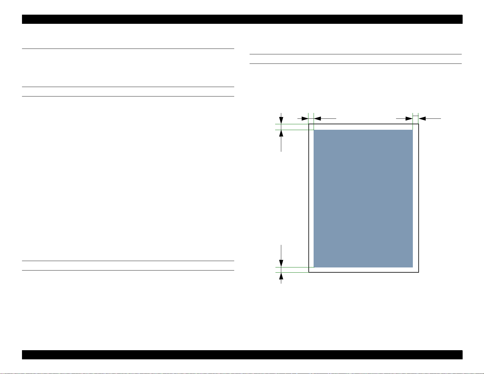
PRINTABLE AREA
Print Area: Area within margins of 4mm from ea ch sid e (See
Figure 1-1 below)
4mm4mm
Printable Area
Density R egulator: Developer Bias Variation System (can be
regulated by user)
Resolution: 600 dpi
4mm 4mm
PRINTING SPEED
Printing S peed: 8 ppm (A4/B5/A 5 Ve rtical Feed)
First Print: 19 seconds (A4 Vertical Fee d)
18.2 secon ds (B5 )
17.3 secon ds (A5 )
Figure 1-1. Printable Area
PRODUCT DESCRIPTION BASIC SPECIFICATIONS 10
Page 11
EPL-5700L/5700i Revision A
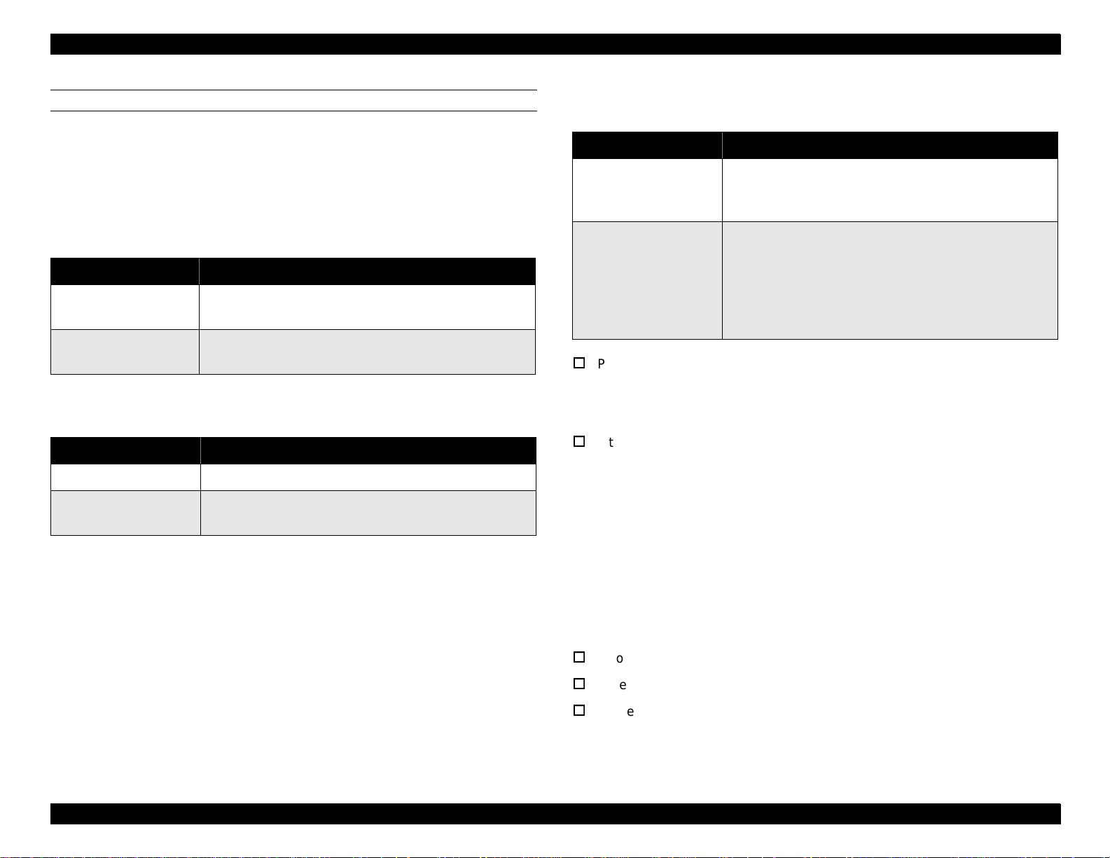
PAPER HANDLING
Paper Supply: 150-sheet C assette-like Multipurpose Tray
Man ual Feed Slot
Option al Cassette: 500-sheet A 4 Low er Cassette Unit
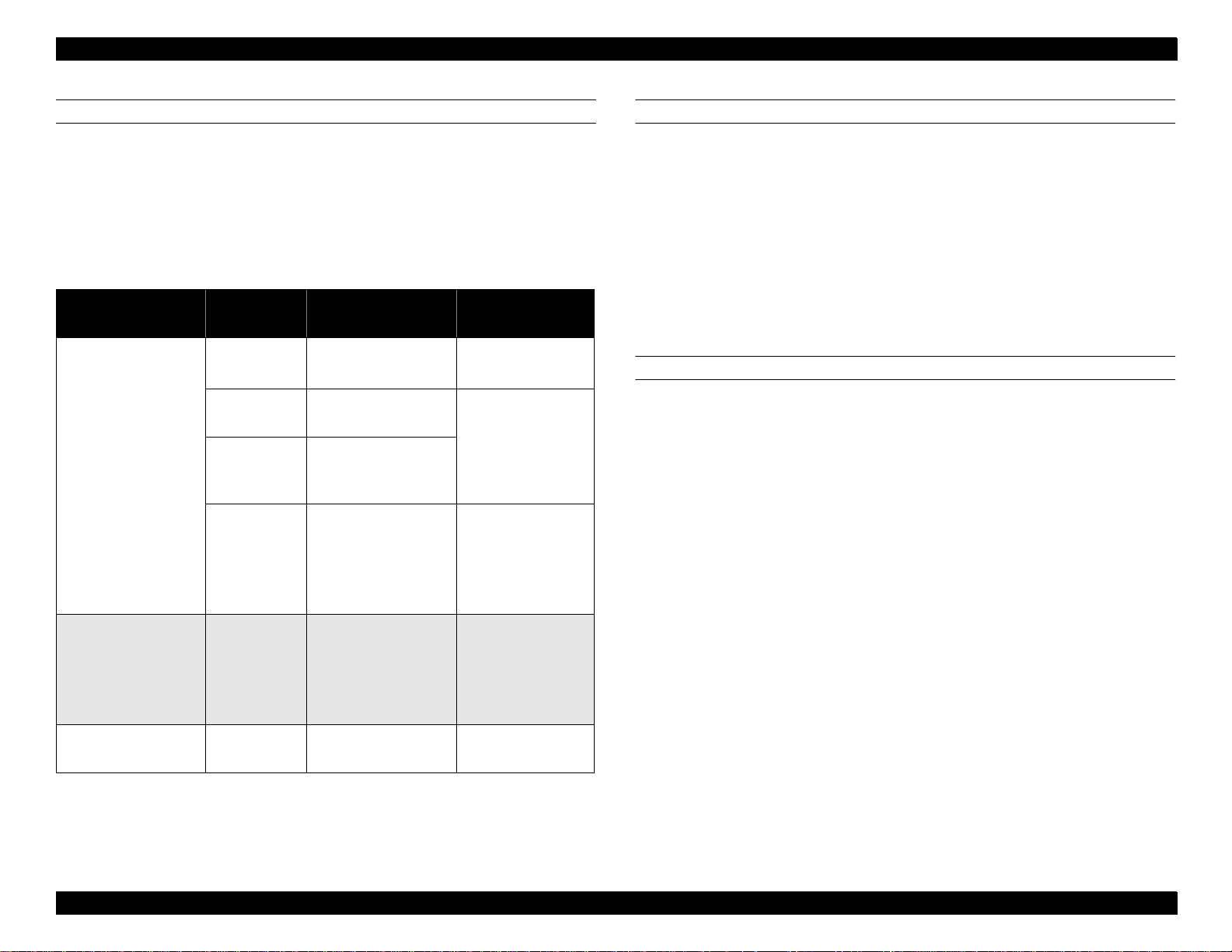
Table 1-1. Paper Handling
Paper Supply Capacity Paper Size
76.2 x 127 to
215.9 x 355.6mm
Japanese Official
Postcard
Japanese Official
Postcard (when
printing on back)
Envelope/Label
OHP/Thick Page
Multipurpose Tray
150 sheets
50 sheets
20 sheets
10 sheets
Permissible
Paper Thickness
60 to 90g/m
(16 to 24lb)
190g/m
Normal Paper:
60 to 90g/m
Thick Paper:
90 to 190g/m
Special Paper
CONSUMABLES
Name: ET Cartridge
Photoconductor Unit
Life: ET C artridge: Average of 3,000 sheets
OP C D rum : Average of 20,000 sheets
(at continuous printing on A4 page with p rint duty
of 5%)
2
CONTROLLER SPECIFICATIONS
CP U: 16bit, 64pin, max 25M H z, CISC,
2
TM P95C 001 (TOS HIBA)
RA M : Standard: 2M B (ED O )
2
O p tio n a l SIM M S lo t: 1
32M B, 16MB , 8MB , 4MB (ED O )
2
(A maximum of 13MB is valid.)
Manual Feed Slot
Lower Cassette
1 sheet
500 sheets A4
Paper Output: Face-down
Face-up (w hen an optional hopper is used)
100 x 148 to
215.9 x 355.6mm
Normal Paper:
60 to 90g/m
Thick Paper:
90 to 190g/m
Special Paper
Normal Paper:
60 to 90g/m
2
2
2
RO M : Program: 512Kbytes
Host Interface: Standard: Ce ntronics, B i-directiona l Parallel
IEEE-1284 nibble
ECP compliant
USB: Serial
(No slot for the optional I/F)
PRODUCT DESCRIPTION BASIC SPECIFICATIONS 11
Page 12

EPL-5700L/5700i Revision A
SOFTWARE SPECIFICATIONS
This printer is host-based, nam ely, the host comp uter (printer driver)
generates print im ages. Refer to the software guide for details.
ENVIRONMENTAL CONDITIONS
Tem peratu re (including expendable parts):
Operation: 10 to 35 °C
Storag e under normal conditions: 0 to 35 °C
Storag e under extrem e conditions: -20 to 40 °C
(1/30 of the total holding period)
Hum idity (including e xpendable parts):
Operation: 15 to 85% w ithout condensatio n
Storag e under normal conditions: 30 to 85%
Storag e under extrem e conditions: 10 to 95%
(1/30 of the total holding period)
AC Line Noise: Pulse Width: 50 to 1,000ns
Pulse Polarity: ±
Repeat: Non-simultan eous
Mo de: Common/N orm al
Voltage: 1KV
Parts can w ithstand up to 2KV withou t damage.
Instant Cutoff: DIP 100% (for standard voltage - 10%) for one
cy c le with n o rmal p rin t q ua lity .
E le ctro s ta t ic Dur a b ilit y : No h ardwa re er rors up to ± 10KV.
(No unrecoverable software errors)
Com ponen ts can withstand up to ± 15KV without
dam age.
Ru sh C urrent: 1/2 cycle, 50A or less
ELECTRICAL SPECIFICATIONS
Insulation Re sistance: 10M
or higher
Ω
Dielectric Strength: AC 1000V is applied for one m inute w ith no
Pow er Supply Voltage: 100 ± 10%
Pow er Supply Frequency: 50 to 60Hz ± 3Hz
Leakage Current: 0.25m A or less (100V m odel)
breakdowns (duratio n of one surge).
Standard Maximum Current: 6.3A
Pow er Consum ption: Maximu m : 580W
Average during continuous printin g:200W
Standby Mode (Heater On): 490W
Standby Mode (Heater Off): 15W
PRODUCT DESCRIPTION BASIC SPECIFICATIONS 12
Page 13

EPL-5700L/5700i Revision A
DIMENSIONS
Dimensions: Main Unit: 397mm (W) x 493m m (L) x 251m m (H)
W eight: Approx. 7 .5kg
RELIABILITY AND DURABILITY
Product Life: Approx. 1 80,000 printed pages or five years,
whichever com es first
MP BF : 25,000 sheets or more
MT BF: 3,000 hours (10 m onths) or m ore
Paper Feed Re liability (when usin g the recom mend ed paper under
normal conditions)
Jam R ate: 1/2000 or less (not including multiple pages)
Misfee d: 1/2000 or less
Multiple Page Fee d Rate: 1/500 or less
Paper W rinkling: 1/1000 or less
Paper Leading Edge Folds:1/1000 or less
(corner folds m ore than 1m m )
PRODUCT DESCRIPTION BASIC SPECIFICATIONS 13
Page 14
EPL-5700L/5700i Revision A
[
]
[
]
[
]
APPLICABLE CERTIFICATION STANDARDS AND REGURATIONS
The specifications of this engine m eet the certification standards and
regulations indicated below . There are cases in which the standards and
regulations apply differ e n tly to pr o d uc ts, in c lu ding th e controller, dependin g
on their destination.
Safety Standards
Table 1-2. Safety Standards
Model Name Applicable Certification
120V Model
200V Model
UL 1950
CSA 22.2 No.950
TÜV-GS (EN60950)
NEMKO (EN60950)
Safety Regulations
Table 1-3. Safety Regulations
Model Name Applicable Certification
120V Model FDA (NCDRH) Class 1
200V Model
TÜV-GS (EN60825)
NEMKO (EN60825)
EMC
Table 1-4. EMC
Model Name Applicable Certification
CNS 13438
100V Model
200V Model
Pow er Consum ption:
CISPR22 (Taiwan)
FCC Part15 Subpart B Class B/CSA C108.8 Class B
EC EMC Directive 89/336/PEC
EN55022 Class B
EN61000-3-2
EN61000-3-3
EN50082-1
AS 3548 (Australia)
In compliance with international E nergy Star
standards.
Others:
Toner: D oes not affect hum an body (in accordance with
OSHA, TSCA, EINECS and CSCL).
OP C: Does not affect hum an bod y (in accordance with
OSHA).
Ozone E m issions: C onform s to UL 478, 5th version.
Ma terials: Conforms to Swiss environmental protection laws
(does not include C dS).
Ozone: 0.02 ppm or less
Potential T oxicity: O PC , toner, and plastic parts are nontoxic.
Noise: Stand-by: 30 dB (A) or less
In operation : 47 .0 dB (A) o r less
PRODUCT DESCRIPTION BASIC SPECIFICATIONS 14
Page 15
EPL-5700L/5700i Revision A
1.3 PAPER SPECIFICATIONS
The types of paper which can be used with EP L-5700L/5700i are described
below.
PAPER TYPES
Normal Paper: P PC , recycled paper 6 0 to 90g/m2 (16 to 24lbs)
Special Paper: Labels, Japanese officia l p o s tc a rd s , OH P films,
color paper, thick paper (90 to 157g/m
DTP , and letterhead
The paper types listed below cannot be used with this
CAUTION
printer.
• Carbon paper, non-carbon paper, thermal transfer paper, impact
paper, and acidic paper.
• Paper which has been used with a thermal transfer or ink-jet
printer.
• Paper which is too thick or too thin.
• Wet (damp) paper.
• Paper to which a special coating has been applied, or colored
paper which has gone through surface processing.
• Paper whose surface is too smooth or too rough, or paper
whose texture is different on the front and back.
• Paper with holes for binders or perforations.
• Folded, curled, or damaged paper.
• Paper of irregular shape or not cut with right angles.
• Paper with labels that come off easily.
• Paper with glue, staples, or paper clips attached.
• Special ink-jet paper.
When using illustrated postcards, paper particles may
adhere to the paper feed roller and cause paper feed
difficulty. Therefore, it will be necessary for users to
perform cleaning as indicated in Chapter 6 “Maintenance”.
2
), special
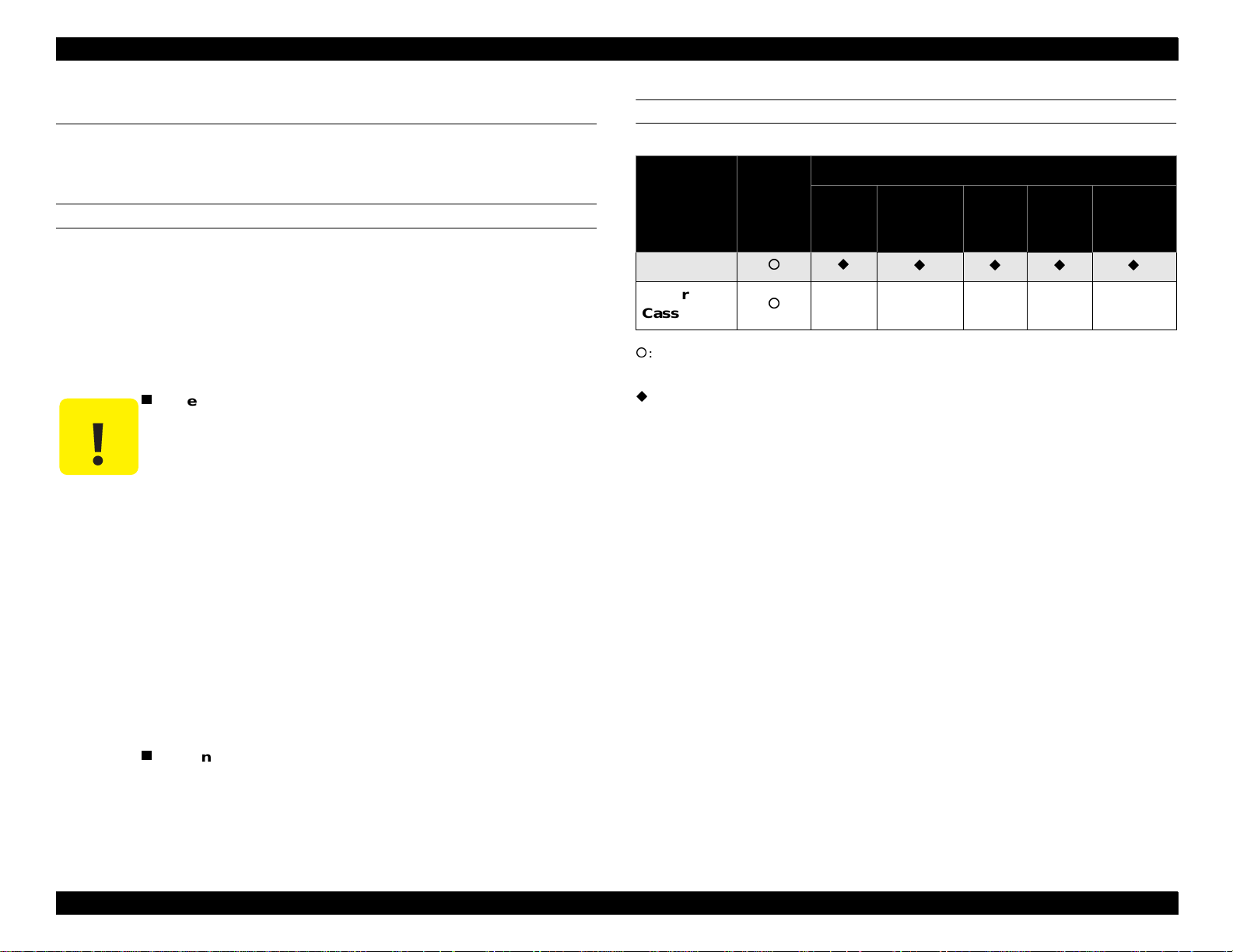
PAPER CLASSIFICATIONS
Table 1-5. Paper Classification
Special Paper
Paper
Supply
Paper Tray
Lower
Cassette
: Can guarantee paper feed reliability and image quality. However, this is limited to
generally used paper.
: Can print characters. However, this is limited to generally used paper.
X: Cannot feed.
Normal
Paper
Japanese
OHP
XXXXX
Official
Postcard
Label
Thick
Paper
Envelope
PRODUCT DESCRIPTION PAPER SPECIFICATIONS 15
Page 16
EPL-5700L/5700i Revision A
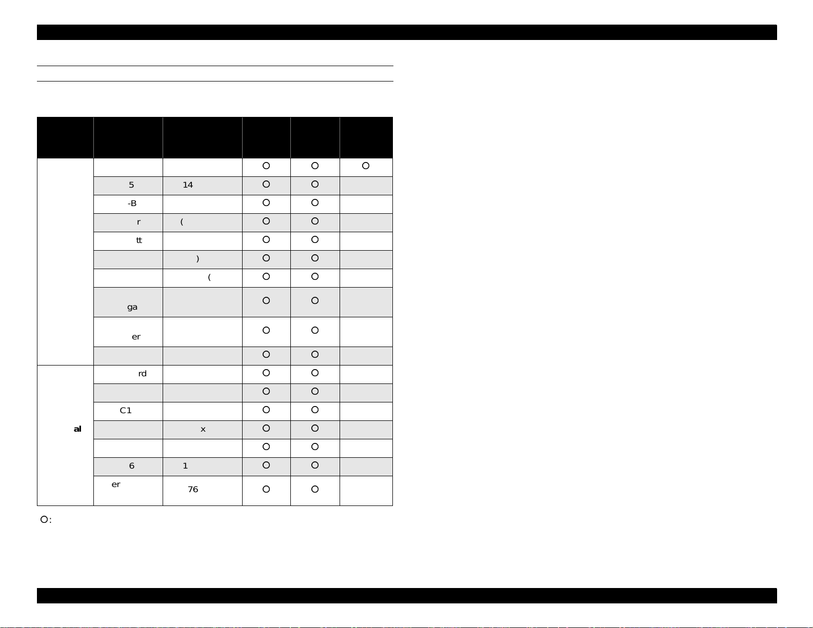
PAPER SIZE
Table 1-6. Paper Size
Paper
Type
Normal
Paper
Paper
A4 210 x 297
A5 148 x 210
JIS-B5 182 x 257
Letter (8.5) x (11)
Half Letter (5.5) x (8.5)
Legal (8.5) x (14)
EXE (7.25) x (10.5)
Government
Legal
Government
Letter
F4 210 x 330
Postcard 100 x 148
Monarch 98.43 x 190.5
C10 104.78 x 241.3
Size
mm (inch)
(8.5) x (13)
(8) x (10.5)
Paper
Tray
Manual
Feed Slot
Optional
Lower
Cassette
-
-
-
-
-
-
-
-
-
-
-
-
Special
Paper
DL 110 x 220
C5 162 x 229
C6 114 x 162
International-
B5
176 x 250
-
-
-
-
: Applicable
PRODUCT DESCRIPTION PAPER SPECIFICATIONS 16
Page 17
EPL-5700L/5700i Revision A
CHECK
POINT
1.4 PANEL OPERATION
1.4.1 Power Switch
Pow er Switch is located on the left rear side of the printer, and it controls
power on/off.
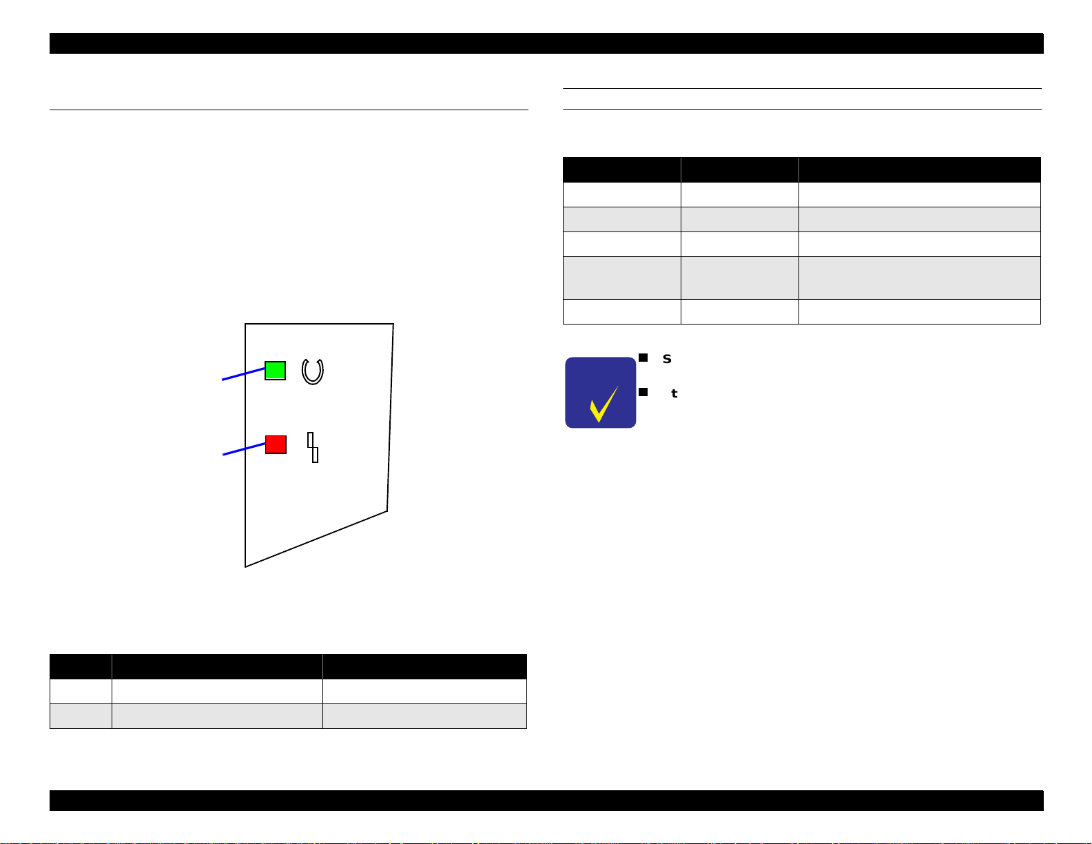
1.4.2 Control Panel
Control Panel is located at the righ t front edge of the printer, and it consists
of two LED lamps.
1
2
FLASHING LED
Table 1-8. Meaning of Flashing LED Lamps
Ready Lamps Error Lamp Meaning
OFF OFF Power OFF.
ON OFF Possible to print.
Flashing OFF Warming up, receiving data
OFF Flashing
OFF ON Service call error
Since the EPL-5700L/5700i is a host-based printer, printer
settings cannot be made on the control panel.
Status sheet can be printed from the printer driver.
Recoverable error
(including paper out)
Figure 1-2. Control Panel
Table 1-7. LED Lamps
Name Color
1 Ready Lamp Green
2 Error Lamp Red
PRODUCT DESCRIPTION PANEL OPERATION 17
Page 18

EPL-5700L/5700i Revision A
1.5 RAM EXPANSION
If m em ory shortage occurs, the prin ter outputs a m isprint and an error
message a ppears on the host screen. In such a case, it is necessary to
install expansion m em ory RAM (RA M SIMM).
The recommended RAM capacity for conditions of use are as shown below.
(However, this does not include im ages w ith extremely poor com pression
ratio.)
Table 1-9. Recommended RAM Capacity
• MicroGray printing may not be possible at 600 dpi.
No RAM Expansion
4MB Expansion Printing is possible under all conditions
• For a host with slow transfer speed, normal 600
dpi printing may not be possible.
CAUTION
The memory shown below cannot be used with the EPL5700L/5700i. The CPU of the printer is 16bit, but the
following memory is not designed to allow access at 16bit.
SAMSUNG KMM5328104
PRODUCT DESCRIPTION RAM EXPANSION 18
Page 19

EPL-5700L/5700i Revision A
1.6 OPTIONS AND CONSUMABLE PRODUCTS
Option al low er cassette unit and printer cables for EP L-5700L/5700i are th e
same a s options for E PL-5700.
PRODUCT DESCRIPTION OPTIONS AND CONSUMABLE PRODUCTS 19
Page 20

OPERATING PRINCIPLES
Page 21

EPL-5700L/5700i Revision A
2.1 OPERATING PRINCIPLES OF MECHANISM
The EP L-5700L/5700i adopts the same mechanism as used in the previous
mod el. Re fer to the E PL -5700 Service M anual for the detailed operating
principles of each m echanism.
OPERATING PRINCIPLES OPERATING PRINCIPLES OF MECHANISM 21
Page 22

EPL-5700L/5700i Revision A
2.2 ELECTRIC CIRCUIT
Since the E lectric Circuit of this printer is basically the same a s th at of E PL5700, this section explains only about the Main Control Board and its
related parts.
2.2.1 Operating Principles of Controller
The C29 2 M ain Board, w hich functions as a controller of the printe r,
consists of the M ain Controller and the Engine Contro lle r.
Main Controller
TUSB
DRAM
RAMSIMM (CN1)
CPU
JP1
SLC
1284DRIVER
USB I/F
Parallel I/F
The M ain Controller processes print data sent from the host computer and
generates video signal.
The Engine Controller receives video signal from the Main Controller and
drives the engine to print.
FUNCTIONS OF THE MAIN CONTROLLER
Com m unication with the host com puter (receiving print data and
sendin g status).
Processing the print data (a nalyzing command and generating vide o
signal).
Sending the video signa l to the Engin e Controller.
Mon itoring panel or switch conditions.
FUNCTIONS OF THE ENGINE CONTROLLER
Receiving the video signal and sending engine status.
Mon itoring sensors.
Controlling the optional lower cassette.
Block diagram of the C292 Main Board and function of e ach device are
shown on the following page.
ROM
Video (CN3)
CPU
Engine Controller
Figure 2-1. C292 Main Board
OPERATING PRINCIPLES ELECTRIC CIRCUIT 22
Page 23

DRAM
16Mb*16
42pin
(IC3)
ROM
4Mb*16
40pin
(IC2)
16
MA10-0
16
CPU
TM95C001
64pin
(IC1)
+22.9982MHz
-22.9982MHz
MCLKOX
MCLKIN
A23-1
22.9982MHz
Reset IC
(IC6)
Reset Signal
Reg.
PQ3DZ13
CN1
RAMSIMM
72pin
CN5
USB
4pin
CN2
Parallel
36pin
D15-0
TSUB
64pin
(5/3.3V)
E05B69NA
(IC21)
48MHz
LV161284
48pin
(IC7)
Engine
Controller
1616
3.3V
SLC
208pin
(5/3.3V)
E05B68NA
(IC5)
3.3V
5V
Serial
EEPROM
1kb
(IC8)
CN207
Figure 2-2. Block Diagram of the C292 Main Board
EPL-5700L/5700i Revision A
CN3
OPERATING PRINCIPLES ELECTRIC CIRCUIT 23
Page 24

EPL-5700L/5700i Revision A
Name Location Functions
CPU
TM95C001
ASIC (SCL)
E05B68NB
ASIC (TUSB)
E05B69NA
Table 2-1. C292 Main Board - Main Controller
16bit CISC-CPU driven at clock frequency
IC1
IC5
IC21
25MHz.
Package: 64pin, QFP
Power supply voltage: 5V Single
This ASIC controls the following:
• Memory (RAM/ROM)
• DMA (Video, I/O)
• RIT (Resolution Improvement Tech.) / PGI
(Photo Grade Improvement) function.
• Video I/F (communication with the Engine
Controller)
• Panel LED
Package: 208 pin, QFP
Power supply voltage: 5V/3.3V
Operation frequency: DMAC max 25MHz
PIF max 25MHz
DCMP max 60MHz
RIT max 100MHz
Controls USB I/F.
Package: 64 pin, QFP
Power supply voltage: 5V/3.3V
Operation frequency: max 48MHz
Table 2-1. C292 Main Board - Main Controller (continued)
Name Location Functions
USB I/F CH5 USB connector with the host PC
Parallel I/F CH2 Parallel connector with the host PC
Control Panel I/F CN4 LED-control connector
Table 2-2. C292 Main Board - Engine Controller
Name Location Functions
CPU
M38073E4FS
Motor Drive IC
TEA3718SDP
IC201 Controls the engine.
IC204/
IC205
Drives the main motor.
TTL
SN74LV162184DGGR
DRAM
M5M418165CJ-6
ROM
HN27C4000G-10
RAMSIMM CN1 72 pin, memory expansion connector
IC7
IC3
IC2
1284 driver. Receives / sends parallel I/F
signal.
Power supply voltage: 5V
One EDO with 16Mb, 16bit, 60ns is mounted.
Operates as standard memory.
4Mb, 16bit, and 40pin module. Stores the
control program.
OPERATING PRINCIPLES ELECTRIC CIRCUIT 24
Page 25

TROUBLESHOOTING
Page 26

EPL-5700L/5700i Revision A
3.1 OVERVIEW
3.1.1 Overview
Since the E PL-5700L/5700i is a host-based printer, m ost problems can be
solved by operating “EPSON Printer W indow !3” on the host computer.
When an error occurs, “EPSON Printer Window !3” appears on the host
screen as a pop-up w indow, which provides detailed instructions on ho w to
handle each error. M ost of the errors will be cleared by following the
instructions of the pop-up wind ow.
Also refer to the section “Troubleshooting” of the E PL-5700L/5700i U ser’s
Guide, which gives instructions for solvin g general problems.
3.1.2 Electric Check Point
Refer to 3.2 of the EP L-5700 Service M anual.
TROUBLESHOOTING OVERVIEW 26
Page 27

EPL-5700L/5700i Revision A
3.2 HANDLING SERVICE CALL ERRORS
This section describ es various conditions which may cause fatal errors, and
provides remedies for such errors.
3.2.1 Service Call Error Conditions
Note th at the following operations will r e s u l t in t h e Ser v ic e Cal l E r rors
w ith o u t fa il.
Bringing up the BIOS settings screen with the printer power on.
Turning on - off - on the printer while prin ting.
Turning on “Apple Talk” w hile using EPSON LINK3.
Using the printer driver other than designated for the EP L-5700L/5700i.
3.2.2 Error LED Lamp
Ready Lam p: O FF
Error Lam p: ON (Red)
3.2.3 Error Code Display and Remedies
In most Service Call Error cases, the p rinter recovers from the error if it is
turned off and on again. H ow ever, in the case w here the printer does not
recover from the erro r even after the above operation, check the Service
Call Error Code a nd take appropriate m easures as shown in Table 3-1.
SERVICE CALL ERROR CODE DISPLAY
If a Service Call Error occurs and “EPSON Printer W indow !3” pops up
on the screen, press C trl+Shift+Enter together to display the error code.
Table 3-1. Service Call Error Codes
Service Call Error Code Error Description Remedy
I0001 Protocol Error Replace th e Main Board.
C1999 Video Error Replace the Main Board.
C1999 Data Expansion Error Replace the Main Board.
C1000
C1200
C2000 Software Error
Win Mac
E0003 E2000 Abnormal Fusing
E0006
E0009 Abnormal Laser
E0014
Standard RAM Check
Error
EEPROM Access
Error
Abnormal Polygon
Motor
Communication Error
with Engine
Replace the Main Board.
• Initialize EEPROM.
• Replace the Main
Board.
• Reboot the host PC.
• Reinstall the driver.
• Replace the Main
Board.
Refer to 3.4.2.3 of the
EPL-5700 Service
Manual.
Refer to 3.4.2.2 of the
EPL-5700 Service
Manual.
Refer to 3.4.2.1 of the
EPL-5700 Service
Manual.
• Replace the engine.
• Replace the Main
Board.
CAUTION
This function should not be made open to users.
TROUBLESHOOTING HANDLING SERVICE CALL ERRORS 27
Page 28

EPL-5700L/5700i Revision A
RESETTING EEPROM
1. Open the printer’s “Properties” (or “Document Defaults” for Windows
NT4.0), and select “Optional Settings”.
2. Click the left button of the mouse while pr essing
ALT+CTRL+SHIFT+W, and the dialogue box shown below will
appear.
Cancel
Figure 3-1. Reset the EEPROM
3. Click “OK”, and EEPROM will be reset.
CAUTION
The above function should not be made open to users.
TROUBLESHOOTING HANDLING SERVICE CALL ERRORS 28
Page 29

DISASSEMBLY AND ASSEMBLY
Page 30

EPL-5700L/5700i Revision A
4.1 OVERVIEW
The following parts and units of the EP L-5700L/5700i are different from
those of EP L-5700.
Control Panel
Top cover securing method
M a in Boa r d
USB I/F
The other m echanism and exterior parts are exactly the sam e as used in
EPL-5700. Therefore, this chap ter contains the disassem bly and assembly
procedures only for the parts and units mentioned above. Refer to the EP L5700 Service M an ual for other item s.
DISASSEMBLY AND ASSEMBLY OVERVIEW 30
Page 31

EPL-5700L/5700i Revision A
4.2 DISASSEMBLY AND ASSEMBLY
4.2.1 Control Panel Removal
Unlike the previo us m odel, the EPL-5700L/5700i has only tw o LED lamps
and no other functions on the control panel. However, exterior of the panel
is exactly the same a s the previous m odel, a nd so is the way the panel is
fixed on the printer. Refer to the EPL-5700 S ervice M anual (pp. 4 - 10) for
the Control Panel disassem bly and assembly procedures.
Control Panel
Hooks
Front Cover
Figure 4-2. Control Panel Removal (No. 2)
Harness to Main Board
4.2.2 Top Cover Removal
1. Remove the right cover (See section 4.2.2 of the EPL-5700 Service
Manual).
2. Remove the control panel (See section 4.2.1 of this manual).
3. Remove the front cover (See section 4.2.7 of the EPL-5700 Service
Manual).
Fixing Screws (CS M3X8)
Figure 4-1. Control Panel Removal (No. 1)
DISASSEMBLY AND ASSEMBLY DISASSEMBLY AND ASSEMBLY 31
4. Remove the left cover (See section 4.2. 10 of the EPL-5700 Service
Manual).
Page 32

EPL-5700L/5700i Revision A
5. Remove a screw (CS M3x8) and a plate loca ted on the upper part o f
the shield cover of the Main Control Board (see Figure 4-3 below).
6. Push both left and right hinges of the top cover ou tward as shown i n
Figure 4-4, and remove the top cover.
Hinges
Top Cover
Plate
Figure 4-3. Plate Removal
Screw (CS M3X8)
Figure 4-4. Top Cover Removal
DISASSEMBLY AND ASSEMBLY DISASSEMBLY AND ASSEMBLY 32
Page 33

EPL-5700L/5700i Revision A
4.2.3 Main Control Board Removal
1. Remove the right cover (See secti on 4.2.2 of the EPL-5700 Service
Manual).
2. Remove the control panel (See section 4.2.1 of this manual).
3. Remove the front cover (See section 4.2.7 of the EPL-5700 Servi ce
Manual).
4. Remove 10 screws (CS M3x8) securing the shield cover of the Main
Control Board, and remove the shield cover (See section 4.2.9 of
the EPL-5700 Service Manual).
5. Remove the harnesses which are connected to the connector on the
Main Control Board.
6. Remove 10 screws (CS M3x8) securing the Main Control Board on
the printer (See section 4.2.9 of the EPL-5700 Service Manual).
7. Remove a fixing screw for USB interface (CS M3x6) and two fixing
screws for parallel interface (CP M3x6), and remove the board.
Main Board Fixing Screws
USB Connector Fixing Screw
Parallel
Connector
Fixing
Screws
Figure 4-5. Main Control Board Removal
DISASSEMBLY AND ASSEMBLY DISASSEMBLY AND ASSEMBLY 33
Page 34

ADJUSTMENTS
Page 35

EPL-5700L/5700i Revision A
Refer to the EPL-5700 Service M an ual, Chapter 5 for adjustment
procedures.
ADJUSTMENTS 35
Page 36

MAINTENANCE
Page 37

EPL-5700L/5700i Revision A
Refer to the EPL-5700 Service M an ual, Chapter 6 for m aintenance
procedures.
MAINTENANCE 37
Page 38

APPENDIX
Page 39

EPL-5700L/5700i Revision A
7.1 CONNECTOR PIN ASSIGNMENTS
The figure below show s interconnections with the Main Board, and the table
on the right show s function of each connector.
Heater
Lamp
RAM
SIMM
Parallel
I/F
USB I/F
Control
Panel
Power Board
CN2
CN1
CN3
Interlock
Switch
Lower
Cassette
C292 Main Board
CN3
CN1
CN2
CN5
CN4
CN207
CN211
CN202
CN203
CN204
CN205
CN206
CN208
CN209
CN210
CN212
Fusing
Thermister
Paper Feed
Solenoid
High
Voltage
Board
Print
Head
Main
Motor
Paper
Eject
Sensor
Polygon
Motor
Paper
Feed
Sensor
Paper
Empty
Sensor
Table 7-1. Connector List
Board Connector Function Reference
EPL-5700 Service
C292 MAIN
High Voltage
Board
Power
Board
CN1 For Expanded RAMSIMM, 72 pin
CN2 Parallel Interface, 36 pin
CN3 Video (not used) CN4 Control Panel (LED Control) -
CN5 USB Interface Table 7-2
CN202 Fusing Thermister CN203 Paper Feed Solenoid Control CN204 High Voltage Board CN205 Print Head Control CN206 Main Motor Control CN207 Power Board CN208 Paper Eject Sensor CN209 Polygon Motor Control CN210 Paper Feed Sensor CN211 Lower Cassette Control CN212 Paper Empty Sensor -
CN1 Main Control Board -
CN1 Main Control Board -
CN2 Fusing Heater Lamp Control -
CN3 Interlock Switch Control -
Manual, Table 7-5
and 7-7
EPL-5700 Service
Manual, Table 7-8
Figure 7-1. Interconnection with the Main Board
APPENDIX CONNECTOR PIN ASSIGNMENTS 39
Page 40

EPL-5700L/5700i Revision A
Table 7-2. Connector CN5 Pin
No. Signal Name Direction Function
1 POWER - Cable Power Supply
2 D- Bi-directional Data Signal
3 D+ Bi-directional Data Signal
4 GND - Ground
APPENDIX CONNECTOR PIN ASSIGNMENTS 40
Page 41

EPL-5700L/5700i Revision A
7.2 CIRCUIT BOARD COMPONENT LAYOUT
Figure 7-2. C292 Main Control Board Component Layout
APPENDIX CIRCUIT BOARD COMPONENT LAYOUT 41
Page 42

EPL-5700L/5700i Revision A
7.3 EXPLODED DIAGRAMS & ASP LIST
7.3.1 Exploded Diagrams
Refer to the EPL-5700 Service M an ual 7.3 “Explo ded Diagram” as the
exterior and mechanism of the EPL-5700L/5700i are basically the sam e.
T h e o n ly d iffe re n c e with th e p re v io u s model is “PLA TE”, which has been
newly added to (6) FRAME S I, and its exploded diagrams are shown on the
following pages.
APPENDIX EXPLODED DIAGRAMS & ASP LIST 42
Page 43

EPL-5700L/5700i Revision A
APPENDIX EXPLODED DIAGRAMS & ASP LIST 43
Page 44

EPL-5700L/5700i Revision A
APPENDIX EXPLODED DIAGRAMS & ASP LIST 44
Page 45

EPL-5700L/5700i Revision A
APPENDIX EXPLODED DIAGRAMS & ASP LIST 45
Page 46

EPL-5700L/5700i Revision A
APPENDIX EXPLODED DIAGRAMS & ASP LIST 46
Page 47

EPL-5700L/5700i Revision A
APPENDIX EXPLODED DIAGRAMS & ASP LIST 47
Page 48

EPL-5700L/5700i Revision A
APPENDIX EXPLODED DIAGRAMS & ASP LIST 48
Page 49

EPL-5700L/5700i Revision A
APPENDIX EXPLODED DIAGRAMS & ASP LIST 49
Page 50

EPL-5700L/5700i Revision A
7.3.2 ASP List
Table 7-3. Parts List
Diagram No. Parts Code Parts Name
1-01 1040689 TOP COVER ASSY.
1-03 1048628 LEFT COVER
1-05 1048629 FRONT COVER
1-06 1040693 TRAY
1-07 1040697 CASSETTE BODY
1-08 1013911 GEAR 14T
1-09 1040698 TABLE
1-10 1040699 GUIDE
1-11 1040700 GUIDE
1-12 1040694 RIGHT COVER
1-13 1040701 COVER
1-14 1040695 COVER
1-15 1040696 TRAY ASSY.
1-16 1040702 SHEET
1-17 1050576 LOGO PLATE
450 2031327 PANEL
200 2032935 BOARD ASSY., MAIN
2-01 1040703 GUIDE
2-02 1048622 ROLLER
2-03 1048624 GUIDE LEVER
2-04 1040706 GEAR ASSY.
2-05 1040709 TORSION SPRING
2-06 1040710 COVER
Table 7-3. Parts List (continued)
Diagram No. Parts Code Parts Name
2-07 1040711 ROCK LEVER
2-08 1040712 PLATE
3-01 1021636 BUSHING
3-02 1040714 CAM
3-03 1040715 ROLL
3-04 1048613 ROLLER
3-05 1040717 ROLLER
3-06 1040718 HOLDER
3-07 1040719 PRESSURE SPRING
3-08 1040720 JOINT
3-09 1048612 BUSHING
3-10 1040722 GEAR 18T
3-11 1048614 SHAFT
3-12 1040724 GEAR 36/54T
3-13 1040725 GEAR 36T
3-14 1040726 SHOULDER SCREW
3-15 2027738 SOLENOID
3-16 1040727 TORSION SPRING
3-17 1040728 PLATE
3-18 1040729 PLATE
3-19 1014684 PIN
3-20 1040730 LEVER
3-21 1040731 TORSION SPRING
3-22 1040732 ARM
3-23 1040733 SEPARATED PAD
APPENDIX EXPLODED DIAGRAMS & ASP LIST 50
Page 51

EPL-5700L/5700i Revision A
Table 7-3. Parts List (continued)
Diagram No. Parts Code Parts Name
3-24 1040734 PRESSURE SPRING
3-25 2027737 PAPER PICK UNIT
4-01 1040801 HOLDER
4-02 1040802 GEAR 36T
4-03 1040803 BUSHING
4-04 1040804 FUSING ROLLER-FNT
4-05 2028491 TUBE LAMP (H1 120V)
4-06 1040805 FUSING ROLLER-RR
4-07 1040806 BUSHING
4-08 1040807 PRESSURE SPRING
4-09 1040808 GUIDE
4-10 2027762 HARNESS
4-11 2027763 HARNESS
4-12 2027764 PHOTO INTERRUPTER (PS3)
4-13 2027765 ACTUATOR
Table 7-3. Parts List (continued)
Diagram No. Parts Code Parts Name
4-28 1048616 HOLDER L
4-29 1048617 HOLDER R
4-30 1048618 STOPPER L
4-31 1048619 STOPPER R
4-32 1013954 SEPARATOR ROLL
5-01 1048630 FRAME
5-04 2027740 MOTOR (M1)
5-05 1040738 GEAR 40T
5-06 1040739 GEAR 18/50T
5-07 1040740 GEAR 20/44T
5-08 1040741 GEAR 20/52T
5-09 1040742 GEAR 24/30T
5-10 1040743 GEAR 20/48T
5-11 1040744 GEAR 20/32T
5-12 1040745 GEAR 17/42T
4-14 1040809 BUSHING
4-15 1040810 SEPARATOR
4-16 1040811 TERMINAL
4-17 2027766 THERMISTOR (TH1)
4-18 2027767 THERMOSTAT (TS1)
4-19 1040813 HOLDER
4-20 1048620 GUIDE
4-21 1040815 SHEET
4-22 1048615 HOUSING ASSY.
4-23 2028489 FUSING UNIT (120V)
5-13 1040746 GEAR 26T
5-14 1040747 GEAR 21/50T
5-15 1040748 GEAR 17T
5-16 1040749 GEAR 27T
5-17 1040750 GEAR 18/42T
5-18 1040752 GEAR 17/25T
5-19 1040753 GEAR 21/56T
5-20 1040754 GEAR 20T
5-21 1040755 GEAR
5-22 1040756 GEAR 22/43T
APPENDIX EXPLODED DIAGRAMS & ASP LIST 51
Page 52

EPL-5700L/5700i Revision A
Table 7-3. Parts List (continued)
Diagram No. Parts Code Parts Name
5-23 2027744 PWB-HV
5-24 1040757 PLATE
5-25 2027745 HARNESS
5-26 2027746 HARNESS
5-27 2027747 SWITCH (PS2)
5-28 1040758 PRESSURE SPRING
5-29 1040759 GUIDE
5-30 1040760 GUIDE ASSY.
5-31 1040761 GEAR 21T
5-32 1040762 BUSHING
5-33 1040763 ROLLER
5-34 1040764 GUIDE
5-35 1040765 BUSHING
5-36 1040766 BUSHING
5-37 1040767 PRESSURE SPRING
Table 7-3. Parts List (continued)
Diagram No. Parts Code Parts Name
6-06 1048621 RUBBER FOOT
6-07 1040775 PORYESTER FILM
6-08 1040776 GUIDE PLATE
6-09 2027751 HARNESS
6-10 2032079 SWITCH
6-12 1031615 SHOULDER SCREW
6-13 2027754 HARNESS
6-15 1040779 COVER
6-16 1040780 BRACKET
6-17 1040782 GROUND PLATE
6-18 1040783 COVER
6-19 1040784 PLATE
6-20 1040785 WASHER
6-21 2027757 PWB SUPPORT 6.35H
6-22 2027758 IC
5-38 1040768 PORYESTER FILM
5-39 1040769 TORSION SPRING
5-40 2027748 HARNESS
5-41 2027739 DRIVE UNIT
5-42 2027743 TRANSFER UNIT
6-01 1040770 COVER
6-02 2032076 HARNESS
6-03 2027750 SWITCH (PE1)
6-04 1040771 BRACKET
6-05 1040772 HOLDER
6-25 1042729 PLATE
7-01 1040786 GUIDE
7-02 2030662 PWB-PU (PU1)
7-03 2013598 POWER CORD 120V
7-04 1040787 BRACKET
7-05 1040788 GUIDE PLATE
7-06 1040789 GUIDE PLATE
7-07 1040790 SHEET
7-08 1040791 SHEET
7-09 1040792 LIFTING PLATE
APPENDIX EXPLODED DIAGRAMS & ASP LIST 52
Page 53

EPL-5700L/5700i Revision A
Table 7-3. Parts List (continued)
Diagram No. Parts Code Parts Name
7-10 1048627 HOLDER
7-11 1013911 GEAR 14T
7-12 2027759 PRINT HEAD UNIT
7-13 1040794 HOLDER
7-14 1040795 TORSION SPRING
7-15 1040796 WIRING SADDLE 18.5
7-16 1015333 EDGE COVER 8.5H
7-17 1004683 EDGE COVER 15H
APPENDIX EXPLODED DIAGRAMS & ASP LIST 53
Page 54

EPL-5700L/5700i Revision A
7.4 CIRCUIT DIAGRAM
Circuit diagram s of the M ain Control Board is shown on the follow ing pages.
APPENDIX CIRCUIT DIAGRAM 54
Page 55

Page 56

 Loading...