

Page 1
EPSON TER M INAL PR INTER
EPL-5500
SERVICE MANUAL
EPSON
4005431
Page 2

- ii -
Page 3

NOTICE
All rights reserved. Reproduction of any part of this manual in any form whatsoever without SEIKO
EPSON’s express written permission is forbidden.
The contents of this manual are subjects to change without notice.
All efforts have been made to ensure the accuracy of the contents of this manual. However, should
any errors be detected, SEIKO EPSON would greatly appreciate being informed of them.
The above not withstandi ng SEIKO EPSON can assume no responsibil ity for any error s in this
manual or the consequence thereof.
Epson is a registered trademark of Seiko Epson Corporation.
General N ot ice:
be trademarks of their respective campanies.
Other product names used herein are for ident ication purposes only and may
Copyright © 1995 by SEIKO EPSON CORPORATION Nagano, Japan
- i -
Page 4

PRECAUTIONS
Precautionary not ati ons throughout t he t ext ar e c at egor ized relative to 1) personal injury and 2)
damage to equipment.
DANGER
WARN ING
The precautionary measures itemized below should always be observed when performing repair/
maintenance procedures.
Signals a precautio n which, if ignored, could result in seri ous or fatal personal injur y.
Great ca ution s hould be exercised i n performing procedures pr eceded by DANGER
Headi ngs.
Signals a precaution which , if ignored, could result in damage to equipment.
DANGER
1. ALWAY S D ISCON NECT T HE PRODU CT FROM B OT H THE P OWER SO URCE AN D PERI PHERAL DEVICES PERFORMING ANY MAINTENANCE OR REPAIR PROCEDURE.
2. NO WORK SHOULD BE PERFORMED ON THE UNIT BY PERSONS UNFAMILIAR WITH
BASIC SAFETY MEASURES AS DICTATED FOR ALL ELECTRONICS TECHNICI ANS IN
THEIR LINE OF WO RK.
3. WHEN PERFORMING TESTING AS DICTATED WITHIN THIS MANUAL, DO NOT CONNECT
THE UNI T TO A POW ER SOU RCE UNTIL IN STR UCTED TO DO SO. WHEN THE PO WER
SUPPLY CABLE MUST BE CONNECTED, USE EXTREME CAUTION IN WORKING ON
POWE R SUPPLY AND OTHER EL ECTRONI C COMPONENTS.
WAR NING
1. REPAIRS ON EPSON PRODUCT SHOULD BE PERFORM ED ONLY BY AN EPSON CERTIFIED REPAIR T ECHNICI AN.
2. MAKE C ERTAIN THAT THE SOURCE V OL TAGE IS THE SAME AS THE RAT ED VOLTAGE,
LISTED ON THE SERIAL NUMBER/RATING PLATE. IF THE EPSON PRODUCT HAS A
PRIMA RY AC R ATI NG D IFFE RENT FRO M AV AILA BLE POW ER SOUR CE , DO NOT C ON NECT IT TO THE POWER SOURCE.
3. ALWAY S VERIFY THAT THE EPSON PRO DUCT HAS BEEN DISCONN E CTED FROM T HE
POWER SOURCE BEFORE REMOVING OR REPLACING PRINTED CIRCUIT BOARDS
AND/O R INDIVI DUAL CHI PS.
4. IN ORDER TO PROTECT SENSITIVE MICROPROCESSORS AND CIRCUITRY, USE STATIC
DISCH ARGE EQ UIPM ENT, S UC H AS A NTI -STAT IC WRI ST S TRAPS, WH EN ACCES SIN G
INTERNAL COMPONENTS.
5. REPLACE MALFUNCTIONING COMPONENTS ONLY WITH THOSE COMPONENTS BY THE
MANUFACTURE; INTRODUCTION OF SECOND-SOURCE ICs OR OTHER NONAPPROVED
COMPONENTS MAY DAMAGE THE PRODUCT AND VOID ANY APPLICABLE EPSON WARRANTY.
- ii -
Page 5

SAFET Y INFORMATION
This printer is a page printer which operates by means of a laser. There is no possibility of danger from
the laser, provided the printer is operated according to the instructions in this manual provided.
Since radiation em itted by the laser is completely confined with in protective housings, the laser beam
cannot escape from the machine during any phase of user operation.
For United States Users;
[Laser Safety]
This printer is certified as a Class 1 Laser product under the U.S. Department of Health
and Human Services (DHHS) Radiation Performance Standard according to the Radiation Control for Healt h and Safety Act of 1968. Thi s means that the printer does not
produce hazardous laser radiation.
[CDRH Reg u lations ]
The Center for Devices and Radiologica l Health (CDRH) of the U.S. Food a nd Drug
Administr ation implemented regul ati ons for laser product s on August 2, 1976. Compliance is mandatory for products marketed in the United States. The label shown below
indicates compliance with the CDRH regulations and must be at tached to laser products
marketed in the United States.
WARNING : Use of controls, adjustments or performance of procedures other
than those specified in this manual may result in hazardous radiation exposure.
[Internal Laser Radiation]
Maximum Radiation Power: 5.0 × 10⁻⁴ (W)
Wave Length: 790 ± 20 nm
This is a Class IIIb Laser Diode Assay that has an invisi ble la ser beam. The print head
unit is NOT A FIELD SERVICE ITEM. Therefore, the print head unit should not be opened
under any circumstances .
For Other Countr ies Users;
WARNING: Use of controls, adj ustments or performance of pro cedures other
than those specified in this manual may result in hazardous radiation exposure.
This is a semiconductor laser. The maximum power of the laser diode is 5.0 ×
10-4 W and the wavelength is 790 ± 20 nm.
For Denmark Users;
ADVARSEL
Usynlig laserstr åling ved åbning , når sikkerhedsafbrydere er ude af funktion.
Undgå udsættelse for stråling.
Klasse 1 laser produkt der opfylder IEC825 sikkerheds kravene.
- iii -
Page 6
For Finland , Sweden User s;
VAROITUS
Laitteen käyttäminen muulla kuin tässä käyttöohjeessa mainitulla tavalla saattaa altistaa käyttäjän turvallisuusluokan 1 ylittävälle näkymättömälle lasersäteiylle.
VARNING
Om apparaten används på annat sätt än i denna bruksanvisning specificerats,
kan användaren utsättas för osynlig laserstrålning, som överskrider gränsen för
laser klass 1.
For Finland , Sweden Ser vice Peop le
VAROITUS
Avattaessa ja suojalukitus ohitettaessa olet alttiina näkymättömälle lasersäteilylle. Älä katso säteeseen.
VARNING
Osynlig laserstrålning när denna del är öppnad och spärren är urkopplad.
Betrakta ej strålen.
For Norway Users;
ADVARSEL
Dersom apparat et brukes på anne n m åte enn s pesi fi sert i denne br uksanv isning, kan brukeren utsettes for unsynlig laserstråling som overskrider grensen
for laser klasse 1.
Dette er en halvleder laser. Maksimal effeckt til laserdiode er 5.0 × 10⁻⁴ W og
bølgelengde er 790 ± 20 nm.
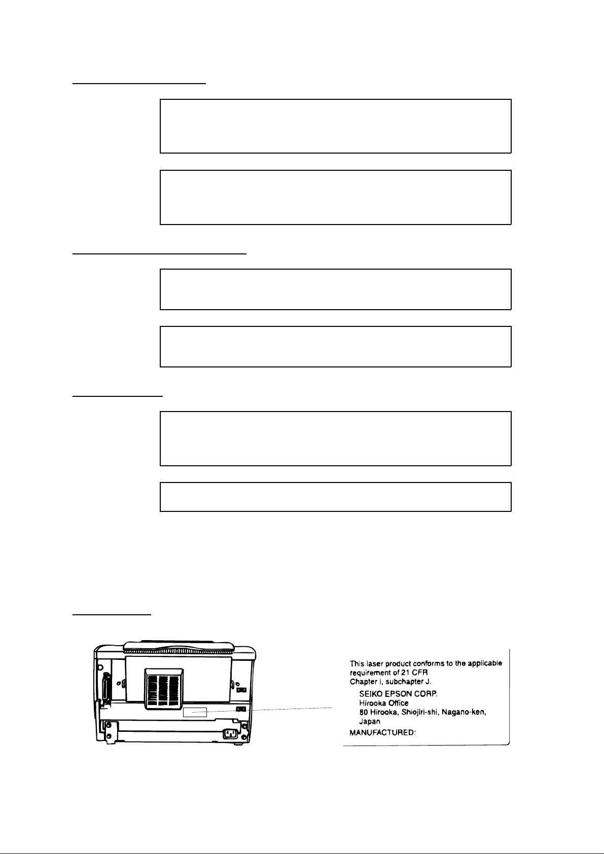
Laser Safety Labels
[Label on rear printer case]
A laser safety labels is attached on the outside of the printer shown below.
For United State
- iv -
Page 7
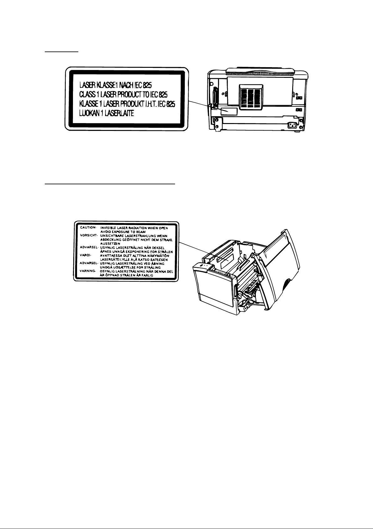
For Europe
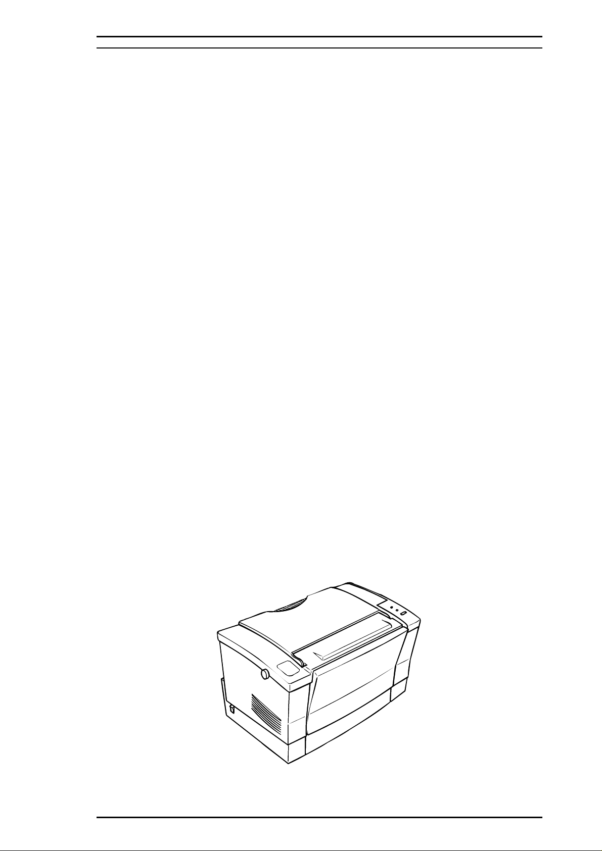
[Label inside printer]
The following laser safety label will be attached inside the printer as shown below.
For Denmark, Finl and, Sweden, and Norway
- v -
Page 8

PREFACE
This manual describes functions, theory of electrical and mechanical operations, maintenance, and repair
of EPL-5500.
The instruct ions and proc edur es included herein are intended f or the experi ence rep air technici an, and
attenti on should be given t o the prec autions on the preceding page. The chapters are o rganized as
follows:
CHAP TER 1. GENERAL DESC RIPTION
Provides a general product overview, lists specifications, and illustrates the main components of the printer.
CHAP TER 2. OPERATING PR INCIPLES
Describes the theory of printer operation.
CHAPTER 3. DISASSEMB LY AND ASSEMBLY
Includes a step-by-step guide for product disassembly and assembly.
CHAP TER 4. ADJUSTMENTS
Includes a step-by-step guide for adjustment.
CHAPTER 5. TROUBLESHOOTING
Provides Epson-approved techniques for adjustment.
CHAP TER 6. MAINT E NANCE
Describes preventive maintenance techniques and lists lubricants and adhesives required to service the equipment.
APPENDIX
Describes connector pin assignments, circuit diagrams, circuit board component layout and exploded diagram.
The contents of this manual are subject to change without notice.
- vi -
Page 9

REVISION SHEET
Revision Issue Date Revision Page
Rev. A October 06, 1995 1st issue
Revise the whole pages of the
following chapters:
Chapter 1
Rev. B March 15, 1996
Chapter 2
Chapter 3
Chapter 4
Chapter 5
Chapter 6
- vii -
Page 10

Chapter 1 General Description
Table of Contents
1.1 FEATURES 1-1
1.2 SPECIFICATIONS 1-3
1.2.1 Basic Specification . . . . . . . . . . . . . . . . . . . . . . . . . . . . . . . . . . . . . . . . . . . 1-3
1.2.2 Electrical Specifications . . . . . . . . . . . . . . . . . . . . . . . . . . . . . . . . . . . . . . . 1-5
1.2.3 Reliability Specifications. . . . . . . . . . . . . . . . . . . . . . . . . . . . . . . . . . . . . . . 1-5
1.2.4 Environmental Conditions for Operating (Include Imaging Cartridge) . . . . 1-5
1.2.5 Environmental Conditions for Storage and Transportation . . . . . . . . . . . . 1-5
1.2.6 Applicable Standards . . . . . . . . . . . . . . . . . . . . . . . . . . . . . . . . . . . . . . . . . 1-6
1.2.7 Specifications for Consumable. . . . . . . . . . . . . . . . . . . . . . . . . . . . . . . . . . 1-6
1.2.8 Physical Specifications. . . . . . . . . . . . . . . . . . . . . . . . . . . . . . . . . . . . . . . . 1-6
1.2.9 Software Specifications . . . . . . . . . . . . . . . . . . . . . . . . . . . . . . . . . . . . . . . 1-7
1.3 INTERFACE SPECIFICATIONS 1-9
1.3.1 Parallel Interface. . . . . . . . . . . . . . . . . . . . . . . . . . . . . . . . . . . . . . . . . . . . . 1-9
1.3.1.1 Compatibility Mode of Parallel Interface . . . . . . . . . . . . . . . . . . . . 1-9
1.3.1.2 Reverse ModeMode Signal Timing . . . . . . . . . . . . . . . . . . . . . . . 1-11
1.3.2 Serial Interface . . . . . . . . . . . . . . . . . . . . . . . . . . . . . . . . . . . . . . . . . . . . 1-15
1.3.3 Optional LocalTalk Interface. . . . . . . . . . . . . . . . . . . . . . . . . . . . . . . . . . . 1-17
1.4 OPERATING INSTRUCTIONS 1-18
1.4.1 Control Panel . . . . . . . . . . . . . . . . . . . . . . . . . . . . . . . . . . . . . . . . . . . . . . 1-18
1.4.2 Printer Settings Functions . . . . . . . . . . . . . . . . . . . . . . . . . . . . . . . . . . . . 1-20
1.4.3 Service Mode . . . . . . . . . . . . . . . . . . . . . . . . . . . . . . . . . . . . . . . . . . . . . . 1-23
1.4.3.1 Heaxadecimal Dump Mode. . . . . . . . . . . . . . . . . . . . . . . . . . . . . 1-23
1.4.3.2 EEPROM Initialize Mode. . . . . . . . . . . . . . . . . . . . . . . . . . . . . . . 1-23
1.4.3.3 Factory Reset Mode . . . . . . . . . . . . . . . . . . . . . . . . . . . . . . . . . . 1-23
1.4.3.4 Default Setting Mode. . . . . . . . . . . . . . . . . . . . . . . . . . . . . . . . . . 1-24
1.4.4 Display of Messages . . . . . . . . . . . . . . . . . . . . . . . . . . . . . . . . . . . . . . . . 1-27
1.4.4.1 Status Messages. . . . . . . . . . . . . . . . . . . . . . . . . . . . . . . . . . . . . 1-27
1.4.4.2 Error Messages . . . . . . . . . . . . . . . . . . . . . . . . . . . . . . . . . . . . . . 1-27
1.4.4.3 Service Call Error Message. . . . . . . . . . . . . . . . . . . . . . . . . . . . . 1-27
1.4.5 Printer Sharing . . . . . . . . . . . . . . . . . . . . . . . . . . . . . . . . . . . . . . . . . . . . . 1-28
1.4.5.1 Port Fixed Mode . . . . . . . . . . . . . . . . . . . . . . . . . . . . . . . . . . . . . 1-28
1.4.5.2 Auto Sense Mode . . . . . . . . . . . . . . . . . . . . . . . . . . . . . . . . . . . . 1-28
1.4.6 Emulation Mode Switch Function. . . . . . . . . . . . . . . . . . . . . . . . . . . . . . . 1-29
1.4.6.1 Emulation Switch by SPL. . . . . . . . . . . . . . . . . . . . . . . . . . . . . . . 1-29
1.4.6.2 Intelligent Emulation Switch. . . . . . . . . . . . . . . . . . . . . . . . . . . . . 1-29
1.4.7 Bi Resolution Improvement Technology . . . . . . . . . . . . . . . . . . . . . . . . . 1-30
1.4.8 Toner Save Mode. . . . . . . . . . . . . . . . . . . . . . . . . . . . . . . . . . . . . . . . . . . 1-31
1.4.9 Optional Memory . . . . . . . . . . . . . . . . . . . . . . . . . . . . . . . . . . . . . . . . . . . 1-31
1.5 MAIN COMPONENTS 1-32
1.5.1 C169 MAIN-B Board. . . . . . . . . . . . . . . . . . . . . . . . . . . . . . . . . . . . . . . . . 1-33
1.5.2 PWB-E Board. . . . . . . . . . . . . . . . . . . . . . . . . . . . . . . . . . . . . . . . . . . . . . 1-34
1.5.3 PWB-F Board . . . . . . . . . . . . . . . . . . . . . . . . . . . . . . . . . . . . . . . . . . . . . . 1-34
1.5.4 Optical Unit. . . . . . . . . . . . . . . . . . . . . . . . . . . . . . . . . . . . . . . . . . . . . . . . 1-35
1.5.5 FUSING UNIT. . . . . . . . . . . . . . . . . . . . . . . . . . . . . . . . . . . . . . . . . . . . . . 1-35
1.5.6 Photoconductor Unit. . . . . . . . . . . . . . . . . . . . . . . . . . . . . . . . . . . . . . . . . 1-36
Page 11

1.5.7 Developing Cartridge. . . . . . . . . . . . . . . . . . . . . . . . . . . . . . . . . . . . . . . . 1-36
1.5.8 Lower Paper Cassette Unit. . . . . . . . . . . . . . . . . . . . . . . . . . . . . . . . . . . 1-36
List of Figures
Figure 1-1. Exterior View of the EPL-5500 . . . . . . . . . . . . . . . . . . . . . . . . . . . . . 1-1
Figure 1-2. Printable Area. . . . . . . . . . . . . . . . . . . . . . . . . . . . . . . . . . . . . . . . . . 1-4
Figure 1-3. Compatibility Mode Signal Timing . . . . . . . . . . . . . . . . . . . . . . . . . . 1-9
Figure 1-4. Parallel Interface State Switch Diagram. . . . . . . . . . . . . . . . . . . . . 1-12
Figure 1-5. Negotiation Timing Chart . . . . . . . . . . . . . . . . . . . . . . . . . . . . . . . . 1-13
Figure 1-6. Timing Chart of Data Transfer . . . . . . . . . . . . . . . . . . . . . . . . . . . . 1-13
Figure 1-7. Termination Timing Chart. . . . . . . . . . . . . . . . . . . . . . . . . . . . . . . . 1-14
Figure 1-8. Timing Chart of Interrupt. . . . . . . . . . . . . . . . . . . . . . . . . . . . . . . . . 1-14
Figure 1-9. Control Panel . . . . . . . . . . . . . . . . . . . . . . . . . . . . . . . . . . . . . . . . . 1-18
Figure 1-10. Port Fixed Mode . . . . . . . . . . . . . . . . . . . . . . . . . . . . . . . . . . . . . . 1-28
Figure 1-11. Auto Sense Mode. . . . . . . . . . . . . . . . . . . . . . . . . . . . . . . . . . . . . 1-28
Figure 1-12. Emulation Switch by SPL . . . . . . . . . . . . . . . . . . . . . . . . . . . . . . . 1-29
Figure 1-13. Intelligent Emulation Switch . . . . . . . . . . . . . . . . . . . . . . . . . . . . . 1-29
Figure 1-14. Effect of RITech . . . . . . . . . . . . . . . . . . . . . . . . . . . . . . . . . . . . . . 1-30
Figure 1-15. RITech Adjustment. . . . . . . . . . . . . . . . . . . . . . . . . . . . . . . . . . . . 1-30
Figure 1-16. Toner Save Mode. . . . . . . . . . . . . . . . . . . . . . . . . . . . . . . . . . . . . 1-31
Figure 1-17. Component Layout . . . . . . . . . . . . . . . . . . . . . . . . . . . . . . . . . . . . 1-32
Figure 1-18. C169 MAIN - B Board. . . . . . . . . . . . . . . . . . . . . . . . . . . . . . . . . . . 1-33
Figure 1-19. PWB-E Board . . . . . . . . . . . . . . . . . . . . . . . . . . . . . . . . . . . . . . . . 1-34
Figure 1-20. PWB-F Board . . . . . . . . . . . . . . . . . . . . . . . . . . . . . . . . . . . . . . . . 1-34
Figure 1-21. Optical Unit . . . . . . . . . . . . . . . . . . . . . . . . . . . . . . . . . . . . . . . . . . 1-35
Figure 1-22. Fusing Unit . . . . . . . . . . . . . . . . . . . . . . . . . . . . . . . . . . . . . . . . . . 1-35
Figure 1-23. Photoco nduct or Uni t. . . . . . . . . . . . . . . . . . . . . . . . . . . . . . . . . . . 1-36
Figure 1-24. Developing Cartridge . . . . . . . . . . . . . . . . . . . . . . . . . . . . . . . . . . 1-36
List of Tables
Table 1-1. Options for the EPL-5500. . . . . . . . . . . . . . . . . . . . . . . . . . . . . . . . . . 1-2
Table 1-2. Paper Feed Methods . . . . . . . . . . . . . . . . . . . . . . . . . . . . . . . . . . . . . 1-3
Table 1-3. Paper Types. . . . . . . . . . . . . . . . . . . . . . . . . . . . . . . . . . . . . . . . . . . . 1-3
Table 1-4. Usability of Special Papers . . . . . . . . . . . . . . . . . . . . . . . . . . . . . . . . 1-4
Table 1-5. Electrical Specifications. . . . . . . . . . . . . . . . . . . . . . . . . . . . . . . . . . . 1-5
Table 1-6. Differences between EPSON GL/2 and GL/2 in the HP LaserJet 4
Emulation. . . . . . . . . . . . . . . . . . . . . . . . . . . . . . . . . . . . . . . . . . . . . . . . . . . . . . . 1-7
Table 1-7. Built-in Fonts . . . . . . . . . . . . . . . . . . . . . . . . . . . . . . . . . . . . . . . . . . . 1-7
Table 1-8. Parallel Interface Pin Assignment. . . . . . . . . . . . . . . . . . . . . . . . . . 1-10
Table 1-9. Parallel Interface Pin Assignment. . . . . . . . . . . . . . . . . . . . . . . . . . 1-11
Table 1-10. Serial Interface Connector Pin Assignments . . . . . . . . . . . . . . . . . 1-15
Table 1-11. LocalTalk Connector Pin Assignments . . . . . . . . . . . . . . . . . . . . . 1-17
Table 1-12. Printer Settings. . . . . . . . . . . . . . . . . . . . . . . . . . . . . . . . . . . . . . . . 1-20
Table 1-13. Service MOde Select Timing. . . . . . . . . . . . . . . . . . . . . . . . . . . . . 1-23
Table 1-14. Default Settings Codes . . . . . . . . . . . . . . . . . . . . . . . . . . . . . . . . . 1-24
Table 1-15. Error Messages . . . . . . . . . . . . . . . . . . . . . . . . . . . . . . . . . . . . . . . 1-27
Table 1-16. Differences in Components for the C169 MAIN-B Board . . . . . . . 1-33
Page 12

Rev. A 1-iii
Page 13
EPL-5500 Service Manual General Description
1.1 FEATURES
The EPSON EPL-5500 is non-impact page printer that combines a semi-conductor laser with
electrophotographic technology. This printer is small and light, and features high-speed,
high-resol ut ion print ing. Mai nte nance is ver y easy as a result of various built-in di agnos t ic functions.
The main features are:
❏
No ozone
Printing speed — 6 ppm (pages per minute)
❏
Resolution — 600/300 dpi (dots per inch)
❏
Light weight — about 5 kg (11 lb)
❏
Small footprint
❏
Low running cost: separation of the development/toner cartridge and photoconductor unit
❏
HP LaserJet 4 emulation mode
❏
22 built-in scalable fonts (8 Agfa and 14 TrueType fonts)
❏
High-performance controller (the controller’s CPU is a 22.5 MHz SPARKlite (MB86933H))
❏
Bi Resolution Improvement Technology (BiRITech) refines the print quality by eliminating
❏
jagged edges from images and characters on 600 dpi and 300 dpi printing
Memory Improvement Technology suppor ted
❏
Optional EPSONScrip t Level 2 (PostScript compatible) module
❏
Optional WPS (Windows Printing System) ROM SIMM module
❏
❏
Optional I239X, ESC/P 2 , and FX emulation ROM SIMM module
EPSON Micro Gray Technology (EMGTech), which is available when using PCL and
❏
EPSONScript Level 2 mode, refines gray scale printing to be comparable to printing on a
1200-dpi printer
❏
Small and low-cost optional LocalTalk with ser ial interface module
1MB standar d RAM and memory expansion availabl e up to 32MB of RAM with the addition of
❏
opt ional SIM M s
Bidirectional parallel interface
❏
Toner-saver mode supported
❏
A multi-user, multi-emulation mode
❏
IES (Intel li gent Emul ation Switch) allows switching between EP SONScript mode and another
❏
mode
SPL (Shared Printer Language) enabl es switching of the printer mode by command
❏
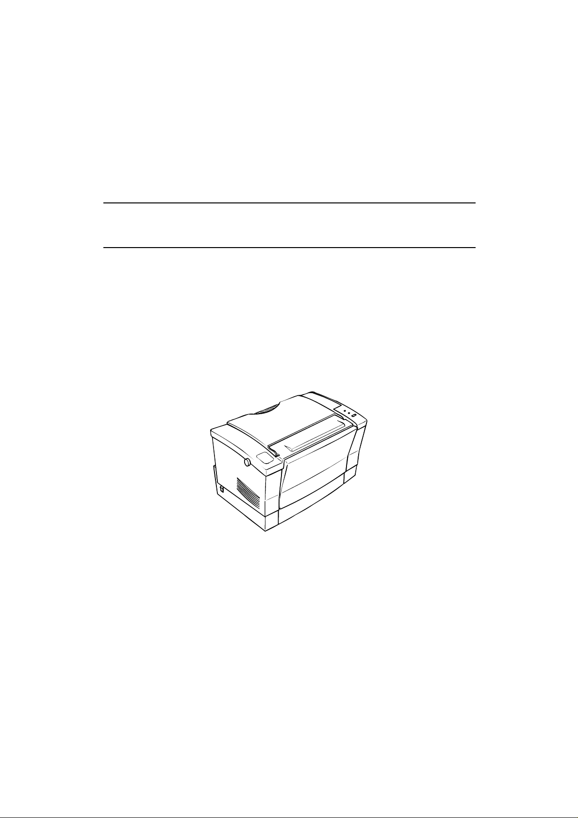
Figure 1-1 shows an exterior view of the EPL-5500.
Figure 1-1. Exter ior View of the EPL-5500
Rev. B 1-1
Page 14

General Descript ion E PL-5500 Ser vice Manual
Table 1-1 lists the optional units available for the EPL-5500.
Table 1-1. Optio ns for the EPL-5500
Cat. No. Description Note
C83218✽
C83219✽
C83220✽
—
—
C812491
S050005 Developer cartridge Develo per and toner cartridge
S051029 Photoconductor unit —
C82334✽ LocalTalk with serial I/F module (see Note 3)
C83614✽ Interface cable RS-232C extens ion cable for C82334✽
C82335✽ Type-B EX box Type-B I/F card box (see Note 4)
Windows Printing System ROM SIMM Supports Window s Printi ng System
EPSONScript Level 2 ROM SIMM Supports EPSONScript Level 2 mode
(PostScript Level 2 compatible) fonts and
commands (see Note 1)
LQ/FX/I239X ROM SIMM Supports ESC/P 2, FX, and IBM
2390/2391 emulation modes
NLSP Bitmap 2 font ROM Supports local NLSP bitmap fonts
(see Note 2)
NLSP Scalable font ROM Suppor ts local NLSP scalable fonts
(see Note 2)
250-sheet lower paper cassette for the
EPL-5500 (A4/B5)
Lower paper cassette
C82307✽/
C82308✽
C82310✽/
C82311✽
C82312✽ LocalTalk card ( see Not e 5)
C82313✽ GPIB card (see Note 5)
C82314✽ COAX interface card (see Note 5)
C82315✽ TWINAX interface card (see Note 5)
C82324✽ Ethernet interface card for NetWare
C82328✽ FAX card (see Note 5)
C82331✽ Multi protocol Ethernet card (see Note 5)
Notes:
1. Requires added memory (RAM) over a total of 2 MB, including standard RAM.
2. NLSP font ROMs do not support ESC/P 2 and FX modes.
3. LocalTalk with ser ial I/F module (C82334✽ ) cannot be used with Type-B EX box (C82335✽).
4. Type-B EX box (C82335✽) cannot be used with LocalTalk with serial I/F module (C82334✽) .
5. Type-B EX box (C82335✽) must be installed while usin g the Type-B I/F card.
32 KB serial interface card (see Note 5)
32 KB parallel interface card (see Note 5)
(see Note 5)
1-2 Rev. B
Page 15

EPL-5500 Service Manual General Description
1.2 SP ECIFICAT IONS
This section provi des statisti cal data for the EPL-5500.
1.2.1 Basic Specifications
Printing method: Laser beam scanning and dry electrophotogra phy
Resolu tion: 600/300 dpi
Printing speed: 6 ppm (letter/A4)
First printing ti me (A4/LT): Less than 20 seconds (face-up output)
Warm-up time: Less than 35 seconds
(at rated current and 23° C (73° F) temperature)
Paper supply: See Table 1-2.
Table 1-2. Paper Feed Methods
Capacity Using
Paper Supply
Standard built-in paper tray 150 A5, B5, A4, LT,
Manual feed slot 1 Any size feedable
Lower paper cassette (optional) 250 A4, B5 16 to 24 lb.
Notes:
1.
The weight in pounds (lb) is determined by the weight of 500 sheets cut to 17 × 22 inches;
1 g/m2 = 0.2659763 lb.
2. Paper size range: width 3 to 8.5 inches (76 to 216 mm)
length 5 to 14.0 inches (127 to 356 mm)
20 lb. (75 g/m2)
Paper
5 to 10 Monarch,
Pap er Si z e
GLT, EXE, LGL,
GLG, F4, HL
DL, C5, C6,
International B5,
Commercial-10
(Note 2)
Usage Thick ness
(Ream Weight)
16 to 24 lb.
(60 to 90 g/m2)
Envelopes made
of 20 to 24 lb.
(75 to 90 g/m2)
paper
16 to 42 lb.
(60 to 157 g/m2)
(60 to 90 g/m2)
Paper types: See Table 1-3.
Table 1-3. Paper Types
Rev. B 1-3
Page 16
General Descript ion E PL-5500 Ser vice Manual
Standard paper Xerox 4024 DP paper
20 lb (75 g/m2)
Normal paper Regular photocopier paper
Bond paper
Recycled paper
16 to 24 lb (60 to 90 g/m2)
Special papers Card stock (90 to 157 g/m2)
Envelopes
Labels
Letterhead
Transparency (OHP) sheets
Colored paper
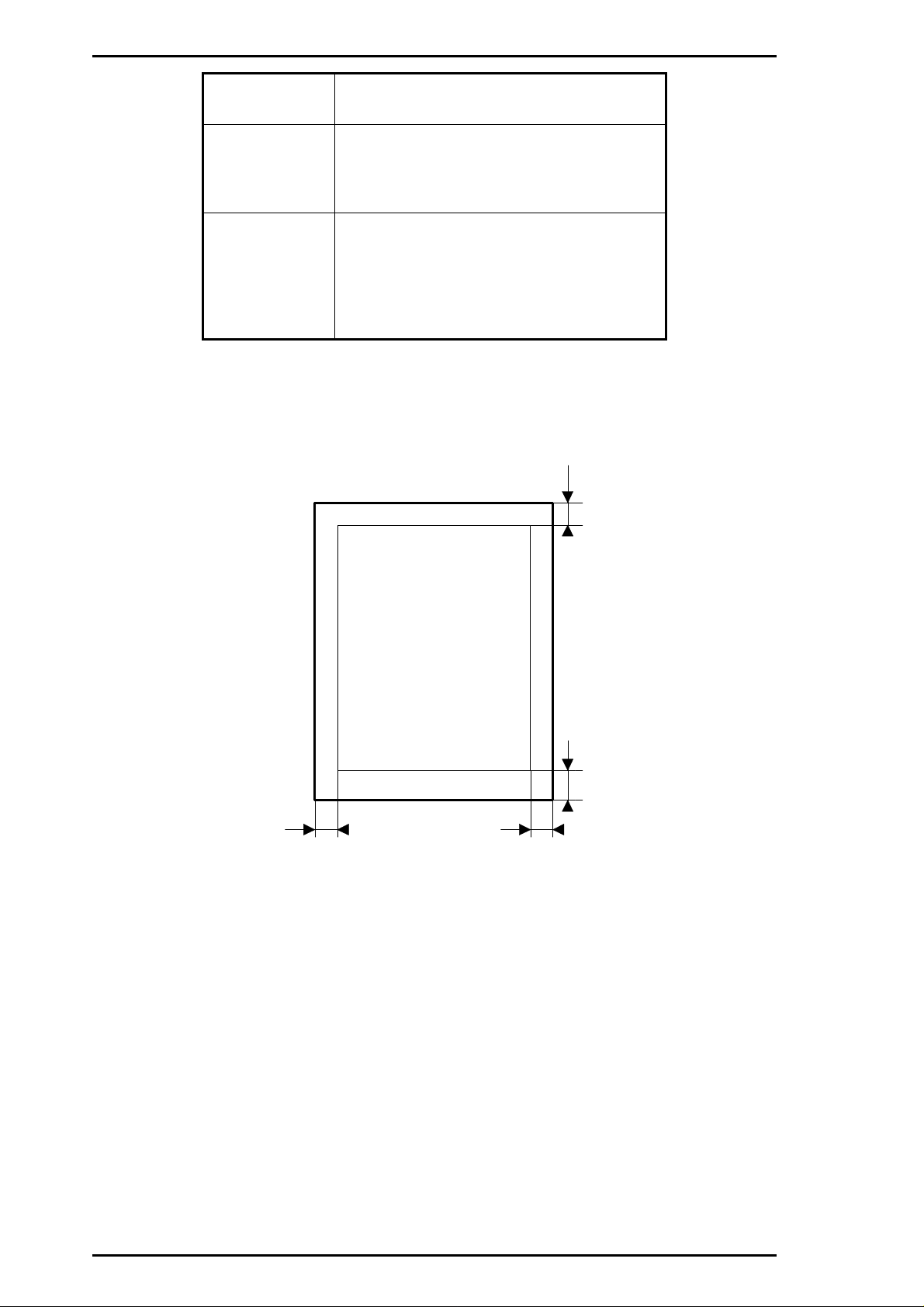
4.0 mm
Printable Area
4.0 mm4.0 mm
Figure 1-2. Printable Area
4.0 mm
1-4 Rev. B
Page 17

EPL-5500 Service Manual General Description
Usability of special papers: See Table 1-4.
Tab le 1- 4. Usabi li t y of S pecial Pa pers
Input OHP Envelopes Labels Card Stock Letterhead
Standard built-in
paper tray
Manual feed slot P P P P R
Lower paper cassette N N N N P
R: Reliable feeding and good image quality.
P: Possible, but better avoided.
N: Not supported.
Paper feed alignment and direction: Center alignment for all sizes
Paper ejection: Face down
Output tray capacity: 100 sheets (face down)
Printa ble area (standard paper): See Figure 1-2.
Note:
Noise: Less than 35 dB(A), standby
Ozone density: Less than 0.01 ppm
Toxici ty: No toxicity e xists i n organi c photoconduct or (OP C), toner,
The actual printable area depends on the printer mode.
PPPPR
Less than 47 dB(A), operating
or plastic material s
Rev. B 1-5
Page 18

General Descript ion E PL-5500 Ser vice Manual
1.2.2 Electrical Specifications
Table 1-5. Electrical Requirements and Ranges
Description 100 V Version 200 V Version
Rated voltage 100 ∼ 120 VAC 220 ∼ 240 VAC
Input voltage range
Rated frequency range
Input frequency range
Power consumption Less than 500 W Less than 600 W
Power consum ption while in
standby mode
90 ∼ 132 VAC 198 ∼ 264 VAC
50 ∼ 60 Hz
47 ∼ 63 Hz
Less than 15 W
(witho ut option)
1.2.3 Reliability Specifications
MPBF (Mean Prints Between Failures ): Over 25,000 sheets
Note:
MTBF (Mean Time Between Failures): 3000 power on hours (POH)
Jam rate: 1 out of 2,000 sheets or le s s (excluding multip le-s heet feeding)
Feed failure: 1 out of 2,000 sheets or le ss (excludi ng multip le-sheet fe eding)
Multiple paper feeds: 1 out of 500 sheets or less
Paper curl height: 30 mm (1.2 inches) or less
Leading edge bending (1 cm or more): 1 out of 1,000 sheets
MTTR (Mean Time To Repair): 30 minutes or less
Durability: 5 years or 180,000 sheets
MPBF indicates average number of pages printed bef ore occ urrence of pr oblem requiring
replacement or service.
1.2.4 Environmental Conditions for Operation (Including Imaging Cartridge)
Temperature:
Humidity: 15 to 85% RH
Altitude: 2,500 m (8,200 feet) or lower
Levelness:
Illuminance: 3,000 lux or less (Must not be exposed to direct sunl ight.)
Surrounding space: Printer should have at least 100 mm of clearance on its
10 to 35° C (50 to 95° F)
1°
sides and rear.
1.2.5 Environmental Conditions for Storage and Transportation
Temperature:
Humidity: 30 to 85% RH
Drop test: Clear to JIS Z0200-1987 Level 1
Vibration: Vibration frequency 5 to 100 Hz and 100 to 5 Hz
Resistance to atmospheric pressure: More than 61.3 KPa
Storage life: 18 m onths (followi ng date of manufactur e)
0 to 35° C (32 to 95° F)
Acceleration 1 G
Acceleration direction 3 direction
1-6 Rev. B
Page 19

EPL-5500 Service Manual General Description
1.2.6 Ap p licab le St andards
Safety Sta ndards
120 VAC model: UL 1950, CSA 22.2 No. 950 Deviation 3
220/240 VAC model: EN 60950 (IEC950), NEMKO (IEC950), SETI (IEC950),
SEMKO (IEC950), DEMKO (IEC950)
Safety Regulations (Laser Radiation)
12 0 VAC model: FDA (NCDRH) Class 1
220/240 VAC model: VDE 0837 (Laser Class 1) (IEC825), SETI (IEC 825) , SEMKO
(IEC825), DEMKO (IEC825)
EMI
120 VAC model: FCC Part 15 Subpart B Class B, DOC Class B
220/240 VAC model: Vfg 243 (VDE 0878 Part 3,3 0)
EN55022 Class B (CISPR Pub.22 Class B)
CE marking, EMC
Others
Toner: No effect on human health (OSHA-TSCA, EINE CS)
OPC: No effect on human health (OSHA)
Ozone: Less than 0.01 mmp
other UL478 (5th edition)
Materials: SWISS environmental law (must contain no CdS)
1.2.7 Specifications for Consumables
Life: Develo per and toner cartridge: 3,000 pages
Photo conductor unit : 20,000 pages
Note:
In continuous printi ng mode wit h A4/letter p aper at a 5% image ratio (black/whi te ratio).
The life varies, depending on the printing mode (continuous or intermittent) and/or the
image ratio.
Environmental Conditions for Storage and Transportation
Temperat ure:
Humidity: 30 to 85% RH
Drop test: Height 76 cm (30.4 inches)
Vibration: Same as printer
Resistance to atmospher ic pres sure: More than 74 Kpa
Storage term: 18 months (following date of manufacture)
0 to 3 5° C (32 to 95° F)
1.2.8 Physical Specifications
Dimensions (Width × Depth × Height):
Printe r: 352 × 264 × 299 mm (13.9 × 10.4 × 11.8 inches)
Weight: Approx. 5 kg (11 lb), with consumables, excluding all options
Rev. B 1-7
Page 20

EPL-5500 Service Manual General Description
1.2.9 Software Specifications
Built-in modes: HP LaserJet 4 emulation (P CL 5e)
EPSON GL/2 mode (GL-like mode)
Note:
EPSON GL/2 mode is similar to the GL/2 mode included in the HP LaserJet 4 emulation.
Table 1-6 shows the differences between EPSON GL/2 mode and the LJ4 GL/2 mode.
While in EPSON GL/2 mode, the operator can enter GL/2 mode without sending the
ESC %#B (Enter GL/2 mode) command. If the operator’s application software cannot
send the ESC %#B command, then use this mode.
Table 1-6. Differences between EPSON GL/2 and
GL/2 in the HP LaserJet 4 Emulation
EPSON GL/2 Mode
PCL mode Not available Initial mode
Paper eject Supports PG, AF commands Supported in PCL
Auto eject SelecType setting Not available
Reduced printing SelecType setting Available in PCL
Switch to PCL
(ESC %#A)
Reset (ES C E) Ejects paper and then initializes Ejects paper, switches to PCL,
PJL, EJL, and ES Supp orted Supported
Advance full page
(PG, AF)
Note:
Optional modes : EPSONSc r ip t Level 2 (PostScript Level 2 emulation) mode
Auxiliary software: Hex dump
Built-in fonts: See Table 1-7.
The EPL-5500 GL/2 mode features all the commands of the LJ4-GL/2 mode, plus a few
additional commands. The GL/2 mode emulates some of the HP-GL
etc.) commands. If the application software uses unsupported commands for the GL/2
mode, print cannot be assured.
FX (FX-870/ 1170, LX-100) emulation mod e
ESC/P 2 (Stylus 800/1000) emulation mode
WPS (Windows Printing System) mode
Status sheet
Font sample
Not supported Supported
Supported Not supported
GL/2 for HP LaserJet 4
Emulati on Mode
and then initializes
plotter (HP 7475A,
Table 1-7. Built-in Fonts
Resident Fon ts
Bitmap fonts
Line Printer16.66 cpi(Po rtrait)
Scalable fonts
Dutch
Dutch 801Bold SW C
Dutch 801Italic SW C
Dutch 801Bold Italic SWC
Swiss
Swiss 742Bold SWC
Swiss 742Medium Italic SW C
S: Supported, NS: Not Supported
801Roman SWC
742SWC
Applicable Mode
HP LJ4, GL/2
S
S
S
S
S
S
S
S
Rev. B 1-7
Page 21

General Description EPL-5500 Service Manual
Table 1-7. Built-in Fonts (Continued)
Applicable Mode
Resident Fon ts
Scalable fonts
Swiss 742Bold Italic SWC
Swiss 721Rom an SWM
Swiss 721Bold SWM
Swiss 721Oblique SWM
Swiss 721Bold Oblique SWM
Dutch 801Roman SWM
Dutch 801Bold SW M
Dutch 801Italic SW M
Dutch 801Bold Italic SWM
Symbol SetSWA
More WingBatsSWM
CourierSWC
CourierBold SW C
CourierItalic SWC
CourierBold Italic SWC
S: Supported, NS: Not Supported
HP LJ4
GL/2
S
S
S
S
S
S
S
S
S
S
S
S
S
S
S
1-8 Rev. B
Page 22

EPL-5500 Service Manual General Description
1.3 INTERFACE SPECIFICATIONS
The EPL-5500 is eq uip ped with the following externa l inter fac es :
❏ Par allel inte rfac e
❏ Optio n al Loca lTalk/serial interface
❏ Optio n al Type B interface with Type-B EX box
1.3.1 Parallel Interface
The parallel interface has the following two modes:
❏ Com patibility mod e (s ame as par allel in te rfac e for EPS ON’ s cu rre n t page prin te r)
❏ Rev er se mo de
1.3.1.1 Parallel Interface Compatibility Mode
System: STROBE synchronization, 8-bit par allel data tran sf er
Handshakin g: BUSY and
Connector type: P90-25027-1 (Amphenol) recept acle
Applicable plug: 57-30360 (A mph enol or equivalent)
Transfer spe e d : Approximat ely 400, 000 bytes/second (ma x.)
Signal timing: S ee F ig ur e 1-3.
Signal descript ion : See Table 1-8.
ACKNLG signals
DATA 1-8
STROBE
0.5
BUSY
ACKN LG
0.5 µ s
(minimum)
0.5 µ
s
(minimum)
VALID VALID
0.5
s (minimum)
µ
s (maximum)
µ
0 s
0.5 or 5 µ
s
(min.)
(minimum)
1 or 10
s
µ
(typical)
Figure 1-3. Compatibility Mode Signal Timing
Rev. B 1-9
Page 23

General Description EPL-5500 Service Manual
Table 1-8. Parallel Interface Pin Assignments
Pin No. Signal Name I/O Description
STROBE
1
STROBE is a strobe pulse used to read data from the host
computer. The pulse width must be more than 0.5 µsec.
IN
Normally it is HIGH, and data is latched at the trailing edge of
this signal.
2-9
10
11
12
13
14
15
16
DATA 1-8
ACKNLG
BUSY
PE
SLCT
AUTO-FEED
NC
GND
DATA 1 to 8 are parallel data bits. Whe n the sig nal is HIGH, the
data bit is 1, and when it is LOW, the data bit is 0. The most
IN
significant bit (MSB) is DATA 8. The signal state must be
maintained for 0.5 µsec. on either side of the
active edge.
ACKNLG is an acknowledge pulse with an approximate width
of 1 or 10 µsec. This signal goes LOW when the data reception is
OUT
completed, which indic ates tha t the printer c an ac ce pt new data.
Timing with the BUSY signal is specified through SelecType.
The BUSY signal informs the host computer of the printer state.
OUT
When the signal i s HIGH, the pr i nter cann ot accept d a ta.
The PE signal indicates paper empty for the standard tray
OUT
selected through SelecType or command, or for the optional
paper cassette. Paper empty is indicated by HIGH.
OUT
Used in reverse mode.
IN
Not used.
—
Not used.
—
Logic ground level.
STROBE signal
17
18
19-30
31
32
33
34
35
36
CHASSIS GND
NC
GND
INIT
ERROR
GND
NC
+5
SLCT IN
Connected to the pr inter chassis . The print er chassis GND and
—
the signal GND ar e c onn ec ted to each other.
—
Not connected.
—
Ground level for the twiste d pair r eturn signal.
IN
The
STROBE signal is ignored when this signal is LOW.
This level goes LOW whe n the pr inter is:
• Out of paper
OUT
• Paper jam
• In the error state
• Off line
—
Same as for pi n s 19 t o 30.
—
Not used.
—
Pulled up to +5 V throu gh 1. 0K -ohm resistance.
—
Used in reverse mode.
1-10 Rev. B
Page 24

EPL-5500 Service Manual General Description
1.3.1.2 Reverse Mode
Reverse mode for the EPL-5500 supports the IEEE-P1284 nibble mode. This printer can run in
reverse mode, in which the printer can inform the computer of its status with EJL and PJL
commands.
System: IEEE-P1284 nibble mode
Connector type: P90-25027-1 (Amphenol) recept acle
Applicable plug: 57-30360 (A mph enol or equivalent)
Signal descript ion : See Table 1-9.
Table 1-9. Parallel Interface Pin Assignment
Pin No. Signal Name I/O Description
1
STROBE
HostClk: This signal is a strobe pulse used to read extension
IN
request values from the host computer durin g n egot iat ion.
DATA 1-8
2-9
10
ACKNLG
BUSY
11
PE
12
SLCT
13
AUTO-FEED
14
15
NC
16
GND
CHASSIS GND
17
These signals are data bits of extension request values received
during negotiation. Th is printer suppo rts fo llowing v alues :
IN
0000 0100: Requ es t Device ID (sent in nibble mode)
0000 0000: Requ es t nibble mod e
OUT
PtrClk: Printer sends clock data.
PtrBusy: P rinter s ends da ta bits 3 and 7 during d ata tr ansfer to
OUT
host computer.
AckDataReq: Printer sends data bits 2 and 6 during data
OUT
transfer to host computer.
Xflag: Printer sends data bits 2 and 6 during data transfer to
OUT
host computer.
HostBusy: This signal informs the printer of the host computer’s
IN
state. When the signal is HIGH, the host computer cannot
accept data.
—
Not used.
—
Logic ground level.
Connected to the pr inter chassis . The print er chassis GND and
—
the signal GND ar e c onn ec ted to each other.
18
19-30
31
32
33
34
35
36
NC
GND
INIT
ERROR
GND
NC
+5
SLCT IN
—
Not connected.
—
Ground level for the twiste d pair r eturn signal.
IN
nInit: Fixed at HIGH level.
nDataAvail: Printer sending data bits 0 and 4 during data
OUT
transfer to host computer.
—
Same as for pi n s 19 t o 30.
—
Not used.
—
Pulled up to +5 V throu gh 1. 0K -ohm resistance.
1284Active: If this signal is set to HIGH, this printer is actively
IN
in P1284 (rev er se mode).
Rev. B 1-11
Page 25

General Description EPL-5500 Service Manual
Compatibility Mode
Forward
Data
Transfer
ERR=HIGH
No da ta se nt
Host Busy
Data Not
Available
AUTO
FEED=LOW
STROBE
ACK and BUSY
SLCT IN=HIGH
ERR=HIGH
No da ta se nt
Forward
Idle
Negotiation
Reverse
Data
Transfer
Failed
Negotiat ion
Sending data
ERR=LOW
Sending data
AUTO
FEED=LOW
Request to
send data
Terminate
SLCT IN=LOW
ERR=L OW
Host Busy
Data
Available
AUTO
FEED=HIGH
Reverse
Idle
ERR=LOW
Figure 1-4. Parallel Interface State Switch Diagram
Figure 1-4 shows the switch diagram for the parallel in te rf ac e st ate.
Interrupt
Host
1-12 Rev. B
Page 26

DATA
SEL-IN
STROBE
AUTO-FEED
ACKNLG
Peripheral Busy StatusBUSY
PE
SLCT
ERROR
HB DA Negotiation
HB DA or
HB DNA
(Note 3)
Idle or
Transfer
Bit 3 Bit 7
Bit 2 Bit 6
Bit 1 Bit 5
Bit 0 Bit 4
Peripheral Busy Status
Note 1
Note 1
Note 2
EPL-5500 Service Manual General Description
Figure 1-5 shows the negotiation timi ng char t .
DATA 00h or 04h
SEL-IN
STROBE
AUTO-FEED
ACKNLG
Peripheral Busy StatusBUSY
Current Peripheral StatusPE Note1
Note 2SLCT
Current Peripheral StatusERROR Note1
Compatibility Negotiation HB DA or
Figure 1-5. Negotiation Timing Chart
Notes:
1. This signal is set to HIGH when no data is being sent .
This signal is set to LOW during sending of data.
2. This signal is set to HIGH if the extension request value was 04h.
3. HB DA: Host Busy Data is Available
HB DNA: Host Busy Data is Not Available
Figure 1-6 shows the data transfer timing chart.
Notes:
HB DNA
(Note 3)
Idle or
Transfer
1. This signal is set to HIGH when no data is being sent .
This signal is set to LOW during sending of data.
2. This signal is set to HIGH, if extension request value was 04h.
3. HB DA: Host Busy Data is Available
HB DNA: Host Busy Data is Not Available
Rev. B 1-13
Figure 1-6. Timing Chart for Data Transfer
Page 27

General Description EPL-5500 Service Manual
Figure 1-7 shows the t i ming chart for termination.
DATA
SEL-IN
STROBE
AUTO-FEED
ACKNLG
PE
SLCT
ERROR
Note 3
Peripheral Busy StatusBUSY
Note 1
Note 2
HB DNA, Idle,
or HB DA
Termination Compatibility
Figure 1-7. Termina tion Timing Chart
Notes:
1. The signal is HIGH when HB DNA.
The signal is LOW when HB DA.
2. The signal is set to HIGH, if the extension reques t value was 04h .
3. Idle = LOW.
Figure 1-8 shows the t i ming cha rt for in terr u pts .
Peripheral Busy Status
Current Peripheral Status
Current Peripheral StatusNote 1
DATA
SEL-IN
STROBE
AUTO-FEED
ACKNLG
PE
SLCT
ERROR
Note:
Peripheral Busy StatusBUSY
Note 1
Reverse Idle Interrupt
Figure 1-8. Timing Chart for Interrupts
The signal is set to HIGH, if the extension re que st value was 04 h.
HB DA Transfer
1-14 Rev. B
Page 28

EPL-5500 Service Manual General Description
1.3.2 Serial Interfac e
This printer can use the optional LocalTalk/serial interface module.
Type: RS-232C/current loop
Transfer system: Full duplex
Synchronization: Asynchronous start-stop system
Start-bit: 1 bit
Stop-bit: 1 or 2 bits
Data length: 7 bits or 8 bits
Parity: Odd, even, or none
Protocol: X-ON/X-OFF (can be c ombined wit h D TR con t ro l)
DTR control (can be c ombin ed with X-ON/X-OFF)
Transfer speed: 300, 600, 1200, 2400, 4800, 9600, 19200, 38400, or 57600 bps
Error: Overrun error: Processed as missing data and replaced by “*”
Pari ty error: Repla ced by “*”
Framing error: Replaced by “*”
Breaking c h ar ac te r: Ignored
Signal descript ion : See Table 1-10.
Table 1-10. Serial Interface Pin Assignments
Pin No. Signal Name I/O Description
CHASSIS-GND
1
Connected to the pr inter chassis . The print er chassis GND and
—
signal GND are connected to each other.
TXD
2
RXD
3
5
CTS
7
SIGNAL-GND
TTY-TXD
17
DTR
20
Serial ASCII data output by the printer. It maintains the
“MARK” state (LOW level) between transmitted character
OUT
codes. Logic 0 is at HIGH level (SPACE) and logic 1 is at LOW
level (MARK).
Serial ASCII data input to the printer. It maintains “MARK”
IN
state (LOW leve l) betw een r ec eiv ed character codes.
IN
Always ignored.
—
Ground.
Current loop signal: HIGH impedance (SPACE) between pins
17 and 24 or X-ON signal sent across pins 17 and 24 indicates
OUT
that the printer is ready to accept data; LOW impedance
(MARK) or X-OFF signal being sent indicates that the printer is
busy.
Signal output by printer. When the DTR signal is HIGH, the
printer can receive the RXD signal. The SelecType settings do
not specify DTR control, the signal level is HIGH while printer
OUT
power is on. When the SelecType setting is used for DTR
control, DTR goes LOW in case of any error conditions. The
data (RXD) from host computer must be stopped within 128
characte r s after DTR goes LOW.
23
TTY-RXD Retu rn
24
TTY-TXD Retur n
25
TTY-RXD
Note :
Rev. B 1-15
The DTR state can be selected through printer settings.
—
Current loop signal: Current return for pin 17
—
Current loop sign a l : Inp u t data current loop
IN
Current loop signal: Current return for pin 25
Page 29

General Description EPL-5500 Service Manual
Handshaking
When the vacant area for data in the input buffer drops to 256 bytes, the printer outputs an X-OFF
code or sets the DTR signal level to LOW, indicating that the printer cannot receive more data.
Once the vacant area for data in the buffer recovers to 512 bytes, the printer outputs an X-ON code
or sets the DTR flag to HIGH, indicating that the printer is again ready to receive data.
Protocol
There are two types of protocols, as listed below, and each of them can be designated by SelecType
independentl y.
❏
DTR/DSR protocol
SelecType is used to execute the DTR/DSR control protocol. The DTR signal is set to HIGH when
the printer is ready to receive data, and to LOW when conditions indicate an error or that the
receiving buffer is full.
When the error is cleare d a nd the print e r ret urns to on-line mode, the signal returns to HIG H. When
SelecType is used to set the DTR control OFF, DTR is always set to HIGH. The printer transmits
TXD only when DSR is at the HIGH level (DSR is always considered HIGH when the SelecType
setting for DSR is OFF). X-ON/X-OFF tran sm issi on is indepen d en t of the DSR state.
❏ X-ON/X-OFF (DC1/DC3) protocol
SelecType is used to execute the X-ON/X-OFF protocol. The X-OFF (DC3) code is output if status
indicates an error, and the printer warns the host to stop data transmission within 256 characters.
No further X-OFF codes are sent in response to additional data received from the host after the
X-OFF code has been sent once. The X-ON (DC1) code is output after all conditions given in the
error are cleared .
When the remaining capacity of the receive buffer reaches 512 characters, X-OFF (DC3) is output
once. It is sent only once, even if there are multiple errors. The printer goes on line automatically at
power on, and outputs an X-ON code. Transmission of X-ON/X-OFF codes can be defined by
SelecType.
1-16 Rev. B
Page 30

EPL-5500 Service Manual General Description
1.3.3 Optional LocalTalk Interface
This printer can use the optional LocalTalk/ serial int er fac e mod ule.
Type: LocalTalk
Signal level: Same as RS-422 sign al level
Protocol: X-ON/X-OFF (can not be co mbin ed wit h DTR c on trol)
DTR control (cann ot be combined with X-ON/X-OFF)
Transfer speed: 230.4K bps
Signal descript ion : See Table 1-11.
Table 1-11. LocalTalk Interface Pin Assignments
Pin No. Signal Name I/O Description
DTR
1
Signal output by the printer. When the DTR signal is HIGH, the
OUT
printer can receive the RXD signal.
2
CTS
TXD-
3
4
GND
RXD-
5
6
TXD+
7
NC
8
RXD+
IN
The printer transmit s the data through T XD while CTS is HIGH.
Serial ASCII d a ta output f rom the pri n ter.
HIGH level; whe n SD+ voltag e is high er than t h e SD - voltage.
OUT
LOW level; when SD+ voltage is les s th an the SD - voltage.
Logic 0 is SPACE and logic 1 is MARK. The state must be
main tained be tween transmitted character codes.
—
Ground.
Serial ASCII data input fr om c ompu t er .
HIGH level; when RD+ voltage is high er than RD - voltage.
IN
LOW level; when RD+ voltage is les s th an RD - vo ltage .
Logic 0 is “SPACE” and logic 1 is “MARK” state must be
main tained be tween transmitted character codes.
OUT
Refer to TXD-.
—
No connect.
IN
Refer to RXD-.
Rev. B 1-17
Page 31

General Description EPL-5500 Service Manual
1.4 OPERATING INSTRUCTIONS
This section describes functions performed through the control panel, such as printing a status
sheet, hexadecimal dump, and printer settings functions.
1.4.1 Control Pane l
The printer control panel gives you easy control over most common printer operations. The panel
consists of indicator lights and a button.
LED (Yellow)
LED (Red)
Button
Figure 1-9. Control Panel
Indicator lights
❏
Yellow light
ON: Communication with the host is possible.
Fast flashing: Receiving data or warming up.
Slow flashing: Received data is stored in the printer but has not been printed.
OFF: Printer is power off.
❏
Red light
ON: Paper jam or cov er open .
Fast flashing: Feed jam, paper empty.
Slow flashing: One of these errors: SOFT ERROR, PRINT OVERRUN, MEMORY OVERFLOW,
CHECK PAPE R SIZE , IMA GE OP TIMUM
OFF: No error condition.
1-18 Rev. B
Page 32

EPL-5500 Service Manual General Description
Functions of Pressing the Button
❏
While the Red light flashe s slowly:
Function of button Clears an error.
Operation Hold down the button until the yellow and Red lights both go on
after release. The prin ter prin ts a status sheet in dicatin g the er r or
type.
❏
While the Red light flashes fast:
Function of button Prints any of the following page.
- Feed jam or paper empty page
- Manual feed page
Operation Load the pape r or c lear the jam, and then hold down the button
until the yellow and Red lights go on, then release to continue
printing.
❏
While yellow light is flashing slow ly (ex cep t in EPSONS cript mod e):
Function of button Prints out data in the printer’s memory.
Operation Hold down the button until the yellow and red lights go on, then
release the button to continue printing.
❏
While the yellow light is on (except in W PS mod e):
Function of button Prints a status sheet.
Operation Hold down the button until the yellow and red lights go on, then
release the button to continue printing. The yellow light flash while
the status sheet is being printed.
❏
Reset (always effective ex ce pt du ring w ar m up or status sheet print ing ):
Function of button Clears current port.
Operation Hold down the button until the yellow and red lights go on, and
when these lights start flas h in g altern at ely, release the button.
❏
Warm boot (always effective except during warm up or status sheet printing):
Function of button Warm boot (same as power on reset, except for engine initialization).
Operation Hold down the button until the yellow an d red ligh ts start flas h in g
at the same time, then release the button.
Rev. B 1-19
Page 33

General Description EPL-5500 Service Manual
1.4.2 Printer Settings Functions
The printer settings function from the Remote Control Panel (software) lets the user control most of
the printer’s functions, such as printing test pages, selecting a paper size, and changing the printer’s
configuration. Table 1-12 shows the prin ter se ttin gs options.
Table 1-12. Printer Settings
Menu It em Avai lab le Options
PRINTING COPIES 1 to 999
PAGE SIZE A4, A5, B5, LT, H LT, LGL, G LT, GLG, EXE ,
F4, MON, C10, DL, C5, IB5, CTM
ORIENTATION PORT, LAND
MANUAL FEED OFF, ON
RITech OFF, LIGHT, MEDIUM, DARK
TONER SAVE OFF, ON
LJ4 FONT SRC RESIDENT, SIMM, DOWN LO AD
FONT NUMBER 0 to (available)
PITCH 0.44 to 99.99 CPI (0.01 steps)
HEIGHT 4.00 to 999.75 PT. (0.25 steps)
SYMSET Roman-8, ECM94-1, 8859-2 ISO, 8859-2 ISO,
IBM-US, IBM-DN, PcMultiling, PcE.Europe,
PcTk437, WiAnsi, WiE.Europe, WiTurkish,
DeskTop, PsText, VeInternati, VeUS,
MsPublishin, Math-8, PsMath, VeMath,
PiFont, Legal, UK, ANSI ASCII, Swedis2,
Italian, Spanish, German, Norweg1,
French2, Windows
FORM 5 to 128 lines
SRC SYMSET* 0 to 3199
DEST SYMSET* 0 to 3199
PS* ERR SHEET OFF, ON
MicroGray OFF, ON
PROTECT LEV EL 1 to 5
ESCP2* Font Courier, Roman, Sans serif, Roman-T,
Sans-H, Script
Pitch 10 CPI, 12 CPI, 15 CPI, Prop
Condensed OFF, ON
T-Margin 0.40 to 1.50 Inch (0.05 steps)
Text 1 to (available) lines
CG Table Pc USA, Italic, PcMultilin, PcPortuguese,
PcCanFrenc, PcNordic, PcTurk2,
Pc.E.Europe, BpBRASCII, BpAbicomp
Country USA, France, Germany, UK, Denmak,
Sweden, Italy, Spain1, Japan, Norway,
Denmark2, Spain2, LatinAmeric, Korea,
Legal
* With option
Table 1-12. Printer Settings (Co ntinued)
Menu It em Avai lab le Options
1-20 Rev. B
Page 34

EPL-5500 Service Manual General Description
ESCP2 * (Con tinued) Auto CR ON, OFF
Auto LF OFF, ON
Bit Image Dark, Light, BarCode
Zero Char
FX* Font Courier, Prestige, Roman, Sans serif, Script
Pitch 10 CPI, 12 CPI, 15 CPI, Prop
Condensed OFF, ON
T-Margin 0.40 to 1.50 Inch (0.05 steps)
Text 1 to (available) lines
CG Table Pc USA, Italic, PcMultilin, PcPortuguese,
Country USA, France, Germany, UK, Denmak,
Auto CR ON, OFF
Auto LF OFF, ON
Bit Image Dark, Light, BarCode
Zero Char
I239X* Font Courier, Prestige, Gothic, Orator Script,
φ
0,
PcCanFrenc, PcNordic, PcTurk2,
Pc.E.Europe, BpBRASCII, BpAbicomp
Sweden, Italy, Spain1, Japan, Norway,
Denmark2, Spain2, LatinAmerica
φ
0,
Presentor
* With option
Pitch 10 CPI, 12 CPI, 15 CPI, 17 CPI, 20 CPI, 24
CPI, Pro p
Code Page 437, 850, 860, 863, 865
T-Margin 0.40 to 1.50 Inch (0.05 steps)
Text 1 to (available) lines
Auto CR OFF, ON
Auto LF OFF, ON
Alt.Graphics OFF, ON
Bit Image Dark, Light, BarCode
Zero Char
0,
φ
Rev. B 1-21
Page 35

General Description EPL-5500 Service Manual
Table 1-12. Printer Settings (Co ntinued)
Menu It em Avai lab le Options
JOB PAG E PROTECT AUTO, ON
RESOLUTION 600, 300
IMAGE OPTIMUM AUTO, OFF, ON
TIMEOUT 5 to 300
EMULATIO N PARALLEL LJ4, ESCP2*, FX*, I 239X*, PS*, GL2, AUTO*
SERIAL* LJ4, ESCP2*, FX* , I239X*, P S*, GL 2, AUTO*
L/T* LJ4, ESCP2*, FX*, I239X*, P S*, GL 2, AUTO*
AUX* LJ4, ESCP2*, FX* , I239X*, P S*, GL 2, AU TO *
CONFIG AUTO CON T OFF, ON
STANDBY ENABLE, DISABLE
DENSITY 3, 4, 5, 1, 2
INTERFACE AUTO, PARALLEL, SERIAL*, L/T*, AUX*
TOP OFFSET 0 to 99
LEFT OFFSET 0 to 99
PAGE COUNT 0 to 262143
PARALLEL SPEED FAST, LOW
BI-D ON, OFF
SERIAL WORD LENGTH 8, 7
BAUD RATE 9600, 19200, 38400, 57600, 300, 600, 1200,
2400, 4800
PARITY NONE, EVEN, ODD
STOP BIT 1, 2
DTR ON, OFF
XON/XOFF ON, OFF
TEST STATU S SHEET —
PS STATUS SHEET* —
PS FONT SAMPLE* —
PS FACT SHEET* —
EXT PRINTER INFO —
* With option
1-22 Rev. B
Page 36

EPL-5500 Service Manual General Description
1.4.3 Service Mode
This printer has the following four serv ice mod es:
❏
Hexadecimal dump mode
❏
EEPROM format mode
❏
Factory reset mode
❏
Default setting mode
Each service mode can be activatted selectively, by turning the printer on while hold down the
button and release it at the correspond ing tim in g shown in table below .
Table 1-13. Serv ice Mo de Se lect Tim ing
Order Pattern
1
2
3
4
5
6
*1: Can be performed by the user.
Pattern 0-0
Pattern 0-1
Pattern 1
Pattern 2
Pattern 3
Pattern 4
LED
(Yellow)
ON ON
OFF OFF
ON OFF
OFF ON
ON OFF
OFF OFF
LED
(Red)
Mode
NA
NA
Hexadecimal dump mode
EEPROM Initialize mode
Factory reset mode
Default setting mode *1
1.4.3.1 Hexadecimal Dump Mode
Hexadecimal dump mode is a useful tool in troubleshooting data control problems. To enter
hexadecimal dump mode, release the button at the mode select timing "Pattern-1". To quit the
hexadecimal dump mode, turn off the printer or perform the warm-boot operation.
1.4.3.2 EEPROM Initialize Mode
EEPROM initialize operations are required only when the main board or EEPROM is replaced and
these operations are spec ified in the accompanying documen ta tion.
This mode resets all user settings to the factory default settings and clears the printer status
information (page counter and jam counter). To perform EEPROM initialize mode, release the
button at the mode select timing "Pattern-2" and press the bottun again within 2 seconds from the
release. The LED lights flashes alternately during the initialization. If the button is not pressed
within 2 seconds afte r release, the printer enters nomal state wit h out init ialize operation.
1.4.3.3 Factory Reset Mode
The factory reset mode resets the printer settin gs to the factory def ault settings (the page counter
and jam co unte r are no t cl eare d). T o ent er fa ctory re set mode, releas e the but ton a t the mode s elec t
timing "Pattern-3" and press the button again within 2 seconds after release. The LED lights flashes
alternat ely during the rese t operation. If the button is no t p re ssed within 2 seco nds after releas e , the
printer enters the nomal state without r eset operatio n .
Rev. B 1-23
Page 37

General Description EPL-5500 Service Manual
1.4.3.4 Default Settings
The default settings function is used to enter printer settings. The procedure for entering default
settings is:
1. To enter the default settings mo de, turn on the printer whil e holdi ng down the button until
yellow and red lights turn off and on and off .
2. Press the button the number of times for the 1st code, while the yellow light is flas h ing .
3. Press the button the number of times for the 2nd code, while the red light is flashing.
4. Press the button the number of times for the 3rd code, while all lights flash.
5. If you need end the default settings mode, return step 2 and input the "111" code.
If you n e ed set th e other sett i ngs, return to ste p 2.
Thable 1-14 shows default settings co de s.
Table 1-14. Default Settings Codes
Default Settings
Menu Item Available Options
Code
End of default settings mode
Codes
1st
2nd
Code
111
3rd
Code
PARALLEL SPEED FAST
SLOW
Bi-D ON
OFF
SERIAL* WORD LENGT H 8
7
BAUD RAT E 960 0
19200
38400
27600
300
600
1200
2400
4800
PARITY NONE
EVEN
112
113
114
115
121
122
123
124
125
131
132
133
134
135
141
142
143
ODD
STOP BIT 1
2
DTR ON
OFF
XON/XOFF ON
OFF
* With option
Table 1-14. Defau lt Set tings Code (Continued )
Menu Item Available Options
1-24 Rev. B
144
145
151
152
153
154
155
Default Settings
Codes
1st
Code
2nd
Code
3rd
Code
Page 38

EPL-5500 Service Manual General Description
EMULATION PARALLEL LJ4
ESCP2*
FX*
I239X*
PS*
GL2
AUTO*
SERIAL* LJ4
LT*
AUX*
SERIAL* ESC/P2*
LT*
AUX*
SERIAL* FX*
LT*
AUX*
SERIAL* I239X*
211
212
213
214
215
221
222
232
233
234
235
* With option
LT*
AUX*
SERIAL* PS*
LT*
AUX*
SERIAL* GL/2
LT*
AUX*
SERIAL* AUTO*
LT*
AUX*
241
242
243
Rev. B 1-25
Page 39

General Description EPL-5500 Service Manual
Table 1-14. Default Settings Code (Continued)
Deafult Settings
Menu Item Available Options
Code
ESC/P2* / FX* C G Table PcUSA
Codes
1st
2nd
Code
253
3rd
Code
Italic
PcMultilin
PcPortugue
PcCanFrenc
PcNordic
PcTurkish
PcE.Europe
BpBRASCII
BpAbicomp
STATUS SHEET LANGUAGE ENGLI S H
FRENCH
GERMAN
ITALIAN
SPANISH
PRINTING PAGE SIZE A4
LT
LGL
254
255
311
312
313
314
315
321
322
323
324
325
331
332
351
352
353
CTM
ORIENTATION PORT
LAND
MANUAL FEED OFF
ON
TONER SAVE R OFF
ON
JOB RESOLUT I ON 600
300
CONFIG AUTO CONT OFF
ON
STANDBY ENABLE
DISABLE
INTERFACE AUTO
PARALLEL
SERIAL
LT
354
355
411
412
413
414
415
421
422
423
424
425
431
432
433
434
435
AUX
* With option
1-26 Rev. B
441
Page 40

EPL-5500 Service Manual General Description
1.4.4 Display of Messag es
This pr inte r ind ica tes t hree type s of messa ges w ith t he LED lig hts o r s tatus she et: stat us m ess ages ,
error messages, and the service call error message.
1.4.4.1 Status Messages
The LED lights normally indicate the printer’s status. (Refer to Section 1.4.1.)
1.4.4.2 Error Messages
If any of the following errors occurs, it will be printed on the status sheet (Refer to Section 1.4.2.).
Clear the error immediately using the measures shown in the following table.
Table 1-15. Error Messages
Message Status Measures
SOFT ERROR Print er detected a CPU error or soft
error. (Refer to Chapter 5.)
PAPER JAM A paper jam has occurred. Open the cover and remove the
PRINTER OPEN Cove r i s open. Close the c o ver.
MANUAL FEED Select manual feed and begin
printing data.
PAPER SET No paper is left in either the
standard tray or the optional
cassette.
PRINT OVERRUN Engine speed faster than print image
processing.
MEM OVERFLOW Data has filled the buffer. Confirm and press the button. And
CHECK PAPER SIZE The paper si ze in the tray is di fferen t
from the paper size chosen.
IMAGE OPTIMUM The printer uses a lower print
quality.
—
jammed paper. Then clo se th e cover.
Insert paper and press button.
Load paper in paper tray or optional
cassette and press button.
Press the button.
add optional SIMM.
Change the paper and print again.
Erase downloaded data or add a
SIMM.
1.4.4.3 Service Call Error Message
The LED lights flash r an d omly, wh en the printer detects a s er vice c all er ro r. (Refer to Chapter 5.).
Rev. B 1-27
Page 41

General Description EPL-5500 Service Manual
1.4.5 Printer Sharing
This section describes printer sharing. This printer has two methods of printer sharing, port fixed
mode and auto sense mode . These modes a re selected by “INTE RFACE” in the printer sett ings
menu.
1.4.5.1 Port Fixed Mode
When the printer is in port fixed mode, only one interface port is active. Data from other ports is
ignored.
1.4.5.2 Auto Sense Mode
HP mode
ESC/P2 mode
FX mode
GL2 mode
EPSONScript
mode
HP mode
ESC/P2 mode
FX mode
GL2 mode
EPSONScript
mode
Switc hed by
print er sett ings
Input buffer
Memory
User 1
User 2
Mode Assignment
Parallel
Mode Assignment
L/T or
Seri al or
AUX
Figure 1-10. Port Fixed Mode
It is possible to allocate each mode to parallel, serial, L/T, and AUX. The entire memory will be
allocated to the channels that are us ed . Th e interface that receives the data first will print first.
HP mode
ESC/P2 mode
FX mode
GL2 mode
EPSONScript
mode
Input buffer
Auto Sense
User 1
Mode Assignment
Parallel
User 2
Mode Assignment
Serial or
L/T or
AUX
Figure 1-11. Auto Sense Mode
HP mode
ESC/P2 mode
FX mode
GL2 mode
EPSONScript
mode
Memory
Input buffer
1-28 Rev. B
Page 42

EPL-5500 Service Manual General Description
1.4.6 Emulation Mode Switch Function
This section describes the emulat ion mode switch function.
1.4.6.1 Emulation Switch by SPL
The two types of emulation switch function described below are available on this printer. Together
they are referred to as SPL (Shared Printer Language).
EJL: EPSON Job Language
This is EPSON’s original language system. It is used to skip among various destinations, as shown
in Figure 1-12.
PJL: Printer Job Language
This is HP’s original language, which is available with LaserJet 4 printer. It is used to skip among
various destinations, as shown in Figure 1-12. The precise specifications for this language are based
on HP LaserJet 4.
The figure below shows three types of mode switchin g.
Neither EJL no r PJL swit ches the mode directly. They first exit the current mode and return to EJL
or PJL. Then they en t er an ot h er mode.
1.4.6.2 Intelligent Emulation Switch
LJ4
EJL
FX
EPSONScript
PJL
ESC/P 2
EPSON GL/2
Figure 1-12. Emulation Switch by SPL
Intelligent Emulation Switch (IES) automatically switches emulation mode, depending on the data
sent from the host computer through one of the interface channels. It is able to switch between
EPSONScript and other modes as shown in the figure below.
1.4.7 Bi Resolution Improvement Technology
LJ4
ESC/P 2
EPSONScript
FX EPSON GL/2
Figure 1-13. Intelligent Emulation Switch
The EPL-5500 printer has BiRITech (Bi Resolution Improvement Technology), which is designed to
improve print quality at 600 dpi and 300 dpi. By this method, the dot map data extracted from the
image data is reassembled to improve prin t data .
Rev. B 1-29
Page 43

A
B
General Description EPL-5500 Service Manual
The main improvement of this technique is in eliminating “jaggies” in diagonal lines. It is most
effective when the dot m ap data fi ts the development characteristic s o f the printer mechanism well .
It is therefore necessar y to set appropriat e value s in printer settings .
Note:
BiRITech is not as effective for printing a mesh pattern or gray scale. In such cases,
BiRITech must be set to OFF. (The default setting is MEDIUM.) Since the BiRITech effect
depends on the toner condition, ad jus ted it w hen the ima g ing cart ridge is repla ce d or after
the imaging cartridge is used for a long time .
1 inch
1 inch
1 2 600
1
2
3
4
5
6
7
8
34
R
600
(When 600 DPI printi ng)
Figure 1-14. Effect of BiRITech
The following settings are available in printer settings for RITech: DARK, MEDIUM, LIGHT, OFF.
The status sheet has the following RITech test image. When the toner density of area A is almost the
same as that of area B (as shown in the figure below), the RITech setting is at its optimum setting. In
other words, the optimum setting is achieved when it is difficult to distinguish the shape of area A
from that of B.
Figure 1-15. RITech Adjustment
1-30 Rev. B
Page 44

EPL-5500 Service Manual General Description
1.4.8 Toner Save Mode
The Ton e r Save Mode uses about 50% l e ss toner than normal . Th e printer saves tone r b y substiut i ng
a gray shade for the black inside of characters. the outlines of the characters are still printed in full
back.
1.4.9 Optional Memory
Upper Edge
Left Edge
Figure 1-16. Toner save Mode
If you have difficulty printing complex, graphics-intensive pages or if you regularly use
downloaded fonts, you may need to install one of the option al SIM M sets on this printer ’s contr oller
board. The printer’s controlle r board comes wit h 1MB of RAM inst alled .
By installing additional SIMMs, you can increase the printer’s memory to a total of 32MB, including
the residen t me mor y .
EPSON s upplies se veral types of memor y option (SI MMs). Other S IMMs can be p urchased fr om
other vendors. Be sure the SIMM meets the requirements listed below.
❏
72-pin type
❏
Capac ity is one of the following: 1, 2, 4, 8, 16 , 32MB
❏
Ac ce ss speed is less than 70 ns.
❏
Within the following dimensional size
36 mm (height) × 108 mm (wid th) × 10 mm (depth)
Rev. B 1-31
Page 45

General Description EPL-5500 Service Manual
1.5 MAIN COMPONENTS
To simplify maintenance and repair, the main components of the EPL-5500 have been designed for
easy removal and repla ce men t . Th e main c omponents are:
❏ C169 MAIN- B B oard Main board
❏ PWB-E Board Power supply cir c u it boar d
❏ P WB -F B oar d High-voltage supp ly c ir cuit boar d
❏ Optical Un it Printhead unit
❏ Fusing Unit
❏ Photoconductor u n i t
❏ Developer cartridge
❏ Housing
C169 M AIN-B Board
Fusing Unit
PWB-E Board
Optical Unit
PWB-F Board
Figure 1-17. Component Layout
1-32 Rev. B
Page 46

MB86933H
(IC1)
E05A91
(IC2)
(IC12)
(IC16)
(IC15)
(IC14)
(IC13)
M3807
(IC201)
E05A93
(IC4)
E05A92
(IC3)
EPL-5500 Service Manual General Description
1.5.1 C169 MAIN-B Boar d
The C169 MAIN-B board is a video c on troller and engine controller board . Th e prim ar y fun ction s of
this board are receiving print data from the host, generating the print image (video), and sending
the print image to the engine controller via the video interface. A 32-bit 22 MHz RISC MB86933H
SPARKlite CPU in location IC1 is used, and the following memory chips and custom ICs are
assigned to the 4GB memory space.
❏
Memory chips
Code and font ROM s: fou r 4M -bit E P ROM s (IC13, 14, 15, 16) or two 8M- bit mas k ROM s (IC 21, 22)
Optional NLSP font ROM : 4M- bit or 8M -bit RO M (IC 12). Not available in U.S. version.
4M-bit DRAMs (IC 17, 18)
EEPROM (IC11)
❏
Custom ICs
ASIC E05A91 (IC 2)
ASIC E05A92 (IC 3)
ASIC E05A93 (IC 4)
❏
Others
Reset IC M51953BFP (IC6)
The engine controller consists of an M3807x 8-bit CPU, including a MASK ROM. It controls laser
scanning (the polygon mirro r drive motor), image sync hronization, laser beam pulse wi dth, and
power.
There are two types of C169 MAIN-B boards used as after service parts. The following table shows
differences betw een t hem.
Table 1-16. Diff er en ces in Com pone nt s for the C169 MAIN - B Boar d
US version Other Version
IC12 None IC socket
Jumper J20 Open Sho rt
Figure 1-18. C169 MAIN- B Boar d
Rev. B 1-33
Page 47

CAUTION
CAUTION
VR3
General Description EPL-5500 Service Manual
1.5.2 PWB-E Board
The PWB-E is the power supply board, which consists of a switching regulator circuit. It converts
the AC line voltage into +24 V and +5 VDC voltages. There are two types of power supply board,
the 100/120 V type and 220/240 V type. The difference between the two circuits is only in the input
section.
Do not touch VR1 on PWB-E board. This volume is for factory setting only.
VR1
F1
Figure 1-19. PWB-E Board
1.5.3 PWB-F Board
The PWB-F is the high-vol tage supply circuit b oard. It conv erts the develo pment bia s, OPC drum
charge bias, and image tra n sfe r bias.
Do not touch VR3 on the PWB-F board. These volumes are for factory setting only.
Figure 1-20. PWB-F Board
1-34 Rev. B
Page 48

EPL-5500 Service Manual General Description
1.5.4 Optical Unit
The optica l u ni t consists of the l as e r diode (semi-conductor laser), the m i rro r m otor (scanner moto r)
which drives the pol ygon mirro r for l aser sca nning, an d sever al mirro rs and lenses. The lase r beam
generated by the laser diode is conducted to the OPC drum surface by way of the polygon mirror,
as well as several mirrors and lenses , to create a latent elec tro- photo graph ic ima ge on the d r um.
Figure 1-21. Optical Unit
1.5.5 Fusing Unit
The fusing unit fixes the toner to the paper using heat and pressure. This unit has a heater lamp,
thermistor, and thermal fuse. There are two types of fusing units, the 120 V type and the 220/240 V
type. The only differenc e bet ween them is the heater lamp.
Figure 1-22. Fusing Unit
Rev. B 1-35
Page 49

General Description EPL-5500 Service Manual
1.5.6 Phot oc on du cto r Uni t
Core mechanisms of the printing process, such as charging and imaging, are integrated into this
unit.
Figure 1-23. Photoconductor Unit
1.5.7 Developing Cartridge
Core mechanisms of the printing proce ss , such as de velopin g, are int egr ate d into this cartridg e.
1.5.8 Lower Paper Casste Unit
This optional paper cassete allows you to feed up an addtional 250 sheets of A4 or B5 paper into
this printer.
Note:
Figure 1-24. Developing Cartridge
While you use A4/B5 paper, jumper JP1 on the circuit board of lower paper casstte unit
should be set to 2-3. While you use letter/ executive paper, jumper JP1 should be set to
1-2. Jumper JP2 is fixed to 1-2.
1-36 Rev. B
Page 50

Chapter 2 Operating Principles
Table of Contents
2.1 ENGINE OPERATION 2-1
2.1.1 Print Process . . . . . . . . . . . . . . . . . . . . . . . . . . . . . . . . . . . . . . . . . . . . . . . 2-2
2.1.1.1 Paper Feeding. . . . . . . . . . . . . . . . . . . . . . . . . . . . . . . . . . . . . . . . 2-3
2.1.1.2 Drum Charge . . . . . . . . . . . . . . . . . . . . . . . . . . . . . . . . . . . . . . . . . 2-4
2.1.1.3 Laser Exposure . . . . . . . . . . . . . . . . . . . . . . . . . . . . . . . . . . . . . . . 2-5
2.1.1.4 Development . . . . . . . . . . . . . . . . . . . . . . . . . . . . . . . . . . . . . . . . . 2-5
2.1.1.5 Image Transfer . . . . . . . . . . . . . . . . . . . . . . . . . . . . . . . . . . . . . . . 2-6
2.1.1.6 Fusing . . . . . . . . . . . . . . . . . . . . . . . . . . . . . . . . . . . . . . . . . . . . . . 2-6
2.1.2 Engine Control . . . . . . . . . . . . . . . . . . . . . . . . . . . . . . . . . . . . . . . . . . . . . . 2-7
2.1.2.1 Main Motor Functions and Control . . . . . . . . . . . . . . . . . . . . . . . . 2-8
2.1.2.2 Paper Take-Up Sensor and Paper Exit Sensor. . . . . . . . . . . . . . . 2-9
2.1.2.3 Fuser Control. . . . . . . . . . . . . . . . . . . . . . . . . . . . . . . . . . . . . . . . 2-10
2.1.2.4 Scanner Mirror Motor Control . . . . . . . . . . . . . . . . . . . . . . . . . . . 2-11
2.1.2.5 Laser Diode Drive . . . . . . . . . . . . . . . . . . . . . . . . . . . . . . . . . . . . 2-12
2.1.2.6 Bias Voltages and Laser Drive Timing . . . . . . . . . . . . . . . . . . . . 2-13
2.1.2.7 Fan Motor Control . . . . . . . . . . . . . . . . . . . . . . . . . . . . . . . . . . . . 2-15
2.1.2.8 Power Supply Circuit Function and Safety Protection. . . . . . . . . 2-15
2.2 VIDEO CONTROLLER OPERATION 2-16
2.2.1 C169 MAIN-B Board Operat i on . . . . . . . . . . . . . . . . . . . . . . . . . . . . . . . . 2-16
2.2.1.1 Reset Circuit . . . . . . . . . . . . . . . . . . . . . . . . . . . . . . . . . . . . . . . . 2-19
2.2.1.2 Bus Control Circuit. . . . . . . . . . . . . . . . . . . . . . . . . . . . . . . . . . . . 2-19
2.2.1.3 Interrupt Control. . . . . . . . . . . . . . . . . . . . . . . . . . . . . . . . . . . . . . 2-20
2.2.1.4 DRAM Management . . . . . . . . . . . . . . . . . . . . . . . . . . . . . . . . . . 2-20
2.2.1.5 Parallel Interface Circuit. . . . . . . . . . . . . . . . . . . . . . . . . . . . . . . . 2-21
2.2.1.6 Video Interface. . . . . . . . . . . . . . . . . . . . . . . . . . . . . . . . . . . . . . . 2-22
List of Figures
Figure 2-1. Main Components. . . . . . . . . . . . . . . . . . . . . . . . . . . . . . . . . . . . . . . 2-1
Figure 2-2. Print Process Diagram . . . . . . . . . . . . . . . . . . . . . . . . . . . . . . . . . . . 2-2
Figure 2-3. Paper Feeding from the Paper Feed Tray . . . . . . . . . . . . . . . . . . . . 2-3
Figure 2-4. Paper Feeding from the Lower Paper Cassette . . . . . . . . . . . . . . . . 2-4
Figure 2-5. Drum Charge. . . . . . . . . . . . . . . . . . . . . . . . . . . . . . . . . . . . . . . . . . . 2-4
Figure 2-6. Laser Exposure. . . . . . . . . . . . . . . . . . . . . . . . . . . . . . . . . . . . . . . . . 2-5
Figure 2-7. Development. . . . . . . . . . . . . . . . . . . . . . . . . . . . . . . . . . . . . . . . . . . 2-5
Figure 2-8. Image Transfer . . . . . . . . . . . . . . . . . . . . . . . . . . . . . . . . . . . . . . . . . 2-6
Figure 2-9. Fusing . . . . . . . . . . . . . . . . . . . . . . . . . . . . . . . . . . . . . . . . . . . . . . . . 2-6
Figure 2-10. Engine Controller Connecting Diagram . . . . . . . . . . . . . . . . . . . . . 2-7
Figure 2-11. Gear and Roller Positions. . . . . . . . . . . . . . . . . . . . . . . . . . . . . . . . 2-8
Figure 2-12. Main Motor Drive Circuit. . . . . . . . . . . . . . . . . . . . . . . . . . . . . . . . . 2-9
Figure 2-13. Paper Take-Up Sensor and Paper Exit Sensor On/Off Timing . . . 2-9
Figure 2-14. Fuser Control Circuit. . . . . . . . . . . . . . . . . . . . . . . . . . . . . . . . . . . 2-10
Figure 2-15. Temperature for Fuser Control Procedure . . . . . . . . . . . . . . . . . . 2-10
Figure 2-16. Scanner Motor Control Circuit. . . . . . . . . . . . . . . . . . . . . . . . . . . . 2-11
Figure 2-17. Laser Diode Drive Circuit . . . . . . . . . . . . . . . . . . . . . . . . . . . . . . . 2-12
Figure 2-18. LDATA Generation Circuit . . . . . . . . . . . . . . . . . . . . . . . . . . . . . . . 2-12
Figure 2-19. Laser Emission Power Adjustment Timing. . . . . . . . . . . . . . . . . . 2-12
Page 51

Figure 2-20. High-Voltage Supply Block Diagram . . . . . . . . . . . . . . . . . . . . . . 2-13
Figure 2-21. Print Process . . . . . . . . . . . . . . . . . . . . . . . . . . . . . . . . . . . . . . . . 2-14
Figure 2-22. Print Sequence (Start) . . . . . . . . . . . . . . . . . . . . . . . . . . . . . . . . . 2-14
Figure 2-23. Print Sequence (End). . . . . . . . . . . . . . . . . . . . . . . . . . . . . . . . . . 2-14
Figure 2-24. Power Supply Circuit Block Diagram. . . . . . . . . . . . . . . . . . . . . . 2-15
Figure 2-25. Video Controller Section . . . . . . . . . . . . . . . . . . . . . . . . . . . . . . . 2-16
Figure 2-26. C169 MAIN-B Board Block Diagram . . . . . . . . . . . . . . . . . . . . . . 2-16
Figure 2-27. Data Flow Diagram . . . . . . . . . . . . . . . . . . . . . . . . . . . . . . . . . . . 2-18
Figure 2-28. Reset Circuit . . . . . . . . . . . . . . . . . . . . . . . . . . . . . . . . . . . . . . . . 2-19
Figure 2-29. Bus Control Circuit. . . . . . . . . . . . . . . . . . . . . . . . . . . . . . . . . . . . 2-19
Figure 2-30. DRAM Management . . . . . . . . . . . . . . . . . . . . . . . . . . . . . . . . . . 2-20
Figure 2-31. Parallel Interface Circuit. . . . . . . . . . . . . . . . . . . . . . . . . . . . . . . . 2-21
List of Tables
Table 2-1. Functions of C169 MAIN-B Board Main Elements . . . . . . . . . . . . . 2-17
Page 52

Optional Second Paper
Feeding Unit
1
2
3
4 5
6
7
8
9
10
11
12
13
14
1516
17
18
19
EPL-5500 Service Manual Operating Principles
2.1 ENGINE OPERATION
This section describes the functions and operating principles of the EPL-5500 engine. Figure 2-1
shows the locations and names of the main engine components.
Figure 2-1. Main Components
1. Fan Motor (M3) 11. Paper Feeding Tray
2. Lower Fusing Roller 12. Paper Lift-up Plate
3. Paper Exit Sensor (PC3) 13. Paper Empty Sensor (PI1)
4. Upper Fusing Roller 14. Paper Take-up Roller
5. Heater Lamp (H1) 15. Paper Transport Roller
6. Paper Exit Roller 16. Paper Take-up Sensor (PC1)
7. Print Tray 17. Pre-image Transfer Roller
8. Optical Unit 18. Elec trode Comb
9. Toner Cartridge 19. Drum Cartridge
10. Manual Feed Guide
Rev. B 2-1
Page 53

Operating Principles EPL-5500 Service Manual
2.1.1 Print Process
This section describes the print process from paper feeding to paper exit. Figure 2-2 shows a
diagram of the print process.
Fusing
Image
Transfer
Print Exit
Drum Cartridge
Drum
Charge
Toner Cartridge
Optical Unit
Exposure
Toner
Hopper
Development
Paper Feeding
Tray
Second Paper
Feeding Unit
(optional)
Multi Feeding
(150 sheets)
Figure 2-2. Print Process Diagram
Manual Feed
(1 sheet)
Multi Feeding
(250 sheets)
2-2 Rev. B
Page 54

EPL-5500 Service Manual Operating Principles
2.1.1.1 Paper Feeding
Paper can be fed into the printer from the paper feed tray (150 sheets) or from t he manual feed slot
(1 sheet at a time). Installing an optional second paper feed unit (lower cassette, 250 sheets) adds
another feeding method. Paper fed by t he paper take-up roller is transported to the transport roller,
pre-image transfer roller , and t hen exit r oller. A fter t his, the paper is fed out onto the print tray. The
starting position of an image is decided by the paper take-up sensor (PC1). A photo sensor is used
as the paper take-up sensor (PC1) and the paper exit sensor (PC3).
Paper Feeding Tray (Standard Tra y )
When the paper take-up solenoid is energized, the main motor (M1) drive is transmitted to the
paper take-up roller via the paper take-up clutch (a one-way clutch) to rotate the paper take-up
roller one revolution. At the same time, the depression cam rotates and releases the paper lift-up
plate to feed the t op (f irst) paper. The fixed separating pad is used for the paper separation system.
It prevents the second or later sheets from being fed together with the top paper.
Upper Fusing Roller
Lower
Fusing
Roller
PC Drum
Pre-Image Transfer
Roller
Paper Lift-Up Plate
Fixed Separating
Pad
Transport Roller
Paper Take-Up Sensor (PC1)
Paper Exit Roller
Paper Exit Sensor
(PC3)
Paper Take-Up
Roller
Depression
Cam
Paper TakeUp Clutch
Paper Take-Up
Solenoid (SL1)
When SL1 is de-energized
When SL1 is energized
Paper Lift-Up Plate Paper
Figure 2-3. Paper Feeding from the Paper Feed Tray
Rev. B 2-3
Page 55

Operating Principles EPL-5500 Service Manual
Second Paper Feed Unit (Optional Lower Cassette)
This unit contains no drive motor, so the main motor (M1) drive is trans mitted to the paper take-up
and transport sections in the unit via the drive transm ission gear. Although the feeding method is
the same as for the paper feed tray in the printer, this unit uses a corner separation system as its
paper separating function. The paper take-up solenoid in the lower cassette is controlled by the
printer via a circuit board in the optional unit.
When the paper regulation plate is set to the inside position, switch S1 on the circuit board is
automatically turned on, causing the printer to rec ogniz e that B5-si ze paper will be fed. On the other
hand, when the paper regulation plate is set to t he outside position, S1 remains off, causing the
printer to recognize that A4-size paper will be fed.
Paper Empty Sensor (P|1)
PWB-A
Paper Regulation
Plate
Paper Take-Up Roller
Paper Take-Up Clutch
Drive Transmission
Gear
Paper Lift-Up Plate
Transport Roller
Corner Separation
Plate
Paper Take-Up
Solenoid
Figure 2-4. Paper Feeding from the Lower Paper Cassette
2.1.1.2 Drum Charge
The PC drum is charged with static electricity before laser exposure. The rotating charge brush and
pre-film are used as the charging method. Less ozone i s generated by the corona charge of the
rotating charge brush and the pre-film, and the PC drum can be charged with low voltage because
the charge is dirctly applied to the PC drum. The rotating charge brush is rotated by the drive of the
M1 main motor via its gear.
C169 MAIN-B
IC201
A
Drum Cartridge
Rotating Charge
Brush
PC Drum
Protecting
Shutter
Drum Charging
and Pre-film Bi as
PC Drum
Protecting
Shutter
Charged Su rface:
(approx. -800 V)
PWB-F
PC Drum
B Pre-film
A: Drum Charging Bias
B: Drum Ground
Figure 2-5. Drum Charge
2-4 Rev. B
Page 56

EPL-5500 Service Manual Operating Principles
2.1.1.3 Laser Exposure
The laser beam, emitted from the optical unit, makes an invis ible static image. The SOS (start of
scan) sensor, installed on t he laser diode control boar d (PWB-D), unif ies the l aser emission timing
for each scan line.
Charged Surface
Reflector Mirror
CN210
C169 MAIN-B
IC201
1
Laser-Exposed Surface:
(Approx. -50 V)
PWB-D
SOS Sensor
M2
Laser Diode
5
CN205
1
7
Figure 2-6. Laser Exposure
2.1.1.4 Development
Toner is applied to the invisible stat ic image on the PC drum and a toner image is created on the
surface. When the PC drum starts to rotate (when the main motor is activated), the PC drum
surface remains 0 V at the position between the rotating charge brush and sleeve roller. At this
time, a specif ied positive voltage is applied to the sleeve roller to prevent toner from being attrac ted
back onto the PC drum (reverse bias control).
2
4
3
VB (Developing Bias)
VBL (Toner Blade Bias)
PWB-F
VB terminalVBL terminal
1
Vs terminal
CN204
C169 MAIN-B
IC201
1
8
8
CN1F
Vs (Lower Seal Bias)
Figure 2-7. Development
1. Toner hopper: Contains toner.
2. Toner agitating screw: Stirs the toner in the hopper and sends the toner to the toner transport
roller.
3. Toner transport roller: Transports the toner to the sleeve roller.
4. Doctor blade: Spreads a thin, even coat of toner over the resin sleeve. The toner is negatively
charged by passing between this blade and resin sleeve.
5. Sleeve roller: Rotates the resin sleeve.
6. Resin sleeve: Carries the toner to the PC drum surface for development.
7. Bias seal: Collects the toner remaining on the resin sleeve.
8. PC drum: Is exposed to the laser to create an invisible image and rotates to carry the developed
image to the paper surface.
Rev. B 2-5
Page 57

Operating Principles EPL-5500 Service Manual
2.1.1.5 Image Transfer
The electrode comb is an image transfer system that transfers the toner image on the PC drum onto
the paper.
Image Transfer Unit
Housing
Electrode Comb
Pre-Image Transfer Roller
Housing
1
8
CN204
1
8
C169 MAIN-B
IC201
Electrode Comb
Housing
Pre-Image Transfer
Roller
Housing Ground
Image Transfer Bias
PWB-F
CN1F
PWB-S
1
818
Figure 2-8. Image Transfer
2.1.1.6 Fusing
The toner image transferred onto the paper is fixed securely using a heat roller system as the fusing
system. The upper fusing roller, which is heated by the heater lamp, fuses the toner image, which is
securely fixed by the pressure between the upper and lower fusing rollers. Thermis tor TH1 detects
and controls the temperature of the upper fusing roller. Thermal fuse TF1 blows when the
temperature exceeds 200° C, shutting down power to the heater lamp.
Thermal Fuse
Thermistor
Lower Fusing Roller
Upper Fusing
Roller
Paper
Figure 2-9. Fusing
Heater Lamp
2-6 Rev. B
Page 58

EPL-5500 Service Manual Operating Principles
2.1.2 Engine Con tr ol
This section describes engi ne control, t he power supply board, and the high-voltage s upply board.
The engine is controlled by the main board (C169 MAIN-B Board). Figure 2-10 shows the engine
controller connecting diagram.
C169 MAIN-B Board
Main
Motor
(M1)
Polygon
Motor
(M2)
Fan
Motor
(M2)
Exit
Sensor
(PC3)
Paper
Take-up
Sensor
(PC1)
PWB-E
Power
Unit
PWB-D
Laser
Diode
Drive
Heater Lamp
Interlock Switch
Paper
Take-up
Solenoid
(SL1)
Fusing
Roller
Thermistor
(TH1)
Image Transfer
Housing
Image Transfer
Charger
PWB-F
High
Voltage
Unit
Paper
Take-up
Solenoid
(SL2)
2nd Paper Feeding
Unit (Option)
PWB-S
PWB-A
Figure 2-10. Engine Controller Connecting Diagram
Rev. B 2-7
Page 59

Toner Cartridge
Sleeve Roller
A
Paper Exit Roller
Upper Fusing Roller
Lower Fusing
Roller
PC Drum
Pre-image Transfer
Roller
Main Motor (M1)
Optional Second Paper Feeding Unit
Paper Take-Up Roller
Paper Transport Roller
A
Operating Principles EPL-5500 Service Manual
2.1.2.1 Main Motor Functions and Control
The M1 main motor transmits the drive to the printer rollers and the optional second paper feed unit
(lower cassette) via each gear as shown below.
Fig.2-11. Gear and Roller Positions
2-8 Rev. B
Page 60

A
B
CN206
4
3
2
1
Ma in Moto r M 1
Main
Board
C16 9 MAIN-B
B
A
2.0 11.0
Take Up Solenoid ON
3.5-4.5
3.4-4.7
[seconds]
PC1
(CN203-3)
PC3
(CN208-3)
EPL-5500 Service Manual Operating Principles
Figure 2-12 shows the m ain motor drive circuit. The M1 main motor is a four-phase s tepping motor
controlled by the CPU (IC201) on the main board (C169 MAIN-B). This board has a stepping motor
driver IC that drives the M1 main motor with a constant current.
Figure 2-12. Main Motor Drive Circuit
2.1.2.2 Paper Take-Up Sensor and Paper Exit Sensor
The paper take-up sensor has three functions:
1. To detect the top edge of paper. The engine starts printing when the detection signal
is received.
2. To detect paper size. The printer detects the time it takes for paper to pass the paper
take-up sensor during paper feeding. If this time is long, longer paper is feeding;
if the time is short, shorter paper is feeding.
3. To detect paper jams and feed jams.
If the paper take-up s ensor does not tur n on for paper feeding, the printer det ects a f eed jam or no
paper. A feed jam is a paper jam that occurs in the feed process.
If any of the following c onditions is detected, the printer det ects a paper jam . A paper jam is a j am
that occurs in the printing process area.
• The paper take-up sensor (PC1) or the paper ex it sensor (P C3) is on at power on or when the
upper case is closed.
• The paper take-up sens or (PC1) or t he paper exit sensor (PC3) is not t urned on/off within the
specified time. (Refer to the following timing chart.)
Rev. B 2-9
Figure 2-13. Paper Take-Up Sensor and Paper Exit Sensor
On/Off Timing
Page 61

Operating Principles EPL-5500 Service Manual
2.1.2.3 Fuser C ontrol
The heater lamp, powered by AC volt age, heats t he fus er. When t he power supply boar d receives
a
FUSER signal from the main board (C169 MAIN-B), the power supply board (PWB-E) supplies
the AC voltage to the heat er lamp. This AC v oltage is cut by an interlock s witch when the case is
open.
Thermistor TH1 detects t he surface temperature of the upper f using roller and inputs that analog
voltage to the 77-pin chip, IC201. Based on this temperature dat a, the heater lamp on/off signal ( the
FUSER signal) is output from the 54-pin chip, IC201, causing heater lamp H1 to turn on or off to
control the fusing temperature. When t he heater lamp is not turned off even if the thermistor detects
a high temperature mal function (which occurs if the surface temperature of the upper fus ing roller
exceeds 200º C), the s ignal from the 75-pin chi p, IC201, changes f rom H to L to turn off t he heater
lamp forcibly.
C169 MAIN-B
IC201
77
54
75
H
L
IC202B
5
6
5 VDC
IC202A
H
2
3
4
L
1
H
H
3
4
L
Analog Voltage Detected by the
Thermistor (TH1)
CN202
1
2
CN207
1
5
Heater Lamp
ON/OFF Signal
L
H
CN1E
H1:ON
H1:OFF
1
PWB-E
5
Figure 2-14. Fuser Control Circ uit
The following figure shows the fuser temperature control procedure.
Temperature
(Degrees C)
172
When a print is m ade immed iately a fter warm up
CN3E
1
2
3
TH1
Thermistor
Heater Lamp
H1
TF1
Thermal Fuse
156
112
Power On
Warm up Standby Standby with Low
Temperature
Time
Figure 2-15. Temp eratu r e for Fuser Con tr ol Proced ur e
1. Warm up: After printer initialization, printer warm up starts, and the heater lamp turns on until
the upper fusing roller’s temperature reaches approximately 172º C.
2. Standby: In standby mode, the upper fusing roller’s temperature is controlled to maintain 156º C.
When this condition continues for 3 minutes, the printer goes into standby mode at low
temperature.
3. Print cycle: When the printer receives the printing command from the controller, the upper
fusing roller is controlled to maintain 172º C.
4. Standby at low temperature: The upper fusing roller is controlled to maintain 112º C.
2-10 Rev. B
Page 62

EPL-5500 Service Manual Operating Principles
Rev. B 2-11
Page 63

Operating Principles EPL-5500 Service Manual
If any of the following conditions are detected, the printer indicates a fuser error:
1. If the thermistor detects the temperature has not risen by 20º C for 50 msec. within 12 to 30 sec.
after warm up. (This error applies only when the thermistor detects a temperature of 90º C or less.)
2. If the thermistor detects that the temperature has not reached 172º C within 60 sec. after warm
up.
3. Except in pause mode (see the note below), if the thermistor detects that the temperature in the
idle state has fallen to 80º C or lower for 50 msec., or the temperature during printing has fallen
to 133º C or lower.
4. The thermistor detects that the temperature has exceeded 193º C for 50 msec. during
temperature
control.
Note: Pause Mode: In this mode, the control temperature is decreased to save power in the idle
state, the heater lamp is turned OFF.
Thermo fuse TF1 cuts power if the temperature of the fus ing section rises to an abnormally high
level (over 200° C, 392° F).
2.1.2.4 Scanner Motor Contro l
Figure 2-16 is the scanner motor ( M2) control c ircuit. The scanner motor is dr iven while it r eceives
the POLYGON CTL signal. Motor rotation speed is 8622 rpm
Main Board
(C169 MAIN-B)
CN210
NC
+24V
GND2
+5V
P_CTL
1
2
3
4
5
Scanner Motor
M2
Figure 2-16. Scanner Motor Control Circuit
If the any of following conditions are detected, the printer indicates a scanner motor error:
1. The SSCAN signal has not been given once within 1 sec. after the scanner motor is energized.
2. The number of scanner motor rotations has not stabilized within ± 0.5 rpm by 4.2 sec. after the
motor is energized.
3. The number of scanner motor rotations has exceeded ± 3% for more than 0.5 sec. after the motor
is energized, even if the rotation number stabilizes within ± 0.5 rpm.
2-12 Rev. B
Page 64

EPL-5500 Service Manual Operating Principles
2.1.2.5 Laser Diode Drive
Figure 2-17 shows the laser diode drive ci rcuit. Laser diode emis sion is controlled by three signals
(
LDATA, LDAPC1, and LDAPC2) from the main board (C169 MAIN-B).
Laser Diode
SSCAN
LD_CTL
LDAPC1
LDAPC2
L DATA
LD
SOS
(PWB-D)
SOS Mirror
Main Board
(C169 MAIN-B)
SOS Sensor
Figure 2-17. Laser Diode Drive Circuit
LDATA signal is the laser on/off signal. When i t is LOW, the laser emit s, and when it is HIGH,
The
the laser stops em itting.
VIDEO or the FORCED LA SER DIODE ON signal is activated (LOW), the LDATA signal will be
active. The
LASER DIODE ON signal is a laser emission signal to apply the laser beam to the SOS sensor.
VIDEO signal is an image signal sent from the video contr oller circuit. The FORCED
LDATA is the combination of the two signals in the figure below. If the
Forced Laser Diode ON
L DATA
VIDEO
from the Video
Controller Circuit
(C169 MAIN-B)
Figure 2-18. LDATA Generation Circuit
The laser diode is forcibly activated after scanner motor M2 turns on. At this time, laser emission
power is adjusted. LDAPC1 and LDAPC2 are the laser emission power adjus t signals; they are
analog signals. LDAPC1 is a tuning, and LDAPC2 is a fine tuning.
Scanner Motor On
LDATA
LDAPC1
LDAPC2
P_CTL
Figure 2-19. Laser Emission Power Adjustment Timing
If any of the following conditions are detected, the printer indicates a laser error:
The LDAPC1 signal or LDAPC2 signal has been out of the specified range while laser power is
adjusted.
Rev. B 2-13
Page 65

Operating Principles EPL-5500 Service Manual
2.1.2.6 Bias Voltages and Laser Drive Timing
Figure 2-20 is a diagram of the drum charge bias voltage, image transfer bias voltage, and the
developing bias v oltage control cir cuit. These bias voltages are generat ed from t he +24 VDC f rom
the high-voltage supply board (PWB-F). If the printer detec ts a case-open condition, the interlock
switch is set to off, which cuts the +24 VDC, which, in turn, cuts the bias voltages.
These bias voltages are controlled by the main board (C169 MAIN-B). The
HV-T signal is the
image transfer bias voltage control. While t his signal is LOW, the image transf er electrode comb is
charged to from +3 to +6K VDC by the high-voltage supply circuit.
HV SEL1 and HV SEL2 are
image transfer bias level control signals.
The HVB signal is the digital signal for developing bias voltage control. This signal controls the bias
on/off. The BIAS MON signal cont rols the bias voltage level (–300 V to –375K VDC) using pulse
data. The image density is controlled by the developing bias voltage level.
Power Supply
Board
(PWB-E)
+24 VDC
Interlock
SW
Main
Board
(C169 MAIN-B)
PWB-S
+24 VDC
HV-C
HV-T
HV SEL1
HV SEL2
HV B
BIAS MON
High Voltage Supply
Board
(PWB-F)
Drum Charge
-2.0 K VDC
Image Transfer
Bias
3K to 6 K VDC
Developing
Bias
-270 to -370 VDC
Doctor Toner Blade
Bias -500 VDC
Seal Bias
-250 VDC
Figure 2-20. High-Voltage Supply Block Diagram
2-14 Rev. B
Page 66

Brush Roller Charging
Laser Exposure
PC Drum
Image Transfer
Development
[m sec.]
Print
Command
Polygon Motor
(M3)
Paper Take-up
Sensor (PC1)
Paper Take-up
Solenoid
(SL1/2)
Main Motor
(M1)
Drum Charge
Laser
Exposure
Development
Image
Transfer
20
200
500
300
2310
150
500
260
1st:770, 2nd:2820
1st: 790 to 1300
2nd: 2670 to 3080
480
1st: 1510
2nd: 1680
M3 normal rotation
4000
[m sec.]
Polygon Motor
(M3)
Main Motor
(M1)
Drum Charge
Laser
Exposure
Development
Image
Transfer
Paper Exit
Sensor (PC3)
5160
850
480
EPL-5500 Service Manual Operating Principles
Figure 2-21 shows the print process.
Figure 2-21. Print Process
Figure 2-22 shows the start print sequence. The printer ’s engine s tarts pr inting when it receives the
PRINT signal from the video controller circuit.
Figure 2-22. Print Sequence (Start)
Figure 2-23 is the end of the print sequence.
Figure 2-23. Print Sequence (End)
Rev. B 2-15
Page 67

AC IN
Interlock
SW
+24 VDC
+5 VDC
FG
SG
Power Supply Board
(PWB-E)
Operating Principles EPL-5500 Service Manual
2.1.2.7 Fan Mot or Control
The fan motor (M3) rotates at engine initialization, and stops after 2 sec. The fan motor also rotates
during printing. When printing ends, the fan m otor stops after 3 min. If the following condition is
detected, the printer indicates a Fan motor error.
The voltage equivalent to the motor current of the fan motor remains 160 mV or lower for 2 sec.
2.1.2.8 Power Supply Circuit Function and Safety Protection
The printer’s power supply board (PWB-E) supplies the +5 VDC and +24 VDC. The +24 VDC is
used as the bias v oltage supply, main motor (M 1) drive, scanner motor (M2) drive, fan motor (M3)
drive, and solenoid drive. For safety protection, the +24 VDC line is cut when the interlock switch
(case open switch) is off.
Figure 2-24. Power Supply Circuit Block Diagram
2-16 Rev. B
Page 68

EPL-5500 Service Manual Operating Principles
2.2 VIDEO CONTROLLER OPERATION
The video controller section generates the video signal s for received data. The video controller
section is the C169 MAIN-B Board.
C169 MAIN-B Board
Video Controller Section
Engine Controller Section
Figure 2-25. Video Controller Section
2.2.1 C169 MAIN-B Board Operation
Figure 2-26 shows a block diagram of video controller section of the C169 MAIN-B Board. The
C169 MAIN-B Board contains the video controller, which consists of a MB86933H (SPARKlite, 22.5
MHz, 32-bit bus) RISC CPU; the standard cells dev eloped for this printer; DRAMs; ROM; and an
EEPROM.
CPU
MB86933H
(IC1)
ROM 16M
(IC21, 22 or
IC13, 14,
15, 16)
E05A91
(IC 2)
DRAMs
(IC 17, 18)
and
SIMM
E05A92
(IC3)
I/O DATA
ADDRESS
Video I/F Parallel
EEPROM
(IC11)
E05A93
(IC4)
I/F
Option
RS-232 C
Specific
LocalTalk
ROM8
(IC12)
ADDRESS
DATA
CONTROL
I/F
Figure 2-26. C169 MAIN-B Board Block Diagram
Rev. B 2-17
Page 69

Operating Principles EPL-5500 Service Manual
Table 2-1 lists the functions of the main elements of the video controll er section in C169 MAIN-B
Board.
Table 2-1. Functions of C169 MAIN-B Board Main Elements
Element Location Function
MB86933H RISC
CPU
E05A91 ASIC IC2 This ASIC contains the following functions:
E05A92 ASIC IC3 This ASIC contains the following functions:
E05A93 ASIC IC4 This ASIC contains the following functions:
Two 8M ROMs or
four 4M ROMs
8M ROM IC12 This ROM is a local language (font) ROM option (except in
IC1 The CPU, which operates at 22.5 MHz, manages the video
controller operation.
•Address decoding
•DRAM management (refresh control,
RAS/CAS contro l)
•Video signal processing
•Toner save function
•BiRITech
•EMGTech
•Video interface
•Bi-parallel interface
•LocalTalk module control
•Type-B EX interface box control
IC21,22 or
IC13,14,15,16
These ROMs are code and font ROMs.
the U.S. model).
EEPROM IC11 T his EEPROM stores the following:
•Model type
•Printed page counter value
•Jam counter value
•Printer setting
DRAM IC17,18 These DRAMs are used as the working area of the CPU:
input buffer, image buffer, etc.
2-18 Rev. B
Page 70

Host Computer
Input Buffer
Development
VRAM Sy stem Ar ea
DRAM
Para llel/ Seri al
Conver ter
RITech
EMGTech
Toner save
Temporary
Buffer
CPU
MB86933H
(IC1)
E05A91
(IC2)
E05A93
(IC4)
E05A92
(IC3)
Video
EPL-5500 Service Manual Operating Principles
Print data and commands transmitted from the host computer via the parallel or optional interfaces
are read using the CPU interrupt process and stored in the DRAM input buffer. Data and commands
in the input buffer are processed by the CPU, which then stores the printi ng bitmap data (image
data) in the V (video) - RAM (image buffer) area of the DRAM. The siz e of t he V-RAM depends on
the available DRAM size. A “PRINT OVERRUN” occurs when the V-RAM is so small that the CPU
cannot process data faster than it is transmitted to the engine controller boar d. If such an error
occurs, the user can increase the V-RAM using the printer setting “IMAGE OPTIMUM.”
The E05A91 transmits image data st ored in the V-RAM to the E05A92. The E05A92 changes the
image data format from 32-bit parallel data to serial data, and stores it in the internal tempor ary
buffer. The temporary buffer has a capacity equivalent to several lines. This is controlled by the
E05A92, which synchronizes and transmits the temporary buffer’s data to the engine controller
board. The E05A92 then manipulates the printer data based on the BiRITech, EMGTech, and toner
saver settings.
Figure 2-2 7. Data Flow D iag ram
Rev. B 2-19
Page 71

+5 V
Vcc
+
C
OUT
+5 V
M51938FP
(IC6)
RESET
RSTOUTRSTIN
E05A92
(IC3)
R/W
AS
BE0-3
RD WR
READY
Data
Bus
Address
Bus
CPU
MB86933H
(IC1)
E05A91
(IC2)
Operating Principles EPL-5500 Service Manual
2.2.1.1 Reset Circuit
The entire system (CPU and external devices) can be initialized if the RESET signal (CPU pin 113)
are active simultaneously. This cir cuit uses an M51938 IC to monitor the supply voltage if a voltage
level less than 4.25 V is detected. The reset time is approximately 128 ms.
Figure 2-28. Reset Circuit
2.2.1.2 Bus Control Circuit
The MB86930 CPU outputs the R/W (read/write) signal, AS ( address strobe) signal, and the BE0,
BE1, BE2, and BE3 signals (byte enables) to the AS IC E05A91. The ASIC E05A91 uses these
signals to generate the RD (read strobe) signal, WR (write strobe) signal, and READY signal.
Figure 2-29. Bus Control Circuit
2-20 Rev. B
Page 72

EPL-5500 Service Manual Operating Principles
2.2.1.3 Interrupt Control
The ASIC E05A93 determines the priority level of the interrupt and outputs it to terminal s IRL0 IRL3. Then an interrupt is sent to the CPU. When the IRL0-3 value is 1111b, the CPU process is a
non-maskable interrupt process. When the IRL0-3 value is 0000b, the CPU process is a s tandard
process. When the IRL0-3 is any other value, the CPU process is a maskable interrupt process.
2.2.1.4 DRAM Management
The video controller uses DRAMs for the system RAM and for the V-RAM. In this printer, a standard
two 512K × 16 DRAMs are mounted in locations IC17 and IC18, providing a total of 1MB. CN2
SIMM sockets are provided for optional SIMM memory modules. These SIMM sockets can use 1, 2,
4, 8, 16, and 32 MB SIMMs (32-bit bus).
The DRAMs (including optional SIMMs) are managed by the ASIC E05A91. E05A91 outputs
MA0-10 (memory address), RAS/CAS, and WE signals.
RAS1,2
RAS0
DWE
E05A91
(IC2)
CAS0,1,2,3
MA0-10
CPU DATA BUS
DRAM
(IC17)
DRAM
(IC18)
SIMM
Figure 2-30. DRAM Management
Rev. B 2-21
Page 73

Latch
STROBE
BUSY
DATA
E05A93
(IC4)
Operating Principles EPL-5500 Service Manual
2.2.1.5 Parallel Interfa ce Circuit
Figure 2-31 shows a circuit block diagram of the parallel interface. Data sent from the host
computer is latched within the E05A 93 by the
automatically to stop the hos t computer from sending additional dat a. The CPU resets the BUSY
signal after reading the data f r om t he E05A93, so that t he pr inter is r eady to rec eiv e more data fr om
the host computer.
STROBE signal. The E05A93 outputs a BUSY signal
Figure 2-31. Parallel Interface Circuit
2-22 Rev. B
Page 74

EPL-5500 Service Manual Operating Principles
2.2.1.6 Video Interface
The ASIC E05A92 maps the SRAM into a memory space different from the system memory. The
CPU transmits data from the V-RAM (in the syst em RAM) to the SRAM using the ASIC E05A92.
The ASIC cell converts the image data in the SRAM from parallel to serial, synchronizes it, and then
transmits it to the engine controller board. In other words, the SRAM is a temporary buffer used to
transmit the image data to the engine controller board. This serial image data is called the VIDEO
signal of video interface.
The signal line of the internal video interface circuit (the C125 MAIN board and engine controller
board) can be broadly divided into four groups. The first group (PRINT, CPRDY, EPRDY, and
PRDY) gives the status of either the video controller or engine controller and indicates whether they
are ready to communicate with each other or ready to start the printing operation. The second
group (VSYNC, HSYNC) is the synchronizing signal for the printing operation. The third group
(VIDEO) is the serial video data signal. The fourth group (CMD, SRCLK, CTBSY, and ETBSY) is
used to transfer t he commands (from t he video controller) or the s tatus (from the engine controll er)
for printer mechanism control. Except for VIDEO, PRINT, VSINC, and HSYNC, all signals are
controlled by ASIC E05A93.
This printer has BiRITech and EMGTech functions standard. These functions modify the VIDEO
signal with the ASIC E05A92.
Rev. B 2-23
Page 75

Chapter 3 Disassembly and Assembly
Table of Contents
3.1 GENERAL INFORMATION 3-1
3.1.1 Precautions for Disassembly/Assembly. . . . . . . . . . . . . . . . . . . . . . . . . . . 3-1
3.1.2 Tools. . . . . . . . . . . . . . . . . . . . . . . . . . . . . . . . . . . . . . . . . . . . . . . . . . . . . . 3-1
3.1.3 Small Parts . . . . . . . . . . . . . . . . . . . . . . . . . . . . . . . . . . . . . . . . . . . . . . . . . 3-2
3.1.4 Service Checks after Repair. . . . . . . . . . . . . . . . . . . . . . . . . . . . . . . . . . . . 3-3
3.2 DISASSEMBLY AND ASSEMBLY 3-4
3.2.1 Housing Removal. . . . . . . . . . . . . . . . . . . . . . . . . . . . . . . . . . . . . . . . . . . . 3-4
3.2.1.1 Case Removal . . . . . . . . . . . . . . . . . . . . . . . . . . . . . . . . . . . . . . . . 3-4
3.2.2 Removal of the Controller Section . . . . . . . . . . . . . . . . . . . . . . . . . . . . . . . 3-5
3.2.2.1 Main Board (C169 MAIN-B Board) Removal. . . . . . . . . . . . . . . . . 3-5
3.2.3 Disassembling the Engine . . . . . . . . . . . . . . . . . . . . . . . . . . . . . . . . . . . . . 3-6
3.2.3.1 Optical Unit Removal. . . . . . . . . . . . . . . . . . . . . . . . . . . . . . . . . . . 3-6
3.2.3.2 Image Transfer Unit Removal . . . . . . . . . . . . . . . . . . . . . . . . . . . . 3-7
3.2.3.3 Upper Unit Removal . . . . . . . . . . . . . . . . . . . . . . . . . . . . . . . . . . . 3-9
3.2.3.4 High-Voltage Supply Board (PWB-F) Removal. . . . . . . . . . . . . . 3-10
3.2.3.5 Power Supply Unit (PWB-E) Removal. . . . . . . . . . . . . . . . . . . . . 3-11
3.2.3.6 Fusing Unit Removal . . . . . . . . . . . . . . . . . . . . . . . . . . . . . . . . . . 3-12
3.2.3.7 Fusing Unit Disassembly. . . . . . . . . . . . . . . . . . . . . . . . . . . . . . . 3-15
3.2.3.8 Main Motor Removal . . . . . . . . . . . . . . . . . . . . . . . . . . . . . . . . . . 3-20
3.2.3.9 Paper Take-Up Sensor and Paper Take-Up Solenoid Removal. 3-21
3.2.3.10 Paper Take-Up Roller Removal . . . . . . . . . . . . . . . . . . . . . . . . . 3-22
List of Figures
Figure 3-1. Removing the Housing . . . . . . . . . . . . . . . . . . . . . . . . . . . . . . . . . . . 3-4
Figure 3-2. Removing the Shield Case. . . . . . . . . . . . . . . . . . . . . . . . . . . . . . . . 3-5
Figure 3-3. Removing the C169 MAIN-B Board . . . . . . . . . . . . . . . . . . . . . . . . . 3-5
Figure 3-4. Removing the Optical Unit . . . . . . . . . . . . . . . . . . . . . . . . . . . . . . . . 3-6
Figure 3-5. Removing the Image Transfer Unit -1. . . . . . . . . . . . . . . . . . . . . . . . 3-7
Figure 3-6. Removing the Image Transfer Unit -2. . . . . . . . . . . . . . . . . . . . . . . . 3-7
Figure 3-7. Moving the Image Transfer Unit . . . . . . . . . . . . . . . . . . . . . . . . . . . . 3-8
Figure 3-8. Reinstalling the Electrode Comb . . . . . . . . . . . . . . . . . . . . . . . . . . . 3-8
Figure 3-9. Removing the Harness Cover. . . . . . . . . . . . . . . . . . . . . . . . . . . . . . 3-9
Figure 3-10. Removing the Upper Unit . . . . . . . . . . . . . . . . . . . . . . . . . . . . . . . . 3-9
Figure 3-11. Removing the PWB-F Cover. . . . . . . . . . . . . . . . . . . . . . . . . . . . . 3-10
Figure 3-12. Removing the PWB-F. . . . . . . . . . . . . . . . . . . . . . . . . . . . . . . . . . 3-10
Figure 3-13. Removing the PWB-E Cover . . . . . . . . . . . . . . . . . . . . . . . . . . . . 3-11
Figure 3-14. Removing the PWB-E. . . . . . . . . . . . . . . . . . . . . . . . . . . . . . . . . . 3-11
Figure 3-15. Gear and Spring Position . . . . . . . . . . . . . . . . . . . . . . . . . . . . . . . 3-12
Figure 3-16. Removing the Fusing Guide Plate . . . . . . . . . . . . . . . . . . . . . . . . 3-12
Figure 3-17. Removing the Harness Cover. . . . . . . . . . . . . . . . . . . . . . . . . . . . 3-13
Figure 3-18. Removing the Fusing Entrance Guide . . . . . . . . . . . . . . . . . . . . . 3-13
Figure 3-19. Removing the Fusing Unit. . . . . . . . . . . . . . . . . . . . . . . . . . . . . . . 3-14
Figure 3-20. Roller Position. . . . . . . . . . . . . . . . . . . . . . . . . . . . . . . . . . . . . . . . 3-14
Figure 3-21. Removing the Heater Lamp . . . . . . . . . . . . . . . . . . . . . . . . . . . . . 3-15
Figure 3-22. Removing the Thermistor . . . . . . . . . . . . . . . . . . . . . . . . . . . . . . . 3-16
Figure 3-23. Wiring . . . . . . . . . . . . . . . . . . . . . . . . . . . . . . . . . . . . . . . . . . . . . . 3-16
Page 76

Figure 3-24. Removing the Paper Separator . . . . . . . . . . . . . . . . . . . . . . . . . . 3-17
Figure 3-25. Paper Exit Sensor . . . . . . . . . . . . . . . . . . . . . . . . . . . . . . . . . . . . 3-17
Figure 3-26. Removing the G-Rings. . . . . . . . . . . . . . . . . . . . . . . . . . . . . . . . . 3-18
Figure 3-27. Removing the Upper Fusing Roll er . . . . . . . . . . . . . . . . . . . . . . . 3-18
Figure 3-28. Removing the Lower Fusing Roller . . . . . . . . . . . . . . . . . . . . . . . 3-19
Figure 3-29. Removing the Thermal Fuse . . . . . . . . . . . . . . . . . . . . . . . . . . . . 3-19
Figure 3-30. Removing the Motor Bracket. . . . . . . . . . . . . . . . . . . . . . . . . . . . 3-20
Figure 3-31. Removing the Main Motor . . . . . . . . . . . . . . . . . . . . . . . . . . . . . . 3-20
Figure 3-32. Removing the Gro und Pla te . . . . . . . . . . . . . . . . . . . . . . . . . . . . 3-21
Figure 3-33. Removing the Paper Guide ASSY. . . . . . . . . . . . . . . . . . . . . . . . 3-21
Figure 3-34. Removing the Gears . . . . . . . . . . . . . . . . . . . . . . . . . . . . . . . . . . 3-22
Figure 3-35. Removing the Paper Take-Up Roller. . . . . . . . . . . . . . . . . . . . . . 3-22
List of Tables
Table 3-1. Tools . . . . . . . . . . . . . . . . . . . . . . . . . . . . . . . . . . . . . . . . . . . . . . . . . 3-1
Table 3-2. Screw Types and Abbreviations . . . . . . . . . . . . . . . . . . . . . . . . . . . . 3-2
Table 3-3. Checks after Repair . . . . . . . . . . . . . . . . . . . . . . . . . . . . . . . . . . . . . 3-3
Page 77

WARNING
CAUTION
EPL-5500 Service Manual Disassembly and Assembly
3.1 GENERAL INFORMATION
This chapter describes disassembly/assembly procedures to be used for replacing the main
assemblies of the EPL-5500.
3.1.1 Precautio ns fo r Disas sem bl y/A ss em bly
Follow the precautions below when disassembling/assembling the printer.
❒
Disconnect the power cord before disassembling/assembling the printer.
❒
Be sure to handle the fusing unit carefully, because the unit remains hot for a while
after
the printer stops printing.
❒
If it is necessary to plug in the power cord and operate the printer after disassembling
it,
please be careful of the following:
1. Keep your hands and clothing well away from operating or rotating parts (such as
rollers, fan motors, etc.).
2. Never touch electric terminals or high-voltage components (such as the charger and
the
high voltage unit).
❒
Do not disassemble the photoconductor unit and toner cartridge.
❒
If the photoconductor unit is removed from the printer, do not place it in direct sunlight.
❒
Do not disassemble the optical unit.
❒
Never turn power on if the optical unit is not installed.
❒
To prevent damage to ICs from static electricity, do not touch the ICs on the circuit
board or the terminals of peripheral electrical components with your hands.
❒
Use only the recommended tools to ensure safe and efficient maintenance work.
Inappropriate tools may damage the machine.
❒
Never open the upper unit until the main motor stops completely. Otherwise, the gears
may be damaged.
❒
When transporting the printer, remove the photoconductor unit and toner cartridge
from
the printer.
❒
When transporting the printer a long distance, pack up the printer using the original
packing material.
3.1.2 Tools
Use the tools listed in Table 3-1 for disassembling/assembling the printer and for troubleshooting.
Table 3-1. Tools
Name Commercially Available? Part No.
Philips screwdriver no. 2 Yes B743800200
Regular screwdriver Yes B743000100
Tweezers Yes B641000100
Soldering iron Y es B740200100
Round-nose pliers Yes B740400100
Rev. B 3-1
Page 78

Disassembly and Assembly EPL-5500 Service Manual
3.1.3 Small Parts
In the following sections, abbreviations are used for small parts, such as screws and washers.
Tables 3-2 and 3-3 list these abbreviations.
Table 3-2. Screw Types and Abbreviations
Standard
No. Type
CB
#1
CB(S)(P1)
#2
CBS
#3
CCS
Size
(mm)
48
36/8
36/8/14
Length
(mm)
Appearance
#4
#5
#6
#7
3 6/8/10/12
CCB
38
CBB
38
CBS(O)
38
Pin
E-Ring
3-2 Rev. B
Page 79

EPL-5500 Service Manual Disassembly and Assembly
3.1.4 Service Checks after Repair
Check the repaired unit using the following list on completion of servicing.
Table 3-3. Checks after Repair
Item Location Checkpoint Check
Operation Control panel Do all LEDs and button function normally?
Heater lamp Does the heater lamp turn on normally?
Test print
(status sheet)
Data print Does data print in all modes?
Adjustment Print position Is the gap between the top edge of the paper and
ROM version Is it the latest version?
Cleaning Is toner and dust removed from the paper path?
Packing Is the consumable removed from the printer?
Is the test print performed normally?
the horizontal line in the status sheet print exactly
29.6 mm (1.17 inch).
Is the paper take-up roller cleaned?
Is the roller in the fusing unit cleaned?
Is the outer surface of the printer clean?
Is the unit packed securely?
Are accessories packed also?
Rev. B 3-3
Page 80

ASSEMBLY POINTS
Disassembly and Assembly EPL-5500 Service Manual
3.2 DISASSEMBLY AND ASSEMBLY
This section describes and illustrates the procedures for removing and disassembling the
components of the EPL-5500. Cleaning is described in Chapter 6. The assembly procedures are
not described, except for s pecial notes where necessary, bec ause assembly can be accomplished
by performing disassembly in reverse.
3.2.1 Housing Removal
This section describes how to remove the cases and the rear frame.
3.2.1.1 Case Removal
1. Push the upper unit lock release button and open the upper unit.
2. Remove each cover in the following turn.
When reinstalling each cover, securely insert the protrusions of the cover into the cutouts
of the printer frame.
Upper unit
Upper unit lock
release button
4. Rear Cover
3. Operation
Cover
2. Front Cover
1. Left cover
Figure 3-1. Removing the Housing
3-4 Rev. B
Page 81

CAUTION
EPL-5500 Service Manual Disassembly and Assembly
3.2.2 Removal of the Controller Section
The control section is comprised of the controller board (the C169 MAIN-B Board).
3.2.1.1 Main B oard (C169 MAIN-B Board) Removal
Before you remove the video controller board, make sure that you remove any optional
LocalTalk/ serial board or Type-B EX box.
1. Turn the printer so that its right side faces you.
2. Remove the right cover.
3. Remove 2 screws (#3), and then remove the shield case.
Figure 3-2. Removing the Shield Case
4. Disconnect all connectors on the C169 MAIN-B Board.
5. Remove the 5 screws (#4) for the C169 MAIN-B Board.
6. Remove the C169 MAIN-B Board.
Figure 3-3. Removing the C169 MAIN-B Board
Rev. B 3-5
Page 82

CAUTION
Disassembly and Assembly EPL-5500 Service Manual
3.2.3 Disassembling the Engine
This section describes disassembling the engine, including the high voltage unit (PWB-F) and
power supply board (PWB-E).
3.2.3.1 Optical Unit Removal
❒
Do not touch the optical unit except at the time of replacement.
❒
Do not open the unit under any conditions.
❒
Do not remove the circuit board from the optical unit under any conditions.
1. Open the top cover.
2. Remove the right cover, left cover, and front cover. (Refer to Section 3.2.1.1.)
3. Remove the cover shield plate.
4. Disconnect connector CN205 and CN210 from the C169 MAIN Board.
4. Remove the 6 screws (#4) from the optical unit.
5. Remove the optical unit.
Figure 3-4. Removing the Optical Unit
3-6 Rev. B
Page 83

EPL-5500 Service Manual Disassembly and Assembly
3.2.3.2 Image Transfer Unit Removal
1. Open the top cover.
2. Remove the harness cover A. (Refer to Section 3.2.3.3.)
3. Remove the 2 screws (#5) and holders at both ends of the image transfer unit.
Figure 3-5. Removing the Image Transfer Unit - 1
4. Disconnect the 2 connectors and remove the unit.
Figure 3-6. Removing the Image Transfer Unit - 2
Rev. B 3-7
Page 84

ASSEMBLY POINTS
ASSEMBLY POINTS
Disassembly and Assembly EPL-5500 Service Manual
After reinstalling the image transfer unit, check that the unit smoothly moves up and
down.
Figure 3-7. Moving the Image Transfer Unit
5. Remove the remove the electrode comb.
When reinstalling the electrode comb, be careful of the direction of instal latio n. Install t he
electrode comb so that the terminal of the comb faces the image transfer roller drive gear.
Figure 3-8. Reinstalling the Electrode Comb
3-8 Rev. B
Page 85

A
B
EPL-5500 Service Manual Disassembly and Assembly
3.2.3.3 Upper Unit Removal
1. Open the upper unit.
2. Remove the right cover and left cover. (Refer to Section 3.2.1.1.)
3. Disconnect connectors CN202, CN208, and CN211 from the C169 MAIN-B.
4. Remove harness covers A and B, and pull out the CN1 of the PWB-E board.
5. Remove the image transfer unit. (Refer to Section 3.2.3.2.)
Figure 3-9. Removing the Harness Cover
6. Slide and remove the unit as in the illustration.
Figure 3-10. Removing the Uppe r Unit
Rev. B 3-9
Page 86

Disassembly and Assembly EPL-5500 Service Manual
3.2.3.4 High -Voltage Supply B oard (PWB-F) Removal
1. Open the top cover.
2. Remove 1 screw (#5) from the PWB-F cover.
3. Remove the PWB-F cover.
Figure 3-11. Removing the PWB-F Cover
4. Remove the 4 screws (#5) from the PWB-F board.
5. Disconnect 2 connectors.
6. Remove the PWB-F board.
Figure 3-12. Removing the PWB-F
3-10 Rev. B
Page 87

EPL-5500 Service Manual Disassembly and Assembly
3.2.3.5 Power Supply Unit (PWB-E) Removal
1. Remove the upper unit. (Refer to Section 3.2.3.3.)
2. Remove 6 screws (#4:2, #7:2), and remove the PWB-E cover.
Figure 3-13. Remove the PWB-E Cover
3. Disconnect connector CN207 from the C169 MAIN-B Board.
4. Remove 4 screws (#4) and 2 screws (#6), and remove the PWB-E.
Figure 3-14. Removing the PWB-E
Rev. B 3-11
Page 88

ASSEMBLY POINTS
Disassembly and Assembly EPL-5500 Service Manual
3.2.3.6 Fusing Unit Removal
1. Open the top cover. (Refer to Section 3.2.3.3.)
2. Remove the image transfer unit. (Refer to Section 3.2.3.2.)
3. Remove 1 screw (#5), and remove the drive tension section of the fusing unit.
4. Remove the transport gear.
5. Release the hook of the spring and remove the drive gear section of the fusing unit.
When rehooking the spring, be sure to hook it at the correct posit ion.
drive gear section
of the Fusing unit
drive transport
gear
hook of the
spring
Figure 3-15. Gear and Spring Position
6. Remove 4 screws (#5), and remove fusing guide plate.
drive tension section
of the Fusing unit
Figure 3-16. Removing the Fusing Guide Plate
3-12 Rev. B
Page 89

EPL-5500 Service Manual Disassembly and Assembly
7. Remove the harness cover.
Figure 3-17. Removing the Harness Cover
8. Remove the fusing entrance guide.
Figure 3-18. Removing the Fusing Entrance Guide
Rev. B 3-13
Page 90

ASSEMBLY POINTS
Disassembly and Assembly EPL-5500 Service Manual
10. Remove 4 screws (#5), and remove the fusing unit.
Figure 3-19. Removing the Fusing Unit
After reinstalling the f using unit, check the direction of the bushings on the paper exit
roller and the connection condition between the roller and the ground plate.
Figure 3-20. Roller Position
3-14 Rev. B
Page 91

CAUTION
ASSEMBLY POINTS
EPL-5500 Service Manual Disassembly and Assembly
3.2.3.7 Fusing Unit Disassembly
This section describes how to remove the paper exit sensor, heater lamp, lower fusing roller, and
upper fusing roller.
Heater Lamp
Do not touch the glass surface of the lamp with your bare hands.
1. Remove the fusing guide plate. (Refer to Section 3.2.3.6.)
2. Pull the heater lamp out of the lamp holder from the front side.
Figure 3-21. Removing the Heater Lamp
When reinstalling the lamp, position its voltage indication to the left side (non-gear end.).
Rev. B 3-15
Page 92

ASSEMBL POINTS
Disassembly and Assembly EPL-5500 Service Manual
Thermistor
1. Remove the fusing unit. (Refer to Section 3.2.3.6.)
2. Remove the 1 screw (#4), and remove the thermistor.
Figure 3-22. Removing the Thermistor
When reinstalling the thermistor, wire the harness as shown below.
Figure 3-23. Wiring
3-16 Rev. B
Page 93

ASSEMBLY POINTS
EPL-5500 Service Manual Disassembly and Assembly
Paper Separator
1. Remove the fusing unit. (Refer to Section 3.2.3.6.)
2. Release the lock of the holder and remove the 3 paper separator.
Figure 3-24. Removing the Paper Sep arator
When reinstalling the paper separators, be careful of these positions as the middle one
differs from others.
Paper Exit Sensor
1. Remove the fusing unit. (Refer to Section 3.2.3.6.)
2. Remove the paper exit sensor.
Figure 3-25. Paper Exit Sensor
Rev. B 3-17
Page 94

CAUTION
Disassembly and Assembly EPL-5500 Service Manual
Fusing Roller
1. Remove the fusing unit. (Refer to Section 3.2.3.6.)
2. Remove the 2 G-rings from the fusing unit.
Figure 3-26. Removing the G-Rings
When reinstalling the G-rings:
❒
Be careful of the direction.
❒
Securely position them into the grooves of the fusing roller.
3. Remove the upper fusing roller drive gear.
4. Remove the upper fusing roller.
3-18 Rev. B
Figure 3-27. Removing the Upper Fusing Roller
Page 95

EPL-5500 Service Manual Disassembly and Assembly
5. Take out the lower fusing roller.
Figure 3-28. Removing the Lower Fusing Roller
Thermal Fuse
1. Remove the fusing unit. (Refer to Section 3.2.3.6.)
2. Remove 2 screws (#5), and remove the thermal fuse.
Figure 3-29. Removing the Thermal Fuse
Rev. B 3-19
Page 96

Disassembly and Assembly EPL-5500 Service Manual
3.2.3.8 Main Motor Removal
1. Remove the housing components. (Refer to Section 3.2.1.1.)
2. Remove 1 screw (#4) which fixing the motor bracket and the 2 screws (#2) which fixing the
main motor, and remove the main motor together with the bracket.
Motor bracket
Screw (#2)
Screw (#4)
Figure 3-30. Removing the Motor Bracket
Motor bracket
Main motor
Figure 3-31. Removing the Main Motor
3-20 Rev. B
Page 97

ASSEMBLY POINT
EPL-5500 Service Manual Disassembly and Assembly
3.2.3.9 Paper Take-Up Sensor and Paper Take-Up Solenoid Removal
1. Remove the housing components. (Refer to Section 3.2.1.1.)
2. Turn over the printer on its back.
3. Remove the 4 screws (#6), and remove the ground plate.
4. Turn up the lifting plate.
Screw (#6)
Ground plate
Figu re 3-32. Removing the Ground Plate
When turnning up the lifting plate, be carefull with the grounding plate which overlapping
the lifting plate.
5. Remove the 2 screws (#6), and remove the paper guide assembly.
6. Remove the paper take-up sensor and the paper take-up solenoid from the assembly.
Lifting plate
Turn up the plate
Screw (#6)
Rev. B 3-21
Paper guide ASSY.
Figure 3-33. Removing the Paper Guide ASSY.
Page 98

ASSEMBLY POINT
Disassembly and Assembly EPL-5500 Service Manual
3.2.3.1 0 Paper Take-Up Roller Removal
1. Remove the main motor. (Refer to Section 3.2.3.8.)
2. Remove the paper guide assembly. (Refer to Section 3.2.3.9.)
3. Remove the 6 screws (#4:2, #5:4), and remove the left frame.
4. Remove the 2 gears (GEAR 29/65T, GEAR 22/57T), specified in the figure below.
Remove Gears (2)
Paper Take-up Roller Shaft
Slide out
Figure 3-34. Removing the Gears
5. At the bottom of the printer, remove the E-ring fixing the paper take-up roller shaft.
6. Unhock the paper take-up roller and slide the shaft to the end of the shaft where the driven
gear is attached, then remove the paper take-up roller.
When removing the paper take-up roller from the shaft, be sure not to lose the pin.
Paper Take-up Roller
E-Ring
Figure 3-35. Removing the Paper Take-Up Roller
3-22 Rev. B
Paper Take-up Roller Shaft
Page 99

Chapter 4 Adjustment
Table of Contents
4.1 ADJUSTMENT 4-1
4.1.1 Print Position Adjustment. . . . . . . . . . . . . . . . . . . . . . . . . . . . . . . . . . . . . . 4-1
List of Figures
Figure 4-1. Print Position Adjustment. . . . . . . . . . . . . . . . . . . . . . . . . . . . . . . . . . 4-1
Page 100

EPL-5500 Service Manual Adjustments
4.1 ADJUSTMENTS
This section describes the adjustment procedures for the EPL-5500. You must perform these
adjustments after servicing the printer, especially when any component or part is replaced.
4.1.1 Print Position Adjustment
You can adjust the vertical print position on a sheet of paper by turning the image s ynchronizing
volume control on the main board (C169 MAIN-B). Aft er replacing a m ain board, be sure to adjust
the print position using the procedure below.
1. Print a status sheet.
2. Check that the registration gap between t he leading edge of the sheet and the horizontal line
printed on the page is within the following range:
29.6 ± 2.5 mm (1.17 ± 0.01 inches) for a status sheet page on A4/letter paper:
If the gap is not correct, adjust the print position as described in the next few steps.
29.6 mm
Leading Edge
EPSON EPL-5500
Status Sheet
Default Sett ings
Figure 4-1. Print Position Adjustment
3. Turn printer power off.
4. Open the right cover and shield plate. (See Chapter 3.)
5. Adjust the image synchronizing adjus tment volume (VR201) on the main board (C169 MAIN-B)
so that the gap for t he pr int position of the horizontal li ne ( down from the top edge of the sheet)
becomes 29.6 mm (1.17 inches) .
•Turn VR201 clockwise to increase the gap for the print position of the horizontal line.
•Turn VR201 counterclockwise to decrease the gap.
6. Turn on the printer.
7. Print a status sheet again to check the print position.
8. Repeat steps 5 to 7 until the print position is 29.6 mm (1.17 inches).
9. Reattach the shield plate and right case.
Rev. B 4-1
 Loading...