

Page 1

ELPMC02
Pendant Microphone Kit
Trousse de microphone à
bretelle
User’s Guide
Installing the IR Receiver
Installing the IR Dome Sensor
Pendant Microphone Set Up
Solving Problems
Notices and Warranty
Guide de
l’utilisateur
Installation du récepteur IR
Installation du capteur à IR
Installation du microphone à
bretelle
Résolution des problèmes
Avis et garantie
Page 2

Contents
Introduction . . . . . . . . . . . . . . . . . . . . . . . . . . . . . . . . . . . . . . . . . . . . . . . . . . 3
Important Safety Instructions . . . . . . . . . . . . . . . . . . . . . . . . . . . . . . . . . . . . . . . . . . . . 3
Parts List . . . . . . . . . . . . . . . . . . . . . . . . . . . . . . . . . . . . . . . . . . . . . . . . . . . . . . . . . . . . 5
Getting Started. . . . . . . . . . . . . . . . . . . . . . . . . . . . . . . . . . . . . . . . . . . . . . . . 6
Install the IR Receiver Module . . . . . . . . . . . . . . . . . . . . . . . . . . . . . . . . . . . . . . . . . . . 6
Install the IR Dome Sensor . . . . . . . . . . . . . . . . . . . . . . . . . . . . . . . . . . . . . . . . . . . . . . 7
Attach the Neck Strap . . . . . . . . . . . . . . . . . . . . . . . . . . . . . . . . . . . . . . . . . . . . . . . . . . 8
Insert Batteries. . . . . . . . . . . . . . . . . . . . . . . . . . . . . . . . . . . . . . . . . . . . . . . . . . . . . . . . 9
Adjust the Sound. . . . . . . . . . . . . . . . . . . . . . . . . . . . . . . . . . . . . . . . . . . . . . . . . . . . . . 9
Connecting External Audio Devices . . . . . . . . . . . . . . . . . . . . . . . . . . . . . . . . . . . . . . 11
Solving Problems . . . . . . . . . . . . . . . . . . . . . . . . . . . . . . . . . . . . . . . . . . . . . 13
Problems and Solutions . . . . . . . . . . . . . . . . . . . . . . . . . . . . . . . . . . . . . . . . . . . . . . . . 13
Specifications. . . . . . . . . . . . . . . . . . . . . . . . . . . . . . . . . . . . . . . . . . . . . . . . . . . . . . . . 14
Where To Get Help . . . . . . . . . . . . . . . . . . . . . . . . . . . . . . . . . . . . . . . . . . . . . . . . . . 16
Notices. . . . . . . . . . . . . . . . . . . . . . . . . . . . . . . . . . . . . . . . . . . . . . . . . . . . . . 17
FCC Statement for Verification. . . . . . . . . . . . . . . . . . . . . . . . . . . . . . . . . . . . . . . . . . 17
Epson America, Inc. Limited Warranty . . . . . . . . . . . . . . . . . . . . . . . . . . . . . . . . . . . . 17
Copyright Notice. . . . . . . . . . . . . . . . . . . . . . . . . . . . . . . . . . . . . . . . . . . . . . . . . . . . . 18
2
Page 3

Introduction
The pendant microphone kit is an optional accessory that is used with the wall-mountable
Connection & Control Box (ELPCB01) and speakers to add functionality to your Epson
projector. After installing your projector and Connection & Control Box, read this booklet
to:
■ Install the IR receiver module
■ Install the IR dome sensor
■ Set up and use the pendant microphone
Before using the pendant microphone kit, make sure you read all of the safety instructions
below and then save this information for later reference.
Important Safety Instructions
Please follow these guidelines as you read your instructions:
Warning:
Warnings indicate information that, if ignored, could possibly result in personal injury or
even death due to incorrect handling.
Caution:
Cautions indicate information that, if ignored, could possibly result in personal injury or
physical damage due to incorrect handling.
English
Note:
Notes contain important information about your equipment.
Warnings
■ Do not set the volume too high from the outset. A loud sound may be produced
suddenly that may cause damage to your hearing. As a precaution, lower the volume
before you turn off the system then raise it gradually after you turn it back on.
■ Epson accepts no responsibility for any of the components of this product falling due
to the lack of strength of the ceiling or inadequate installation.
■ Do not leave the system or the pendant microphone with batteries inside a vehicle
with the windows closed, in places where they will be exposed to direct sunlight, or in
other places that may become extremely hot. Thermal deformation or technical
malfunction may occur, which could result in fire.
Introduction 3
Page 4

■
Make sure all the bolts, screws, and nuts are tight once the installation is finished.
There is a risk of the system falling and it could cause severe injury if any of the
hardware is loose.
■ Be aware of the neck strap when using the pendant microphone. The neck strap may
snap off if handled roughly.
■ Never pull the neck strap when it is hung around the neck. It may result in injury or
accident.
Cautions
■ Unplug the Connection & Control Box from the outlet before cleaning. This avoids
electric shock during cleaning.
■ Unplug the Connection & Control Box from the outlet and refer all repairs to
qualified service personnel under the following conditions:
■ If smoke, unusual smells or unusual noises come from the system.
■ If liquid or foreign objects get inside the system.
■ If the system has been dropped or the case has been damaged.
Continuing to use under these conditions may result in fire or electric shock.
■ Do not use the system in places where there are lots of humidity or dust, near cooking
or heating appliances, or in places where it may come into contact with smoke or
steam.
■ Incorrect battery usage may cause leakage of battery fluid and battery rupture, which
could result in fire, injury or corrosion of the system. When replacing batteries, take
the following precautions:
■ Insert batteries so that the polarities (+ and -) are correct.
■ Do not use batteries of different types or mix old and new batteries.
■ Do not use any batteries other than those specified in this guide.
■ If the batteries leak, wipe away battery fluid with a soft cloth. If fluid gets on your
hands, wash them immediately.
■ Replace the batteries as soon as they run out.
■ Remove the batteries if you will not be using the system for a long period of time.
■ Do not expose batteries to heat or flame and do not put them in water.
■ Dispose of used batteries according to local regulations.
■ Keep these batteries out of the reach of children. Batteries are choking hazards
and are very dangerous if swallowed.
Consult your state and local regulations regarding proper disposal of batteries.
4 Introduction
Page 5
■ Never loosen any bolts, screws, or nuts after installation. Periodically check to make
sure that none of them have come loose. If you find loose hardware, retighten it
firmly.
■ Before moving the system, be sure to check that the Connection & Control Box
power is turned off, the plug is disconnected from the outlet, and all cables are
disconnected. Fire or electric shock may result.
■ Do not use or store the system where the temperature is too high or too low. Avoid
places where the temperature changes frequently and rapidly.
Additional Safety Instructions
■ Do not install this product where it may be subject to impact or vibration.
■ Never disassemble or modify the product in any way. Dangerous electrical voltages
inside the components can severely injure you.
■ Be careful not to pinch your fingers when installing the IR receiver unit into the
Connection & Control Box.
■ Use a dry cloth (or, for stubborn stains, a moist cloth that has been wrung dry) for
cleaning. Do not use liquid, aerosol cleaners, or solvents such as alcohol, thinner, or
benzine.
■ Turn off the microphone power after use.
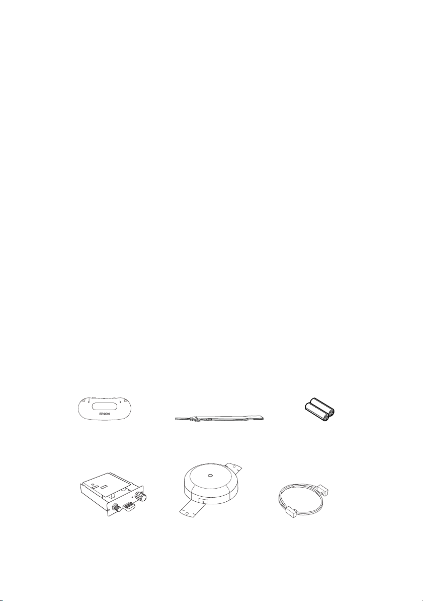
Parts List
Before starting, make sure you have all the parts listed below. If you’re missing any parts,
contact Epson as described on page 16.
Pendant microphone
IR receiver module
Neck strap AA alkaline batteries
Coaxial cableIR dome sensor
Introduction 5
Page 6
Getting Started
Before you can use your pendant microphone, you need to do the following:
■ Install the IR receiver module
■ Install and connect the IR dome sensor
■ Attach the neck strap
■ Insert the batteries
■ Adjust the sound
Install the IR Receiver Module
Follow the steps below to install the IR receiver module. Make sure you have read all of the
safety instructions before beginning the installation.
Note: The Connection & Control Box must be mounted to the wall prior to installation.
See your Connection & Control Box guide for more information.
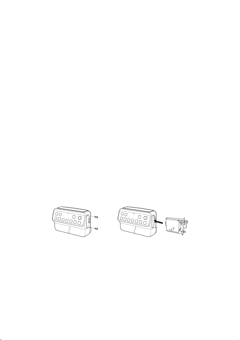
1. Turn off the power to the Connection & Control Box, then disconnect the plug from
the outlet.
2. Remove the two screws from the cover on the side of the Connection & Control Box,
then remove the cover.
3. Insert the IR receiver module into the slot, then reattach the two screws.
4. Connect the plug to the outlet, then turn on the power to the Connection & Control
Box.
5. Verify that the light on the receiver module is lit (red).
Note: If the light on the IR receiver module is not lit, the IR receiver module is not
properly seated.
6 Getting Started
Page 7

Install the IR Dome Sensor
The IR dome sensor is the next thing you’ll need to install. To ensure proper audio
reception, the IR dome sensor should be positioned to have direct line of sight to most
areas of the room. The IR dome sensor should also be mounted in a location free of
obstructions and away from strong light sources. When choosing a location for the IR
dome sensor, keep the following in mind:
■ Do not install the IR dome sensor or coaxial cable near power cables. This can cause
unwanted audio noise or reduce the sensitivity and range of the IR dome sensor.
■ Do not bind the coaxial cable to any other cables.
■ Do not install the IR sensor near strong light sources, such as incandescent bulbs,
halogen lamps, fluorescent lights, or a window.
■ The IR dome sensor must be mounted at least 3.28 feet (1 meter) away from
fluorescent lights.
■ Do not install the IR dome sensor in a dusty environment. This can reduce the
sensitivity and range of the IR dome sensor.
■ Do not paint the cover of the IR dome sensor.
■ The use of IR remote controls of any kind can interrupt the sound or cause noise.
■ The IR dome sensor receives reflected signals from the walls, floor, and ceiling. The
reception may be reduced if the wall, floor, or ceiling colors are dark.
■ The sound may break up if the IR dome sensor is installed near a window or in a
room with a lot of windows. Apply light-colored curtains or blinds to improve the
sound quality.
■ Install the IR dome sensor on a ceiling that is less than 9.8 feet (3 meters) high. If the
ceiling is too high, the IR dome sensor may not be able to receive the microphone’s
signal from directly under the IR dome.
Note: Epson strongly recommends that the IR dome sensor be installed by a
professional audio/video installer or other qualified professional. Epson cannot provide
advice concerning construction practices or building codes in your area.
Locate the following parts:
■ IR dome sensor
■ Coaxial cable
Warni ng: Make sure that the ceiling is strong enough to support the IR dome sensor
and coaxial cable. Epson accepts no responsibility for the IR dome sensor falling due to
insufficient ceiling strength or inadequate installation.
Getting Started 7
Page 8
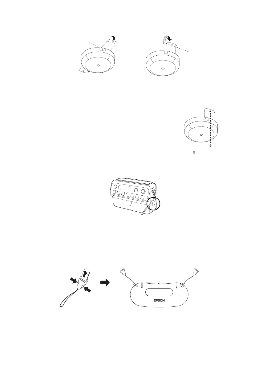
1. Bend both ends of the mounting bracket as shown below.
2. Securely attach the IR dome sensor to the ceiling. Installation varies depending on
your building construction.
3. Attach the coaxial cable to the back of the IR dome
sensor.
4. Secure the coaxial cable to the ceiling.
Note: The coaxial cable can also be run in the ceiling
instead of securing it to the ceiling. For best
performance, keep it away from electrical wires and
florescent lighting.
5. Attach the end of the coaxial cable to the IR receiver module.
Attach the Neck Strap
1. Disconnect both ends of the pendant microphone’s neck strap.
2. Attach the ends of the neck strap to the pendant microphone.
8 Getting Started
Page 9
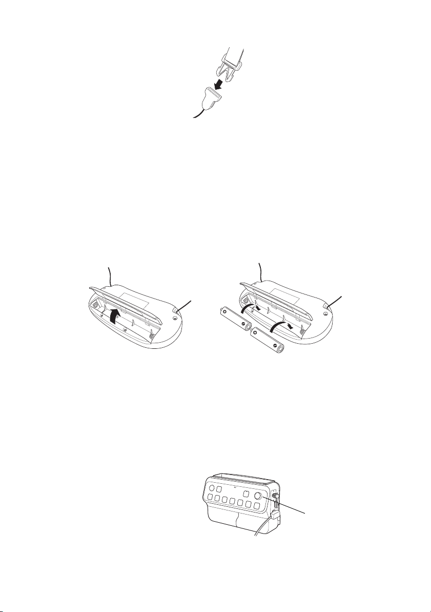
3. Reconnect the ends of the neck strap.
Insert Batteries
If the power button on the pendant microphone turns red or doesn’t illuminate, you may
need to insert or replace the batteries. Follow the steps below to insert batteries in the
pendant microphone.
1. Open the pendant microphone’s battery cover.
2. Check the battery label and insert two AA alkaline batteries into the pendant
microphone.
3. Close the pendant microphone’s battery cover.
Adjust the Sound
Follow the steps in this section to adjust the audio levels.
1. Make sure the Connection & Control Box is on and the green light is lit.
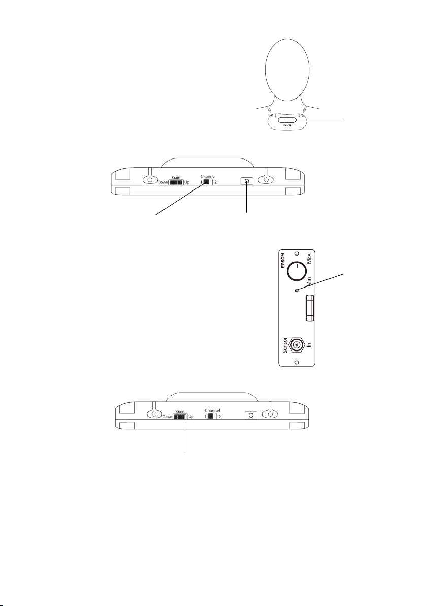
2. Adjust the volume control knob on
the Connection & Control Box to
the far left setting to turn the
volume all the way down.
3. Place the microphone around your
neck with the black emitter facing
away from you.
Volume control knob
Getting Started 9
Page 10
4. Adjust the neck strap so that the top of the
microphone is just below your collarbone.
5. Set the
Channel switch to 1.
Note: The channel must be set to 1 when the
microphone is used with the Connection &
Control Box. Channel 2 is not available.
6. Press the power button until it clicks into place.
The power button turns green.
Power buttonSet to Channel 1
Note: If the power button turns red or doesn’t
illuminate, replace the batteries in the pendant
microphone.
7. Verify that the light on the IR receiver module is lit
(green).
Note: If the light on the IR receiver module is red,
the microphone is not recognized.
8. Adjust the microphone sensitivity by rotating the Gain
control wheel until the white line is next to
Up, but
still visible.
Emitter
IR receiver
light
Note: The sound from the microphone is transmitted from the black dome on the
front of the microphone. Be sure to keep this part of the microphone free of
obstructions when in use.
Audio from the microphone may not be transmitted reliably when the microphone
is used up against a wall or in a corner.
10 Getting Started
White line
Page 11
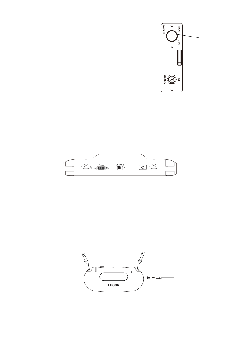
9. Speak normally into the microphone and gradually
increase the gain control knob on the IR receiver
module.
IR receiver
gain control
knob
10. Now you can adjust the volume control on the
Connection & Control Box.
Note: If necessary, you can also adjust the volume on
the speakers and any other audio sources that are
connected.
Connecting External Audio Devices
The pendant microphone allows you to amplify sound from an external audio device, such
as a computer or portable audio device. Follow the steps below to connect your external
audio device to the pendant microphone.
1. Turn off the microphone by pressing the power button.
Power button
2. Plug a 3.5 mm stereo mini cable into the headphone or line out jack on your audio
device.
Note: If your audio device has RCA-style connectors, connect the device using an
RCA to 1/8-inch stereo mini “Y” cable.
3. Plug the other end of the cable into the pendant microphone’s Audio In jack.
4. Turn on the pendant microphone and start playback from your external audio device.
The audio is automatically played through the speakers connected to the Connection
& Control Box via the IR receiver module.
Getting Started 11
Page 12

5. If you need to adjust the volume, use your external audio device’s volume control.
Note: If your audio device doesn’t have a volume control, you can use the
microphone Gain control wheel to adjust the volume from your external audio
device. The Gain control wheel also affects the volume of your voice when using
the pendant microphone. You may need to readjust the microphone sensitivity
when you’re done playing audio from the external audio device.
12 Getting Started
Page 13

Solving Problems
If you have a problem with your pendant microphone kit, check the following sections for
basic troubleshooting suggestions.
Problems and Solutions
There is no sound
■ If you can’t hear audio from the microphone, make sure that the Gain control wheel
on the pendant microphone is set so that the white line is next to Up, but still visible.
■ Try increasing the volume. Depending on your audio source, it’s possible that no
sound may be heard at lower settings.
■ If you’ve connected an external audio device such as an MP3 player, make sure its
volume control is adjusted to allow sound output.
■ Press the Audio Mute button on the Connection & Control Box to make sure the
sound wasn’t muted or turned off.
■ Make sure the Connection & Control Box is turned on.
■ Check to make sure that the pendant microphone’s power button is green. If it’s red or
not lit, replace the batteries.
■ Adjust the Gain control on the pendant microphone to increase the microphone
sensitivity.
■ Make sure that the pendant microphone is positioned with the black emitter window
facing away from you and is free of obstructions.
■ Check the connection of the pendant microphone to the IR reveiver module.
■ Check to see if the IR dome sensor’s red power light is lit. If it’s not, make sure the
cables are connected properly.
My voice isn’t loud enough
■ Adjust the audio levels, see page 9 for details.
■ Adjust the volume on the IR receiver module.
■ Adjust the Microphone gain control knob on the IR receiver module.
Solving Problems 13
Page 14

External audio devices are too loud
■ Use the volume control on the external audio device to decrease the volume of the
external audio device.
■ Adjust the audio levels, see page 9 for details.
I hear feedback (howling)
■ Move the pendant microphone away from the speakers.
■ Turn down the Gain control wheel on the pendant microphone.
■ Turn down the volume on the Connection & Control Box.
■ Turn down the Microphone gain control knob on the IR receiver module.
The power light won’t come on
You may need to replace the pendant microphone’s batteries.
Specifications
Pendant Microphone
Microphone Type Single Directivity Electret Capacitor
Controls Gain Adjustment Thumbwheel
Power Button
Mic Channel Switch (1/2)
Battery Type AA Alkaline (LR6) × 2
Audio Connectors 3.5 mm Stereo Minijack (Aux In)
Frequency Channel 1 = 2.06 MHz
Frequency Response 100~10, 000 Hz
IR luminescence Wavelength: 870 n m
Transmitting Frequency: 2.06 MHz
Dimensions 5.10" × 2.25" × 0.73" (13 × 5.7 × 1.8 cm) (W × D × H)
Weight 2.19 ounces/62 g
Temperature Operating: 41 °F to 95 °F (5 °C to 35 °C)
Humidity Operating: 20% - 80%
14 Solving Problems
Page 15

IR dome sensor
Input Voltage DC 24 V (draws power from IR receiver)
Size 4.0" × 1.2" (10.1 × 3 cm) (not including connector)
Weight 6.17 ounces (175 g)
Temperature Operating: 41 °F to 95 °F (5 °C to 35 °C)
Humidity Operating: 20% - 80%
Cable (coaxial) 3.28' (3 m)
IR Receiver module
Input Voltage DC 24 V
Receiver frequency 2.06 MHz
Temperature Operating: 41 °F to 95 °F (5 °C to 35 °C)
Humidity Operating: 20% - 80%
Environmental
Temperature Operating: 41 to 95 °F (5 to 35 °C)
Storage: 14 to 140 °F (-10 to 60 °C)
Safety Standards
United States UL60065
Canada CAN/CSA-C22.2 No.60065-03
This product is for use in North America only.
Solving Problems 15
Page 16

Where To Get Help
Internet Support
Visit Epson’s support website at www.epson.com/support (U.S.) or www.epson.ca/
support (Canada) and select your product for solutions to common problems. You can
download product documentation, view FAQs, or e-mail Epson with your questions.
Speak to a Support Representative
You may speak with a projector support specialist by dialing one of these numbers:
■ U.S.: (562) 276-4394, 6 AM to 6 PM, Pacific Time, Monday through Friday.
■ Canada: (905) 709-3839, 6 AM to 6 PM, Pacific Time, Monday through Friday.
Days and hours of support are subject to change without notice. Toll or long distance
charges may apply.
Before you call for support, please have the following information ready:
■ Product name (ELPMC02 Pendant Microphone Kit)
■ Product serial number (displayed on the product)
■ Proof of purchase (such as a store receipt) and date of purchase
■ Computer or video configuration
■ Description of the problem
16 Solving Problems
Page 17

Notices
FCC Statement for Verification
This device complies with Part 15 of the FCC Rules. Operation is subject to the following two
conditions: (1) this device may not cause harmful interference, and (2) this device must accept any
interference received, including interference that may cause undesired operation.
For Canadian Users
This Class B digital apparatus complies with Canadian ICES-003.
Cet appareil numérique de la classe B est conforme à la norme NMB-003 du Canada.
Epson America, Inc. Limited Warranty
One-Year Limited Warranty
What Is Covered: Epson America, Inc. (“Epson”) warrants to the original retail purchaser of the
Epson product enclosed with this limited warranty statement that the product, if purchased new and
operated in the United States, Canada, or Puerto Rico will be free from defects in workmanship and
materials for a period of one (1) year from the date of original purchase. For warranty service, you
must provide proof of the date of original purchase.
What Epson Will Do To Correct Problems: If your product requires service during the limited
warranty period, please call Epson at the number on the bottom of this statement and be prepared to
provide the model, serial number, and date of original purchase. Epson will, at its option, repair or
replace the defective unit, without charge for parts or labor. When Epson authorizes an exchange for
the defective unit, Epson will ship a replacement product to you, freight prepaid, so long as you use
an address in the United States, Canada, or Puerto Rico. You are responsible for securely packaging
the defective unit and returning it to Epson within five (5) working days of receipt of the
replacement. Epson requires a debit or a credit card number to secure the cost of the replacement
product in the event that you fail to return the defective one. When warranty service involves the
exchange of the product or of a part, the item replaced becomes Epson property. The exchanged
product or part may be new or refurbished to the Epson standard of quality, and at Epson's option,
the replacement may be another model of like kind and quality. Epson’s liability for replacement of
the covered product will not exceed the original retail selling price of the covered product. Exchange
or replacement products or parts assume the remaining warranty period of the product covered by
this limited warranty.
What This Warranty Does Not Cover: This warranty covers only normal use in the United States,
Canada, or Puerto Rico. Twenty-four hours per day or other excessive continual use is not considered
normal use. This warranty does not cover consumables. This warranty is not transferable. Epson is
not responsible for warranty service should the Epson label or logo or the rating label or serial
number be removed. Epson is not responsible for warranty service should the product fail to be
properly maintained or fail to function properly as a result of misuse, abuse, improper installation,
Notices 17
Page 18

neglect, improper shipping, damage caused by disasters such as fire, flood, and lightning, improper
electrical current, software problems, interaction with non-Epson products, or service other than by
Epson or an Epson Authorized Servicer. Postage, insurance, or shipping costs incurred in presenting
your Epson product for carry-in warranty service are your responsibility. Epson will pay for all freight
charges if you choose to send your unit to Epson for repair. If a claimed defect cannot be identified
or reproduced in service, you will be held responsible for costs incurred.
THE WARRANTY AND REMEDY PROVIDED ABOVE ARE EXCLUSIVE AND IN LIEU OF
ALL OTHER EXPRESS OR IMPLIED WARRANTIES INCLUDING, BUT NOT LIMITED
TO, THE IMPLIED WARRANTIES OF MERCHANTABILITY OR FITNESS FOR A
PARTICULAR PURPOSE. SOME LAWS DO NOT ALLOW THE EXCLUSION OF IMPLIED
WARRANTIES. IF THESE LAWS APPLY, THEN ALL EXPRESS AND IMPLIED
WARRANTIES ARE LIMITED TO THE WARRANTY PERIOD IDENTIFIED ABOVE.
UNLESS STATED HEREIN, ANY STATEMENTS OR REPRESENTATIONS MADE BY ANY
OTHER PERSON OR FIRM ARE VOID. IN THE EVENT THE REMEDIES ABOVE FAIL,
EPSON'S ENTIRE LIABILITY SHALL BE LIMITED TO A REFUND OF THE PRICE PAID
FOR THE EPSON PRODUCT COVERED BY THIS LIMITED WARRANTY. EXCEPT AS
PROVIDED IN THIS WRITTEN WARRANTY, NEITHER EPSON AMERICA, INC. NOR
ITS AFFILIATES SHALL BE LIABLE FOR ANY LOSS, INCONVENIENCE, OR DAMAGE,
INCLUDING DIRECT, SPECIAL, INCIDENTAL, OR CONSEQUENTIAL DAMAGES,
RESULTING FROM THE USE OR INABILITY TO USE THE EPSON PRODUCT,
WHETHER RESULTING FROM BREACH OF WARRANTY OR ANY OTHER LEGAL
THEORY.
In Canada, warranties include both warranties and conditions.
Some jurisdictions do not allow limitations on how long an implied warranty lasts and some
jurisdictions do not allow the exclusion or limitation of incidental or consequential damages, so the
above limitations and exclusions may not apply to you. This warranty gives you specific legal rights,
and you may also have other rights, which vary from jurisdiction to jurisdiction.
To find the Epson Authorized Reseller nearest you, please visit our website at: www.epson.com.
To find the Epson Customer Care Center nearest you, please visit www.epson.com/support.
SM
To contact the Epson Connection
, please call (562) 276-4394 in the U.S. and (905) 709-3839 in
Canada or write to Epson America, Inc., P.O. Box 93012, Long Beach, CA 90809-3012.
18 Notices
Page 19

Copyright Notice
All rights reserved. No part of this publication may be reproduced, stored in a retrieval system, or
transmitted in any form or by any means, electronic, mechanical, photocopying, recording, or
otherwise, without the prior written permission of Seiko Epson Corporation. The information
contained herein is designed only for use with this Epson product. Epson is not responsible for any
use of this information as applied to other products.
Neither Seiko Epson Corporation nor its affiliates shall be liable to the purchaser of this product or
third parties for damages, losses, costs, or expenses incurred by purchaser or third parties as a result
of: accident, misuse, or abuse of this product or unauthorized modifications, repairs, or alterations to
this product, or (excluding the U.S.) failure to strictly comply with Seiko Epson Corporation’s
operating and maintenance instructions.
Seiko Epson Corporation shall not be liable for any damages or problems arising from the use of any
options or any consumable products other than those designated as Original Epson Products or
Epson Approved Products by Seiko Epson Corporation.
Trademarks
Epson is a registered trademark and Epson Exceed Your Vision is a registered logomark of Seiko
Epson Corporation.
Epson Connection is a service mark of Epson America Inc.
General Notice: Other product names used herein are for identification purposes only and may be
trademarks of their respective owners. Epson disclaims any and all rights in those marks.
This information is subject to change without notice.
Notices 19
Page 20

20 Notices
Page 21

Table des matières
Introduction . . . . . . . . . . . . . . . . . . . . . . . . . . . . . . . . . . . . . . . . . . . . . . . . . 22
Consignes de sécurité importantes . . . . . . . . . . . . . . . . . . . . . . . . . . . . . . . . . . . . . . . . 22
Liste des pièces. . . . . . . . . . . . . . . . . . . . . . . . . . . . . . . . . . . . . . . . . . . . . . . . . . . . . . . 25
Démarrage. . . . . . . . . . . . . . . . . . . . . . . . . . . . . . . . . . . . . . . . . . . . . . . . . . . 26
Installation du module de récepteur IR . . . . . . . . . . . . . . . . . . . . . . . . . . . . . . . . . . . . 26
Installation du capteur à IR . . . . . . . . . . . . . . . . . . . . . . . . . . . . . . . . . . . . . . . . . . . . . 27
Fixation de la bretelle . . . . . . . . . . . . . . . . . . . . . . . . . . . . . . . . . . . . . . . . . . . . . . . . . .29
Insertion des piles . . . . . . . . . . . . . . . . . . . . . . . . . . . . . . . . . . . . . . . . . . . . . . . . . . . . 29
Réglage du volume audio. . . . . . . . . . . . . . . . . . . . . . . . . . . . . . . . . . . . . . . . . . . . . . . 30
Connexion de dispositifs audio externes. . . . . . . . . . . . . . . . . . . . . . . . . . . . . . . . . . . . 31
Résolution des problèmes . . . . . . . . . . . . . . . . . . . . . . . . . . . . . . . . . . . . . . 33
Problèmes et solutions . . . . . . . . . . . . . . . . . . . . . . . . . . . . . . . . . . . . . . . . . . . . . . . . . 33
Spécifications. . . . . . . . . . . . . . . . . . . . . . . . . . . . . . . . . . . . . . . . . . . . . . . . . . . . . . . . 34
Où obtenir de l’aide. . . . . . . . . . . . . . . . . . . . . . . . . . . . . . . . . . . . . . . . . . . . . . . . . . . 36
Avis . . . . . . . . . . . . . . . . . . . . . . . . . . . . . . . . . . . . . . . . . . . . . . . . . . . . . . . . 37
Déclaration FCC de vérification . . . . . . . . . . . . . . . . . . . . . . . . . . . . . . . . . . . . . . . . . 37
Garantie limitée d’Epson America, Inc. . . . . . . . . . . . . . . . . . . . . . . . . . . . . . . . . . . . . 37
Avis sur les droits d’auteur . . . . . . . . . . . . . . . . . . . . . . . . . . . . . . . . . . . . . . . . . . . . . .39
Français
21
Page 22

Introduction
La trousse de microphone à bretelle est un accessoire optionnel utilisé avec la boîte de
connexions et de commande (ELPCB01) et les haut-parleurs à fixation murale pour
rehausser la fonctionnalité de votre projecteur Epson. Après avoir installé votre projecteur
et la boîte de connexions et de commande, lisez ce livret pour :
■ installer le module de récepteur IR
■ installer le capteur à IR
■ installer et utiliser le microphone à bretelle
Avant d’utiliser la trousse de microphone à bretelle, lisez sans faute les consignes de sécurité
ci-dessous et conservez-les pour référence ultérieure.
Consignes de sécurité importantes
Veuillez observer les consignes ci-dessous :
Avertissement :
Les avertissements indiquent des consignes concernant la manipulation qu’il faut
observer à la lettre, à défaut de quoi il peut s’ensuivre des blessures, voire la mort.
Mise en garde :
Les mises en garde indiquent des consignes concernant la manipulation qu’il faut
observer à la lettre, à défaut de quoi il peut s’ensuivre des blessures ou des dégâts
matériels.
Remarque :
Les remarques contiennent des informations importantes au sujet de votre
équipement.
Avertissements
■ Ne haussez pas d’emblée le son à un volume trop élevé. Un son bruyant pourrait
retentir soudainement et pourrait endommager votre ouïe. Par mesure de précaution,
baissez le volume avant d’éteindre le système, puis augmentez-le progressivement
après avoir rallumé le système.
■ Epson ne peut être tenue responsable de la chute de composants de ce produit en
raison d’une solidité insuffisante de l’installation au plafond ou d’une installation
inadéquate.
22 Introduction
Page 23

■ Ne laissez pas le système ou le microphone à bretelle avec les piles dans un véhicule
dont les vitres des portières sont fermées, dans des endroits où ils seraient exposés à la
lumière directe du soleil ou dans d’autres endroits susceptibles de devenir
extrêmement chauds. Il pourrait s’ensuivre une déformation thermique ou une
défaillance technique pouvant entraîner un feu.
■ Assurez-vous que les boulons, les vis et les écrous sont bien serrés une fois l’installation
terminée. Assurez-vous que le matériel est fixé solidement, sinon le système pourrait
tomber et causer de sérieuses blessures.
■ Soyez conscient de la bretelle lorsque vous utilisez le microphone à bretelle. La bretelle
pourrait se rompre si vous la manipulez avec force.
■ Ne tirez jamais sur la bretelle quand elle est suspendue à votre cou. Cela pourrait
entraîner des blessures ou un accident.
Mises en garde
■ Débranchez la boîte de connexions et de commande de la prise murale avant le
nettoyage. Vous éviterez ainsi les chocs électriques pendant le nettoyage.
■ Débranchez la boîte de connexions et de commande de la prise murale et adressez-
vous à un technicien qualifié dans les cas suivants :
■ s’il émane du système de la fumée ou des odeurs ou des bruits inhabituels.
■ si du liquide ou des corps étrangers se sont infiltrés dans le système.
■ si le système est tombé ou que son boîtier a été endommagé.
L’utilisation continue sous ces conditions peut résulter en un feu ou un choc
électrique.
■ N’utilisez pas le système dans des endroits où il y a de l’humidité ou de la poussière
excessive, près d’appareils de cuisson ou de chauffage ou encore dans des endroits où le
système pourrait être exposé à la fumée ou à la vapeur.
■ L’utilisation non indiquée d’une pile peut causer la fuite de liquide de pile et sa
rupture, ce qui pourrait entraîner un feu, des blessures ou la corrosion du système.
Lorsque vous remplacez les piles, observez les consignes suivantes :
■ Insérez les piles en respectant la polarité (+ et -).
■ N’utilisez pas des piles de types différents ou des piles vieilles et neuves ensemble.
■ N’utilisez pas des piles autres que celles spécifiées dans ce guide.
■ En cas de fuite d’une pile, essuyez le liquide avec un chiffon doux. Si vos mains
viennent en contact avec le liquide, lavez-les immédiatement.
■ Remplacez les piles dès qu’elles sont épuisées.
Introduction 23
Page 24

■
Retirez les piles si vous ne prévoyez pas utiliser le système pendant une période
prolongée.
■ N’exposez pas les piles à la chaleur ou aux flammes et ne les mettez pas dans l’eau.
■ Éliminez les piles usées conformément à la réglementation locale.
■ Conservez les piles hors de la portée des enfants. Les piles représentent un risque
d’étouffement et leur ingestion est très dangereuse.
Consultez votre réglementation provinciale et locale concernant l’élimination
appropriée des piles.
■ Ne desserrez jamais des boulons, vis ou écrous après l’installation. Vérifiez aussi
périodiquement qu’ils ne se sont pas desserrés. Si une fixation est desserrée, resserrez-la
fermement.
■ Avant de déplacer le système, assurez-vous que la boîte de connexions et de
commande est hors tension, que sa fiche est débranchée de la prise et que tous les
câbles sont déconnectés, au risque de provoquer un feu ou un choc électrique.
■ N’utilisez pas et ne rangez pas le système à des températures trop élevées ou basses.
Évitez les endroits où la température change fréquemment ou rapidement.
Autres consignes de sécurité
■ N’installez pas ce produit dans des endroits soumis à des chocs ou vibrations.
■ Ne démontez ou ne modifiez jamais le produit de quelque manière que ce soit. Des
tensions électriques dangereuses à l’intérieur des composants peuvent causer des
blessures graves.
■ Faites attention de ne pas vous pincer les doigts quand vous installez l’unité du
récepteur IR dans la boîte de connexions et de commande.
■ Utilisez pour le nettoyage un chiffon sec (ou, pour les taches tenaces, un chiffon
humide bien essoré). N’utilisez pas de nettoyants liquides ou en aérosol ou des
solvants comme de l’alcool, du diluant ou de la benzine.
■ Une fois son utilisation terminée, éteignez votre microphone.
24 Introduction
Page 25

Liste des pièces
Avant de commencer, vérifiez que vous avez toutes les pièces listées ci-après. S’il vous
manque des pièces, contactez Epson tel que décrit à la page 36.
Microphone à bretelle
Module de
récepteur IR
Bretelle Piles alcalines AA
Câble coaxialCapteur à IR
Introduction 25
Page 26

Démarrage
Avant de pouvoir utiliser votre microphone à bretelle, vous avez besoin de faire ce qui suit :
■ installer le module de récepteur IR
■ installer et connecter le capteur à IR
■ fixer la bretelle
■ insérer les piles
■ régler le son
Installation du module de récepteur IR
Pour installer le module de récepteur IR, procédez comme ci-après. Lisez sans faute toutes
les consignes de sécurité avant de commencer l’installation.
Remarque : La boîte de connexions et de commande doit être montée au mur avant
l’installation. Pour obtenir plus d’information, consultez votre guide de boîte de
connexions et de commande.
1. Éteignez la boîte de connexions et de commande, puis débranchez la fiche de la prise
murale.
2. Retirez les deux vis du couvercle sur le côté de la boîte de connexions et de
commande, puis retirez le couvercle.
3. Insérez le module de récepteur IR dans le logement, puis réinstallez les deux vis.
4. Branchez la fiche dans la prise murale, puis allumez la boîte de connexions et de
commande.
5. Vérifiez que le témoin du module de récepteur est allumé (rouge).
Remarque : Si le témoin du module de récepteur IR n’est pas allumé, le module de
récepteur IR n’est pas correctement installé.
26 Démarrage
Page 27

Installation du capteur à IR
Le capteur à IR est le prochain composant à installer. Pour assurer une bonne réception
audio, le capteur à IR doit être positionné de manière à se trouver en ligne de visée directe
avec la plupart des zones de la salle. Le capteur à IR doit aussi être monté dans un
emplacement exempt d’obstructions et à l’écart de sources d’éclairage intense. Observez les
consignes suivantes pour sélectionner un emplacement pour le capteur à IR :
■ N’installez pas le capteur à IR ou le câble coaxial près de câbles d’alimentation. Cela
peut causer du bruit indésirable ou réduire la sensibilité et la portée du capteur à IR.
■ N’attachez pas le câble coaxial à tout autre câble.
■ N’installez pas le capteur à IR près de sources d’éclairage intense (comme des
ampoules incandescentes, des ampoules à halogène, des éclairages fluorescents) ou
d’une fenêtre.
■ Le capteur à IR doit être monté à une distance d’au moins 1 mètre (3,28 pi) des
éclairages fluorescents.
■ N’installez pas le capteur à IR dans un environnement poussiéreux. Cela peut réduire
la sensibilité et la portée du capteur à IR.
■ Ne peinturez pas le couvercle du capteur à IR.
■ L’utilisation d’une télécommande à IR, quel qu’en soit le type, peut couper le son ou
produire du bruit.
■ Le capteur à IR capte les signaux réfléchis des murs, du plancher et du plafond. La
réception peut être réduite si les couleurs du mur, du plancher et du plafond sont
sombres.
■ Le son peut être rompu si le capteur à IR est installé à proximité d’une fenêtre ou dans
une salle généreusement fenêtrée. Envisagez l’installation de rideaux ou de stores de
couleur pâle pour améliorer la qualité du son.
■ Installez le capteur à IR sur un plafond d’une hauteur maximum de 3 mètres (9,8 pi).
Si le plafond est trop haut, il se peut que le capteur à IR ne soit pas en mesure de
capter le signal du microphone directement sous le capteur à IR.
Remarque : Epson recommande vivement de confier l’installation du capteur à IR à un
installateur audio/vidéo professionnel ou autre professionnel qualifié. Epson ne peut
fournir de conseils concernant les pratiques en matière de construction ou les codes de
bâtiment en vigueur dans votre localité.
Démarrage 27
Page 28

Localisez les pièces suivantes :
■ Capteur à IR
■ Câble coaxial
Avertissement : Assurez-vous que le plafond est suffisamment solide pour soutenir le
capteur à IR et le câble coaxial. Epson ne peut être tenue responsable de la chute du
capteur à IR en raison de la solidité insuffisante du plafond ou d’une installation
inadéquate.
1. Pliez les deux extrémités du support de montage tel que montré ci-dessous.
2. Fixez solidement le capteur à IR sur le plafond. L’installation varie selon la
construction de votre bâtiment.
3. Fixez le câble coaxial sur le dos du capteur à IR.
4. Fixez le câble coaxial sur le plafond.
Remarque : Il est aussi possible de passer le câble
coaxial dans le plafond plutôt que de le fixer sur le
plafond. Pour une performance optimale, tenez-le à
l’écart des fils électriques ou d’éclairage fluorescent.
5. Fixez l’extrémité du câble coaxial sur le module de
capteur à IR.
28 Démarrage
Page 29

Fixation de la bretelle
1. Déconnectez les deux extrémités de la bretelle du microphone.
2. Fixez les extrémités de la bretelle sur le microphone.
3. Reconnectez les extrémités de la bretelle.
Insertion des piles
Si le bouton d’alimentation du microphone à bretelle passe au rouge ou ne s’allume pas,
vous pourriez avoir besoin d’insérer ou de remplacer les piles. Suivez les étapes ci-dessous
pour insérer les piles du microphone à bretelle.
1. Ouvrez le couvercle du compartiment à piles du microphone à bretelle.
2. Vérifiez l’étiquette des piles et insérez les deux piles alcalines AA dans le microphone à
bretelle.
3. Ouvrez le couvercle du compartiment à piles du microphone.
Démarrage 29
Page 30

Réglage du volume audio
Suivez les étapes de cette section pour ajuster les niveaux audio.
1. Assurez-vous que la boîte de connexions et de commande est allumée et que le témoin
vert est allumé.
2. Tournez la molette de commande
de volume de la boîte de
connexions et de commande
complètement à gauche pour
baisser le volume à fond.
3. Portez le microphone autour du
cou avec l’émetteur noir orienté vers l’extérieur.
4. Ajustez la bretelle de sorte que le haut du
microphone se trouve juste sous votre clavicule.
5. Réglez le commutateur
Remarque : Le canal doit être réglé sur 1
quand le microphone est utilisé avec la boîte de
connexions et de commande. Le canal 2 n’est
pas disponible.
Channel à 1.
6. Appuyez sur le bouton d’alimentation jusqu’au
déclic. Le bouton d’alimentation passe au vert.
Molette de commande
du volume
Émetteur
Remarque : Si le bouton d’alimentation passe au
rouge ou ne s’allume pas, remplacez les piles du
microphone à bretelle
.
7. Vérifiez que le témoin du module du récepteur IR est
allumé (vert).
Remarque : Si le témoin du module de récepteur IR
est rouge, le microphone n’est pas reconnu.
30 Démarrage
Bouton d’alimentationRéglez sur Channel 1
Témoin de
récepteur
IR
Page 31

8. Réglez la sensibilité du microphone en tournant la molette
ligne blanche soit près de
Remarque : Le son du microphone est transmis du dôme noir à l’avant du
microphone. Assurez-vous que cette partie du microphone est exempte
d’obstructions au cours de son utilisation.
La transmission audio peut ne pas être fiable quand le microphone est utilisé
contre un mur ou dans un coin.
Up, mais toujours visible.
Ligne blanche
Gain jusqu’à ce que la
9. Parlez normalement dans le microphone et augmentez
progressivement la molette de commande de gain du
module de récepteur IR.
10. Vous pouvez également régler le volume au moyen de
la boîte de connexions et de commande.
Remarque : Au besoin, vous pouvez aussi régler le
volume des haut-parleurs et de toute autre source audio
connectée.
Molette de
commande
de gain de
récepteur IR
Connexion de dispositifs audio externes
Le microphone à bretelle vous permet d’amplifier le son d’un dispositif audio externe,
comme un ordinateur ou un dispositif audio portable. Observez les étapes ci-dessous pour
connecter votre dispositif audio externe au microphone à bretelle.
1. Désactivez le microphone en appuyant sur le bouton d’alimentation.
Bouton d’alimentation
Démarrage 31
Page 32

2. Branchez un câble mini stéréo de 3,5 mm dans le casque d’écoute ou la prise de sortie
de ligne de votre dispositif audio.
Remarque : Si votre dispositif audio a des connecteurs de style RCA, branchez le
dispositif au moyen d’un câble en Y RCA/mini stéréo de 1/8 de po.
3. Branchez l’autre extrémité du câble dans la prise Audio In du microphone.
4. Allumez le microphone à bretelle et lancez la lecture de votre dispositif audio externe.
L’audio est transmise automatiquement par les haut-parleurs connectés à la boîte de
connexions et de commande via le module de récepteur IR.
5. Si vous avez besoin de régler le volume, utilisez la commande de volume du dispositif
audio externe.
Remarque : Si votre dispositif audio n’a pas de commande de volume, vous
pouvez utiliser la molette de commande Gain du microphone pour régler le volume
de votre dispositif audio externe. La molette de commande Gain affecte aussi le
volume de votre voix quand vous utilisez le microphone à bretelle. Vous pourriez
avoir besoin de réajuster la sensibilité du microphone quand vous avez terminé de
jouer l’audio de votre dispositif audio externe.
32 Démarrage
Page 33

Résolution des problèmes
Si vous avez un problème avec la trousse de microphone à bretelle, consultez l’une des
sections suivantes pour les procédures de dépannage de base.
Problèmes et solutions
Pas de son
■ Si vous n’entendez pas l’audio du microphone, assurez-vous que la molette de
commande Gain du microphone à bretelle est réglée de sorte que la ligne blanche soit
près de Up, tout en étant toujours visible.
■ Essayez d’augmenter le volume. Selon votre source audio, il se peut qu’aucun son ne
soit émis à des réglages de volume bas.
■ Si vous avez connecté un dispositif audio externe comme un lecteur MP3, assurez-
vous que sa commande de volume est réglée pour permettre une sortie audio.
■ Appuyez sur la touche Audio Mute sur la boîte de connexions ou de commande pour
vous assurer que le son n’était pas mis en sourdine ou désactivé.
■ Assurez-vous que la boîte de connexions et de commande est sous tension.
■ Assurez-vous que le bouton d’alimentation du microphone à bretelle est vert. S’il est
rouge ou s’il n’est pas allumé, remplacez les piles.
■ Réglez la molette de commande Gain du microphone à bretelle pour augmenter la
sensibilité du microphone.
■ Assurez-vous que le microphone à bretelle est positionné avec l’émetteur noir orienté
vers l’extérieur et est libre de toute obstruction.
■ Vérifiez le raccordement du microphone à bretelle au module de récepteur IR.
■ Vérifiez si le témoin d’alimentation rouge du capteur à IR est allumé ou non. S’il ne
l’est pas, assurez-vous que les câbles sont connectés correctement.
Ma voix n’est pas suffisamment forte
■ Réglez les niveaux audio, voyez la page 30 pour les détails.
■ Réglez le volume du module de récepteur à IR.
■ Baissez la molette de commande de gain du microphone sur le module de récepteur
IR.
Résolution des problèmes 33
Page 34

Les dispositifs audio externes sont trop bruyants
■ Utilisez la commande de volume du dispositif audio externe pour baisser le volume du
dispositif audio externe.
■ Réglez les niveaux audio, voyez la page 30 pour les détails.
J’entends une rétroaction (réaction acoustique)
■ Déplacez le microphone à bretelle loin des haut-parleurs.
■ Baissez le réglage de la molette de commande Gain du microphone à bretelle.
■ Baissez le volume sur la boîte de connexions et de commande.
■ Baissez la molette de commande de gain du module de récepteur IR.
Le témoin d’alimentation ne s’allume pas
Il peut être nécessaire de remplacer les piles de la télécommande.
Spécifications
Microphone à bretelle
Type de microphone Capacité électret à simple directivité
Commandes Molette de réglage de gain
Bouton d’alimentation
Interrupteur de canal mic (1/2)
Type de pile Alcaline AA (LR6) × 2
Connecteurs audio Mini-prise stéréo de 3,5 mm (entrée aux.)
Fréquence Canal 1 = 2,06 MHz
Réponse de fréquence 100~10, 000 Hz
Luminescence IR Longueur d’onde : 870 n m
Fréquence d’émission : 2,06 MHz
Dimensions 5,10 po × 2,25 po × 0,73 po (13 cm × 5,7 cm × 1,8 cm)
(l × p × h)
Poids 62 g (2,19 oz)
Température Fonctionnement : 41 °F à 95 °F (5 °C à 35 °C)
34 Résolution des problèmes
Page 35

Humidité Fonctionnement : 20% - 80%
Capteur à IR
Tension d’entrée 24 V CC (alimentation via le récepteur IR)
Dimensions 4,0 po × 1,2 po (10,1 cm × 3 cm) (connecteur non inclus)
Poids 175 g (6,17 oz)
Température Fonctionnement : 41 °F à 95 °F (5 °C à 35 °C)
Humidité Fonctionnement : 20% - 80%
Câble (coaxial) 3,28 pi (3 m)
Module de récepteur IR
Tension d’entrée DC 24 V
Fréquence du récepteur 2,06 MHz
Température Fonctionnement : 41 °F à 95 °F (5 °C à 35 °C)
Humidité Fonctionnement : 20% - 80%
Caractéristiques environnementales
Température Fonctionnement : 5 à 35 °C (41 à 95 °F)
Entreposage :
–10 à 60 °C (14 à 140 °F)
Normes de sécurité
États-Unis UL60065
Canada CAN/CSA-C22.2 No.60065-03
Ce produit a été conçu exclusivement pour le marché nord-américain.
Résolution des problèmes 35
Page 36

Où obtenir de l’aide
Assistance Internet
Visitez le site Web de soutien d’Epson à www.epson.ca/support et sélectionnez votre
produit pour obtenir des solutions à des problèmes courants. Vous pouvez télécharger de la
documentation sur les produits, consulter la foire aux questions ou envoyer un courrier
électronique à un représentant du soutien qui répondra à vos questions (site Web présenté
uniquement en anglais).
Pour parler à un représentant du soutien technique
Vous pouvez parler à un spécialiste en matière de projecteurs en composant l’un des
numéros suivants :
■ É.-U. : (562) 276-4394, 6 h à 18 h, heure du Pacifique, du lundi au vendredi.
■ Canada : (905) 709-3839, 6 h à 18 h, heure du Pacifique, du lundi au vendredi.
Les jours et les heures de soutien peuvent être modifiés sans préavis. Des frais d’interurbain
peuvent s’appliquer.
Avant de communiquer avec Epson, ayez les informations suivantes sous la main :
■ Nom du produit (trousse de microphone à bretelle ELPMC02)
■ Numéro de série du produit (affiché sur le produit)
■ Preuve d’achat (telle qu’un reçu de magasin) et date d’achat
■ Configuration informatique ou vidéo
■ Description du problème
36 Résolution des problèmes
Page 37

Avis
Déclaration FCC de vérification
Ce dispositif est conforme à la partie 15 de la réglementation FCC. Le fonctionnement est soumis
aux deux conditions suivantes : 1) cet appareil ne doit pas provoquer d’interférences néfastes, et 2)
cet appareil doit tolérer les interférences reçues, y compris celles qui risquent de provoquer un
fonctionnement indésirable.
Pour les utilisateurs au Canada
This Class B digital apparatus complies with Canadian ICES-003.
Cet appareil numérique de la classe B est conforme à la norme NMB-003 du Canada.
Garantie limitée d’Epson America, Inc.
Garantie limitée de un an
Ce que couvre la garantie : Epson America, Inc. («Epson») garantit à l’acheteur original du produit
Epson couvert par la présente garantie limitée, que le projecteur, s’il est acheté à l’état neuf et utilisé
au Canada, aux États-Unis ou à Porto Rico, sera exempt de défaut de fabrication et de vice de
matériau pendant une durée de un (1) an à compter de la date d’achat d’origine. Pour toute
intervention au titre de la garantie, vous devez fournir la preuve de la date d’achat d’origine.
Ce que fera Epson pour remédier aux problèmes : Si votre produit doit être réparé durant la période où
il est couvert par la garantie limitée, veuillez appeler Epson au numéro inscrit dans le bas de cette
déclaration et assurez-vous d’être en mesure de fournir le modèle, le numéro de série et la date
d’achat d’origine. Epson pourra, à son choix, réparer ou remplacer l’appareil défectueux sans frais de
pièces ou de main d’œuvre. Quand Epson autorise le remplacement du produit défectueux, Epson
vous enverra un produit de remplacement, en port payé si vous utilisez une adresse au Canada ou aux
États-Unis ou à Porto Rico. Il vous incombe d’emballer correctement l’appareil défectueux et de le
retourner à Epson dans un délai de cinq (5) jours ouvrables après avoir reçu l’unité de remplacement.
Epson vous demandera un numéro de carte de crédit ou de débit pour couvrir le coût du produit de
remplacement au cas où vous ne retourneriez pas le produit défectueux. Lorsqu’une intervention au
titre de la garantie nécessite l’échange du produit ou d’une pièce, l’article remplacé devient propriété
d’Epson. Le produit ou la pièce de rechange pourront être neufs ou remis à neuf selon les normes de
qualité d’Epson et, au choix d’Epson, le produit de remplacement peut être un autre modèle de type
et de qualité semblables. La responsabilité d’Epson pour le remplacement du produit couvert par la
présente garantie ne peut dépasser le prix de vente d’origine du produit couvert. Les produits et
pièces de rechange sont couverts pour la période de garantie restante du produit couvert par la
présente garantie limitée.
Ce que la garantie ne couvre pas : Cette garantie ne s’applique qu’aux États-Unis, au Canada et à Porto
Rico dans le contexte d’une utilisation normale. Une utilisation vingt-quatre heures sur vingt-quatre
ou toute autre utilisation continue ou excessive n’est pas considérée comme une utilisation normale.
Avis 37
Page 38

Cette garantie ne couvre pas les consommables. Cette garantie n’est pas transférable. Epson ne sera
pas tenue d’effectuer d’intervention au titre de la garantie lorsque l’étiquette ou le logo Epson, le
numéro de série ou la plaque signalétique ont été enlevés de l’appareil. Epson ne sera pas tenue
d’effectuer d’intervention au titre de la garantie si le produit n’est pas correctement entretenu ou ne
fonctionne pas correctement en raison d’une mauvaise utilisation, d’une utilisation abusive, d’une
installation incorrecte, d’une négligence, d’avaries lors du transport, de dommages causés par un
incendie, une inondation, la foudre, une surtension électrique, des problèmes logiciels, une
interaction avec des produits de marque autre qu’Epson ou d’une intervention effectuée par un tiers
autre qu’Epson ou un prestataire de service Epson agréé. Les frais d’affranchissement, d’assurance ou
d’expédition engagés pour faire réparer votre produit Epson au titre de la garantie avec retour en
atelier seront à votre charge. Epson défraiera tous les frais de transport si vous choisissez d’envoyer
votre unité à Epson pour effectuer les réparations. Si une anomalie déclarée ne peut être identifiée ou
reproduite, les frais engagés seront à votre charge.
CE QUI PRÉCÈDE CONSTITUE LA SEULE GARANTIE ET EXCLUT TOUTE AUTRE
GARANTIE, EXPRESSE OU IMPLICITE, Y COMPRIS, MAIS SANS S’Y LIMITER, TOUTE
GARANTIE IMPLICITE DE QUALITÉ MARCHANDE, DE NON-VIOLATION OU
D’APTITUDE À UNE FIN PARTICULIÈRE. CERTAINES LOIS N’AUTORISENT PAS
L’EXCLUSION DES GARANTIES IMPLICITES. SI CES LOIS S’APPLIQUENT À VOUS,
TOUTES LES GARANTIES EXPRESSES OU IMPLICITES SE LIMITENT À LA PÉRIODE
DE GARANTIE DÉFINIE CI-DESSUS. SAUF DISPOSITIONS CONTRAIRES, TOUTE
DÉCLARATION OU GARANTIE FAITE PAR UNE AUTRE PERSONNE OU SOCIÉTÉ EST
NULLE. EN CAS D’ÉCHEC DU RECOURS CI-DESSUS, LA SEULE RESPONSABILITÉ
D’EPSON SERA LIMITÉE À UN REMBOURSEMENT DU PRIX PAYÉ POUR LE PRODUIT
EPSON COUVERT PAR LA PRÉSENTE GARANTIE LIMITÉE. SAUF DISPOSITIONS
CONTRAIRES DANS CETTE GARANTIE ÉCRITE, NI EPSON AMERICA, INC. NI SES
FILIALES NE POURRONT ÊTRE TENUES RESPONSABLES EN CAS DE PERTE,
INCONVÉNIENTS OU DOMMAGES, Y COMPRIS LES DOMMAGES DIRECTS,
SPÉCIAUX, ACCESSOIRES OU INDIRECTS DÉCOULANT DE L’UTILISATION OU DE
L’IMPOSSIBILITÉ D’UTILISATION DU PRODUIT EPSON, QUE CE SOIT À LA SUITE
DU NON-RESPECT DE LA GARANTIE OU D’UNE AUTRE THÉORIE JURIDIQUE.
Au Canada, les garanties englobent les garanties et les conditions.
Certains territoires n’autorisant pas les limitations qui s’appliquent à la durée d’une garantie implicite
et d’autres n’autorisant pas l’exclusion ou la limitation des dommages accessoires ou indirects, il est
possible que les limitations et exclusions ci-dessus ne s’appliquent pas à vous. La présente garantie
vous donne des droits juridiques spéciaux auxquels peuvent s’ajouter d’autres droits pouvant varier
d’un territoire à l’autre.
Pour trouver le revendeur Epson autorisé le plus près, visitez notre site Web à : www.epson.ca.
Pour obtenir les coordonnées du centre de service agréé Epson le plus près de vous, veuillez visiter le
site Web www.epson.ca/support.
MS
Pour contacter Epson Connection
, composez le (562) 276-4394 aux É.-U. et le (905) 709-3839
au Canada ou écrivez à Epson America, Inc., P.O. Box 93012, Long Beach, CA 90809-3012.
38 Avis
Page 39

Avis sur les droits d’auteur
Tous droits réservés. Il est interdit de reproduire, de conserver dans un système central ou de
transmettre le contenu de cette publication sous quelque forme et par quelque moyen que ce soit –
reproduction électronique ou mécanique, photocopie, enregistrement ou autre – sans la permission
écrite préalable de Seiko Epson Corporation. L’information contenue dans la présente ne peut être
utilisée qu’avec ce produit Epson. Epson ne peut être tenue responsable de l’utilisation de ces
renseignements pour faire fonctionner d’autres équipements.
Ni Seiko Epson Corporation ni ses filiales ne sauraient être tenues responsables vis-à-vis de l’acheteur
de ce produit, ou de tiers, des dommages, pertes, frais ou dépenses découlant : d’un accident, d’une
utilisation incorrecte ou abusive, de modifications non autorisées, de réparations ou (à l’exception
des États-Unis) du non-respect des directives d’utilisation ou d’entretien de Seiko Epson
Corporation.
Seiko Epson Corporation décline toute responsabilité en cas de dommages ou de problèmes
découlant de l’utilisation d’options ou de produits consommables autres que les produits désignés
comme produits Epson d’origine ou comme produits approuvés pour Epson par Seiko Epson
Corporation.
Marques de commerce
Epson est une marque déposée et Epson Exceed Your Vision est un logotype enregistré de Seiko
Epson Corporation.
Epson Connection est une marque de service d’Epson America, Inc.
Avis général : Les autres noms de produit figurant dans le présent document ne sont cités qu’à titre
d’identification et peuvent être des marques de commerce de leurs propriétaires respectifs. Epson
renonce à tous les droits associés à ces marques.
L’information contenue dans le présent document peut être modifiée sans préavis.
© 2011 Epson America, Inc. 3/11
Avis 39
Page 40

CPD-34260
Printed in XXX/Pays d’impression : XXXXXX
 Loading...