

Page 1
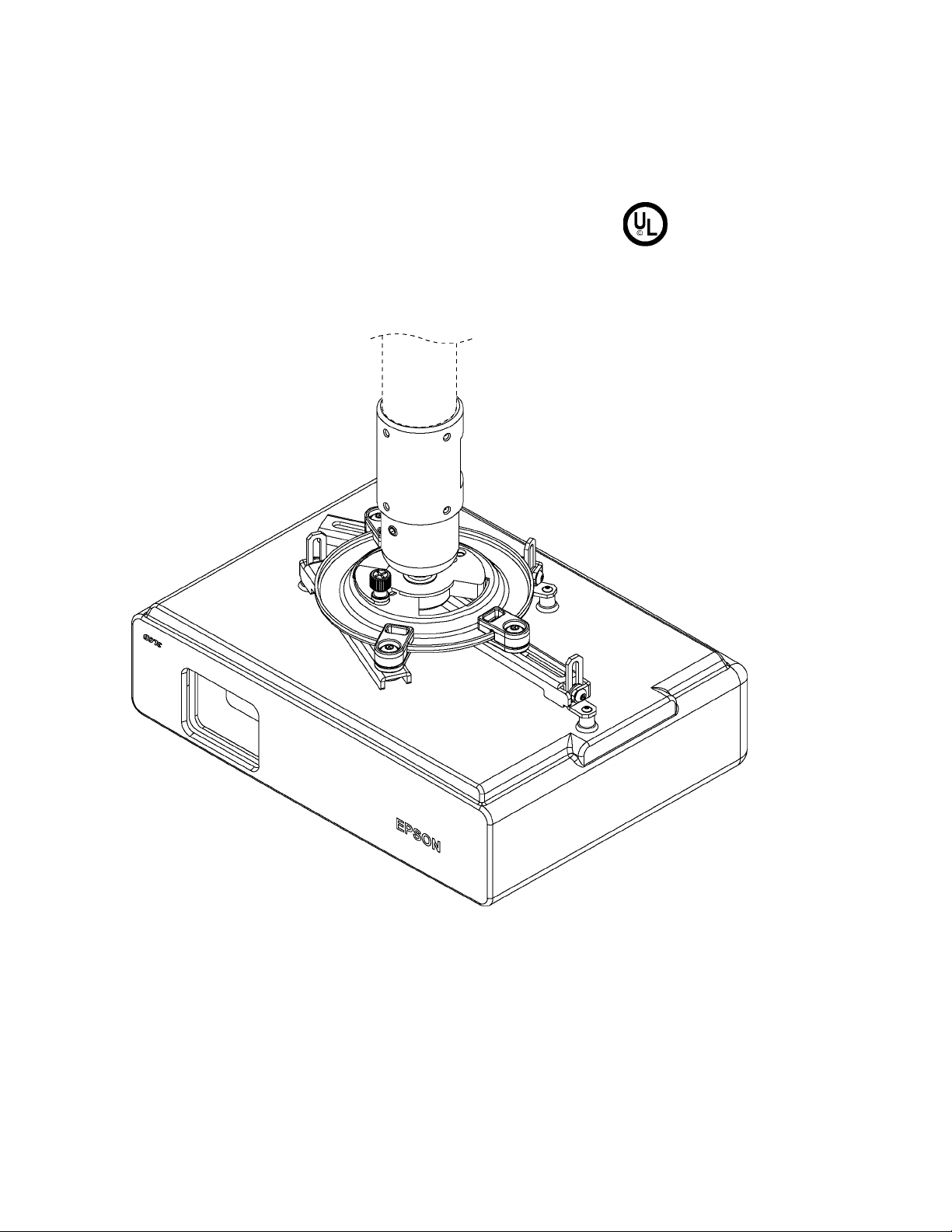
Installation and Assembly:
Universal Projector Ceiling Mount
Model: ELPMBPJF
This product is UL Listed. It must be
installed by a qualihed professional
C
US installer.
Maximum UL Load Capacity: 50 lb (22.7 kg)
Manufactured by Peerless Industries, Inc.
3215W.North Ave. • MelrosePark,IL 60160 • (800)865-2112or(708)865-8870 • Fax:(708)865-2941 • www.peerlessmounts.com
Page 2

NOTE: Read entire instruction sheet before you start instaiiation and assembiy.
A WARNING
Do not begin to instaii your product untii you have read and understood the instructions and warnings contained in
this Instaiiation Sheet. If you have any questions regarding any of the instructions or warnings, caii Peeriess cus
tomer care at 1-800-729-0307.
This product shouid oniy be instaiied by someone of good mechanicai aptitude, has experience with basic buiiding
construction, and fuiiy understands these instructions.
Make sure that the supporting surface wiii safeiy support the combined ioad ofthe equipment and aii attached hard
ware and components.
Never exceed the Maximum UL Load Capacity.
Aiways use an assistant or mechanicai iifting equipment to safeiy iift and position equipment.
This product is intended for indoor use oniy. Use of this product outdoors couid iead to product faiiure and personai
injury.
Tighten screws firmiy, but do not overtighten. Overtightening can damage the items, greatiy reducing their hoiding
power. See suggested torque vaiues where appiicabie within these instructions.
When instaiiing or adjusting the ceiiing mount, do not use adhesives, iubricants, or oiis to prevent the screws from
ioosening. Ifyou use adhesives, iubricants, or oiis to prevent the screws from ioosening, the casing may crack and
the projector may faii, causing serious injury and damage to the projector.
Tools Needed for Assembly
• stud finder ("edge to edge" stud finder is recommended)
• phiiiips screwdriver
• driii
• 1/4" bit for concrete surface
• 5/32" bit for wood joist
Table of Contents__________________
Parts List.............................................................
Instaiiation to Extension Coiumn
Instaiiation to Wood Joist Ceiiings
Instaiiation to Concrete Ceiiings..........................
Fiush Mount Appiication......................................
Attaching Adapter Piate to Projector
Attaching Adapter Piate to Projector Mount.
Projector Aiignment and Accessories..................
Warranty Information
...........................................
.........................
......................
...................
...
...
...
....
...
7-8
...
...
.. 10
3
4
5
6
7
8
9
Visit the Peeriess Web Site atwww.peeriessmounts.com ForTechnicai Support Contact Peeriess Mounts at 1-800-729-0307 or708-865-8870.
2 oflO
ISSUED:01-23-07 SHEET #:055-9498-4 05-20-10
Page 3
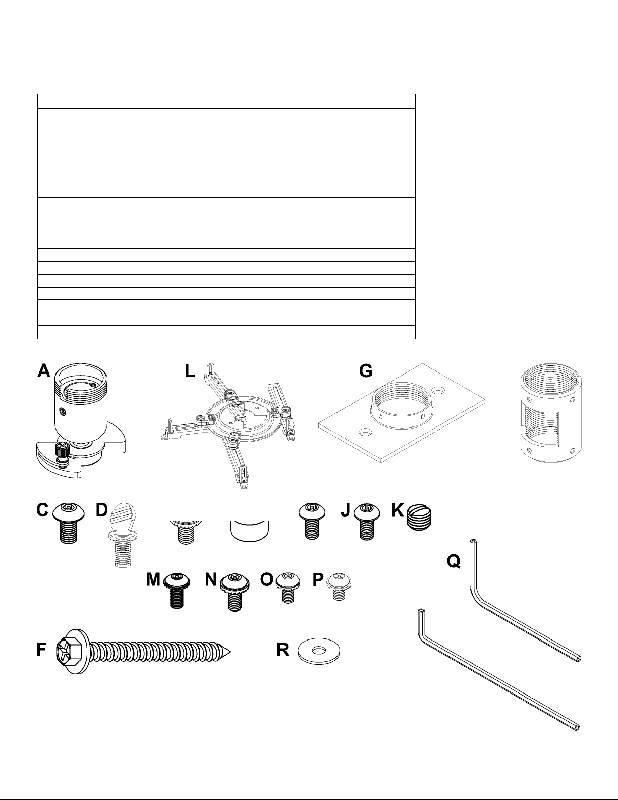
Before you start check the parts list to ensure all of the parts shown are included.
Parts List
Description
A projector mount 1
B 4 mm security allen wrench 1
M5x.8x10 mm socket pin type F screw 1
C
D #10-32 x 3/8" spade thumb screw 1 560-2107
E #10-32 x 3/8" serrated washer head socket pin screw 1
F #14 x 2.5" phillips hex head wood screw 2 5S1-015-C04
ceiling plate 1 580-4042
G
H
.25"IDx.56" ODx.26 spacer
1 extension column connectorwith cord management 1
#10-32 x 3/8" socket pin screw 2 520-2084
J
K #10-32 x 3/16" slotted set screw
L adapter plate 1
M M3x8 mm serrated washer head socket pin screw 4 510-2004
N M4x10 mm serrated washer head socket pin screw 4
M5x10 mm serrated washer head socket pin screw 4
0
P M6x10 mm serrated washer head socket pin screw 4
2 mm security allen wrench 1 560-1097
Q
R washer 4
NOTE: Actual parts may appearslightly different than illustrated.
Qty.
2
3
Part Number
055-0016
560-9646
520-2031
520-2151
590-2071
580-4025
520-2187
055-KUNV-S-3
510-2060
510-2063
510-2066
540-2025
B
Visit the Peerless Web Site atwww.peerlessmounts.com For Technical Support Contact Peerless Mounts at 1-800-729-0307 or708-865-8870.
3 of10
ISSUED:01-23-07 SHEET #:055-9498-4 05-20-10
Page 4

Installation to Extension Column
Screw extension column (sold separately) to ceiling plate (G). Align the notch with one ofthe four holes in the
o
ceiling plate (G) and secure extension column with aM5x10 mm socket pin screw (C) using security allen
wrench (B). See detail 1.
Screw extension column connector (I) to extension column. Align slot in extension column with one of the top
holes in extension column connector (I). Insert and tighten one #10-32 x 3/8" socket pin screw (J) through
extension column connector (I) into slot on extension column using security allen wrench (B). See detail 2.
Screw projector mount (A) into extension column connector (I). Align slot in projector mount (A) to one ofthe
bottom holes in extension column connector (I). Insert and tighten one #10-32 x 3/8" socket pin screw (J) through
extension column connector into slot in projector mount (A) using security allen wrench (B). See detail 3.
*NOTE: Slotted set screws (K) are used to jam against the threads of each connecting joint to prevent any excess
movement. Do not overtighten screws; overtightening screws will damage threads making it difficult to separate
the products.
Visit the Peerless Web Site atwww.peerlessmounts.com For Technical Support Contact Peerless Mounts at 1-800-729-0307 or708-865-8870.
4 of10
ISSUED:01-23-07 SHEET #:055-9498-4 05-20-10
Page 5

Installation To Wood Joist Ceilings
Drill two 5/32" (4 mm) dia. holes to a minimum
o
depth of2.5" (64 mm). Attach ceiling plate (G)with
two #14x 2.5" (6 mm x 65 mm) wood screws (F)
as shown using 3/8" (10 mm) socketwrench.
Skip to step 2.
A WARNING
Tighten wood screws (F) so that wall plate (G) is
firmly attached, but do not overtighten. Overtighten
ing can damage the screws, greatly reducing their
holding power.
Never tighten in excess of 80 in • lb (9 N.M.).
Make sure that mounting screws are anchored into
the center of the studs. The use of an "edge to edge"
stud finder is highly recommended.
A WARNING
It is the responsibility of the installer to verify that the
supporting surface will safely support the combined
load of all attached hardware and components.
IMPORTANT: Be sure to drill holes into thejoist CENTER!
Visit the Peerless Web Site atwww.peerlessmounts.com For Technical Support Contact Peerless Mounts at 1-800-729-0307 or708-865-8870.
5 of10
ISSUED:01-23-07 SHEET #:055-9498-4 05-20-10
Page 6

Installation to Solid Concrete or Cinder Block
A WARNING
When installing Peerless wall mounts on cinder block, verify that you have a minimum of 1-3/8" of actual concrete
thickness in the hole to be used for the concrete anchors. Do not drill into mortarjoints! Be sure to mount in a solid
partofthe block, generally 1" minimum from the side ofthe block. Cinder block must meetASTM C-90 specifica
tions. It is suggested that a standard electric drill on slow setting is used to drill the hole instead of a hammer drill to
avoid breaking out the back ofthe hole when entering a void or cavity.
Concrete must be 2000 psi density minimum. Lighter density concrete may not hold concrete anchor.
Make sure that the supporting surface will safely support the combined load ofthe equipment and all attached hard
ware and components.
NOTE: ACC233 (concrete anchors are not included)
o
are recommended.
Drill two 5/16" (8 mm) dia. holes to a minimum depth of
2.5" (64 mm). Attach ceiling plate (G) using two concrete
anchors and #14x 2.5" wood screws (F) as shown in
Illustration A and 1, 2 and 3. Tighten all fasteners.
IMPORTANT: It is the responsibility of the installer to
verify that the ceiling will safely support the
combined load of all attached hardware and
components.
Skip to step 2.
A WARNING
Tighten screws so that wall plate is firmly attached,
but do not overtighten. Overtightening can damage
screws, greatly reducing their holding power.
Never tighten in excess of 80 in. • lb (9 N.M.).
A WARNING
Always attach concrete anchors directly to load
bearing concrete.
Never attach concrete anchors to concrete covered
with plaster, drywall, orotherfinishing material.
If mounting to concrete surfaces covered with a
finishing surface is unavoidable (not evaluated by
UL), the finishing surface must be counterbored
as shown below. Be sure concrete anchors do
not pull away from concrete when tightening
screws. If plaster/drywall is thicker than 5/8",
custom fasteners must be supplied by installer (not
evaluated by UL).
Visit the Peerless Web Site atwww.peerlessmounts.com For Technical Support Contact Peerless Mounts at 1-800-729-0307 or708-865-8870.
6 oflO
ISSUED:01-23-07 SHEET #:055-9498-4 05-20-10
Page 7

Flush Mount Application
Screw projector mount (A) into ceiling plate (G). Align the notch with one ofthe four holes ofthe ceiling
o
plate (G) and secure projector mount (A) with aM5x10 mm socket pin screw (C) using security allen
wrench (B) as shown in detail 1.
NOTE: Slotted set screw (K) is used tojam against the threads of mount to prevent any excess movement of
the projector mount (A). Do not overtighten screw; overtightening screwwill damage threads making it difficult to
Attaching Adapter Plate to Projector
NOTE: The projector you are installing may differ
©
in appearance from the sample illustrated below.
NOTE: Some projectors may have three orfour
attachment points. If projector has three attach
ment points, the unused leg may be removed.
Place projector upside down. Locate adapter
plate (L) with notch* facing forward as close to
projector center of gravity as possible without
covering any mounting holes. Loosen channels,
and ifthere are only three mounting holes re
move fourth channel. Using one channel for each
mounting hole, position feet of channels over
mounting holes as shown. Important: If projector
does not have at least three mounting holes, do
not use this adapter plate. Once channels are in
position retighten fasteners.
NOTE: Some projectors have feet which can be
removed and the corresponding threaded insert
can be used for a mounting hole.
*Notch indicates front of projector.
CAUTION
It is the responsibility of the installer to ensure that
the projector is properly ventilated. Feet of channels
are used to raise the mount off the projector surface.
Visit the Peerless Web Site atwww.peerlessmounts.com For Technical Support Contact Peerless Mounts at 1-800-729-0307 or708-865-8870.
7 of10
ISSUED:01-23-07 SHEET #:055-9498-4 05-20-10
Page 8
o
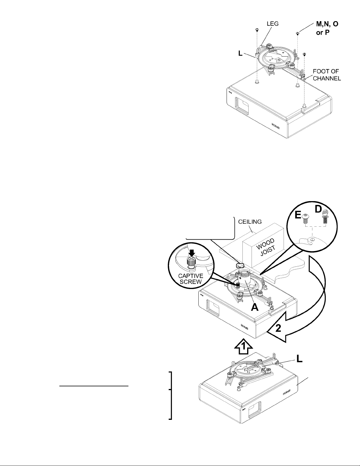
Attach adapter plate (L) to projector using one
screw (M, N, O or P) for each channel as shown.
Tighten all screws, while keeping the center ofgravity.
Be sure that adapter plate (L) is straight. Adjust the
feet ofthe channels to keep the adapter plate level.
Tighten all screws with 4 mm security allen wrench
(B) orwrench provided with projector mount, while
keeping the center of gravity. If M3 screws are used,
tighten using 2 mm security allen wrench (Q).
NOTE: Projectors may require different size screws
for mounting. Use a combination ofscrews (M, N, O
or P) and foot adjustment that will result in channels
of adapter plate (L) fitting tightly against projector.
Important: In order to properly engage the threads in
the mounting holes, the screw must be turned at least
3 full turns.
NOTE: If using screw (M), place washer (R) between
screw (M) and foot of channel.
Attaching Adapter Plate to Projector Mount
Attach projector, with adapter plate already on
O
it, to the projector mount (A) by inserting the
projector mount (A) into the adapter plate
connection and twisting until the adapter plate
will no longer turn (about 75°). The spring
loaded captive screw should line up with a
corresponding hole on the adapter plate (this
should line up automatically when the two are
connected). Push down and tighten the spring
loaded captive screw to secure the adapter
plate to the mount. If not using the optional
security feature, fasten thumb
screw (D) in the hole opposite the spring loaded
captive screw.
OPTIONAL: For security option, use #10-32 x
3/8" security screw (E) in the hole opposite
the spring loaded captive screw. Tighten with
security allen wrench (B). This will prevent the
projectorfrom being removed.
NOTE: Be sure to only use the #10-32 x 3/8"
screw (E) (or the thumb screw (D) opposite
the spring loaded captive screw.
CUTAWAY VIEW
OF CEILING
PLATE (G)
PROJECTOR
A WARNING
Do not lift more weight than you can handle! Use
additional man power or mechanical lifting equip
ment to safely handle placement ofthe projector!
Visit the Peerless Web Site atwww.peerlessmounts.com For Technical Support Contact Peerless Mounts at 1-800-729-0307 or708-865-8870.
8 of10
ISSUED:01-23-07 SHEET #:055-9498-4 05-20-10
Page 9

Projector Alignment
To adjust roll, pitch and yaw loosen the set screw
o
(shown below) using alien wrench (B). You should be
able tojust slightly loosen the screw so that your adjust
ments can be set without having to hold the projector.
Move projector to desired position and slowly tighten set
screw.
IMPORTANT: Allen wrench is your key for projector removal. Store it in a safe place.
PROJECTOR
NOTE: All accessories are available for purchase through Epson (www.epson.com)
ELPMBP01
Adjustable Suspended Ceiling
Channel Kit
• Adjustable carriage allows for ideal
projector positioning below a2'x2' or 2'
X 4' standard ceiling tile
• Pre-assembled, easy to install design
reduces installation time
• Knockouts are provided for electrical
outlet boxes and antenna leads
• Escutcheon ring leaves a clean finish
• Compact and lightweight
• Includes Kwik-LocTM self locking cable
joiners for simple cable support set-up
ELPMBP03
Structural Round Ceiling Plate
• Mounts to wood joist or structural concrete ceiling
• Features cable management access hole
• 1 %" -11.5" NPT fitting for attachment of
adjustable extension column
• Max weight load: 150 lb (68 kg.)
• Color: White
Accessories
ELPMBP02
False Ceiling Plate Kit
• Replaces a2'x2' ceiling tile and mounts to
structural ceiling with tie wires
• Two-piece design offers five different points
for mount attachment
• Includes tie wire supports and fiush mount
tube
• 1 -11.5" NPT fitting for attachment of
adjustable extension column
• Two knockout panels for electrical outlet
boxes
• Max weight load: 50 lb (23 kg.)
• Color: White
ELPMBC01
Adjustable Extension Column (Pipe)
8"- 11"
• 8"-11" adjustable extension in 1" increments
• Specially designed to allow internal cable
management
• 1 %" -11.5" NPT pipe threaded on both ends
• Notched ends for use with set screw to provide
safety and security
• Color: White
Uus
Visit the Peerless Web Site atwww.peerlessmounts.com For Technical Support Contact Peerless Mounts at 1-800-729-0307 or708-865-8870.
9 of10
ISSUED:01-23-07 SHEET #:055-9498-4 05-20-10
Page 10

LIMITED FIVE-YEAR WARRANTY
Peerless Industries, Inc. establishes a warranty period offive years for products manufactured or supplied by Peerless. This period commences from the date of
sale ofthe productto the original consumer, butwill in no case lastfor more than sixyears afterthe date ofthe product’s manufacture. During the warranty period
such products will be free from defects in material and workmanship, provided they are installed and used in compliance with the instructions established by
Peerless Industries, Inc. Subject to applicable legal requirements, during the warranty period Peerless will repair or replace, or refund the purchase price of, any
Any otherwarranties prescribed by the law which may apply with respect to such products also are limited in duration to the warranty period specified in this
This warranty does not cover damage caused by (a) service or repairs by the customer or a person who is not authorized for such service or repairs by Peerless
Industries, Inc., (b) the failure to utilize proper packing when returning the product, (c) incorrect installation or the failure to follow Peerless’ instructions or warnings
when installing, using or storing the product, or (d) misuse or accident, in transit or otherwise, including in cases ofthird party actions and force majeure.
In no event shall Peerless be liable for incidental or consequential damages or damages arising from the theft of any product, whether or not secured by a security
This Limited Five-Year Warranty is in lieu of all other warranties, expressed or implied, and is the sole remedy with respect to product defects. No retailer, dealer,
distributor, installer or other person is authorized to modify or extend this warranty or impose any obligation on Peerless in connection with the sale of any product
This warranty gives specific legal rights, and you may also have other rights provided bythe national legislation ofthe country in which you purchased such
such product which fails to conform with this warranty.
Limited Five-YearWarranty.
device which may be included with the product.
manufactured or supplied by Peerless.
product.
teerless*
www.peerlessmounts.com
© 2008 Peerless Industries, Inc.
Visit the Peerless Web Site atwww.peerlessmounts.com For Technical Support Contact Peerless Mounts at 1-800-729-0307 or708-865-8870.
10 oflO
All other brand and product names are trademarks or registered trademarks oftheir respective owners.
ISSUED:01-23-07 SHEET #:055-9498-4 05-20-10
© 2008 Peerless Industries, Inc. All rights reserved.
 Loading...