

Page 1
INSTALLATION MANUAL
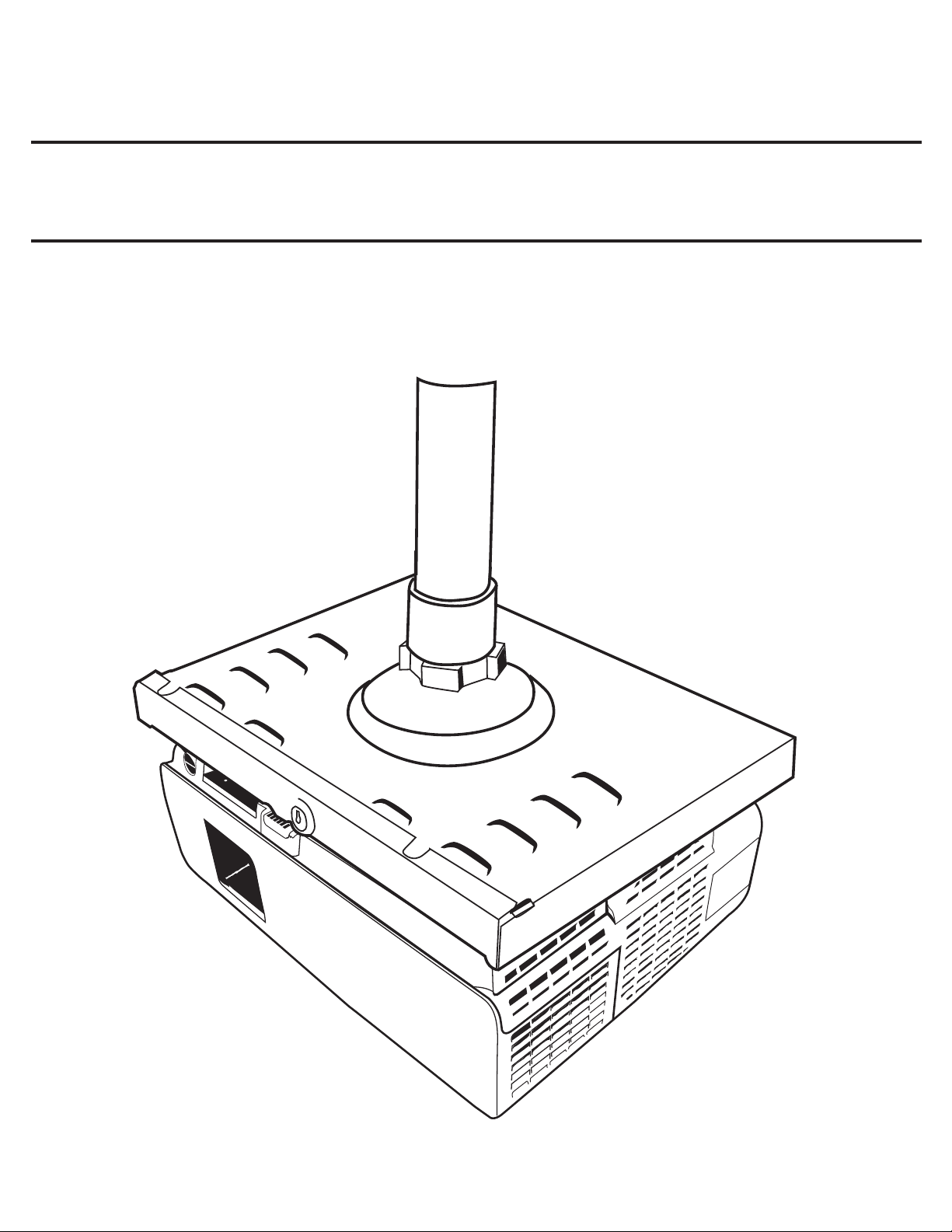
High Security Projector Ceiling Mount
MODEL# ELPMBATA
Manufactured by:
Business Machine Security, Inc.
520 W. Central Ave.
Brea, CA 92821
www.LocDown.com
Page 2

Table of Contents
Limited Warranty Information....................................................................................... 3
Contact Business Machine Security............................................................................. 3
Warning Statement........................................................................................................ 3
Parts List.........................................................................................................................4
Mount Assembly............................................................................................................. 5
Securing Receiver Tray to Pipe..................................................................................... 6
Mounting Projector to Grid Plate............................................................................ 7-9
Locking Grid Plate to Receiver Tray...........................................................................10
Adjusting Mount........................................................................................................... 11
INSTALLATION MANUAL
2
Page 3
Business Machine Security
Limited Warranty Information
Business Machine Security, Inc. warrants the original purchaser of Business Machine Security, Inc. products that they be free of defects in
material and workmanship for life from the date of purchase. User assumes all risk and liability resulting from the use of the products, whether
used singly or in combination with other goods. Business Machine Security, Inc. neither assumes nor authorizes any person to assume for it any
liability in connection with the sale or use of the products sold and there are no oral agreements or warranties collateral to or affecting this limited
warranty. Business Machine Security, Inc.’s only responsibility under this warranty is for the repair or replacement of any Business Machine
Security, Inc. product found to be defective during the warranty period. Business Machine Security, Inc. assumes no responsibility whatsoever
for special, indirect or consequential damages resulting from the use of Business Machine Security, Inc. products, and specically assumes no
liability for the loss or damage to equipment or data. The remedies set forth in this Limited Warranty are exclusive and the liability of Business
Machine Security, Inc. with respect to any contract of sale or anything done in connection therewith, whether in contract, in tort, under any
warranty or otherwise shall not, except as expressly provided herein, exceed the price of the equipment or part on which such liability is based.
Any damage caused by the improper use, operation beyond capacity, substitution of parts or equipment not approved by Business Machine
Security, Inc., improper packaging, failure to observe installation or other instructions, transit, or repair by one other than Business Machine
Security, Inc., will not be covered by and shall void this Limited Warranty.
THIS IS THE ONLY WARRANTY GIVEN, AND EXCLUDES ALL OTHER WARRANTIES, INCLUDING ANY WARRANTY
OF MERCHANTABILITY OR FITNESS FOR A PARTICULAR PURPOSE.
Contact Business Machine Security
Customer Service/ Technical Support at (800) 872-9562 or customerservice@locdown.com
Important Warnings and Cautions!
Warning Failure to read, understand, and follow instructions can result in serious personal injury, damage to equipment, or voiding
Warning Improper installation can result in serious personal injury or death. The mounting surface must support a weight factor of
Warning It is the installer’s responsibility to make sure the mounting surface can support the combined weight of the mount and
Warning It is the installer’s responsibility to make sure that mounting surface and subsurface is free and clear of all electrical wires,
Warning Mount and equipment exceeding a combined weight of 60 lbs. can result in damage to the support structure, the mount, the
Warning Business Machine Security, Inc. does not warrant its mounts against damage caused by the use of its mounts for any purpose
Warning Proper safety gear and practices should be adhered to at all times throughout the installation process.
equipment warranty.
four times the combined total weight of the equipment and the mount. If not, reinforcement of the mounting surface will be
necessary before installing the mount.
equipment by a factor of four times.
plumbing and gas pipes. Failure to provide adequate clearance of all electrical wires and pipes can result in re, serious
personal injury or death.
equipment, and may cause serious personal injury.
other than for the purposes for which it has been designed. Business Machine Security, Inc. is not responsible for damage, or
injury that may result in the use of any unauthorized modications or attachment.
Warning Do not install the mount near any heat source or air conditioning vent which may be prone to vibration.
Warning Maximum load capacity of mount: 25 lb
Warning When installing or adjusting the ceiling mount, do not use adhesives, lubricants, or oils to prevent the screws from loosening.
If you use adhesives, lubricants, or oils to prevent the screws from loosening, the casing may crack and the projector may fall,
causing serious injury and damage to the projector.
INSTALLATION MANUAL
3
Page 4
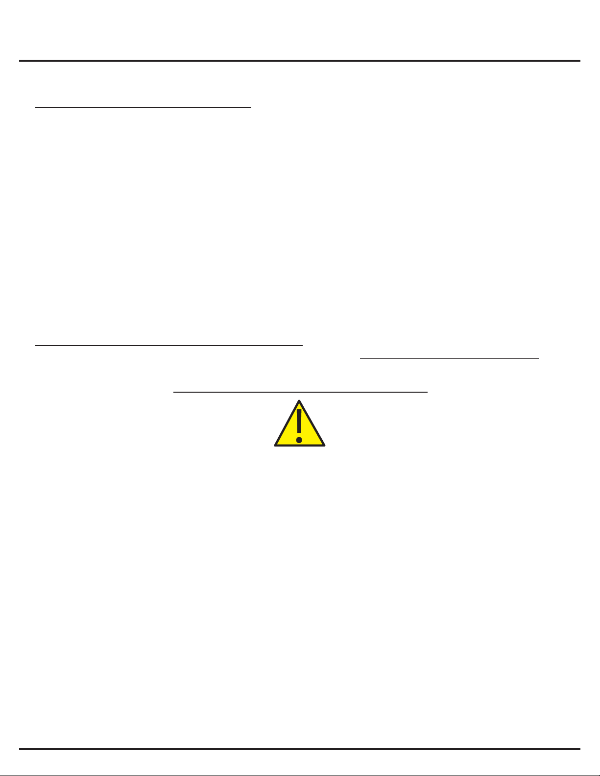
Installation Tools
Phillips Head Screwdriver
(not provided)
Parts List
Mounting Hardware
4mm X 10mm
Pan Head Metric Screw
(Qty 4)
4mm X 20mm
Pan Head Metric Screw
(Qty 4)
Pipe Adhesive
(provided)
#10 SAE Flat Washer
(Qty 4)
3/8” Thick
Spacer
(Qty 4)
INSTALLATION MANUAL
4
Page 5

Mount Assembly
PARTS LEGEND
A 1-1/2” Threaded Pipe (Not provided)
B Pipe Adhesive
C 1-1/2” Pipe Coupler
D Tensioning Ring
E Receiver Tray
F Grid Plate
G Pan Head Metric Screw*
4mm X 10mm
4mm X 20mm
H #10 SAE Flat Washer
I Screw Lock
J 3/8” Spacer
P Projector (Not included)
*see pages 7-9 for proper
hardware to use for your
model projector
GRID PLATE TO RECEIVER TRAY
INSTALLATION MANUAL
5
Page 6

Securing Receiver Tray to Pipe
Twist off the cap from the Pipe Thread Adhesive tube (B). Cut off the tip. Apply it to the inside of the
coupler (C) at the top, for about 1/4” or approximately three threads. Screw the coupler (C) clockwise
(as viewed from below), with the Receiver Tray (E) already assembled, onto the pre-installed 1-1/2”
standard pipe threads (A). This connection should be as tight and stable as possible.
WARNING: It is the installers responsibility to be sure that the structure to which this mount will be attached, can
support four times the combined weight of the equipment, mount and supporting hardware.
(not provided)
INSTALLATION MANUAL
6
Page 7

Mounting Projector to Grid Plate
1. Turn the projector (P) upside down and place it at on a soft cloth or packaging material. Remove
or adjust the feet to be as ush as possible to the projector bottom.
2. Place the Grid Plate (F) on the bottom of the projector and line it up so the mounting inserts of
the projector (P) can be seen through the holes of the Grid Plate (F). (NOTE: see pages 8-9 for which
mounting holes to use for your model projector)
3. Select the screws (G) for your projector (see pages 8-9 for proper hardware to use for your model
projector)
4. Attach the Grid Plate (F) to the projector using these screws (G) and washers (H). Turn until snug.
Do not over tighten.
Soft Cloth or
Packaging Material
NOTE: The 400W need 3/8” Spacers
(J) to level the Grid Plate (F). Place the
Spacers (J) over the mounting inserts
and then place the Grid Plate (F) on
top of the Spacers (J) lining up the
proper holes of the Grid Plate (F) with
the projector’s (P) mounting inserts.
INSTALLATION MANUAL
7
Page 8
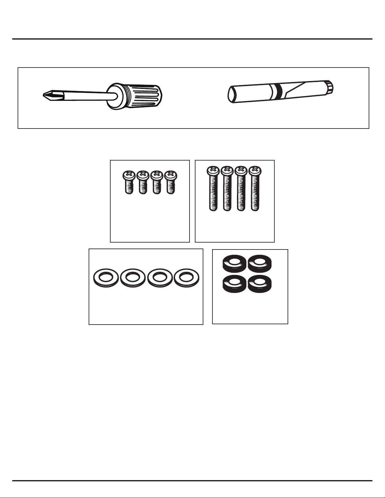
Epson Projector Model#
1700c, 1705c, 1710c, 1715c
Mounting Inserts
Grid Plate Alignment
HARDWARE
Mounting Inserts:
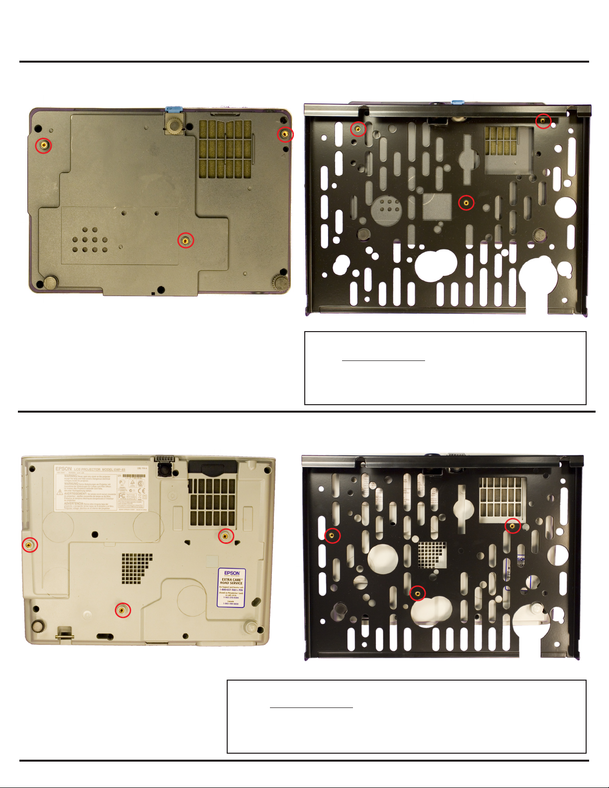
Epson Projector Model#
S5, 77c, 83+, 822+, 400W
• #10 SAE Flat Washers (Qty 3)
• 4mm X 10mm Pan Head Metric Screws (Qty 3)
Mounting Inserts
Grid Plate Alignment
INSTALLATION MANUAL
HARDWARE
Mounting Inserts:
• #10 SAE Flat Washers (Qty 3)
• 4mm X 10mm Pan Head Metric Screws (Qty 3)
• 4mm X 20mm Pan Head Metric Screws (Qty 3) (400W model only)
• 3/8 Spacers (Qty 3) (400w model only)
8
Page 9

Epson Projector Model#
6110i
NOTE: For updated information on
compatibility with the latest Epson
projector models, visit www.epson.com”
Mounting Inserts
Grid Plate Alignment
HARDWARE
Mounting Inserts:
• #10 SAE Flat Washers (Qty 4)
• 4mm X 10mm Pan Head Metric Screws (Qty 4)
INSTALLATION MANUAL
9
Page 10

Locking Grid Plate to Receiver Tray
1. After the Receiver Tray (E) has been attached to the ceiling and the projector has been attached
to the Grid Plate (F), slide the Grid Plate (F) into the Receiver Tray (E).
Before completely closing the mount, route the cables that are running down the 1-1/2” Pipe (A)
and out the center of the Receiver Tray (E). (See gure 6)
Slide the Grid Plate (F) in while guiding the cables into a slot located in the back of the Grid Plate
(F). (See gure 7)
2. Put the Screw Lock (I) into the Grid Plate (F) and turn clockwise until it is snug.
WARNING: DO NOT OVER TIGHTEN THE LOCK.
gure 6
INSTALLATION MANUAL
CABLE SLOT
gure 7
10
Page 11

Adjusting Mount
1. To align the projector, simply grab a hold of either side of the mount and gently adjust by lifting
up and pushing down until you have the proper registration. If you wish to add or lessen the
tension, turn the Tension Ring until the desired amount has been achieved. The Tension Ring can
be turned to lock in the registration once the installation is complete.
TENSION RING
Loosen to Adjust
Tighten to Lock
INSTALLATION MANUAL
Gently Adjust
All other brand and product names are trademarks or registered trademarks of their respected owners.
11
 Loading...