

Page 1
Installation Guide
Page 2

About this Guide
About the Explanations in this Guide
•
This guide provides explanations for the following procedures.
•
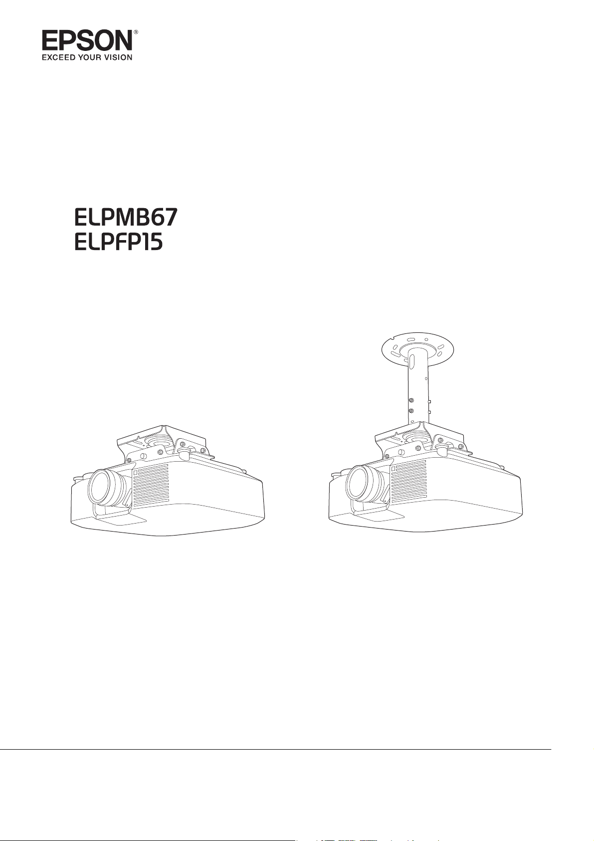
Installing the projector using the Ceiling Mount (ELPMB67)
•
Installing the projector using a combination of the Ceiling Mount (ELPMB67) and Suspension Adapter (ELPFP15)
•
Illustrations of the projector used in this guide may differ from the projector you are using.
1
Page 3

Contents
About this Guide
About the Explanations in this Guide . . . 1
Introduction
Using the Product Safely ............... 3
Safety Indications .......................3
General Information Indications .............3
Notes on Installation ..................... 3
Notes on the Installation Location ............ 5
Package Contents .......................6
ELPMB67 ............................ 6
ELPFP15 ............................ 7
Specifications . . . . . ................... 9
ELPMB67 .............................. 9
ELPFP15 ..............................9
Installation Method
Preparation ......................... 11
Checking the Installation Location ........... 11
Attaching the projector mount to the projector
.................................... 11
Attaching the projector mount ...........11
Preparing the Suspension Adapter (when Using
ELPFP15) .............................11
Installing on a Ceiling or a Wall ........ 14
Securing the Ceiling Plate/Ceiling Mount Pipe
to the Installation Surface .................14
When installing on a concrete surface ......14
When attaching to an aluminum truss
(ELPMB67 only) ......................15
Attaching the projector mount to the ceiling
plate ................................ 16
Adjusting the position of the image ..........17
Adjusting the vertical position of the image
.................................. 17
Adjusting the angle of the image.........19
Adjusting the size of the image ........... 19
Installing the safety wire .................. 20
Connecting the Ceiling Mount to the ceiling
with a wire ......................... 20
Connecting the Ceiling Mount to the
projector with a wire .................. 22
2
Page 4
Introduction
Using the Product Safely
For your safety, read all the instructions in this guide before using this product. Incomplete or incorrect
installation could cause damage to the product or result in personal injury or property damage. Keep this
installation manual at hand for later reference.
Read the User's Guide and Safety Instructions for your projector and follow the instructions in these documents.
Safety Indications
The documentation and this product use graphical symbols to show how to use this product safely.
The indications and their meaning are as follows. Make sure you understand them properly before reading
the guide.
Symbol Explanation
Warning
Caution
This symbol indicates information that, if ignored, could possibly result in serious injury or
even death due to incorrect handling.
This symbol indicates information that, if ignored, could possibly result in personal injury or
physical damage due to incorrect handling.
General Information Indications
Symbol Explanation
Symbol indicating an action that must not be done
Symbol indicating an action that should be done
Symbol indicating related or useful information
c
Notes on Installation
Warning
This product is for projectors. If anything other than a projector is mounted, the weight
may result in damage.
If this product or projector falls, it could cause death or personal injury.
Installation should be performed by a qualified technician with the necessary skills and
knowhow.
Incomplete or incorrect installation could cause the product or projector to fall and cause personal
injury or an accident.
Do not attach anything other than an Epson projector to this product.
Doing so could cause the mount to fall or break and cause personal injury or an accident.
Follow the steps in this guide to install the product, and be sure to use the bolts and screws
specified in this guide.
If the instructions are not followed, this product may fall, resulting in personal injury or an accident.
3
Page 5
Introduction
Warning
Handle the power cord carefully to avoid fire or electric shock.
Incorrect handling could cause fire or electric shock. Observe the following precautions when
handling:
•
Do not handle the power plug with wet hands.
•
Do not use a power cord that is damaged or modified.
•
Do not pull the power cord with too much force when routing the cable through the setting plate.
Do not install the product in a location where it might be exposed to vibration or shock,
which could cause damage to the projector or mounting surface.
This could cause damage to the projector or mounting surface. If this product falls, it could cause
death or personal injury.
The installation work should be performed by at least two qualified service personnel. If
you need to loosen any screws while installing, be careful not to drop the mount.
If this product falls, it could cause death or personal injury.
The installation surface requires enough strength to hold the projector and this product.
Before installing, check the total mass of the projector and this product to ensure that the installation surface is strong enough to support the weight. If the wall is not strong enough, reinforce
the wall before installation.
Do not hang on the mount or hang a heavy object on it. Or do not hang a heavy object on
the mount.
If this product falls, it could cause death or personal injury.
Do not use adhesives, lubricants, or oils to install or adjust the product.
If you use adhesives to prevent the screws from loosening or things such as lubricants or oils on
the slide plate fixing part of the projector, the case may crack and cause the projector to fall,
resulting in personal injury or property damage.
Tighten all screws firmly after adjustment.
Otherwise, the projector or mount may fall and cause personal injury or property damage.
Never loosen the screws after installation.
Confirm on a regular basis that the screws have not become loose. If you find any loose screws,
tighten them firmly. Otherwise, the projector or mount may fall and cause personal injury or property damage.
Attach the safety wire supplied to prevent the product from falling due to earthquakes or
vibrations.
Inspect the product on a regular basis to ensure there is no damage.
If any parts are damaged, stop using the setting plate immediately. If this product falls, it could
cause death or personal injury.
Do not use the projector in a location subject to combustible or explosive gas.
High temperatures within the projector may cause ignition and a fire to occur.
Only a specialist should remove or reinstall the projector, including for maintenance and
repairs.
See the projector's User's Guide for instructions on maintenance and repairs.
4
Page 6
Introduction
Caution
Do not disassemble or remodel this product.
Install the product in a location free from humidity and dust to prevent the projector's lens
and optical components from becoming dirty.
Do not use excessive force when adjusting this product.
This product may break, resulting in personal injury.
Notes on the Installation Location
Warning
Do not install in a location subject to oily smoke or smoke for events.
If oils and so on stick to the slide plate fixing part of the projector, the case may crack and cause
the projector to fall, resulting in personal injury or property damage.
Caution
Do not install the product in a location where the operating temperature of the projector
might be exceeded.
Otherwise, damage may result. See the User's Guide supplied with the projector for the operating
temperature range.
Make sure there is enough space around the projector.
See the User's Guide supplied with the projector for the necessary space required.
Install the projector at a place away from other electric devices such as fluorescent lights
or air conditioning.
Some types of fluorescent lights could interfere with the remote control.
5
Page 7
Introduction
Package Contents
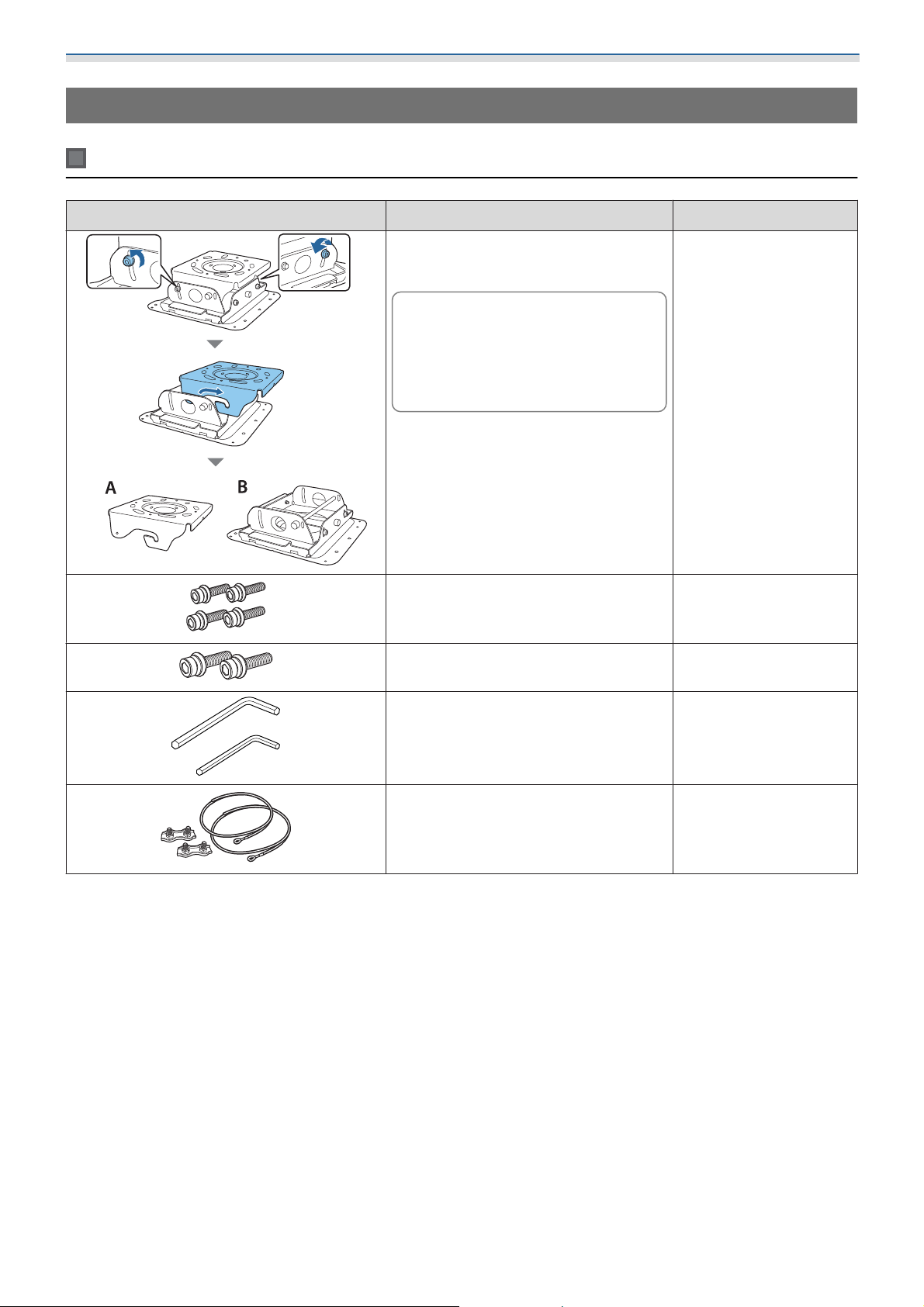
ELPMB67
Part Name Application
A: Ceiling plate
B: Projector mount
Temporarily assembled at
c
M6 x 15 mm hexagon socket head cap
bolts with washers (x4)
M8 x 16 mm hexagon socket head cap
bolts (x2)
the time of purchase. See
the illustration on the left to
separate the parts before
installing.
-
Used to attach the projector mount to the projector.
Used to attach the projector to a wall.
Hexagonal wrenches (1 for M6 and 1 for
M8)
Safety wire set (for ceiling installation)
•
Safety wires (x2)
•
Wire clips (x2)
-
Used to connect the
product to the installation surface to prevent
the product from falling.
6
Page 8
Introduction
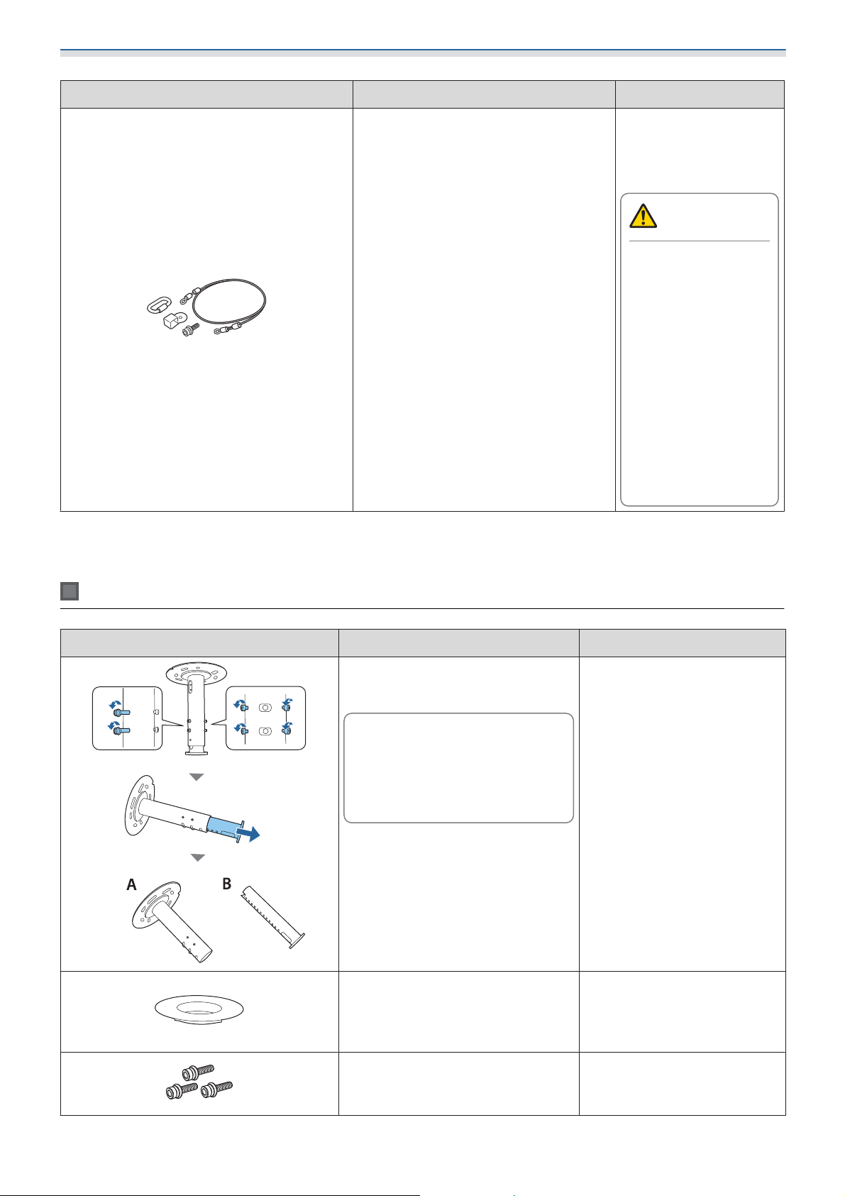
Part Name Application
Safety wire set (for projector installation)
•
Safety wire (x1)
•
Carabiner (x1)
•
Wire ring (x1)
•
M6 x 15 mm bolt (x1)
•
Use only the supplied bolts to install the mount. Do not substitute these bolts with any other types.
•
Gather the tools and parts you need before you begin installation.
Connect this product to
the projector to prevent
the projector from falling.
Do not attach the
wire ring to a projector that does not
have a dedicated
wire ring attachment
section.
Attaching it to a location other than the
wire ring attachment
section may cause
the projector to fall
and cause personal
injury or an accident.
Warning
ELPFP15
Part Name Application
A: Ceiling mount pipe
B: Adjustment pipe
Temporarily assembled
c
Veneer plate Install this to make the gap be-
at the time of purchase.
See the illustration on
the left to separate the
parts before installing.
-
tween the hole in the installation surface and the Suspension Adapter less noticeable.
M6 x 16 mm hexagon socket head
cap bolts
with washers (x3)
7
Used to attach the adjustment
pipe to the ceiling plate for the
ELPMB67.
Page 9

Introduction
Part Name Application
•
Use only the supplied bolts to install the mount.
•
Gather the tools you need.
Safety wire set (for ceiling installation)
•
Safety wire (x2)
•
Wire clips (x2)
Used to connect the product
to the installation surface to
prevent the product from falling.
8
Page 10
Introduction
Specifications
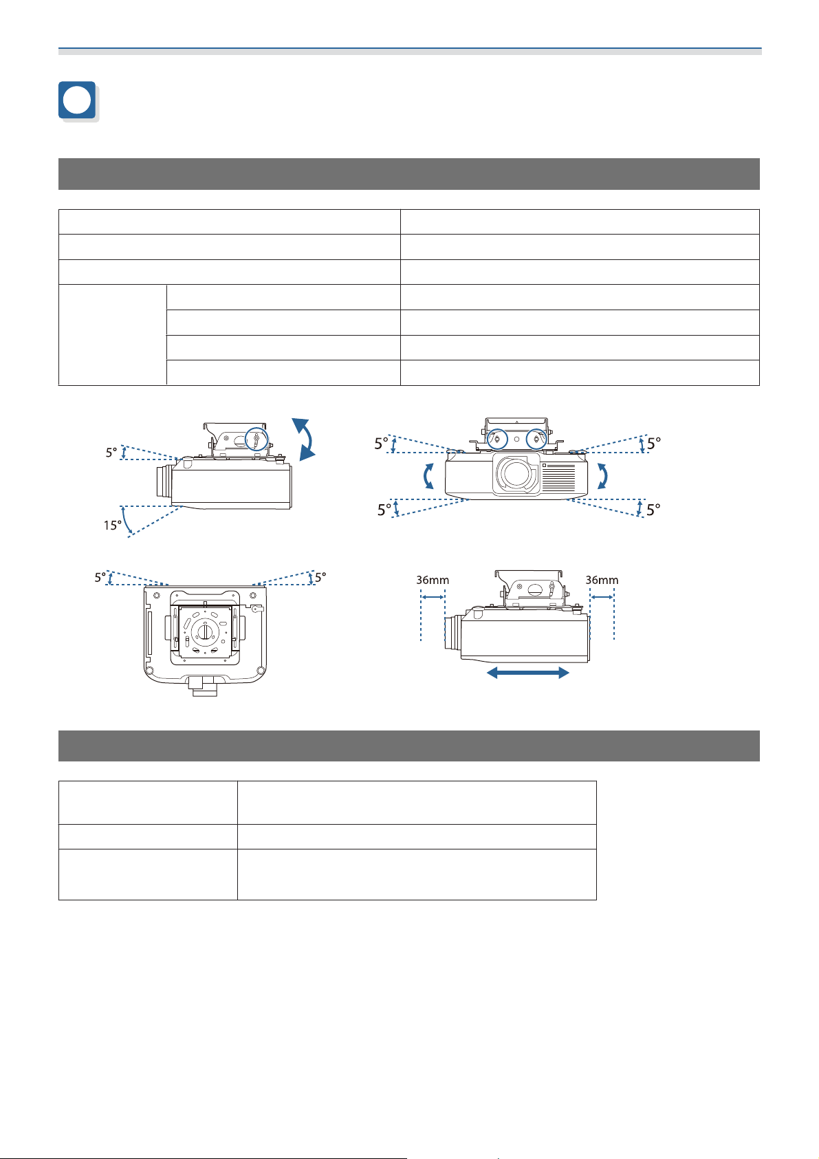
ELPMB67
External dimensions when assembled 330 × 124 × 356 mm
Mass Approx. 5.7 kg
Load-bearing capacity 40 kg
Adjustment
range
Vertical tilt angle -15 to 5°
Horizontal tilt angle ±5°
Horizontal rotation angle ±5°
Front/back slide ±36 mm
Vertical tilt angle Horizontal tilt angle
Horizontal rotation angle Front/back slide
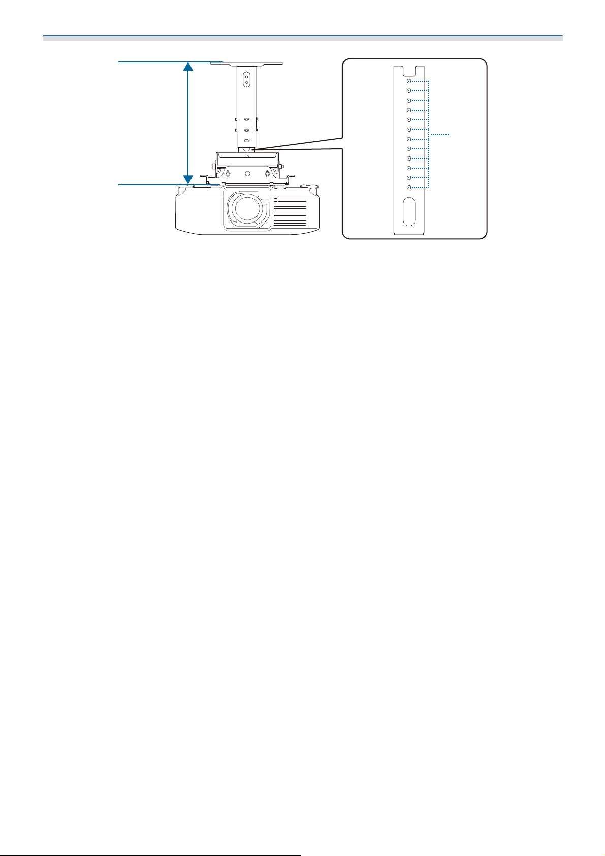
ELPFP15
External dimensions when
assembled
Mass Approx. 4.4 kg
Adjustment range 460 to 680 mm
Φ270 × 352 mm
(Distance between adjustment holes: 20 mm)
9
Page 11
Introduction
460〜680mm
20mm
10
Page 12
Installation Method
Preparation
Checking the Installation Location
Before installing, check the projection distance to the screen and make sure the projector is in the correct
position.
The projection distance to the screen varies depending on the projector. See the User's Guide supplied with
the projector you are using.
Attaching the projector mount to the projector
Attaching the projector mount
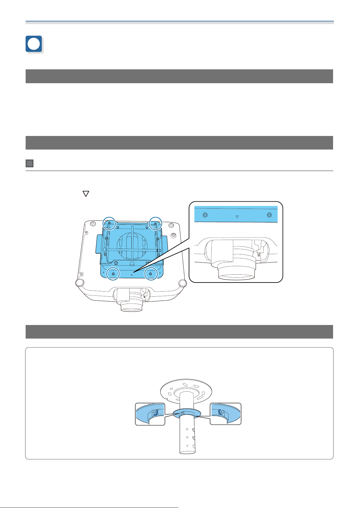
Attach the projector mount to the bottom of the projector using the supplied M6 x 15 mm bolts (x4).
Make sure that the
mark on the projector mount is facing the lens side of the projector.
Preparing the Suspension Adapter (when Using ELPFP15)
When using the veneer plate supplied, pass the plate over the ceiling mount pipe in advance.
Attaching the veneer plate makes the gap between the installation surface and the Suspension
c
Adapter less noticeable.
11
Page 13
Installation Method
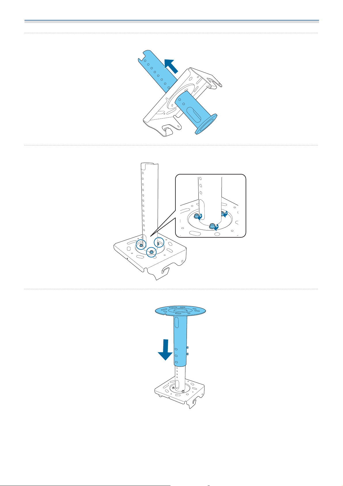
Insert the adjustment pipe into the ceiling plate for the ELPMB67
a
Secure with the M6 x 16 mm bolts (x3) supplied
b
c
Insert the ceiling mount pipe into the adjustment pipe
12
Page 14
Installation Method
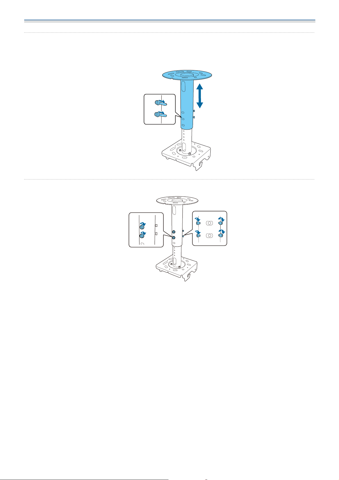
Adjust the position so that it reaches the required length, and then insert the fixing bolts
d
(x2) that were removed beforehand
The holes for height adjustment are 20 mm apart.
e
Tighten all of the fixing bolts (6 points) to secure it in place
13
Page 15
Installation Method
Installing on a Ceiling or a Wall
Securing the Ceiling Plate/Ceiling Mount Pipe to the Installation Surface
When installing on a concrete surface
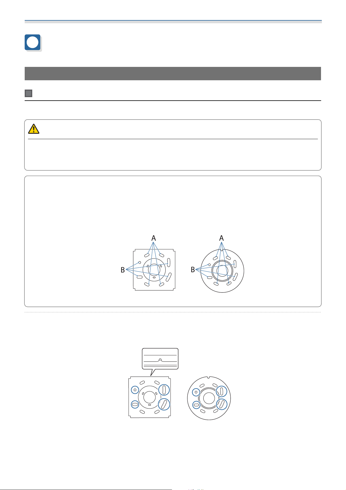
When installing on a concrete surface, you need 4 commercially available M12 anchor bolts.
Warning
•
Make sure that the installation surface (ceiling or wall) is strong enough to support the weight and horizontal
roll of the product and the projector.
•
If the installation surface is not strong enough, reinforce it before installation.
c
a
If you install this product after removing a mount that had already been installed, such as the
ELPMB47/ELPMB48/ELPMB22, you can use the mounting holes in the ceiling as they are.
The holes to be used depend on the mount being replaced. See the following illustration for more
details.
•
When replacing from the ELPMB22: Use the holes indicated by A.
•
When replacing from the ELPMB47/ELPMB48: Use the holes indicated by B.
ELPMB67 ELPMB67+ELPFP15
Drill holes in the ceiling or wall where the product will be installed
The holes for securing the mount are shown in the following illustration. The notch in the mount is on
the lens side of the projector.
ELPMB67 ELPMB67+ELPFP15
14
Page 16
Installation Method
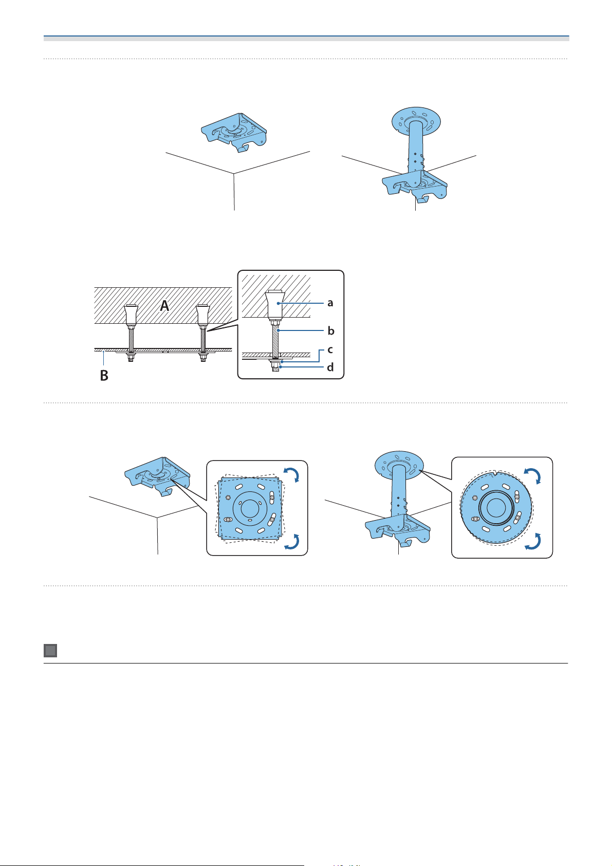
Use commercially available anchor bolts to temporarily secure the ceiling plate or the
b
ceiling mount pipe to the ceiling or wall
See the following illustration and install the product appropriately according to the conditions of the
installation surface.
ELPMB67 ELPMB67+ELPFP15
Concrete
A:
Ceiling/wall surface
B:
Female thread type anchor
a:
Hanging bolt
b:
Flat washer/spring washer
c:
Hexagon nut
d:
Adjust the position of the ceiling plate or the ceiling mount pipe to match the projection
c
d
When attaching to an aluminum truss, use at least two commercially available clamps to secure it in place.
The attachment method depends on the clamps you are using.
position
ELPMB67 ELPMB67+ELPFP15
When adjustment is complete, tighten the nut to completely secure the ceiling plate or the
ceiling mount pipe
When attaching to an aluminum truss (ELPMB67 only)
15
Page 17
Installation Method
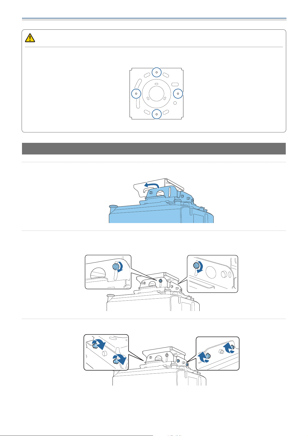
Caution
•
When attaching the clamps, be sure to use the nuts to secure them in place.
•
Secure at least two of the following screw holes for clamping so that they are symmetrical.
•
If you are using the ELPFP15, it cannot be secured with clamps.
Attaching the projector mount to the ceiling plate
a
b
Align the shaft of the projector mount with the slot in the ceiling plate, and insert it
Use the first 2 bolts that you removed to secure the 2 points shown in the following
illustration
c
Tighten the following bolts (4 points) to secure it in place
16
Page 18
Installation Method
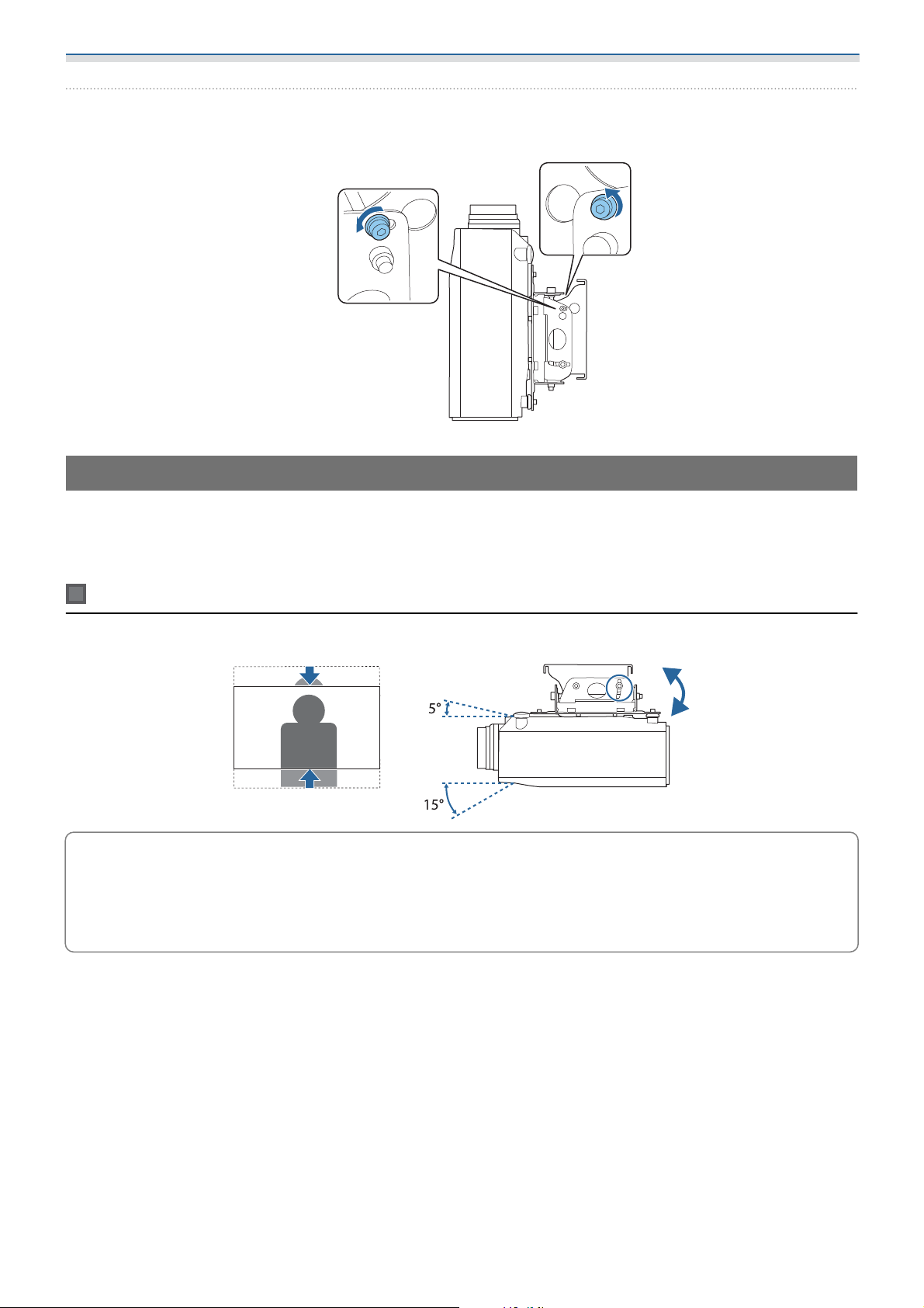
Only when mounting on a wall, use the two M8 x 16 mm bolts supplied to secure the
d
projector in place
Adjusting the position of the image
Project an image and adjust the position.
Connect the power cable to the projector in advance and turn it on.
Adjusting the vertical position of the image
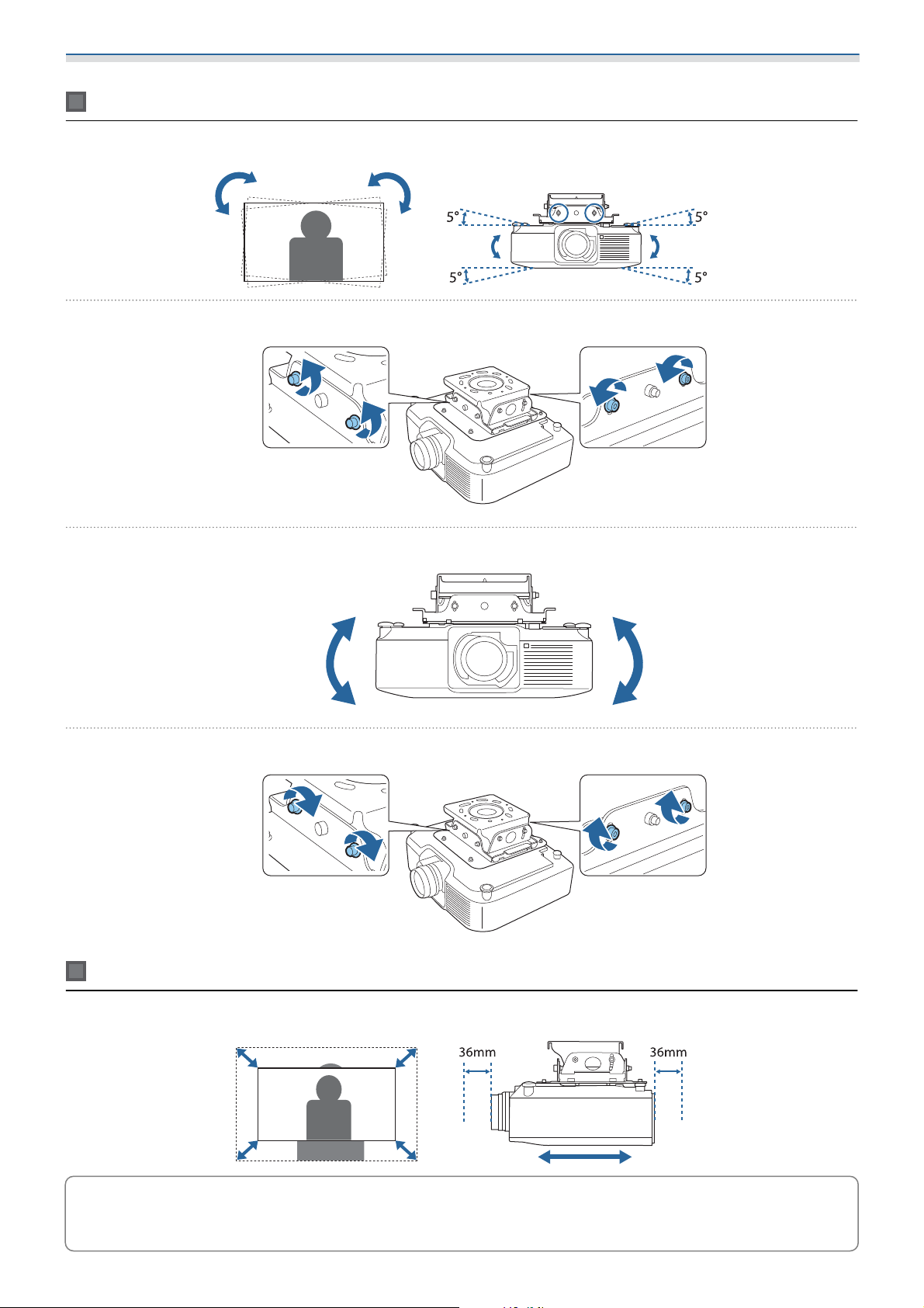
You can tilt the projector to adjust the vertical position of the image.
•
You can also adjust the vertical position of the image by using the projector’s lens shift function. See
c
the User's Guide supplied with the projector you are using for details on making adjustments.
•
If you are concerned about image distortion caused by tilting the projector, you can use the projector's
image correction functions to correct the image. See the User's Guide supplied with the projector you
are using for more details.
17
Page 19
Installation Method
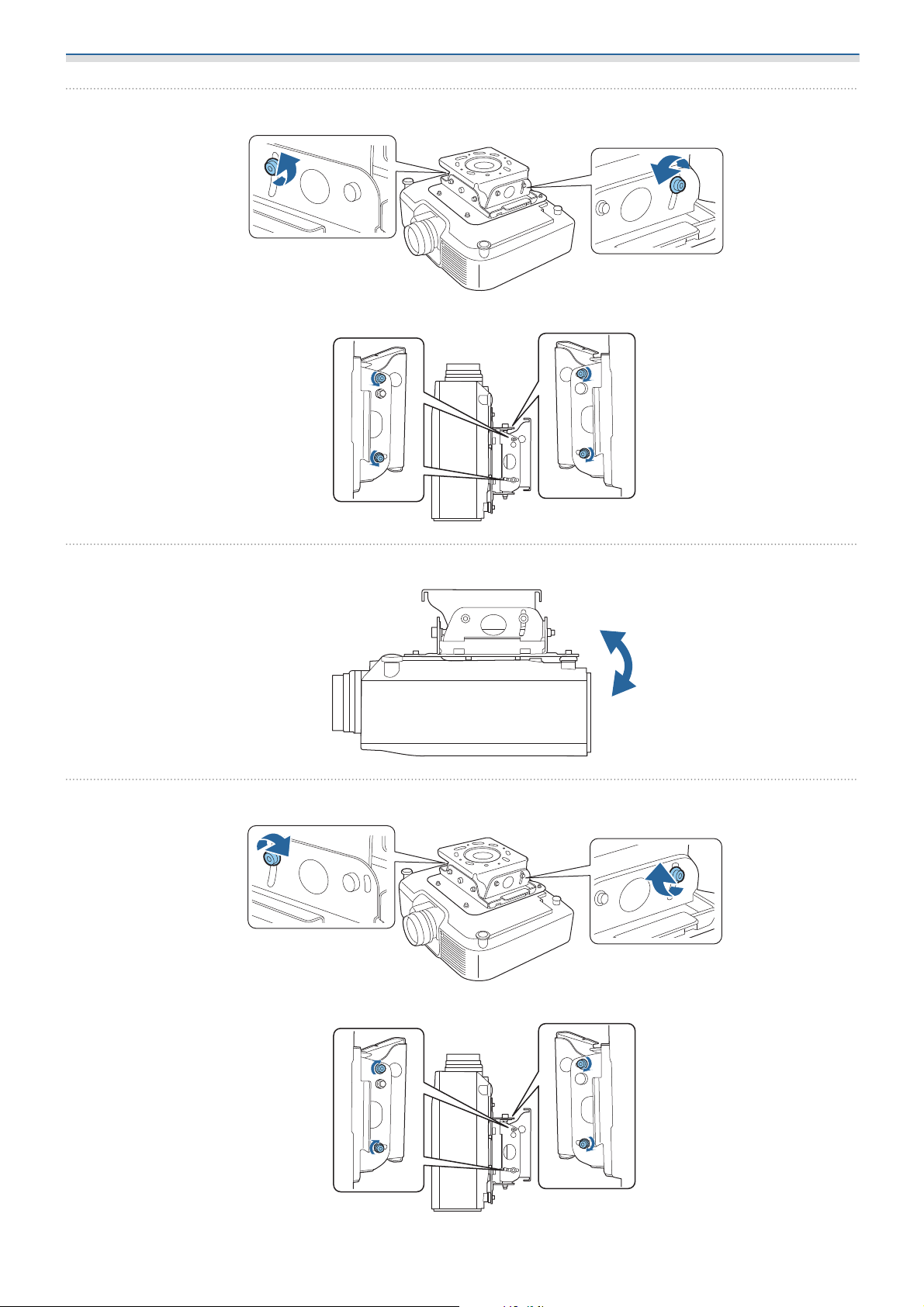
Loosen the bolts (2 points) shown below using the M8 wrench supplied
a
When installing the projector on a wall, loosen the bolts (4 points) shown below.
b
c
Raise and lower the back side of the projector to adjust the position of the image
When you have finished adjusting, re-tighten the loosened bolts (2 points)
When installing the projector on a wall, re-tighten the bolts (4 points) shown below.
18
Page 20
Installation Method
Adjusting the angle of the image
You can tilt the projector to adjust the angle of the image.
Loosen the bolts (4 points) shown below using the M8 wrench supplied
a
Tilt the projector to the left or right to adjust the angle of the image
b
When you have finished adjusting, re-tighten the loosened bolts (4 points)
c
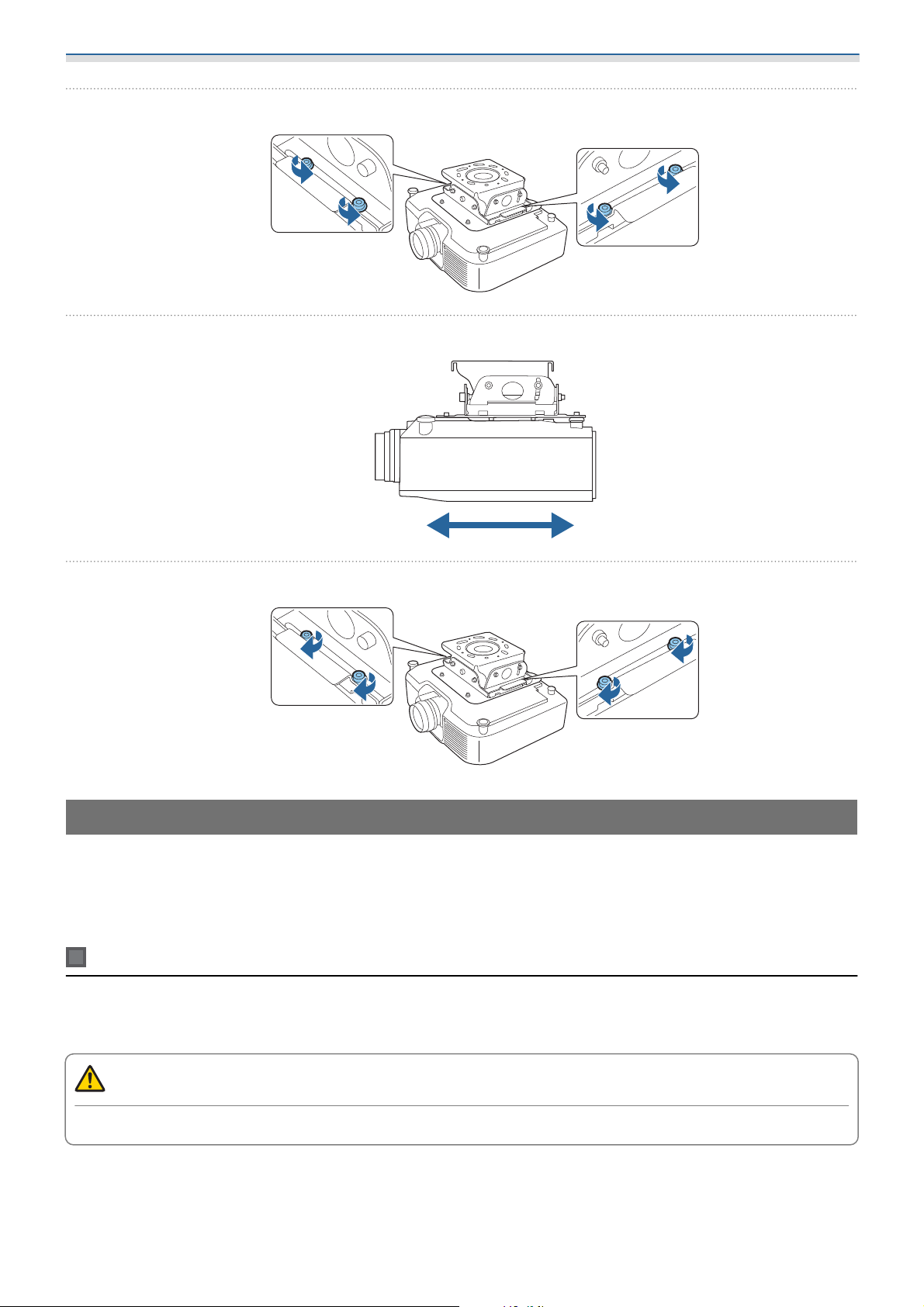
Adjusting the size of the image
You can adjust the size of the image by adjusting the front-to-back position of the projector
You can also adjust the size of the image by using the projector’s functions See the User's Guide
supplied with the projector you are using for details on making adjustments.
c
19
Page 21
Installation Method
Loosen the bolts (2 points) shown below using the M8 wrench supplied
a
Adjust the size of the image by sliding the projector back and forth
b
When you have finished adjusting, re-tighten the loosened bolts (2 points)
c
Installing the safety wire
To prevent the projector from falling, attach the safety wires (x2) supplied after installation.
If the safety wire supplied is too short, prepare a commercially available wire (a wire with a diameter of 1.5
mm or more).
Connecting the Ceiling Mount to the ceiling with a wire
Use the safety wire set (for ceiling installation) supplied.
Prepare commercially available anchor bolts to secure the end of the wire to the installation surface.
Caution
Check the safety wire in advance to make sure it is not damaged or frayed.
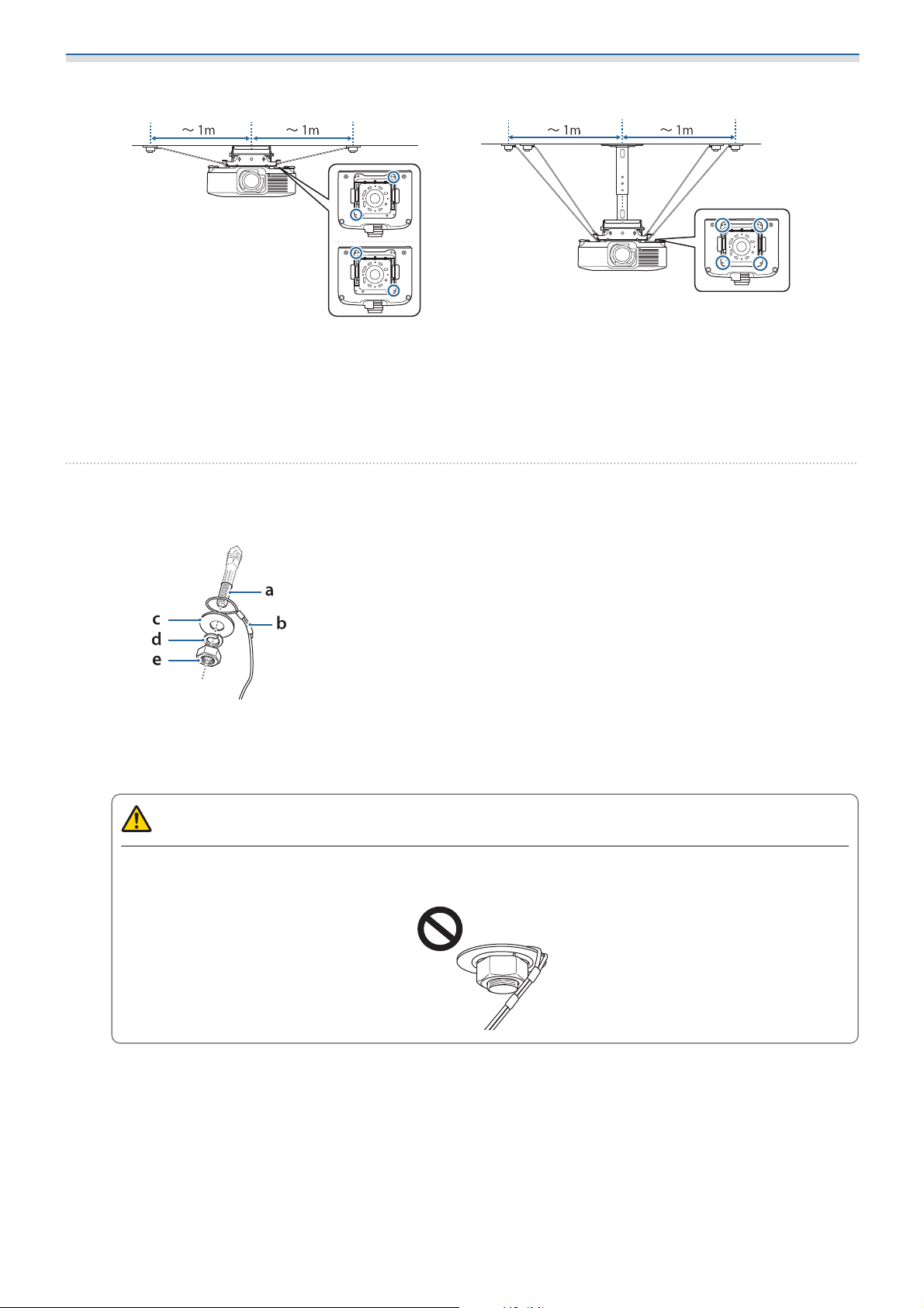
Checking the installation position
See the following illustration to check the wire attachment positions.
20
Page 22
Installation Method
ELPMB67
•
We recommend installing the anchor bolts on the ceiling within 1 meter from the center of this product.
•
If you are only using the ELPMB67, install the 2 wires diagonally.
•
If you are using the ELPMB67 in combination with the ELPFP15, install the 4 wires.
ELPMB67+ELPFP15
Installing
Secure the end of the safety wire (the end with a loop) to the ceiling using a commercially
a
available anchor bolt (M12)
a:
b:
c:
d:
e:
Hold the wire with the flat washer and the spring washer, and tighten the hexagon nut to secure it in
place.
Make sure that the loop on the safety wire does not protrude beyond the flat washer.
Anchor bolt
Safety wire
Flat washer (diameter 24 to 26 mm)
Spring washer
Hexagon nut
Caution
Make sure that the loop on the safety wire is not bent at a sharp angle. This could cause damage to
the wire.
21
Page 23
Installation Method
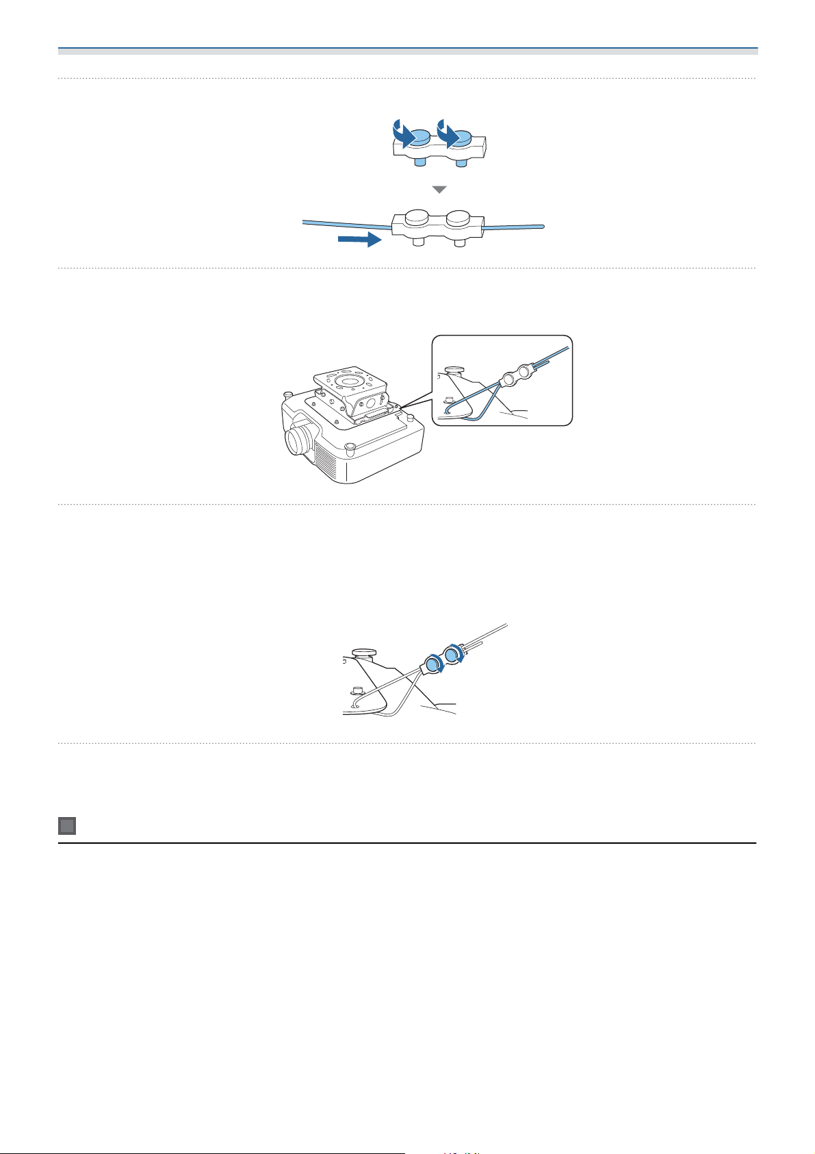
Loosen the screws on the wire clip and thread the safety wire through
b
Thread the safety wire through the hole in the projector mount
c
d
Make sure the end of the safety wire is threaded through the wire clip.
Adjust the length of the safety wire and tighten the screws on the wire clip to secure it in
place
Make sure the safety wire is as taut as possible.
If the end of the safety wire is too long, trim it to the appropriate length.
Follow steps 1 to 4 to attach the rest of the safety wires
e
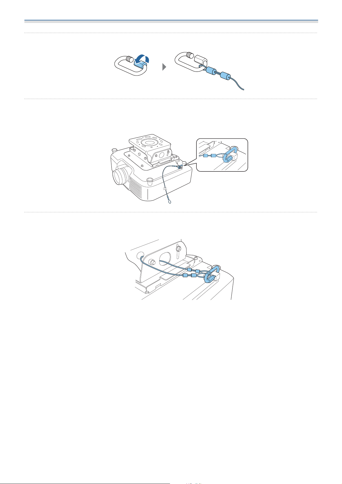
Connecting the Ceiling Mount to the projector with a wire
Use the safety wire set (for projector installation) supplied.
Installing
The points through which the safety wire is threaded vary depending on the projector. See the User's Guide
for the projector you are using.
The illustrations in the following procedure are an example only.
22
Page 24
Installation Method
Thread the carabiner through the end of the safety wire
a
Thread the carabiner through the projector’s wire ring
b
c
If you are using a projector that does not have a dedicated wire ring attachment section, thread it
through the safety wire attachment section.
Thread the safety wire through the projector mount and ceiling plate, and then tighten the
carabiner
23
© 2021 Seiko Epson Corporation
2021.4 Rev.1.0 (414137700)
 Loading...