

Page 1
Installation Guide
Guide d’installation
Guía de instalación
EnglishFrançaisEspañol
Page 2

Page 3
Using the Product Safely
Safety Instructions
For your safety, read all the instructions in this guide before using this product. Incorrect handling that ignores
instructions in this guide could damage this product or could result in personal injury or property damage.
Keep this installation guide at hand for future reference.
Read the User's Guide and Safety Instructions for your projector and follow the instructions in these documents.
Safety indications
The documentation and this product use graphical symbols to show how to use this product safely.
The indications and their meaning are as follows. Make sure you understand them properly before reading
the guide.
Symbol Explanation
Warning
Caution
This symbol indicates information that, if ignored, could possibly result in personal injury or
even death due to incorrect handling.
This symbol indicates information that, if ignored, could possibly result in personal injury or
physical damage due to incorrect handling.
Explanation of Symbols
Symbols Explanation
Symbol indicating an action that must not be done
Symbol indicating an action that should be done
Symbol indicating related or useful information
c
Safety Precautions for Installation
Warning
The setting plate is exclusively for mounting the projector on a wall. If anything other than
a projector is mounted, the weight may result in damage.
If this product falls, it could cause death or personal injury.
The installation work (wall mounting) should be performed by specialists who have tech‐
nical knowledge and ability. Incomplete or incorrect installation could cause the product
to fall and cause personal injury or property damage.
Follow the instructions in this guide when installing this product.
If the instructions are not followed, this product may fall, resulting in personal injury or an accident.
1
Page 4
Using the Product Safely
Warning
Handle the power cord carefully.
Incorrect handling may cause fire or electric shock. Observe the following precautions when han‐
dling:
•
Do not handle the power plug with wet hands.
•
Do not use a power cord that is damaged or modified.
•
Do not pull the power cord with too much force when routing the cable through the setting plate.
Do not install the setting plate in a place where it might be subjected to vibration or shock.
This could cause damage to the product or mounting surface. If this product falls, it could cause
death or personal injury.
Install the setting plate so that it can sufficiently support the mass of the projector and
setting plate, and resist any horizontal vibration. Use M10 nuts and bolts.
Nuts and bolts smaller than M10 could cause the setting plate to fall. Epson accepts no responsibility
for any damage or injury caused by lack of wall strength or inadequate installation.
The installation work should be performed by at least two qualified service personnel. If
you need to loosen any screws during installation, be careful not to drop this product.
If this product falls, it could cause death or personal injury.
When mounting this product on a wall, the wall requires enough strength to hold the
projector, the setting plate, the Control Pad, and the Touch Unit (EB-1430Wi only).
This product should be installed on a concrete wall. The maximum combined weight of the pro‐
jector, the setting plate, and the Control Pad is approximately 14 kg (not including cables). When
the Touch Unit (EB-1430Wi only) is installed, the maximum weight is approximately 14.5 kg (not
including cables). Ensure the strength of the wall before mounting this product on the wall. If the
wall is not strong enough, reinforce the wall before installation.
Inspect the setting plate on a regular basis to ensure there are no broken parts or loose
screws.
If any parts are damaged, stop using the setting plate immediately. If this product falls, it could
cause death or personal injury.
Do not disassemble or remodel this product.
There are numerous high-voltage sections inside the product that could cause a fire, electric shock,
or an accident.
Do not hang on this product or hang a heavy object on this product.
If this product falls, it could cause death or personal injury.
Do not use adhesives, lubricants, or oils to install or adjust the setting plate.
If you use adhesives to prevent the screws from loosening or things such as lubricants or oils on
the slide plate fixing part of the projector, the case may crack and cause the projector to fall,
resulting in personal injury or property damage.
Tighten all screws firmly after adjustment.
Otherwise, the product may fall and cause personal injury or property damage.
Never loosen the bolts and nuts after installation.
Confirm that the screws have not become loose on a regular basis. If you find any loose screws,
tighten them firmly. Otherwise, the product may fall and cause personal injury or property damage.
Route the cables so that they do not interfere with the nuts and bolts.
Incorrect handling of the cables may cause fire or electric shock.
2
Page 5
Using the Product Safely
Warning
When turning on the projector, do not look into the projection window.
This could cause damage to eyesight due to the powerful light emitted. Take particular care when
there are children present. When turning on the projector at a distance using the remote control,
make sure there is no one looking into the projection window.
When using the projector, do not place any objects or put your hand near the projection
window.
This area is dangerous as it reaches a high temperature due to the concentrated projection light.
Do not cover the projector's air intake vent or air exhaust vent. If either of the vents are
covered, the internal temperature could rise and cause a fire.
Avoid locations subject to high temperatures, such as close to heaters, and leave a gap of at least
20 cm between the wall and the air exhaust vent.
Do not use the projector in a location subject to combustible or explosive gas.
The projector may catch fire because of the high temperature of the lamp inside the projector.
If any abnormalities occur with this product, immediately disconnect the cables from the
product, and then contact your local dealer or the nearest Epson service call center.
Continuing to use the product in an abnormal condition could cause a fire, electric shock, or visual
impairment.
Caution
Do not install this product in a location where the operating temperature for your projector
model may be exceeded.
Such an environment may damage the projector.
Install this product in a place free from excessive dust and humidity to prevent the lens or
optical components from becoming dirty.
Do not use excessive force when adjusting this product.
This product may break, resulting in personal injury.
Notes on handling the Touch Unit (EB-1430Wi only)
Warning
Do not disassemble or remodel the Touch Unit.
The Touch Unit contains a high power laser product that could cause a fire, electric shock, or an
accident.
Follow the instructions in this guide to setup and operate the Touch Unit.
If the Touch Unit is not setup and operated correctly, it could cause damage to eyesight due to
light from the laser.
Do not apply optical devices such as a magnifying glass or telescope to the laser light
diffused from the Touch Unit.
Using it in this condition could have a negative influence on the human body. It could also cause
a fire or accident.
3
Page 6
Using the Product Safely
Warning
Do not look into the Touch Unit's laser diffusion ports.
This could cause damage to eyesight due to the powerful laser light emitted. Take particular care
when there are children present.
Do not view the laser light using optical devices such as a magnifying glass within a range
of 70 mm from the Touch Unit's laser diffusion ports.
This could cause visual impairment.
Only connect the Touch Unit to the EB-1430Wi. Do not connect it to any other projectors
or devices.
The device could malfunction, or laser light could leak beyond its restricted area.
Do not go near the Touch Unit if you are using medical equipment such as a pace maker.
Furthermore, when using the Touch Unit, make sure there is no one using medical equip‐
ment such as a pace maker, in the surrounding area.
A powerful magnet within the unit generates electromagnetic interference which may cause med‐
ical equipment to malfunction.
Caution
Do not go near the Touch Unit with magnetic storage media such as magnetic cards, or
precision electronic devices such as computers, digital watches, or mobile phones.
A powerful magnet within the unit could corrupt data or cause a malfunction.
About This Installation Guide
This guide describes how to mount the short-throw projector EB-1430Wi/EB-1420Wi on a wall. It also explains
how to install the Control Pad and the Touch Unit (EB-1430Wi only) after mounting on a wall.
4
Page 7

Using the Product Safely
Choosing an Installation Location
Projector installation location
•
Carry out power supply wiring work for the installation location of the setting plate in advance.
•
Install the projector away from other electric devices such as fluorescent lights or air conditioners. Some kinds of
fluorescent lights could interfere with the remote control of the projector.
•
It is recommended to keep connection cable length less than 20 meters to reduce external noise.
•
We recommend using stick-on screens or board screens.
•
Make sure the projector is installed under the following conditions.
•
The projected image is a rectangular shape without any distortion.
•
The projector is tilted at an angle of no more than ±3° vertically and horizontally in relation to the screen.
•
When using the interactive function (Easy Interactive Function), install so that the projected image is within reach.
•
Do not install the projector or the screen in a location subject to direct sunlight. If the projector or the screen are
subject to direct sunlight, the interactive function may not operate correctly.
Control Pad installation location
When powering the Control Pad using batteries, make sure the installation location meets the following
requirements.
•
Install the Control Pad on the same surface as the projection screen.
If the projection screen and the Control Pad installation point are uneven, install the Control Pad approximately 20
cm from the edge of the screen.
•
Make sure there are no obstacles between the Control Pad and the projector (not including the Touch Unit).
In the following situations, use the optional Remote control cable set (ELPKC28) to supply power to the
Control Pad from the projector.
•
When the requirements mentioned above are not met.
•
When the projection screen and the Control Pad installation point are uneven and the difference in height is more
than 5 cm
•
When the projector is placed on a table and projecting to the screen.
•
When multiple projectors are being used.
Touch Unit installation location (EB-1430Wi only)
•
When using the Touch Unit, install the projector using one of the following methods. The Touch Unit cannot be used
if another installation method is used.
•
Mount the projector on a wall or suspend it from a ceiling and project images from in front of the screen.
•
Install vertically on a table and project from the front of the table. (When installing vertically on a table, you need
the optional Interactive Table Mount (ELPMB29).)
•
Before installing the Touch Unit, make sure that the installation location meets the following conditions.
•
The Touch Unit can be secured with magnets or with screws.
•
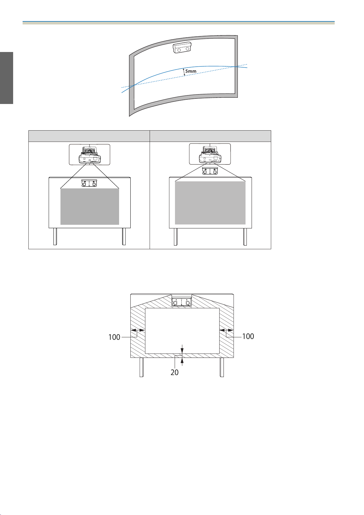
A flat, smooth, unwarped surface with no unevenness on the screen surface of more than 5 mm.
5
Page 8
Using the Product Safely
•
When installing on a whiteboard, install the Touch Unit within the frame of the whiteboard.
Correct installation position Incorrect installation position
•
When installing the Touch Unit, make sure there are no obstacles, such as cables, or protruding items such as
whiteboard trays, holders, or thick frames in the shaded areas in the following figure. The Touch Unit will not operate
correctly.
[Unit: mm]
6
Page 9

Contents
Using the Product Safely
Safety Instructions .................... 1
Safety indications.......................1
Explanation of Symbols ...................1
Safety Precautions for Installation............ 1
Notes on handling the Touch Unit (EB-1430Wi
only)................................. 3
About This Installation Guide ...............4
Choosing an Installation Location ...... 5
Projector installation location............... 5
Control Pad installation location.............5
Touch Unit installation location (EB-1430Wi only)
..................................... 5
Installation Guide
Installation Work Flow ................ 9
Package Contents .................... 10
Setting plate..........................10
When Projected Image is Smaller than 75 Inches
....................................20
16:10 projected image................. 21
16:9 projected image .................. 21
4:3 projected image ................... 22
When Projected Image is Larger than 75 Inches
....................................23
16:10 projected image................. 24
16:9 projected image .................. 25
4:3 projected image ................... 25
Installing the Setting Plate ........... 27
Connecting Devices ..................... 27
Necessary cables ..................... 27
Installation Procedure................... 30
Disassemble the parts.................30
Assemble the parts ................... 30
Install the wall plate on the wall.......... 32
Determine the projection distance, and then
pass the cables through the setting plate . . . . 34
Control Pad........................... 11
Touch Unit (EB-1430Wi only) ...............11
Specifications ....................... 12
Setting plate..........................12
Wall plate.......................... 12
Vertical slide adjustment range ...........13
Horizontal slide adjustment range......... 13
Forward/backward slide adjustment range
.................................. 13
Control Pad........................... 14
Control Pad (external dimensions/weight)
.................................. 14
Cable routing holes................... 14
Touch Unit (EB-1430Wi only) ...............15
Touch Unit (external dimensions/weight)
.................................. 15
Attached labels...................... 15
Attaching the setting plate to the wall plate
.................................. 36
Securing the projector to the setting plate
.................................. 38
Adjusting the Projected Image.............40
Adjusting the Projection Position......... 40
Fine-tuning the Focus................. 46
Calibrating the pen................... 47
Attaching the Covers .................... 51
Installing the Control Pad ............ 53
Installation Procedure................... 53
Installing the Touch Unit (EB-1430Wi
only) ................................ 56
Installation Procedure................... 56
Angle Adjustment ......................60
Touch Calibration ......................71
Laser diffusion port ...................16
Projection Distance Table ............ 17
Figures of Installation Dimensions ...........17
When installing the Touch Unit (EB-1430Wi
only)..............................17
When installing the Control Pad ..........19
Appendix
Batch Setup Function ................ 75
Saving settings to the USB flash drive........75
Reflecting saved settings to other projectors
....................................76
When Setup Fails ....................... 77
7
Page 10

Contents
Using the Interactive Function when
Multiple Projectors are Installed . . . . . . 79
Attaching a Security Cable ............ 80
General Notice ...................... 81
8
Page 11

Installation Guide
Installation Work Flow
Follow the procedures below to mount the projector on a wall.
Installing the Setting Plate and the Projector (s p.27)
a
Adjusting the Projected Image (s p.40)
b
Calibrating the Interactive Pen (s p.47)
c
Installing the Control Pad (s p.53)
d
When installing the Touch Unit, finish installing the projector first, and then follow the procedures below
(EB-1430Wi only).
Installing the Touch Unit (s p.56)
a
Adjusting the Angle of Laser Diffusion (s p.60)
b
Performing Touch Calibration (s p.71)
c
9
Page 12
Installation Guide
Package Contents
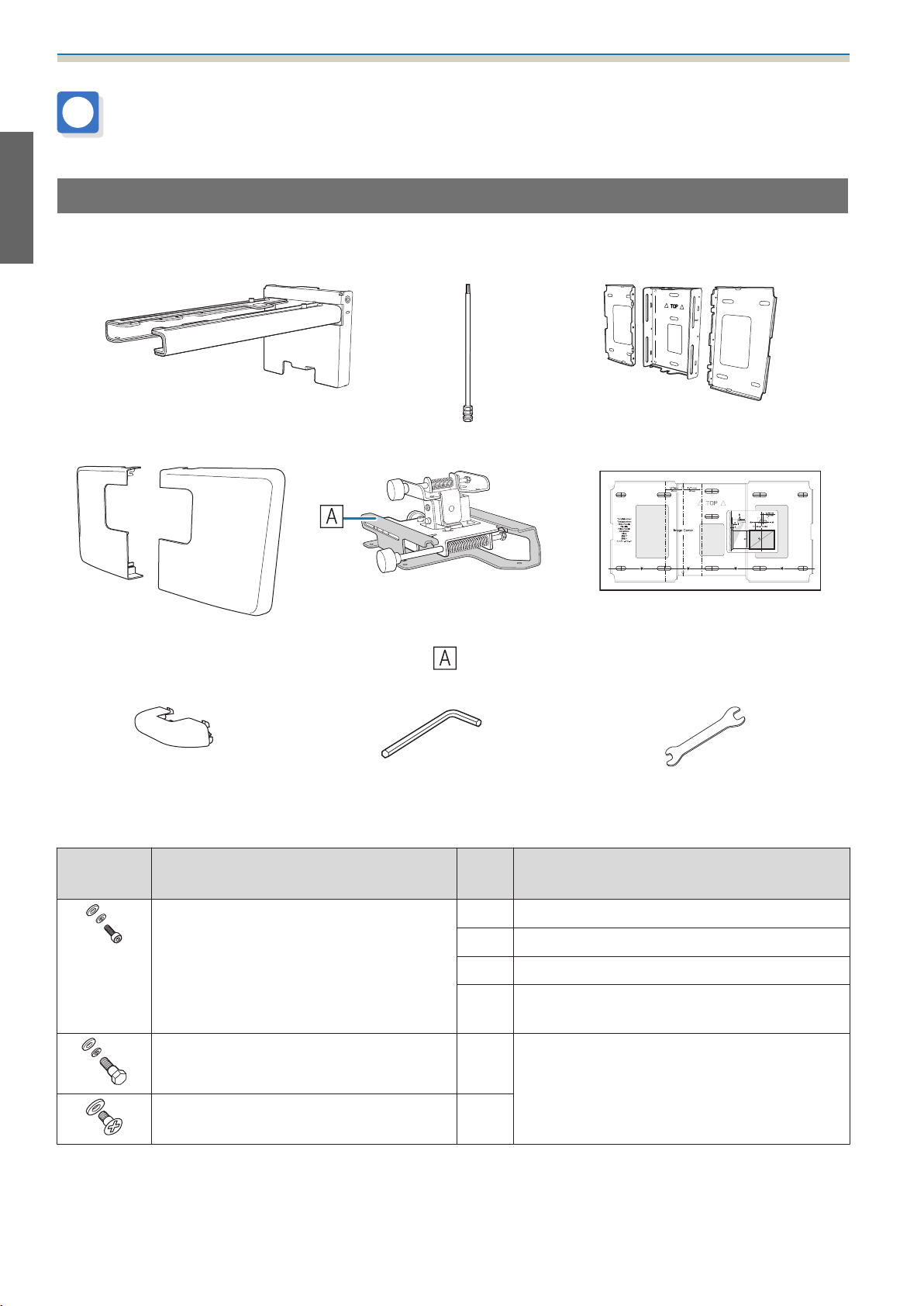
Setting plate
The following supplied items are necessary to mount the projector on a wall. Confirm that you have all items
before beginning.
Setting plate Hexagonal axis Wall plate
Wall plate cover 3-axis adjustment unit
*The slide plate (
ing shipping.
End cap Hexagon wrench (for M4) Open-ended spanner
Shape Name
M4 x 12 mm hexagon socket head cap bolt
with washer/spring washer
M6 x 20 mm hexagon shoulder head bolt
with washer/spring washer
Template sheet
) is secured dur‐
Quan‐
(for installing the wall plate)
13 mm (for M8 and M6),
6 mm (for hexagonal axis)
Application
tity
6For wall plate assembly
4 For 3-axis adjustment unit/arm installation
4 For slide plate/projector installation
2 For slide plate/3-axis adjustment unit installa‐
tion (attached during shipping)
1 For setting plate/wall plate installation
M6 x 20 mm cross recessed head shoulder
screws with plastic washers
•
Use the bolts or screws supplied with this product to install it as directed in this guide. Do not substitute these bolts
with any other types.
•
You need to use commercially available M10 x 60 mm anchors (at least 3) to attach the wall plate to the wall.
•
Gather the tools and parts you need before you begin installation.
3
10
Page 13
Installation Guide
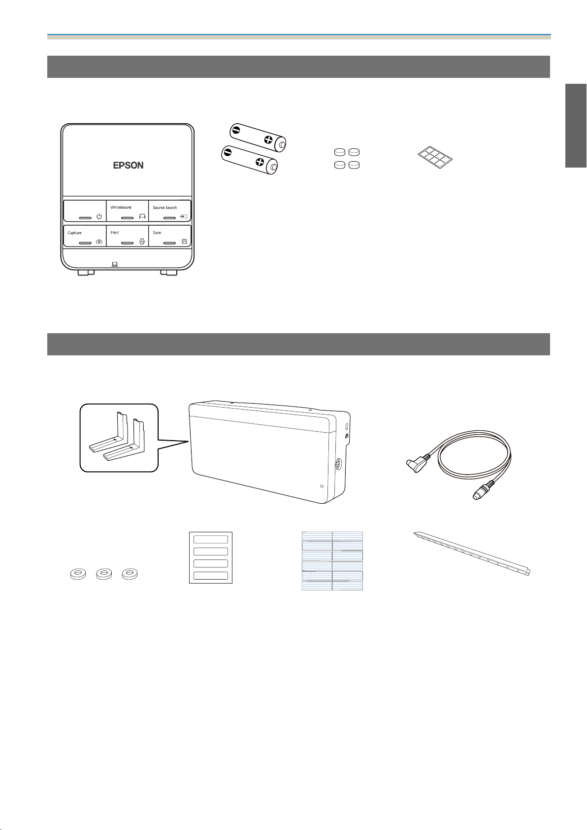
Control Pad
The following supplied products are necessary when attaching the Control Pad. Confirm that you have all
items before beginning.
AA size batteries
(x2)
Control Pad main unit
Rubber feet Port protection
stickers
When installing the Control Pad on a wall and so on, prepare commercially available M4 screws (20 mm x4).
Touch Unit (EB-1430Wi only)
The following supplied products are necessary when attaching the Touch Unit. Confirm that you have all
items before beginning.
Touch Unit/Markers x2 (attached to Touch Unit) Touch Unit connection cable
Spacer for screw hole x3 Label x4 Tape (approx. 6 cm) for secur‐
ing the marker x12
Infrared deflector
(approx. 28.5 cm) x8
When installing the Touch Unit on a non-magnetic surface, prepare three M4 screws.
11
Page 14
Installation Guide
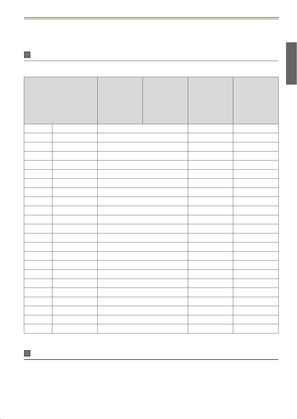
Specifications
Setting plate
Item Specification Remark Reference
Setting plate weight Approx. 8.1 kg Setting plate (3.0 kg), 3-axis adjustment unit
(1.2 kg), slide plate (0.8 kg), wall plate (2.7 kg),
wall plate cover and end cap (0.4 kg)
Maximum load capacity 7 kg
Page
Forward/backward slide ad‐
justment range
Vertical slide adjustment range ±38 mm See the fig‐
Horizontal roll adjustment
range
Horizontal rotation adjustment
range
Vertical tilt adjustment range ±3° Fine adjustments possible with adjustment
Horizontal slide adjustment
range
0 to 360 mm Arm slide adjustment range: 0 to 273 mm
Adjustment for 3-axis adjustment unit instal‐
lation position: 87 mm
±3° Fine adjustments possible with adjustment
dial
±8° Fine adjustments possible with adjustment
dial
dial
±45 mm See the fig‐
See the fig‐
ure below
ure below
s
p.40
s
p.40
s
p.40
ure below
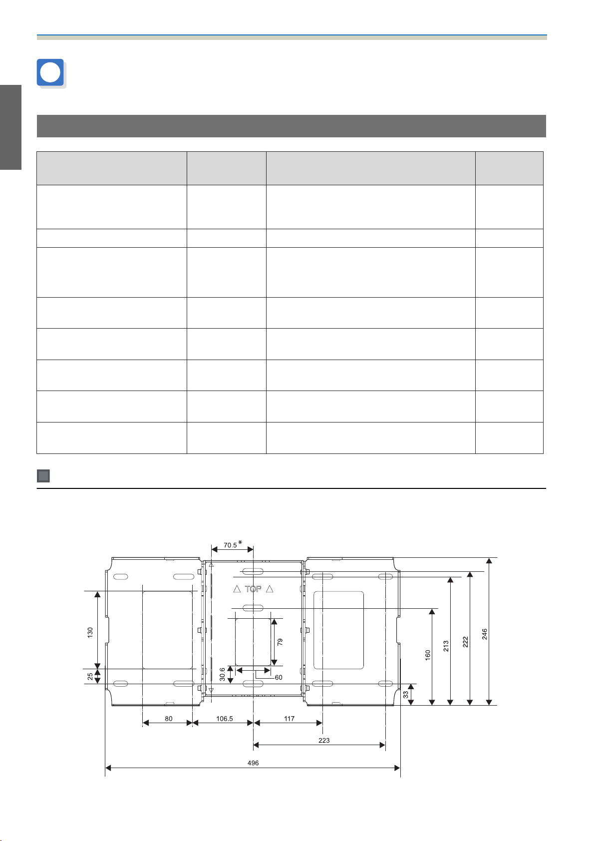
Wall plate
The following figure shows three wall plates connected to form one plate (separate when shipped).
[Unit: mm]
*
Offset value for the position of the center of the projected image and the center of the wall plate
12
Page 15
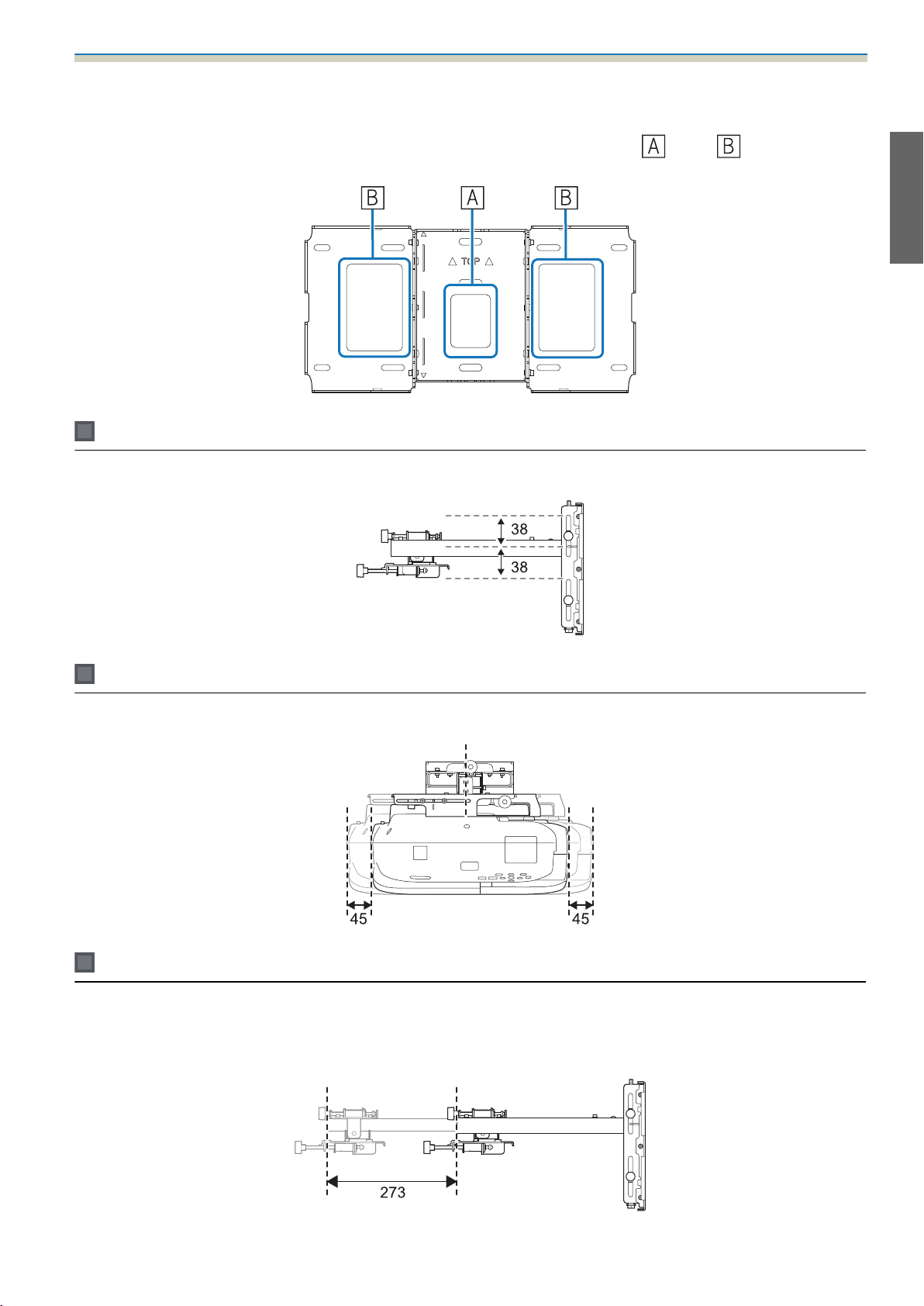
Installation Guide
Cable routing holes
When routing cables to connect to the projector through a wall, use positions ( ) and ( ) in the following
figure as the cable routing holes.
Vertical slide adjustment range
[Unit: mm]
Horizontal slide adjustment range
Forward/backward slide adjustment range
Arm slide adjustment range
[Unit: mm]
[Unit: mm]
13
Page 16
Installation Guide
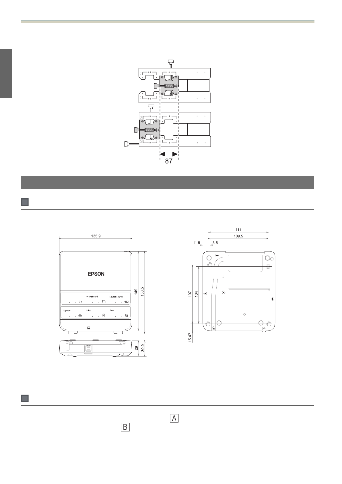
Adjustment range for 3-axis adjustment unit installation position
[Unit: mm]
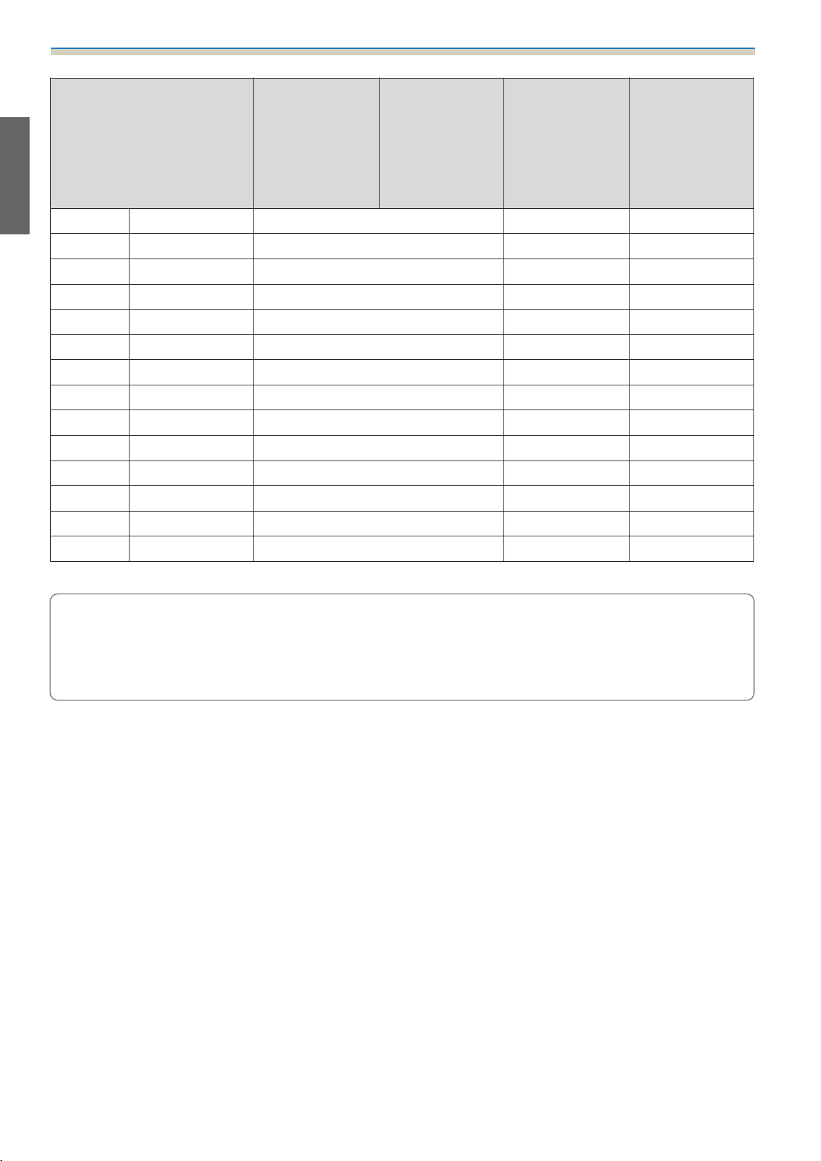
Control Pad
Control Pad (external dimensions/weight)
[Unit: mm]
•
Weight: approx. 240 g (not including batteries and rubber feet)
•
Operating temperature: 0 to +50°C (no condensation)
•
Operating temperature: -20 to +60°C (no condensation)
Cable routing holes
When routing cables through a wall, use the position ( ) in the following figure as the cable routing hole.
Otherwise, remove the cable cover (
groove at the back of the Control Pad.
) and route the cables from there. Route the printer cable along the
14
Page 17
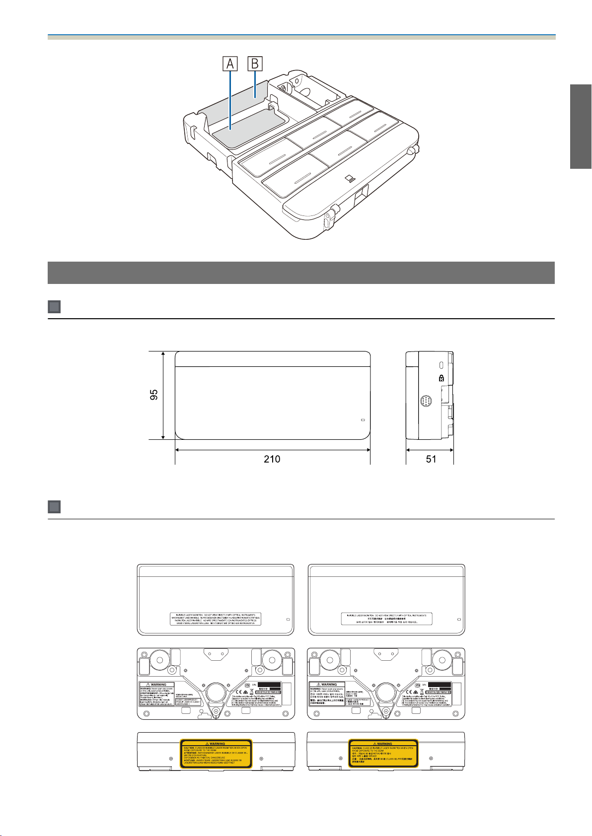
Touch Unit (EB-1430Wi only)
Touch Unit (external dimensions/weight)
Installation Guide
[Unit: mm]
The Touch Unit weighs 450 g.
Attached labels
The Touch Unit is a Class 1 laser product that conforms to the JIS C 6802:2011 standard. There are warning
labels affixed to the Touch Unit to indicate that it is a Class 1 laser product.
15
Page 18
Installation Guide
The labels contain the following information.
•
CLASS 1 LASER PRODUCT
•
WARNING: Never open any covers on this unit. Laser product inside.
•
Warning:
•
CAUTION: CLASS 3B INVISIBLE LASER RADIATION WHEN OPEN.
•
AVOID EXPOSURE TO THE BEAM
Laser diffusion port
The laser beam is diffused from the laser diffusion ports at the back of the Touch Unit.
16
Page 19
Installation Guide
Projection Distance Table
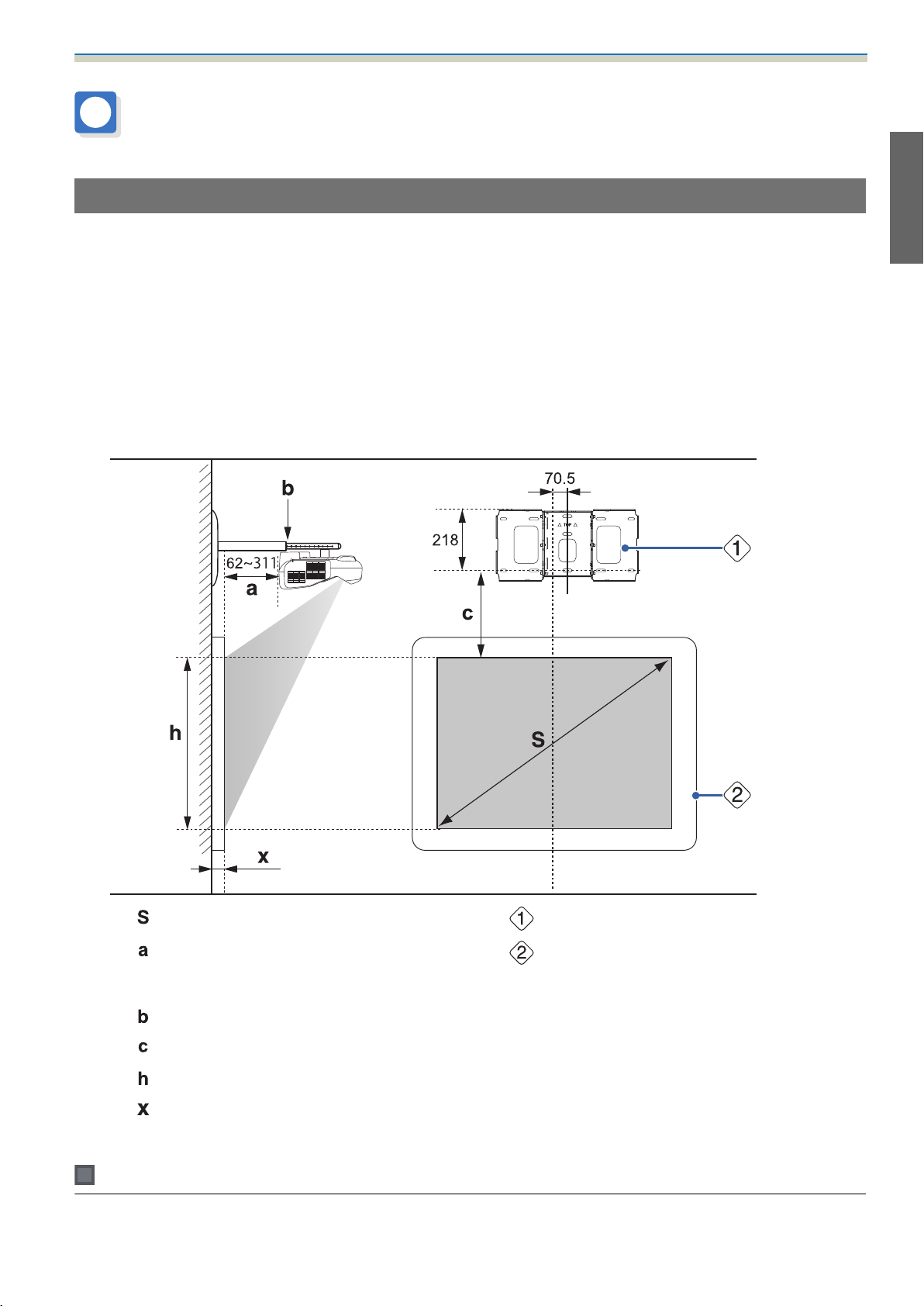
Figures of Installation Dimensions
To find the appropriate screen size, see the following figures when installing. The values are only rough
estimates.
The recommended range for the projection distance (a) is 62 to 311 mm.
The offset value for the position of the center of the projected image and the center of the wall plate is 70.5
mm.
When the projected image size (S) is 75 inches or more, the scale on the arm slide (b) is equal to the projection
distance (a).
The numbers for (a) and (b) differ if the projected image size (S) is less than 75 inches.
[Unit: mm]
Projected image size
:
Minimum projection distance (Wide: maxi‐
:
mum zoom)
to maximum (Tele: minimum zoom)
Numbers on the arm slide scale
:
Distance from projected image to wall plate
:
Height of projected image
:
Distance from surface of screen to wall (100
:
mm or less)
Wall plate
:
Screen
:
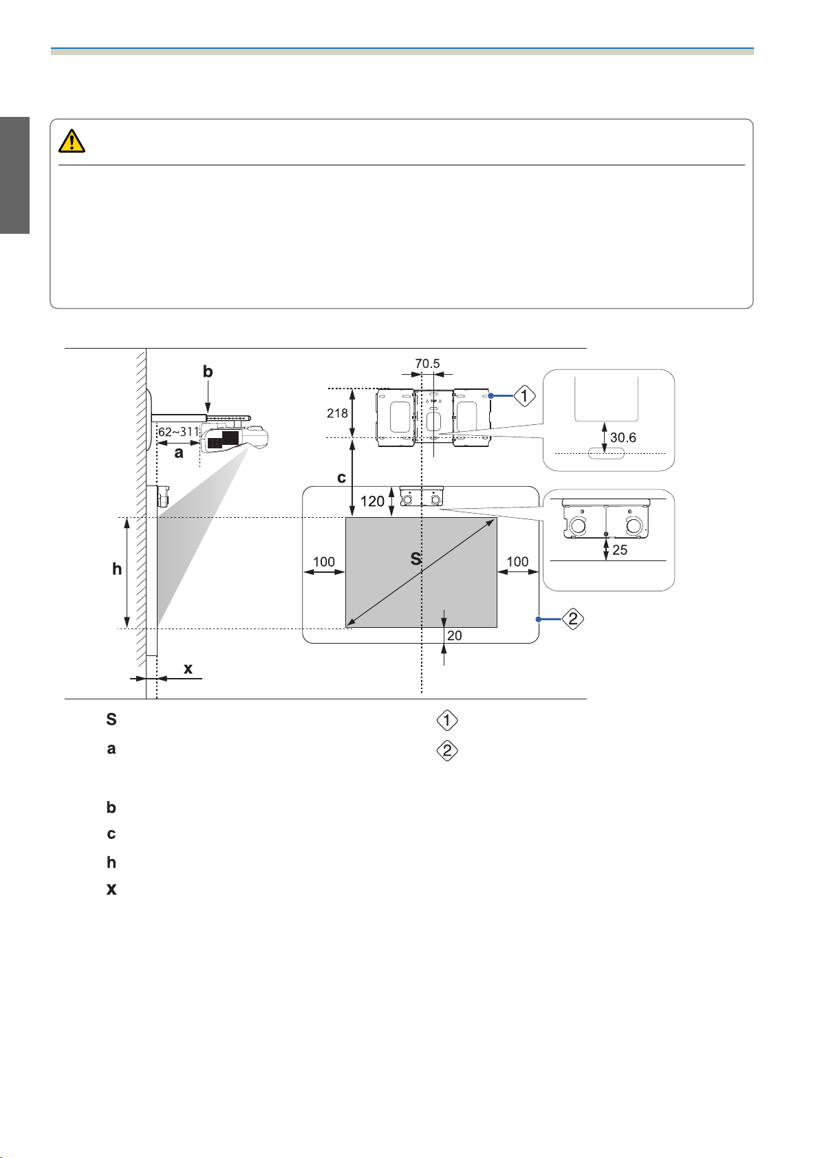
When installing the Touch Unit (EB-1430Wi only)
When installing the Touch Unit, install it on the screen that is being used for projection.
17
Page 20
Installation Guide
You need at least 120 mm distance between the top edge of the projected image and the top edge of the
actual screen to install the Touch Unit.
Caution
Leave the following gaps around the edge of the screen.
•
From the top of the projected image to the bottom of the Touch Unit: 25 mm
•
From the edges of the projected image to the edges of the screen: At least 100 mm left and right
•
From the bottom of the projected image to the bottom of the screen: At least 20 mm
If there are obstacles such as cables, whiteboard trays, holders, or frames within the areas noted above,
the Touch Unit will not operate correctly.
[Unit: mm]
Projected image size
:
Minimum projection distance (Wide: maxi‐
:
mum zoom)
to maximum (Tele: minimum zoom)
Numbers on the arm slide scale
:
Distance from projected image to wall plate
:
Height of projected image
:
Distance from surface of screen to wall (100
:
mm or less)
Wall plate
:
Screen
:
18
Page 21

Installation Guide
Aspect ratio for standard projected image
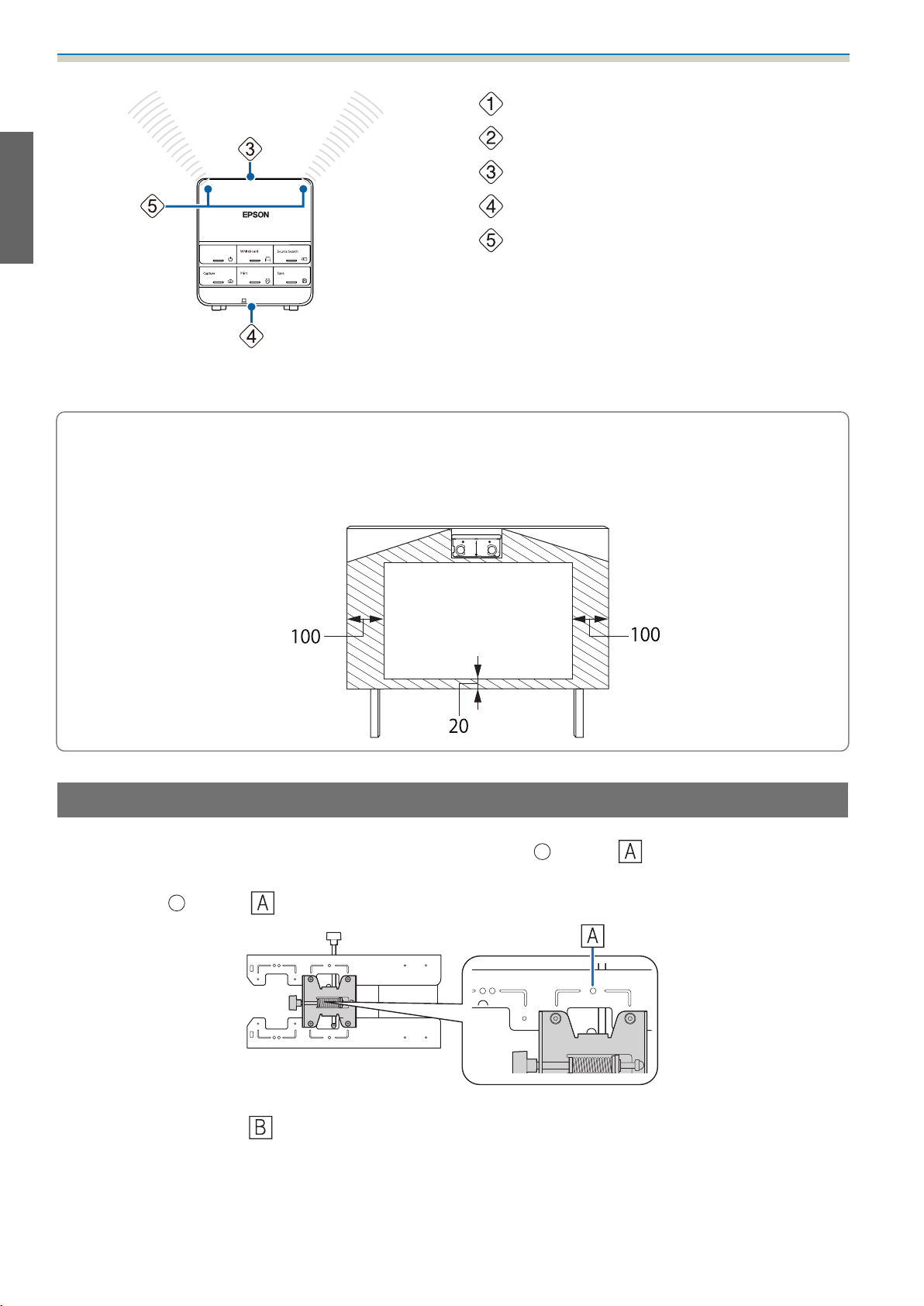
When installing the Control Pad
When installing the Control Pad, make sure there is enough space in the surrounding area as shown in the
following figure. Because the top cover opens from the left-hand side, you need space on the left-hand side
of the Control Pad.
[Unit: mm]
When supplying power using batteries, install the Control Pad within the shaded range shown in the following
figure.
19
Page 22
Installation Guide
Center of screen
:
Top of projector
:
Top of Control Pad
:
Bottom of Control Pad
:
Remote control light-emitting area
:
Align the top of the projector with the top of the Control Pad, and point the Control Pad's remote control
light-emitting area at the projector.
When installing the Touch Unit, do not install the Control Pad on the projection screen and the
surrounding area (shaded area in the following figure) (EB-1430Wi only). The Touch Unit will not
c
operate correctly.
[Unit: mm]
When Projected Image is Smaller than 75 Inches
Mount the 3-axis adjustment unit at the position marked with a stamp ( ).
The projection distance table provides the figures when mounting the 3-axis adjustment unit at the position
marked with a
stamp ( ). The numbers on the arm slide scale (b) differ from the projection distance (a).
The distance (c) from the projected image to the wall plate is the number given when the vertical slide is set
to the standard position (
Match the notch on the setting plate to the position of the stamp on the wall plate.
).
20
Page 23
16:10 projected image
Installation Guide
[Unit: cm]
S
Projected image size
60" 129.2x80.8 6.2 - 19.3 14.9 - 28.0 17.4 80.8
61" 131.4x82.1 6.9 - 20.1 15.6 - 28.8 17.7 82.1
62" 133.5x83.5 7.5 - 20.9 16.2 - 29.6 17.9 83.5
63" 135.7x84.8 8.1 - 21.8 16.8 - 30.5 18.2 84.8
64" 137.9x86.2 8.7 - 22.6 17.4 - 31.3 18.5 86.2
65" 140.0x87.5 9.3 - 23.5 18.0 - 32.2 18.7 87.5
66" 142.2x88.8 10.0 - 24.3 18.7 - 33.0 19.0 88.8
67" 144.3x90.2 10.6 - 25.1 19.3 - 33.8 19.3 90.2
68" 146.5x91.5 11.2 - 26.0 19.9 - 34.7 19.5 91.5
69" 148.6x92.9 11.8 - 26.8 20.5 - 35.5 19.8 92.9
70" 150.8x94.2 12.4 - 27.6 21.1 - 36.3 20.1 94.2
Projection Dis‐
Minimum (Wide)
a
tance
to Maximum
(Tele)
b
Numbers on the
arm slide scale
c
Distance from
projected image
to wall plate
h
Height of projec‐
ted image
71" 152.9x95.6 13.1 - 28.5 21.8 - 37.2 20.3 95.6
72" 155.1x96.9 13.7 - 29.3 22.4 - 38.0 20.6 96.9
73" 157.2x98.3 14.3 - 30.2 23.0 - 38.9 20.9 98.3
74" 159.4x99.6 14.9 - 31.0 23.6 - 39.7 21.1 99.6
Images smaller than 60 inches are not projected correctly.
16:9 projected image
S
Projected image size
59" 130.6x73.5 6.6 - 19.8 15.3 - 28.5 21.7 73.5
Projection Dis‐
Minimum (Wide)
a
tance
to Maximum
(Tele)
b
Numbers on the
arm slide scale
c
Distance from
projected image
to wall plate
[Unit: cm]
h
Height of projec‐
ted image
21
Page 24
Installation Guide
S
Projected image size
60" 132.8x74.7 7.3 - 20.7 16.0 - 29.4 22.0 74.7
61" 135.0x76.0 7.9 - 21.5 16.6 - 30.2 22.3 76.0
62" 137.3x77.2 8.6 - 22.4 17.3 - 31.1 22.7 77.2
63" 139.5x78.5 9.2 - 23.3 17.9 - 32.0 23.0 78.5
64" 141.7x79.7 9.8 - 24.1 18.5 - 32.8 23.4 79.7
65" 143.9x80.9 10.5 - 25.0 19.2 - 33.7 23.7 80.9
66" 146.1x82.2 11.1 - 25.8 19.8 - 34.5 24.1 82.2
67" 148.3x83.4 11.7 - 26.7 20.4 - 35.4 24.4 83.4
68" 150.5x84.7 12.4 - 27.6 21.1 - 36.3 24.8 84.7
69" 152.8x85.9 13.0 - 28.4 21.7 - 37.1 25.1 85.9
70" 155.0x87.2 13.7 - 29.3 22.4 - 38.0 25.4 87.2
Projection Dis‐
Minimum (Wide)
a
tance
to Maximum
(Tele)
b
Numbers on the
arm slide scale
c
Distance from
projected image
to wall plate
h
Height of projec‐
ted image
71" 157.2x88.4 14.3 - 30.1 23.0 - 38.8 25.8 88.4
72" 159.4x89.7 14.9 - 31.0 23.6 - 39.7 26.1 89.7
73" 161.6x90.9 15.6 - 31.1 24.3 - 39.8 26.5 90.9
74" 163.8x92.1 16.2 - 31.1 24.9 - 39.8 26.8 92.1
Images smaller than 59 inches are not projected correctly.
4:3 projected image
S
Projected image size
53" 107.7x80.8 6.2 - 19.3 14.9 - 28.0 17.4 80.8
54" 109.7x82.3 6.9 - 20.2 15.6 - 28.9 17.7 82.3
55" 111.8x83.8 7.6 - 21.2 16.3 - 29.9 18.0 83.8
Projection Dis‐
Minimum (Wide)
a
tance
to Maximum
(Tele)
b
Numbers on the
arm slide scale
c
Distance from
projected image
to wall plate
[Unit: cm]
h
Height of projec‐
ted image
56" 113.8x85.3 8.3 - 22.1 17.0 - 30.8 18.3 85.3
57" 115.8x86.9 9.1 - 23.1 17.8 - 31.8 18.6 86.9
58" 117.9x88.4 9.8 - 24.0 18.5 - 32.7 18.9 88.4
59" 119.9x89.9 10.5 - 25.0 19.2 - 33.7 19.2 89.9
60" 121.9x91.4 11.2 - 25.9 19.9 - 34.6 19.5 91.4
61" 124.0x93.0 11.9 - 26.9 20.6 - 35.6 19.8 93.0
62" 126.0x94.5 12.6 - 27.8 21.3 - 36.5 20.1 94.5
63" 128.0x96.0 13.3 - 28.8 22.0 - 37.5 20.4 96.0
22
Page 25
Installation Guide
S
Projected image size
64" 130.0x97.5 14.0 - 29.7 22.7 - 38.4 20.7 97.5
65" 132.1x99.1 14.7 - 30.7 23.4 - 39.4 21.0 99.1
66" 134.1x100.6 15.4 - 31.1 24.1 - 39.8 21.3 100.6
67" 136.1x102.1 16.1 - 31.1 24.8 - 39.8 21.6 102.1
68" 138.2x103.6 16.8 - 31.1 25.5 - 39.8 21.9 103.6
69" 140.2x105.2 17.5 - 31.1 26.2 - 39.8 22.2 105.2
70" 142.2x106.7 18.2 - 31.1 26.9 - 39.8 22.5 106.7
71" 144.3x108.2 18.9 - 31.1 27.6 - 39.8 22.8 108.2
72" 146.3x109.7 19.6 - 31.1 28.3 - 39.8 23.2 109.7
73" 148.3x111.3 20.3 - 31.1 29.0 - 39.8 23.5 111.3
74" 150.4x112.8 21.0 - 31.1 29.7 - 39.8 23.8 112.8
Projection Dis‐
Minimum (Wide)
a
tance
to Maximum
(Tele)
b
Numbers on the
arm slide scale
c
Distance from
projected image
to wall plate
h
Height of projec‐
ted image
Images smaller than 53 inches are not projected correctly.
•
The values are only rough estimates. The value may differ depending on the location where you place
c
the projector.
•
When projecting in Tele, the quality of the projected images may decrease.
•
When projecting images at 4:3, the images are resized automatically and the quality of the projected
images may decrease.
When Projected Image is Larger than 75 Inches
Mount the 3-axis adjustment unit at the position marked with a stamp ( ).
The projection distance table provides the figures when mounting the 3-axis adjustment unit at the position
marked with a
distance (a).
stamp ( ). The numbers on the arm slide scale (b) is the same as the projection
The distance (c) from the projected image to the wall plate is the number given when the vertical slide is set
to the standard position (
).
Match the notch on the setting plate to the position of the stamp on the wall plate.
23
Page 26
Installation Guide
16:10 projected image
[Unit: cm]
S
Projected image size
75" 161.5x101.0 15.5 - 31.1 21.4 101.0
76" 163.7x102.3 16.2 - 31.1 21.7 102.3
77" 165.9x103.7 16.8 - 31.1 21.9 103.7
78" 168.0x105.0 17.4 - 31.1 22.2 105.0
79" 170.2x106.3 18.0 - 31.1 22.5 106.3
80" 172.3x107.7 18.7 - 31.1 22.7 107.7
81" 174.5x109.0 19.3 - 31.1 23.0 109.0
82" 176.6x110.4 19.9 - 31.1 23.3 110.4
83" 178.8x111.7 20.5 - 31.1 23.5 111.7
84" 180.9x113.1 21.1 - 31.1 23.8 113.1
85" 183.1x114.4 21.8 - 31.1 24.1 114.4
Projection Dis‐
Minimum (Wide)
a
tance
to Maximum
(Tele)
b
Numbers on the
arm slide scale
c
Distance from
projected image
to wall plate
h
Height of projec‐
ted image
86" 185.2x115.8 22.4 - 31.1 24.3 115.8
87" 187.4x117.1 23.0 - 31.1 24.6 117.1
88" 189.5x118.5 23.6 - 31.1 24.9 118.5
89" 191.7x119.8 24.2 - 31.1 25.2 119.8
90" 193.9x121.2 24.9 - 31.1 25.4 121.2
91" 196.0x122.5 25.5 - 31.1 25.7 122.5
92" 198.2x123.9 26.1 - 31.1 26.0 123.9
93" 200.3x125.2 26.7 - 31.1 26.2 125.2
94" 202.5x126.5 27.3 - 31.1 26.5 126.5
95" 204.6x127.9 28.0 - 31.1 26.8 127.9
96" 206.8x129.2 28.6 - 31.1 27.0 129.2
97" 208.9x130.6 29.2 - 31.1 27.3 130.6
98" 211.1x131.9 29.8 - 31.1 27.6 131.9
99" 213.2x133.3 30.4 - 31.1 27.8 133.3
100" 215.4x134.6 31.1* 28.1 134.6
24
Page 27
*
Figure for Wide (maximum zoom).
Images larger than 100 inches are not projected correctly.
16:9 projected image
Installation Guide
[Unit: cm]
S
Projected image size
75" 166.0x93.4 16.8 - 31.1 27.2 93.4
76" 168.2x94.6 17.5 - 31.1 27.5 94.6
77" 170.5x95.9 18.1 - 31.1 27.8 95.9
78" 172.7x97.1 18.8 - 31.1 28.2 97.1
79" 174.9x98.4 19.4 - 31.1 28.5 98.4
80" 177.1x99.6 20.0 - 31.1 28.9 99.6
81" 179.3x100.9 20.7 - 31.1 29.2 100.9
82" 181.5x102.1 21.3 - 31.1 29.6 102.1
83" 183.7x103.4 21.9 - 31.1 29.9 103.4
84" 186.0x104.6 22.6 - 31.1 30.3 104.6
85" 188.2x105.8 23.2 - 31.1 30.6 105.8
Projection Dis‐
Minimum (Wide)
a
tance
to Maximum
(Tele)
b
Numbers on the
arm slide scale
c
Distance from
projected image
to wall plate
h
Height of projec‐
ted image
86" 190.4x107.1 23.9 - 31.1 30.9 107.1
87" 192.6x108.3 24.5 - 31.1 31.3 108.3
88" 194.8x109.6 25.1 - 31.1 31.6 109.6
89" 197.0x110.8 25.8 - 31.1 32.0 110.8
90" 199.2x112.1 26.4 - 31.1 32.3 112.1
91" 201.5x113.3 27.0 - 31.1 32.7 113.3
92" 203.7x114.6 27.7 - 31.1 33.0 114.6
93" 205.9x115.8 28.3 - 31.1 33.3 115.8
94" 208.1x117.1 29.0 - 31.1 33.7 117.1
95" 210.3x118.3 29.6 - 31.1 34.0 118.3
96" 212.5x119.5 30.2 - 31.1 34.4 119.5
97" 214.7x120.8 30.9 - 31.1 34.7 120.8
Images larger than 97 inches are not projected correctly.
4:3 projected image
[Unit: cm]
25
Page 28
Installation Guide
S
Projected image size
75" 152.4x114.3 21.7 - 31.1 24.1 114.3
76" 154.4x115.8 22.4 - 31.1 24.4 115.8
77" 156.5x117.3 23.1 - 31.1 24.7 117.3
78" 158.5x118.9 23.8 - 31.1 25.0 118.9
79" 160.5x120.4 24.5 - 31.1 25.3 120.4
80" 162.6x121.9 25.2 - 31.1 25.6 121.9
81" 164.6x123.4 25.9 - 31.1 25.9 123.4
82" 166.6x125.0 26.6 - 31.1 26.2 125.0
83" 168.7x126.5 27.3 - 31.1 26.5 126.5
84" 170.7x128.0 28.0 - 31.1 26.8 128.0
85" 172.7x129.5 28.7 - 31.1 27.1 129.5
Projection Dis‐
Minimum (Wide)
a
tance
to Maximum
(Tele)
b
Numbers on the
arm slide scale
c
Distance from
projected image
to wall plate
h
Height of projec‐
ted image
86" 174.8x131.1 29.4 - 31.1 27.4 131.1
87" 176.8x132.6 30.1 - 31.1 27.7 132.6
88" 178.8x134.1 30.8 - 31.1 28.0 134.1
Images larger than 88 inches are not projected correctly.
•
The values are only rough estimates. The value may differ depending on the location where you place
c
the projector.
•
When projecting in Tele, the quality of the projected images may decrease.
•
When projecting images at 4:3, the images are resized automatically and the quality of the projected
images may decrease.
26
Page 29
Installation Guide
Installing the Setting Plate
Connecting Devices
Necessary cables
Prepare the necessary cables according to the devices being used.
•
Power cord supplied (necessary)
•
USB cable supplied
•
Touch Unit connection cable supplied (EB-1430Wi only)
•
Optional computer cables, Remote control cable set, and other cables (prepare according to the connected devices)
For details, see the projector's User's Guide (on the Document CD-ROM).
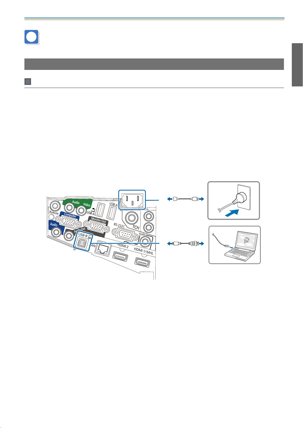
Necessary cables when using the Easy Interactive Function
When performing mouse operations using the Easy Interactive Function, you need a power cord and USB
cable. Even when projecting using a computer cable, a USB cable is necessary to perform mouse operations.
27
Page 30
Installation Guide
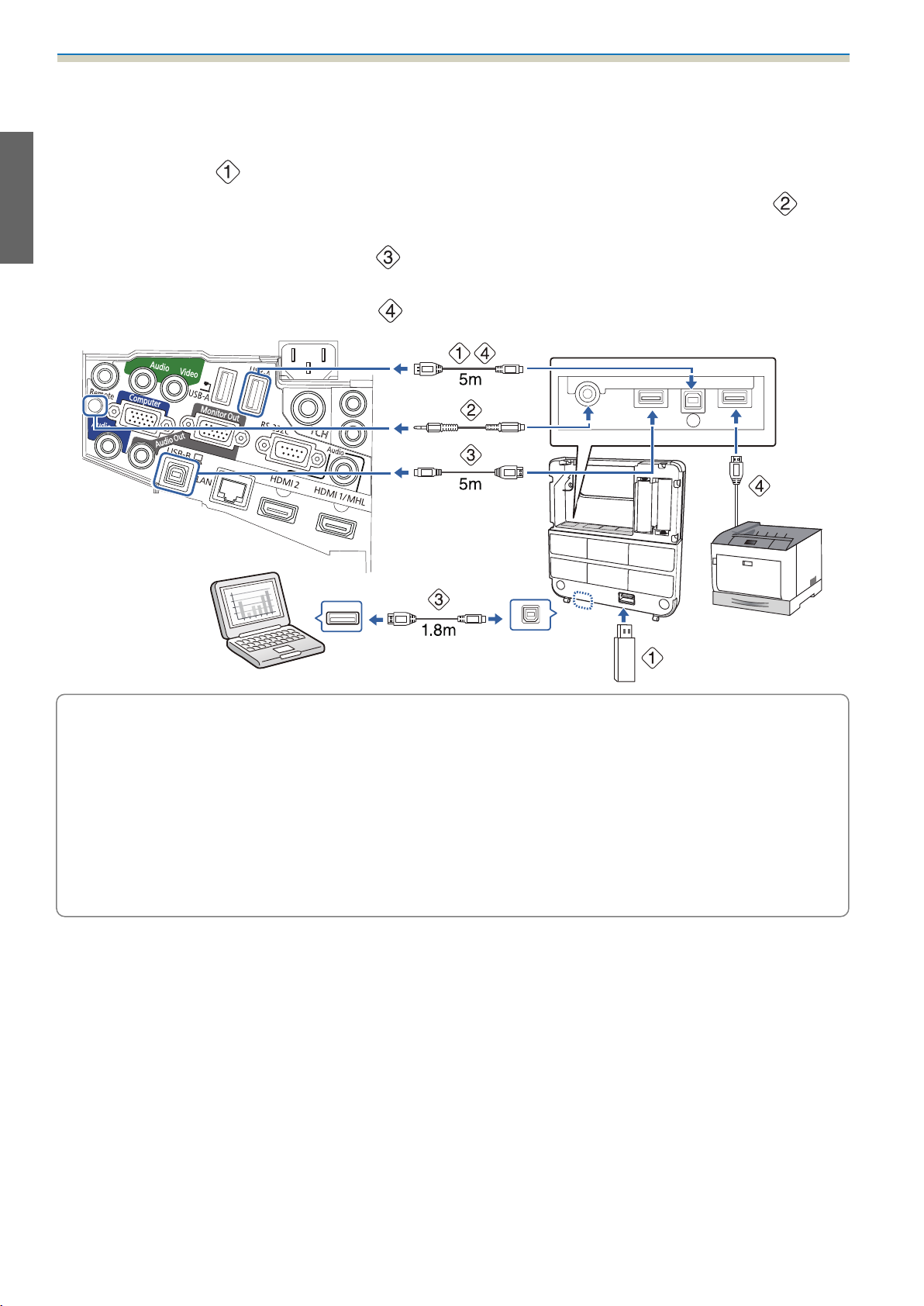
Necessary cables when installing the Control Pad
•
When projecting images from a USB storage device, or when saving data to the USB storage device, you need the
USB cable supplied (
•
When supplying power from the projector, you need the optional Remote control cable set (ELPKC28) ( ).
•
When projecting computer images (USB Display), or performing mouse operations using the Easy Interactive
Function, you need the USB cable supplied (
•
When printing the projected image, you need the USB cable supplied. To connect the Control Pad and the printer,
use the USB cable supplied with the printer (
).
).
).
The following Epson projectors can be connected to the Control Pad. Check the rating label on the
projector.
c
•
H480x (where x is one letter from A to Z)
•
H481x (where x is one letter from A to Z)
•
H612x (where x is one letter from A to Z)
•
H665x (where x is one letter from A to Z)
This information is current as of May 30th, 2014. If you want to connect a different projector or if you
have any queries, contact your local dealer from the Epson Projector Contact List provided on the
Document CD-ROM.
28
Page 31

Installation Guide
Necessary cables when installing the Touch Unit (EB-1430Wi only)
You need the supplied Touch Unit connection cable when installing the Touch Unit and connecting it to the
projector. Operations are not performed correctly with a commercially available cable.
The shape of the plug that connects to the projector and the plug that connects to the Touch Unit differ. See
the following figure to connect to the correct ports.
Prepare cables for the connected devices (example)
Document camera
Dedicated USB cable (supplied with document cam‐
era)
External speakers
Audio cable (commercially available)
Computer
Computer cable (optional accessory)
LAN device
LAN cable (commercially available)
29
Page 32

Installation Guide
Installation Procedure
Make sure to follow the steps below to install the setting plate. If these steps are not followed, the product
could fall and cause personal injury or property damage.
Warning
Do not use adhesives, lubricants, or oils to install or adjust the setting plate. If you use adhesives to prevent
the screws from loosening or things such as lubricants or oils on the slide plate fixing part of the projector,
the case may crack and cause the projector to fall, resulting in personal injury or property damage.
Disassemble the parts
Remove the M4 bolts (x2), and then remove the slide plate from the 3-axis adjustment unit.
Assemble the parts
Assemble the three wall plates into one unit, and secure them with the M4 bolts (x6)
supplied
a
30
Page 33

b
Installation Guide
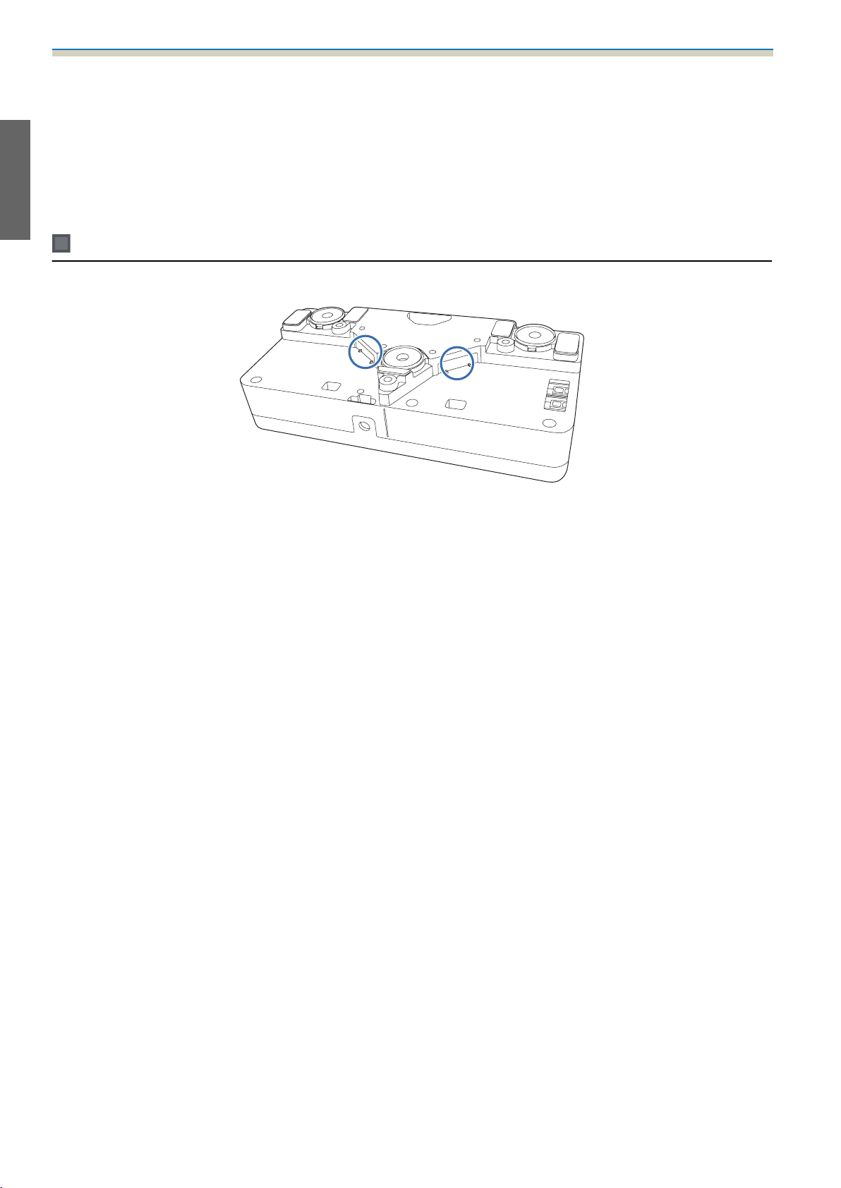
Secure the slide plate to the base of the projector with the M4 bolts (x4) supplied
Bolt installation positions
Attach the 3-axis adjustment unit to the setting plate with the M4 bolts (x4) supplied
c
•
When a projected image is smaller than 75 inches: Mount the unit at the stamp ( ).
•
When a projected image is larger than 75 inches: Mount the unit at the stamp ( ).
: Smaller than 75 inches : Larger than 75 inches
31
Page 34

Installation Guide
Install the wall plate on the wall
Determine the projection position based on the projected image size
a
See the projection distance table to calculate the projected image size (S) and the distance (c) from
the projected image to the wall plate.
s
"Projection Distance Table" p.17
We recommend marking the following positions. These will be the basis for determining the mounting
position of the wall plate.
•
Height ( ) of the distance (c) between the top edge of the projected image and the wall plate
•
Center line ( ) of the projected image
32
Page 35

Attach the template sheet to the wall
Installation Guide
b
•
Match the center line ( ) checked in step 1 to the Image Center line on the template sheet.
Confirm where the beams are within the wall, and shift the position left or right as necessary.
(The position can be shifted horizontally left or right from the center line of the projection surface up to a
maximum of 45 mm.)
•
Match the height ( ) checked in step 1 to the line on the template sheet.
[Unit: mm]
c
Determine the positions for the mounting holes for the wall plate
Secure the wall plate in at least three points.
•
If securing the wall plate in four places, make the holes indicated by A or B in the figure.
•
If securing the wall plate in three places, make the holes indicated by C in the figure.
Four mounting holes Three mounting holes
33
Page 36

Installation Guide
Drill the holes in the wall
d
e
f
Drill diameter: 10.5 mm
Pilot hole depth: 45 mm
Anchor hole depth: 40 mm
Remove the template sheet, and clean the concrete dust from the holes with a dust pump
Position the wall plate on the wall and insert M10 x 60 mm commercially available anchors
into the holes
Attach the nut and tap it with a hammer
until the core touches the top of the an‐
chor.
Tighten the nut with a commercially available spanner to secure the wall plate to the wall
g
Determine the projection distance, and then pass the cables through the setting plate
Check the following values in the projection distance table
a
•
Numbers on the arm slide scale (b)
•
Distance from surface of screen to wall (x)
s
"Projection Distance Table" p.17
34
Page 37

Loosen the M4 bolts (x2) and extend the arm slide on the setting plate
Installation Guide
b
c
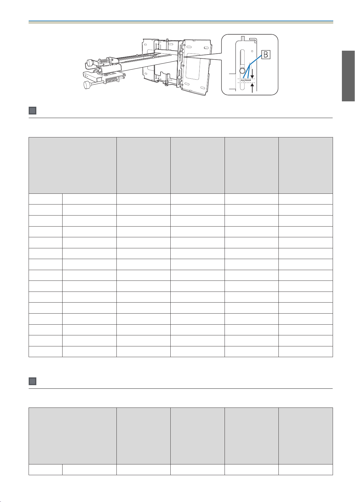
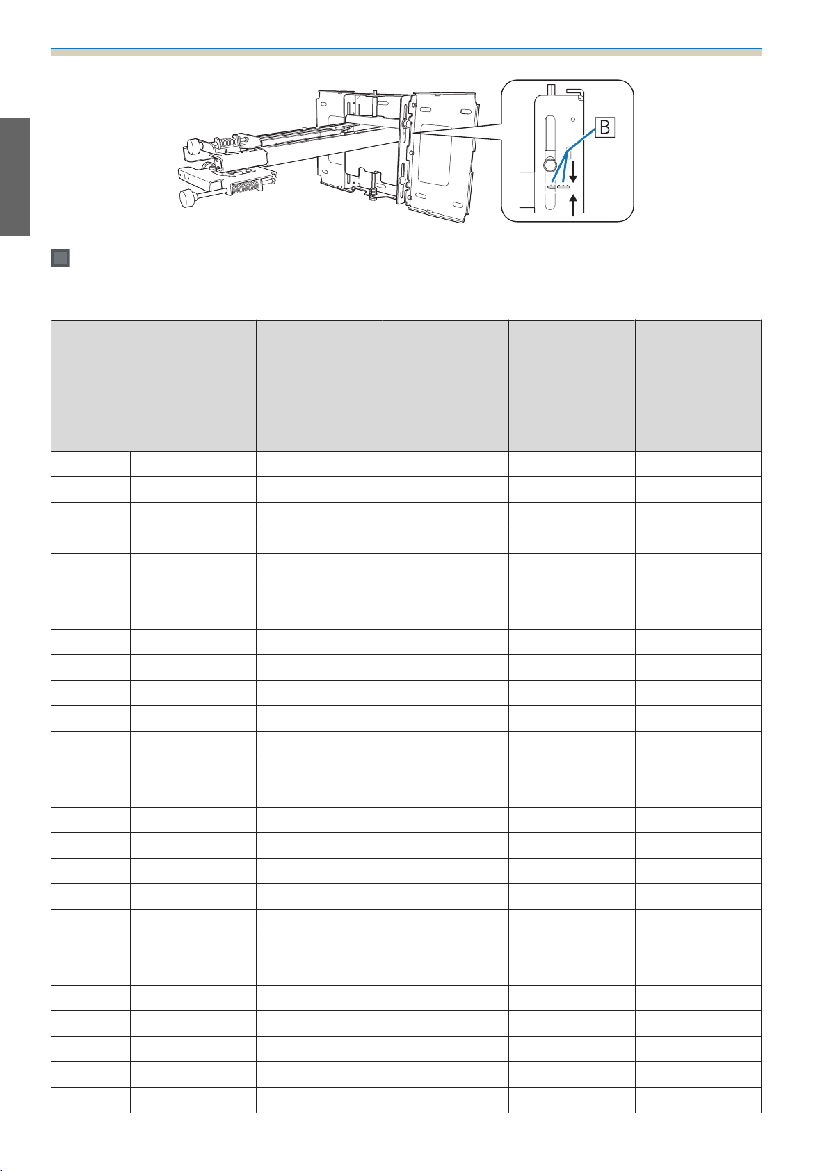
Align the slider with the combined distances of (b) and (x) that you checked in step 1.
Route the necessary cables through the setting plate
See the following figure to route the cables so that the ends of the cables that connect to the projector
are on the projector's interface side.
Warning
Do not hang the rest of the cable over the setting plate. They could fall and cause an accident.
•
Route the cables connected to the Control Pad through the setting plate.
•
c
Route the cables connected to the Touch Unit through the setting plate (EB-1430Wi only). Route
the cable so that the end that connects to the Touch Unit appears from the lower part of the
setting plate.
35
Page 38

Installation Guide
Attaching the setting plate to the wall plate
Insert the hexagonal axis into the setting plate
a
b
Mount the setting plate to the wall plate
Insert the top of the hexagonal axis into the wall plate, and then insert the M8 bolt into the slot at the
bottom.
Caution
•
Do not wire the Touch Unit connection cable into the wall (EB-1430Wi only). If it is wired into the wall,
it cannot be connected to the Touch Unit.
•
Take care not to trap the cables between the setting plate and wall plate.
36
Page 39

Secure the setting plate and the wall plate
Installation Guide
c
d
Secure the supplied M6 screws (x3) with a commercially available No.3 cross-head screwdriver, and
then lightly tighten the supplied M6 bolt (x1) with the spanner.
Adjust the vertical slide with the open-ended spanner, and align it with the standard
position (
)
•
Tightening the hexagonal axis at the top ( ) raises the setting plate, and loosening the axis lowers it.
•
Tightening the M8 bolt at the bottom ( ) lowers the setting plate, and loosening the bolt raises it.
37
Page 40

Installation Guide
Tighten the M6 bolt (x1) to fix the setting plate in position
e
Securing the projector to the setting plate
a
b
Loosen the screws (x2) and remove the cable cover from the projector
Insert the slide plate into the setting plate from the interface side of the projector
38
Page 41

Installation Guide
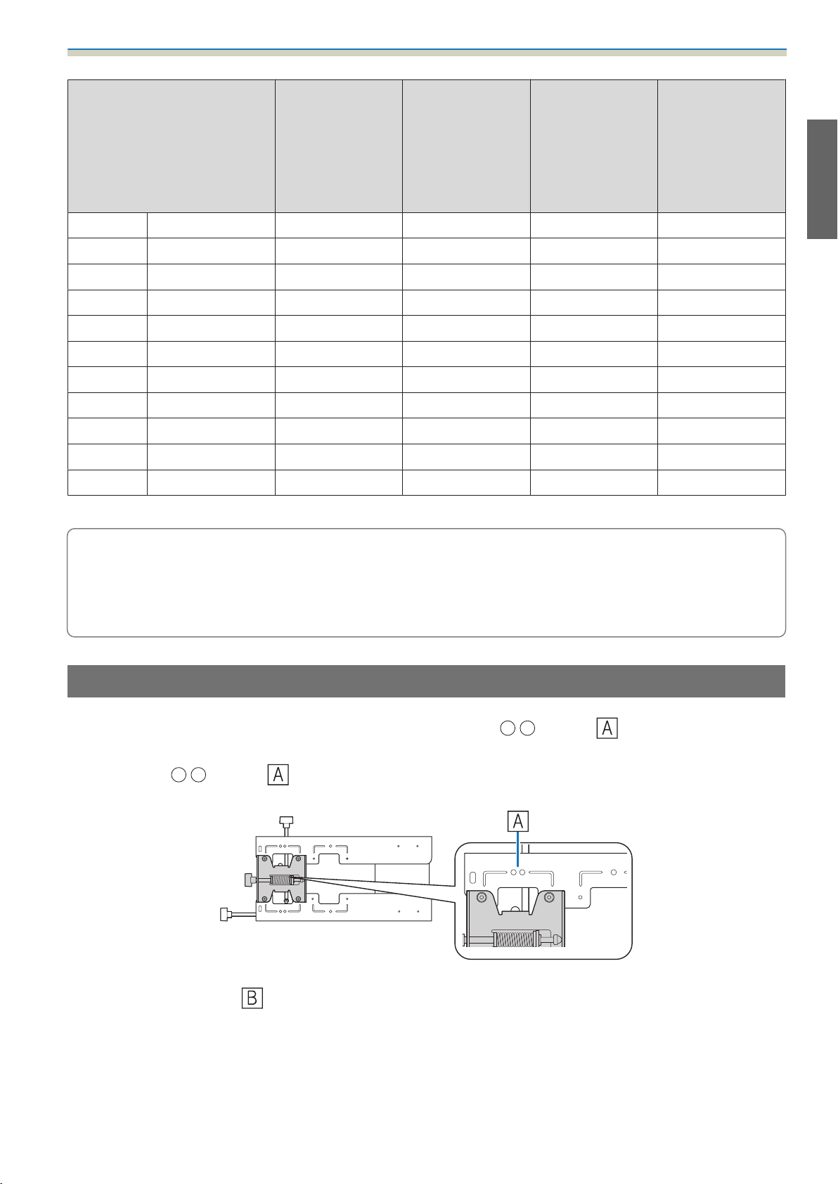
Align the 3-axis adjustment unit with the slide plate's standard position ( )
c
d
( ) indicates the screw holes for the bolts.
Tighten the supplied M4 bolts (x2)
39
Page 42

Installation Guide
Connect the cables to the projector
e
Attach the Wireless LAN unit supplied to the wireless LAN unit's installation section.
•
Connect the power cord last.
•
c
When connecting to the Audio1, Audio Out, and Computer ports, we recommend connecting cables
to the ports in the following order: Audio1, Audio Out, and then Computer.
Adjusting the Projected Image
Follow the procedures below to adjust the projected image.
Adjusting the Projection Position (s p.40)
a
Fine-tuning the Focus (s p.46)
b
Calibrating the Pen (s p.47)
c
Adjusting the Projection Position
•
Do not make adjustments using the projector's Keystone function. Doing so may result in a reduction in image quality.
•
When setting up multiple projectors using the batch setup function, perform this procedure before adjusting the
projected image.
s
"Batch Setup Function" p.75
40
Page 43

Installation Guide
Press the [t] button on the remote control or the control panel to turn on the projector
a
b
Using the Remote Control Using the Control Panel
Caution
While projecting, do not put your face or hands near the air exhaust vent, and do not place objects
that may become warped or damaged by heat near the vent. Hot air from the air exhaust vent could
cause burns, warping, or accidents to occur.
Change the aspect ratio of the projected image (only when necessary)
Project images from a connected device, and then press the [Aspect] button on the remote control.
Each time you press the button, the aspect name is displayed on the screen and the aspect ratio
changes.
Using the Remote Control
c
•
For details on connecting to devices and projecting images, see the Quick Start Guide.
•
The aspect ratio does not change when no images are being projected from the connected
device.
•
You can also change the aspect ratio from Signal - Aspect from the Configuration menu.
s
Projector's User's Guide - Configuration menu
41
Page 44

Installation Guide
Press the following buttons to display the guidance screen
c
•
Using the Remote Control
Press the [Help], and then press [
•
Using the Control Panel
Press the [Help], and then press the [Wide] button.
The guidance screen is displayed.
].
d
Open the air filter cover, and then adjust the focus using the focus lever
After you finish making adjustments, close the air filter cover.
42
Page 45

e
Installation Guide
Loosen the M4 screw (x1) with the hexagon wrench, and then adjust the horizontal roll
with the adjustment dial
Repeat steps 5 to 10 as necessary.
c
f
After you finish making adjustments, tighten the M4 screw that you loosened.
Loosen the M4 screws (x2) with the hexagon wrench, and then adjust the horizontal
rotation with the adjustment dial
After you finish making adjustments, tighten the M4 screws that you loosened.
43
Page 46

Installation Guide
Loosen the M4 screw (x1) with the hexagon wrench, and then adjust the vertical tilt with
the adjustment dial
g
h
After you finish making adjustments, tighten the M4 screw that you loosened.
Loosen the M4 bolts (x2) with the hexagon wrench, and then adjust the horizontal slide
After you finish making adjustments, tighten the M4 bolts that you loosened.
44
Page 47

i
Installation Guide
Loosen the M4 bolts (x2) with the hexagon wrench, and then adjust the forward/backward
slide
j
After you finish making adjustments, tighten the M4 bolts that you loosened.
Loosen the M6 bolt (x1) with the open-ended spanner, and then adjust the vertical slide
Adjust the vertical slide with the hexagonal axis at the top or the bottom.
•
Tightening the hexagonal axis at the top raises the setting plate, and loosening the axis lowers it.
•
Tightening the M8 bolt at the bottom lowers the setting plate, and loosening the bolt raises it.
k
After you finish making adjustments, tighten the M6 bolt that you loosened.
Make sure that all of the bolts that you loosened in steps 5 to 10 are securely tightened
Warning
Tighten all bolts and screws firmly. Otherwise, the product may fall and cause personal injury or
property damage.
45
Page 48

Installation Guide
Press the [Esc] button on the remote control or the control panel to remove the guidance
screen
l
Fine-tuning the Focus
Turn on the projector, and then press the [Menu] button
a
b
Using the Remote Control Using the Control Panel
Select Pattern from Settings
c
Select Test Pattern
When displaying on a 4:3 screen, set Pattern Type to Pattern 5, and then select Pattern Display.
46
Page 49

Adjust the focus to match the focus in the following figure ( )
Installation Guide
d
Open the air filter cover, and then adjust the focus.
s
"Adjusting the Projection Position" p.40
When (
until the (
) is in focus, check the ( ) areas. If any of the ( ) areas are out of focus, adjust the focus
) areas are uniform.
After you finish making adjustments, close the air filter cover.
Press the [Esc] button on the remote control or the control panel to remove the Test Pattern
e
Calibrating the pen
Check that adjusting the projected image is complete before you start calibrating the interactive pen.
s
"Adjusting the Projected Image" p.40
There are two methods available for calibrating the pen; Auto Calibration and Manual Calibration. When
calibrating the pen for the first time after installing the projector, perform Manual Calibration for optimum
calibration.
For the Auto Calibration method, see the projector's User's Guide (on the Document CD-ROM).
Turn on the projector, and then press the [Menu] button
a
Using the Remote Control Using the Control Panel
47
Page 50

Installation Guide
Select Easy Interactive Function from Extended
b
Select Manual Calibration
c
d
Check that the screen is in focus, and then select Yes
A green dot is displayed at the top left of the projection screen.
48
Page 51

Touch the center of the dot with the pen tip button
Installation Guide
e
The dot disappears and moves to the next position.
Make sure you touch the center of the dot. Otherwise, it may not be positioned correctly.
c
49
Page 52

Installation Guide
Repeat step 5 until all of the dots disappear
f
The dot appears at the top left first and then moves towards the bottom right.
When all of the dots disappear, calibration is complete.
•
Check that there are no obstacles between the interactive pen and the Easy Interactive Function
c
receiver (
).
•
If you touch the wrong position, press the [Esc] button on the remote control to return to the
previous dot.
•
To cancel calibration, hold down the [Esc] button for two seconds.
50
Page 53

Attaching the Covers
Attach the wall plate covers
a
Installation Guide
b
Depending on the cable configurations, you may need to cut notches ( ) in the wall plate
c
covers to route the cables. Perform deburring on the cut sides to smooth off any sharp edges.
Make sure you do not damage the cables when routing them through the cut holes.
Also, make sure you operate the cutter safely.
Place the end cap with the concave portion facing up
51
Page 54

Installation Guide
Attach the cable cover to the projector, and then secure it with the screws (x2)
c
Caution
Only a specialist should remove or reinstall the projector, including for maintenance and repairs. See the
projector's User's Guide for instructions on maintenance and repairs.
Warning
•
Never loosen the bolts and nuts after installation. Confirm that the screws have not become loose on a regular
basis. If you find any loose screws, tighten them firmly. Otherwise, the product may fall and cause personal
injury or property damage.
•
Do not hang on this product or hang a heavy object on this product. If this product falls, it could cause death
or personal injury.
52
Page 55

Installing the Control Pad
Installation Procedure
See the following for the Control Pad installation location.
s
"Control Pad installation location" p.5
s
"When installing the Control Pad" p.19
Remove the cable cover
a
Installation Guide
53
Page 56

Installation Guide
Check the installation location, and secure with commercially available M4 screws (20 mm
x4)
b
Secure the Control Pad with commercially available M4 screws (20 mm x4)
Warning
•
Secure so that the screws are not angled on the installation side.
•
Make sure the Control Pad is firmly secured.
•
Do not secure the Control Pad with double-sided sticky tape or magnets.
•
We recommend checking the Control Pad operations before securing it with the screws.
•
c
When installing the Control Pad on a table, attach the rubber feet (x4) supplied to the base of
the Control Pad to prevent it from slipping.
54
Page 57

c
Installation Guide
Supply power using the batteries supplied (x2)
Caution
d
e
f
Before handling the batteries, read the Safety Instructions on the Document CD-ROM.
•
Obtain two AA size manganese or alkaline (recommended) batteries. Do not use any other type
c
Connect the Control Pad ports to the cables connected to the projector as necessary.
See the following for the cable connection methods.
s
"Necessary cables when installing the Control Pad" p.28
Stick the port protection stickers supplied on the ports that are not being used by the
Control Pad.
Attach the cable cover
of battery. Rechargeable batteries cannot be used.
•
When supplying power from the projector, connect the optional Remote control cable set
(ELPKC28) to the projector's Remote port and the Control Pad's Remote port. When supplying
power from the projector, do not install batteries in the Control Pad.
55
Page 58

Installation Guide
Installing the Touch Unit (EB-1430Wi only)
Check that the following procedures have been completed before installing the Touch Unit.
•
Installing the Projector (s p.27)
•
Adjusting the Projected Image (s p.40)
•
Calibrating the Interactive Pen (s p.47)
About installation
•
There are magnets built into the back of the Touch Unit. Normally, the Touch Unit should be installed by attaching
the magnets to the screen.
•
If the magnets cannot be attached to a screen, use commercially available M4 screws (x3).
•
Attach the Touch Unit to the same level surface as the screen surface.
•
Attach the Touch Unit to a flat, smooth, unwarped surface. If there is unevenness on the screen surface of more than
5 mm, the position of your fingers is not detected, and touch operations may not be performed correctly.
Installation Procedure
Install the Touch Unit, and then connect to the projector.
Caution
Only connect the Touch Unit to the EB-1430Wi. Do not connect it to any other projectors or devices.
Turn on the projector, and then press the [Menu] button
a
Using the Remote Control Using the Control Panel
Select Easy Interactive Function from Extended
b
56
Page 59

c
d
Installation Guide
Select Touch Unit Setup
Select Installation Pattern
e
The installation pattern is displayed on the projected image.
Loosen the screw at the bottom of the dial cover using a commercially available No.2 crosshead screwdriver
57
Page 60

Installation Guide
Slide the dial cover down to remove it
f
Remove the markers (x2) from the Touch Unit
g
h
Use the removed markers to perform angle adjustment for laser diffusion after installing the Touch Unit.
Determine the installation position for the Touch Unit
We recommend marking the following installation positions to make installation easier.
(
): Center line of installation pattern. Align with the center line of the Touch Unit ( ).
): 25 mm from the top edge of the projected image. Align with the bottom edge of the Touch Unit.
(
[Unit: mm]
58
Page 61

Secure the Touch Unit
Installation Guide
i
•
Magnetic screens: Place the back of the Touch Unit on the screen surface, and then secure.
Caution
When installing the Touch Unit on a magnetic surface, be careful not to trap your fingers or any
other part of your body between the magnets and the installation surface. Powerful magnets are
used which can cause injury if you trap your fingers.
•
Non-magnetic screens: Attach spacers and secure with M4 screws (x3).
59
Page 62

Installation Guide
Connect the Touch Unit connection cable that is connected to the projector to the TCH
port on the Touch Unit
j
[Unit: mm]
Screw hole cross-section
Angle Adjustment
Adjust the angle of the laser light coming from the Touch Unit so that the Touch Unit can detect the position
of your fingers.
60
Page 63

c
a
Installation Guide
Before adjusting the angle, make sure that interactive pen calibration is complete.
s
"Calibrating the pen" p.47
Select Easy Interactive Function in Extended from the projector's Configuration menu
b
Select Touch Unit Setup
61
Page 64

Installation Guide
Set Power to On
c
The Touch Unit power turns on and the indicator is lit blue.
Warning
Do not look into the projector's projection window or the Touch Unit's laser diffusion ports. This
could cause damage to eyesight due to the powerful laser light emitted.
When Power is set to On, the next time the projector is turned on, the Touch Unit automatically
turns on.
c
62
Page 65

d
Installation Guide
Select Angle Adjustment
The following screen is displayed.
63
Page 66

Installation Guide
Turn the adjustment dials on the Touch Unit counterclockwise until you hear a clicking
sound
e
When you hear a clicking sound coming from the adjustment dial, stop turning, and then press the
[
] button on the remote control. The following screen is displayed.
64
Page 67

Installation Guide
Attach the two markers that you removed from the Touch Unit to the marker positions
f
(
) ( ) on the projection screen
Match the positions so that the crosses ( ) for the markers overlap with the points ( ) for the
(
) ( ).
When pointers ( ) ( ) with the same color as the marker positions are displayed on the left and
right of the projection screen, attach the markers to the projection screen.
•
Magnetic screens: Place the bottom of the markers onto the screen.
•
Non-magnetic screens: Use the supplied tape to secure the markers. Attach the tape so that the either end of
marker does not come loose off the screen.
Correct Incorrect
Do not place anything other than the markers near the projected image during angle
adjustment. If other objects are on the projected image, angle adjustment may not be
c
performed correctly.
65
Page 68

Installation Guide
Turn the adjustment dials on the Touch Unit to move the pointers ( ) ( ) so that they
g
overlap with the target (
When you turn the adjustment dial clockwise, the pointer moves diagonally up towards the center of
the projected image.
) ( ) of the same color on either side
When you turn the adjustment dial counterclockwise, the pointer moves diagonally down away from
the center of the projected image.
When the pointers overlap in the correct position, the colors become solid ( ) ( ).
•
If you hear a clicking sound from the dial, the pointer does not move any further.
•
c
When turning the dials, make sure shadows from your arm or body do not overlap with the
markers.
66
Page 69

h
Installation Guide
When the pointers on the left and right become solid colors ( ) ( ), press the [ ]
button on the remote control
The following screen is displayed.
i
Place the markers at the top marker positions [1] ( ) ( )
When angle adjustment is performed correctly, the upper pointers become solid colors ( ) ( ).
If the upper pointers do not become solid colors ( ) ( ), start again from step 4.
67
Page 70

Installation Guide
Place the markers at the bottom marker positions [2] ( ) ( )
j
When angle adjustment is performed correctly, the bottom pointers become solid colors ( ) ( ).
k
If the bottom pointers do not become solid colors ( ) ( ), start again from step 4.
When you have finished checking, remove the markers, and then press the [ ] button on
the remote control
The following screen is displayed.
68
Page 71

Trace the dots ( ) with your finger
Installation Guide
l
When angle adjustment is performed correctly, the dots you have traced disappear.
Touch operations may not perform correctly if you are wearing artificial nails or nail polish, or
if your fingers are obstructed by bandages and so on.
c
When all of the dots have disappeared, press the [ ] button on the remote control, and then go to
step 14.
If some dots remain as shown in the following figure, check the following points.
•
Remove any obstacles that are around the projection screen. After removing any obstacles, press the [ ] or
] button on the remote control, and then perform step 12 again.
[
•
If the dots still remain after removing obstacles, turn the adjustment dials about a quarter turn
counterclockwise. Next, press the [
again.
•
Go to step 13 if dots still remain even after performing this step, or there are obstacles that cannot be removed
such as whiteboard trays or frames.
] or [ ] button on the remote control, and then perform step 12
69
Page 72

Installation Guide
Stick the infrared deflectors supplied so that the laser is not reflected by the obstacle (only
if there is an obstacle near the projection screen that cannot be moved)
m
Stick the deflectors between the dots and the obstacle. Adjust the number of deflectors according to
the number of dots.
Remove the tape from the back of the infrared deflectors, and stick them on the screen.
n
•
Do not remove an infrared deflector once it has been stuck in place. This can weaken the adhesive
c
After placing the infrared deflectors, press the [ ] or [ ] button on the remote control, and then
perform step 12 again.
If the dots do not disappear even after attaching the infrared deflectors, turn the adjustment dials
about a quarter turn counterclockwise. Next, press the [
and then perform step 12 again.
If the dots do not disappear even after performing the above procedures, contact your local dealer
from the Epson Projector Contact List provided on the Document CD-ROM.
Store the markers in the Touch Unit
strength of the tape.
•
Do not stick tape or place anything on the infrared deflectors. The infrared deflector will not
function correctly.
] or [ ] button on the remote control,
70
Page 73

Attach the labels at the tabs on either side of the Touch Unit
Installation Guide
o
Match the center of the labels with the tabs on the Touch Unit.
If the Touch Unit moves out of position, use the labels to reinstall it at the correct position.
c
Attach the dial cover, and then tighten the screw at the bottom of the dial cover
p
Touch Calibration
Perform touch calibration so that the projector can recognize touch operations precisely.
Press the projector's [Menu] button
a
Using the Remote Control Using the Control Panel
71
Page 74

Installation Guide
Select Easy Interactive Function from Extended
b
Select Touch Unit Setup
c
d
Select Touch Calibration
The focus adjustment message is displayed.
72
Page 75

e
Installation Guide
Check that the screen is in focus, and then select Yes
A dot is displayed at the top left of the projection screen.
Touch the center of the dot with your finger
f
When the dot disappears and moves to the next position, remove your finger.
•
Make sure you touch the center of the dot. Otherwise, it may not be positioned correctly.
c
•
Do not touch with anything else except the tip of your finger.
73
Page 76

Installation Guide
Repeat step 6 until all of the dots disappear
g
When all of the dots disappear, touch calibration is complete.
•
If you touch the wrong position, press the [Esc] button on the remote control or control panel.
c
This returns you to the previous dot. You cannot go back by two dots.
•
To cancel touch calibration, hold down the [Esc] button for two seconds.
•
It may take several seconds after all of the dots have disappeared until touch calibration is
complete.
74
Page 77

Appendix
Batch Setup Function
Once the Configuration menu content has been set for one projector, you can use it to perform batch setup
for multiple projectors (batch setup function). The batch setup function is only for projectors with the same
model number.
Use one of the following methods.
•
Setup using a USB flash drive.
•
Setup using EasyMP Network Updater.
This guide explains how to use a USB flash drive.
•
The following content is not reflected by the batch setup function.
c
•
Network menu settings (except for the Mail menu and the Others menu)
•
Lamp Hours and Status from the Info menu
•
Perform batch setup before adjusting the projected image. Adjustment values for the projected image,
such as Keystone, are reflected by the batch setup function. If batch setup is performed after adjusting
the projected image, the adjustments you made may change.
•
By using the batch setup function, the registered User's Logo is set for the other projectors. Do not
register confidential information and so on as the User's Logo.
Caution
Performing batch setup is the customers responsibility. If batch setup fails due to a power failure,
communication error, and so on, the customer is responsible for any repair costs incurred.
Saving settings to the USB flash drive
•
Use a FAT format USB flash drive.
•
c
a
b
The batch setup function cannot be used by USB flash drives that incorporate security functions. Use
a USB flash drive that does not incorporate security functions.
•
The batch setup function cannot be used by USB card readers or USB hard disks.
Disconnect the power cord from the projector, and check that all of the projector's
indicators have turned off
Connect the USB flash drive to the projector's USB-A port
•
Do not connect a USB flash drive to the port.
•
c
Connect the USB flash drive directly to the projector. If the USB flash drive is connected to the
projector through a USB hub, the settings may not be saved correctly.
•
Connect an empty USB flash drive. If the USB flash drive contains data other than the batch setup
file, the settings may not be saved correctly.
•
If you have saved a batch setup file from another projector to the USB flash drive, delete the file
or change the file name. The batch setup function cannot overwrite a batch setup file.
•
The file name for the batch setup file is PJCONFDATA.bin. If you need to change the file name,
add text after PJCONFDATA. If you change the PJCONFDATA section of the file name, the
projector may not be able to recognize the file correctly.
•
You can only use single-byte characters for the file name.
75
Page 78

Appendix
While holding down the [Esc] button on the remote control or the control panel, connect
the power cord to the projector
c
The status indicator and the power indicator turn blue, and the lamp indicator and the temperature
indicator turn orange.
When all of the projector's indicators turn on, release the [Esc] button.
When all of the indicators start flashing, the batch setup file is being written.
•
•
Caution
Do not disconnect the power cord from the projector while the file is being written. If the power cord
is disconnected, the projector may not start correctly.
Do not disconnect the USB flash drive from the projector while the file is being written. If the USB flash
drive is disconnected, the projector may not start correctly.
When writing completes normally, the projector turns off, and only the power indicator is lit blue.
When the power turns off, remove the USB flash drive.
Reflecting saved settings to other projectors
Disconnect the power cord from the projector, and check that all of the projector's
indicators have turned off
a
Connect the USB flash drive containing the saved batch setup file to the projector's USB-A
port
b
•
Do not connect a USB flash drive to the port.
•
c
When the USB flash drive contains 1 to 3 types of batch setup files, the file is reflected to the
projector with the same model number. If there are multiple files for a projector with the same
model number, the settings may not be reflected correctly.
•
When there are four or more types of batch setup files on the USB flash drive, the settings may
not be reflected correctly.
•
Do not store any data except for the batch setup file on the USB flash drive. If the USB flash drive
contains data other than the batch setup file, the settings may not be reflected correctly.
76
Page 79

c
Appendix
While holding down the [Menu] button on the remote control or the control panel, connect
the power cord to the projector
The status indicator and the power indicator turn blue, and the lamp indicator and the temperature
indicator turn orange.
When all of the projector's indicators turn on, release the [Menu] button. The indicators turn on for
approximately 75 seconds.
When all of the indicators start flashing, the settings are being written.
Caution
•
Do not disconnect the power cord from the projector while the settings are being written. If the power
cord is disconnected, the projector may not start correctly.
•
Do not disconnect the USB flash drive from the projector while the settings are being written. If the
USB flash drive is disconnected, the projector may not start correctly.
When writing completes normally, the projector turns off, and only the power indicator is lit blue.
When the power turns off, remove the USB flash drive.
When Setup Fails
Check Remedy
Are the lamp indicator and the tempera‐
ture indicator flashing orange quickly?
The batch setup file may be corrupt, or the USB flash drive may not
be connected correctly. Disconnect the USB flash drive, unplug and
then plug in the projector's power cord, and then try again.
77
Page 80

Appendix
Check Remedy
Are the power indicator and the status in‐
dicator flashing blue quickly, and the lamp
indicator and the temperature indicator
flashing orange quickly?
Writing the settings may have failed and an error may have occurred
in the projector's firmware. Stop using the projector, remove the
power plug from the electrical outlet, and contact your local dealer
or the nearest address provided in the Epson Projector Contact List.
78
Page 81

Appendix
Using the Interactive Function when Multiple
Projectors are Installed
When using the interactive pen in the same room as multiple projectors, infrared interference may cause pen
operations to become unstable. Interactive pen operations are stabilized by linking the projectors using
cables.
By using the optional Remote control cable set (ELPKC28), you can connect the SYNC ports on the projectors
in series. After connecting the ports, set Extended - Easy Interactive Function - Advanced - Sync of
Projectors to Wired from the Configuration menu.
For details, see the projector's User's Guide (on the Document CD-ROM).
•
The SYNC port has an IN and OUT socket. When you connect one end of the cable to an IN socket,
c
connect the other end to an OUT socket.
•
When connecting three or more projectors, you do not need to connect the first projector to the last
projector.
79
Page 82

Appendix
Attaching a Security Cable
A commercially available theft-prevention wire lock can be attached to this product.
Pass the wire for the theft-prevention wire lock through the security cable installation points on the projector
and the setting plate. See the user's guide supplied with the wire lock for locking instructions.
The security slot on this product is compatible with the Microsaver Security System manufactured by
Kensington. See the following for more details on the Microsaver Security System.
http://www.kensington.com/
Projector Touch Unit (EB-1430Wi only)
80
Page 83

Appendix
General Notice
OS X is a trademark of Apple Inc.
Microsoft and Windows are trademarks or registered trademarks of Microsoft Corporation in the United States
and/or other countries.
©SEIKO EPSON CORPORATION 2014. All rights reserved.
Indication of the manufacturer and the importer in accordance with requirements of directive 2011/65/
EU (RoHS)
Manufacturer: SEIKO EPSON CORPORATION
Address: 3-5, Owa 3-chome, Suwa-shi, Nagano-ken 392-8502 Japan
Telephone: 81-266-52-3131
Importer: SEIKO EUROPE B.V.
Address: Azië building, Atlas ArenA, Hoogoorddreef 5, 1101 BA Amsterdam
Zuidoost The Netherlands
Telephone: 31-20-314-5000
81
Page 84

Guide d’installation
Page 85

Page 86

Utiliser le produit de façon sûre
Consignes de sécurité
Pour votre sécurité, veuillez lire toutes les consignes contenues dans ce guide avant d’utiliser ce produit. Une
manipulation incorrecte ne respectant pas ces consignes pourrait endommager ce produit ou provoquer des
blessures corporelles ou des dommages matériels. Conservez ce guide d’installation à portée de main pour
pouvoir vous y reporter ultérieurement.
Lisez le Guide de l’utilisateur et les Consignes de sécurité de votre projecteur et suivez les instructions figurant
dans ces documents.
Indications de sécurité
La documentation et ce produit utilisent des symboles graphiques pour présenter l'utilisation sûre de ce
produit.
Les indications et leur signification sont les suivantes. Assurez-vous de bien les comprendre avant de lire le
guide.
Symbole Explication
Avertisse‐
ment
Attention
Ce symbole signale des informations qui, si elles sont ignorées, peuvent provoquer des bles‐
sures, voire la mort, en raison d’une manipulation incorrecte.
Ce symbole indique des informations qui, si elles sont ignorées, peuvent provoquer des bles‐
sures ou des dommages physiques, en raison d’une manipulation incorrecte.
Explication des symboles
Symboles Explication
Symbole indiquant une action à ne pas faire
Symbole indiquant une action à faire
Symbole signalant des informations connexes ou utiles
c
Consignes de sécurité pour l’installation
Avertissement
La plaque d'installation sert exclusivement à monter le projecteur sur un mur. Si un équi‐
pement autre qu’un projecteur est installé, son poids peut endommager le support.
Si ce produit tombe, il pourrait causer la mort ou des blessures personnelles.
Les travaux d’installation (fixation murale) doivent être effectués par des spécialistes dis‐
posant des compétences techniques et du savoir-faire appropriés. Une installation incom‐
plète ou incorrecte pourrait entraîner la chute de produit et provoquer des blessures ou
des dommages matériels.
Suivez les instructions du présent guide pour installer ce produit.
En cas de non-respect des instructions, ce produit peut tomber et provoquer des blessures corpo‐
relles ou un accident.
1
Page 87

Utiliser le produit de façon sûre
Avertissement
Manipulez le cordon secteur avec précaution.
Une manipulation incorrecte peut provoquer un incendie ou une électrocution. Prenez les pré‐
cautions suivantes en le manipulant :
•
Ne saisissez pas la fiche secteur avec des mains humides.
•
N’utilisez pas un cordon secteur endommagé ou modifié.
•
Ne tirez pas exagérément sur le cordon lorsque vous le faites passer à travers la plaque d’installation.
N’installez pas la plaque d’installation à un endroit où elle peut être soumise à des vibrations
ou des chocs.
Ceci pourrait endommager le produit ou la surface de montage. Si ce produit tombe, il pourrait
causer la mort ou des blessures personnelles.
Installez la plaque d’installation de sorte qu’elle puisse supporter son poids ainsi que celui
du projecteur et résister à toute vibration horizontale. Utilisez des écrous et des boulons
M10.
Les écrous et les boulons de taille inférieure à M10 risquent de causer la chute de la plaque. Epson
n'accepte aucune responsabilité pour tout dommage ou toute blessure dus à une solidité du mur
insuffisante ou une installation inappropriée.
L’installation doit être exécutée par au moins deux techniciens qualifiés. Si vous devez
desserrer des vis pendant l’installation, veillez à ne pas provoquer la chute de ce produit.
Si ce produit tombe, il pourrait causer la mort ou des blessures personnelles.
Lors du montage de ce produit sur un mur, le mur doit être assez résistant pour pouvoir
tenir le projecteur, la plaque d'installation, le Control Pad et l'unité tactile (EB-1430Wi uni‐
quement).
Ce produit doit être installé sur un mur en béton. Le poids combiné maximal du projecteur, de la
plaque d'installation et du Control Pad est d'environ 14 kg (câbles non compris). Lorsque l'unité
tactile (EB-1430Wi uniquement) est installée, le poids maximal est d'environ 14,5 kg (hors câbles).
Vérifiez la résistance du mur avant de monter ce produit dessus. Si la solidité du mur est insuffisante,
renforcez le mur avant de procéder à l’installation.
Contrôlez régulièrement la plaque d’installation pour vérifier qu’aucune de ses pièces n’est
endommagée ou que des vis ne sont pas desserrées.
Si des pièces sont endommagées, cessez immédiatement d’utiliser la plaque d’installation. Si ce
produit tombe, il pourrait causer la mort ou des blessures personnelles.
Ne démontez et ne remontez pas ce produit.
Il existe plusieurs sections à haute tension dans le produit pouvant causer des incendies, décharges
électriques ou accidents.
Ne vous suspendez pas au produit et n'y suspendez pas un objet lourd.
Si ce produit tombe, il pourrait causer la mort ou des blessures personnelles.
N’utilisez pas d’adhésifs, ni d’huiles ou lubrifiants pour installer ou régler la plaque d’in‐
stallation.
Si vous utilisez des adhésifs pour empêcher les vis de se desserrer ou si vous utilisez des lubrifiants
ou des huiles sur la plaque coulissante de fixation du projecteur, le boîtier risque de se détériorer,
au risque de provoquer la chute du projecteur et des blessures corporelles ou des dommages
matériels.
Serrez fermement toutes les vis après tout réglage.
Sinon, le produit peut tomber et provoquer des blessures corporelles ou des dommages matériels.
2
Page 88

Utiliser le produit de façon sûre
Avertissement
Ne desserrez jamais les écrous et les boulons après l’installation.
Vérifiez régulièrement que les vis ne se sont pas desserrées. Si vous constatez le moindre jeu,
resserrez fermement les vis concernées. Sinon, le produit peut tomber et provoquer des blessures
corporelles ou des dommages matériels.
Acheminez les câbles afin qu'ils n'interfèrent pas avec les écrous et boulons.
Une manipulation incorrecte des câbles peut provoquer un incendie ou une électrocution.
Lorsque vous allumez le projecteur, ne regardez pas la fenêtre de projection.
Ceci pourrait endommager votre vue en raison de la puissante lumière émise. Faites particulière‐
ment attention en présence d'enfants. Lorsque vous allumez le projecteur à distance avec la télé‐
commande, assurez-vous que personne ne regarde la fenêtre de projection.
Lorsque vous utilisez le projecteur, ne placez aucun objet et ne placez pas votre main à
proximité de la fenêtre de projection.
Cette zone est dangereuse car elle atteint des températures élevées en raison de la lumière de
projection concentrée.
Ne couvrez pas les entrées ou sorties d'air du projecteur. Si les orifices de ventilation sont
couverts, la température interne pourrait augmenter et causer un incendie.
Évitez les emplacements sujets à de hautes températures, comme à proximité de radiateurs, et
laissez un espace d'au moins 20 cm entre le mur et l'orifice de ventilation.
N'utilisez pas le projecteur à un emplacement exposé à des combustibles ou gaz explosifs.
Le projecteur peut prendre feu en raison de la température élevée de la lampe du projecteur.
Si des anormalités surviennent avec ce produit, débranchez immédiatement les câbles du
produit, puis contactez votre revendeur local ou le centre d'appel Epson le plus proche.
Continuer à utiliser ce produit dans des conditions anormales peut causer un incendie, un choc
électrique ou des dommages oculaires.
Attention
N’installez pas ce produit dans un endroit qui excède la plage de température de fonc‐
tionnement du modèle de projecteur.
Un tel environnement peut endommager le projecteur.
Installez ce produit dans un endroit à l’abri de la poussière et de l’humidité pour que l’ob‐
jectif et les éléments optiques internes ne se salissent pas.
N'exercez pas une force excessive pendant le réglage du produit.
Le produit peut être endommagé et provoquer des blessures corporelles.
3
Page 89

Utiliser le produit de façon sûre
Remarques sur la manipulation de l'unité tactile (EB-1430Wi uniquement)
Avertissement
Ne démontez et ne remontez pas l'unité tactile.
L'unité tactile comprend un produit laser haute puissance pouvant causer des incendies, décharges
électriques ou accidents.
Suivez les instructions de ce guide pour configurer et utiliser l'unité tactile.
Si l'unité tactile n'est pas configurée et utilisée correctement, elle pourrait causer des dégâts ocu‐
laires en raison de la lumière émise par le laser.
N'appliquez pas des appareils optiques comme des télescopes ou des loupes à la lumière
du laser diffusée par l'unité tactile.
L'utiliser dans de telles conditions peut avoir un effet négatif sur le corps humain. Ceci pourrait
également causer un incendie ou un accident.
Ne regardez pas dans les ports de diffusion du laser de l'unité tactile.
Ceci pourrait endommager votre vue en raison de la puissante lumière laser émise. Faites particu‐
lièrement attention en présence d'enfants.
Ne regardez pas la lumière du laser avec des appareils comme des loupes à moins de 70 mm
des ports de diffusion laser de l'unité tactile.
Ceci pourrait causer des dégâts oculaires.
Ne branchez l'unité tactile que sur le EB-1430Wi. Ne le branchez pas sur d'autres projecteurs
ou appareils.
L'appareil pourrait avoir un dysfonctionnement, ou la lumière du laser pourrait sortir de sa zone
restreinte.
Ne vous approchez pas de l'unité tactile si vous utilisez un équipement médical, par exem‐
ple un pacemaker. De plus, lors de l'utilisation de l'unité tactile, veuillez à ce que personne
n'utilise un équipement médical, par exemple un pacemaker, dans les environs.
Un aimant puissant génère des interférences électromagnétiques dans l'appareil, ce qui peut cau‐
ser des dysfonctionnements des équipements médicaux.
Attention
Ne vous approchez pas de l'unité tactile avec des supports de stockage magnétiques com‐
me des cartes magnétiques ou des appareils électroniques de précision, comme des or‐
dinateurs, montres numériques ou téléphones mobiles.
Un aimant puissant présent dans l'unité pourrait endommager les données ou causer un dysfonc‐
tionnement.
À propos de ce Guide d’installation
Le présent guide décrit comment monter le projecteur à courte distance EB-1430Wi/EB-1420Wi sur un mur.
Il explique également comment installer le Control Pad et l'unité tactile (EB-1430Wi uniquement) après
montage sur un mur.
4
Page 90

Utiliser le produit de façon sûre
Choisir un emplacement d'installation
Emplacement d'installation du projecteur
•
Préparez à l’avance le câblage de l’alimentation électrique de l’emplacement d’installation de la plaque d’installation.
•
Éloignez le projecteur des autres appareils électriques, notamment des éclairages fluorescents ou des climatiseurs.
Certains types d’éclairages fluorescents risquent d’interférer avec la télécommande du projecteur.
•
Nous vous recommandons d’utiliser un câble de connexion d’une longueur inférieure à 20 mètres afin de réduire
l’effet de parasites.
•
Nous recommandons l’utilisation d’écrans à manche ou à carte.
•
Vérifiez que le projecteur est installé dans les conditions suivantes.
•
L'image projetée est une forme rectangulaire sans distorsion.
•
Le projecteur est incliné à un angle d'au plus ±3° à la verticale et à l'horizontale par rapport à l'écran.
•
Lors de l'utilisation de la fonction interactive (Easy Interactive Function), installez l'appareil de sorte que l'image
projetée soit à portée.
•
N'installez pas le projecteur ou l'écran à un endroit exposé directement à la lumière du soleil. Si le projecteur ou l'écran
sont directement exposés à la lumière du soleil, la fonction interactive pourrait ne pas fonctionner correctement.
Emplacement d'installation du Control Pad
Lorsque vous alimentez le Control Pad avec des piles, vérifiez que l'emplacement d'installation réponde aux
exigences suivantes.
•
Installez le Control Pad sur la même surface que l'écran de projection.
Si l'écran de projection et le point d'installation du Control Pad ne sont pas au même niveau, installez le Control
Pad à environ 20 cm du bord de l'écran.
•
Assurez-vous qu'il n'existe aucun objet bloquant le signal entre le Control Pad et le projecteur (hors unité tactile).
Dans les cas suivants, utilisez le Jeu de câbles de télécommande (ELPKC28) pour alimenter le Control Pad
depuis le projecteur.
•
Lorsque les conditions mentionnées ci-dessus ne sont pas remplies.
•
Lorsque l'écran de projection et le point d'installation du Control Pad ne sont pas au même niveau et si la différence
de hauteur est supérieure à 5 cm
•
Lorsque le projecteur est placé sur une table et projette vers l'écran.
•
Lorsque plusieurs projecteurs sont utilisés.
Emplacement d'installation de l'unité tactile (EB-1430Wi uniquement)
•
Lorsque vous utilisez l'unité tactile, installez le projecteur avec l'une des méthodes suivantes. L'unité tactile ne peut
pas être utilisée si vous employez une autre méthode d'installation.
•
Montez le projecteur sur un mur ou suspendez-le depuis un plafond, et projetez les images vers l'avant de l'écran.
•
Installez verticalement sur une table et projetez vers l'avant de la table. (Lors de l'installation à la verticale sur une
table, vous devez disposer de l'Interactive Table Mount en option (ELPMB29).)
•
Avant d'installer l'unité tactile, veillez à ce que l'emplacement d'installation réponde aux conditions suivantes.
•
L'unité tactile peut être fixée avec des aimants ou des vis.
•
Une surface plate, douce et régulière sur la surface de l'écran de plus de 5 mm.
5
Page 91

Utiliser le produit de façon sûre
•
Lors de l'installation d'un tableau blanc, installez l'unité tactile à l'intérieur du cadre du tableau blanc.
Position d'installation correcte Position d'installation incorrecte
•
Lors de l'installation de l'unité tactile, vérifiez l'absence d'obstacles, par exemples des câbles, et des objets
protubérants comme des plateaux de tableau blanc, supports ou cadres épais dans les zones ombrées de l'illustration
suivante. L'unité tactile ne fonctionnera pas correctement.
[Unité : mm]
6
Page 92

Table des matières
Utiliser le produit de façon sûre
Consignes de sécurité ................. 1
Indications de sécurité....................1
Explication des symboles..................1
Consignes de sécurité pour l’installation....... 1
Remarques sur la manipulation de l'unité tactile
(EB-1430Wi uniquement)..................4
À propos de ce Guide d’installation ...........4
Choisir un emplacement d'installation
....................................... 5
Emplacement d'installation du projecteur...... 5
Emplacement d'installation du Control Pad . . . . . 5
Emplacement d'installation de l'unité tactile
(EB-1430Wi uniquement)..................5
Guide d’installation
Procédé d'installation ................. 9
Contenu de l’emballage .............. 10
Plaque d’installation .....................10
Control Pad........................... 11
Unité tactile (EB-1430Wi uniquement) . . . . . . . . 11
Spécifications ....................... 12
Plaque d’installation .....................12
Plaque murale .......................12
Plage de réglage du coulissement vertical
.................................. 13
Plage de réglage du coulissement horizontal
.................................. 13
Plage de réglage du coulissement vers
l’avant/l’arrière......................14
Control Pad........................... 14
Lors de l'installation de l'unité tactile
(EB-1430Wi uniquement)...............17
Lors de l'installation du Control Pad........ 19
Lorsque l'image projetée est inférieure à
75 pouces ............................ 20
Image projetée 16:10 ..................21
Image projetée 16:9 ................... 21
Image projetée 4:3.................... 22
Lorsque l'image projetée est supérieure à
75 pouces ............................ 23
Image projetée 16:10 ..................24
Image projetée 16:9 ................... 24
Image projetée 4:3.................... 25
Installer la plaque d'installation ....... 27
Connexion des appareils .................. 27
Câbles nécessaires ....................27
Procédure d’installation..................30
Désassembler les pièces................ 30
Assembler les pièces ..................30
Installer la plaque murale sur le mur.......32
Déterminez la distance de projection, puis
passez les câbles à travers la plaque
d'installation........................34
Fixer la plaque d’installation à la plaque
murale............................36
Fixer le projecteur à la plaque d’installation
.................................. 38
Ajuster l'image projetée ..................40
Ajuster la position de projection.......... 40
Affiner la mise au point .................46
Calibrer le stylet......................47
Fixation des caches..................... 51
Control Pad (dimensions externes/poids) . . . . 14
Trous d'acheminement des câbles .........15
Unité tactile (EB-1430Wi uniquement) . . . . . . . . 15
Unité tactile (dimensions externes/poids)
.................................. 15
Étiquettes jointes .....................16
Port de diffusion du laser...............16
Tableau de distance de projection . . . . . 17
Illustrations des dimensions de l'installation ....17
Installer le Control Pad ............... 53
Procédure d’installation..................53
Installation de l'unité tactile
(EB-1430Wi uniquement) ............. 56
Procédure d’installation..................56
Réglage de l'angle...................... 60
Calibrage tactile ........................ 71
Annexe
Fonction de configuration en lot ...... 75
7
Page 93

Table des matières
Enregistrer les réglages sur la clé USB........75
Refléter les réglages enregistrés sur d'autres
projecteurs........................... 77
Lorsque la configuration échoue ............78
Utiliser la fonction interactive lorsque
plusieurs projecteurs sont installés
...................................... 80
Fixation d’un câble de sécurité ........ 81
Remarque générale .................. 82
8
Page 94

Guide d’installation
Procédé d'installation
Suivez les procédures ci-dessous pour monter le projecteur sur un mur.
Installer la plaque d'installation et le projecteur (s p.27)
a
Ajuster l'image projetée (s p.40)
b
Calibrer le stylet interactif (s p.47)
c
Installer le Control Pad (s p.53)
d
Lors de l'installation de l'unité tactile, terminez d'abord l'installation du projecteur puis suivez les procédures
ci-dessous (EB-1430Wi uniquement).
Installer l'unité tactile (s p.56)
a
Ajuster l'angle de diffusion du laser (s p.60)
b
Effectuer le calibrage tactile (s p.71)
c
9
Page 95

Guide d’installation
Contenu de l’emballage
Plaque d’installation
Les éléments fournis suivants sont nécessaires pour monter le projecteur sur un mur. Confirmez que vous
disposez de tous les éléments avant de commencer.
Plaque d’installation Axe hexagonal Plaque murale
Cache de la plaque murale Dispositif de réglage à 3 axes
*La plaque coulissante (
lors de l'expédition.
Capuchon de protection Clé à six pans (pour M4) Clé plate
Forme Nom
) est fixée
Quan‐
(pour l’installation de la plaque mu‐
6 mm (pour l'axe hexagonal)
Fiche modèle
rale)
13 mm (pour M8 et M6),
Application
tité
Boulon à tête cylindrique à six pans M4 x
12 mm avec rondelle/rondelle élastique
6 Pour l’assemblage de la plaque murale
4 Pour l’installation du dispositif de réglage à
3 axes/du bras
4 Pour l’installation de la plaque coulissante/du
projecteur
2 Pour l’installation de la plaque coulissante/du
dispositif de réglage à 3 axes (fixés lors de la
livraison)
Boulon à épaulement à six pans M6 x
20 mm avec rondelle/rondelle élastique
Vis à épaulement à tête à empreinte cru‐
ciforme M6 x 20 mm avec rondelle plasti‐
que
1 Pour installation de la plaque d'installation/
murale
3
10
Page 96

Guide d’installation
•
Utilisez les boulons ou vis fournis avec ce produit pour l'installer, comme décrit dans le présent guide. Ne leur
substituez pas un autre type de boulons.
•
Vous devez aussi utiliser des pattes de fixation M10 x 60 mm disponibles en magasin (au moins 3) pour fixer la plaque
murale au mur.
•
Rassemblez les outils et les éléments nécessaires avant de commencer l’installation.
Control Pad
Les produits fournis suivants sont nécessaires lors de l'installation du Control Pad. Vérifiez que vous disposez
de tous les éléments avant de commencer.
Piles AA (x2) Pieds en caout‐
chouc
Unité principale du Control Pad
Étiquettes de pro‐
tection des ports
Lors de l'installation du Control Pad sur un mur ou autre, préparez des vis M4 disponibles dans le commerce
(20 mm x 4).
Unité tactile (EB-1430Wi uniquement)
Les produits fournis suivants sont nécessaires lors de l'installation de l'unité tactile. Vérifiez que vous disposez
de tous les éléments avant de commencer.
Unité tactile/Marqueurs x2 (joints à l'unité tactile) Câble de connexion à l'unité tactile
Espaceur pour trou de
vis x3
Étiquette x4 Bande (environ 6 cm) pour fi‐
xer le marqueur x12
Déflecteur infrarouge
(environ 28,5 cm) x 8
Lors de l'installation de l'unité tactile sur une surface non magnétique, préparez trois vis M4.
11
Page 97

Guide d’installation
Spécifications
Plaque d’installation
Élément Spécification Remarque Page de ré‐
Poids de la plaque d'installation Environ 8,1 kg Plaque d’installation (3,0 kg), dispositif de ré‐
glage à 3 axes (1,2 kg), plaque coulissante
(0,8 kg), plaque murale (2,7 kg), cache de la
plaque murale et capuchon de protection
(0,4 kg)
Capacité de charge maximale 7 kg
férence
Plage de réglage du coulisse‐
ment vers l’avant/l’arrière
Plage de réglage du coulisse‐
ment vertical
Plage de réglage du roulis hori‐
zontal
Plage de réglage de la rotation
horizontale
Plage de réglage de l’inclinai‐
son verticale
Plage de réglage du coulisse‐
ment horizontal
Plaque murale
0 à 360 mm Plage de réglage du coulissement du bras : 0
à 273 mm
Réglage pour la position d’installation du dis‐
positif de réglage à 3 axes : 87 mm
±38 mm Voir l'illustra‐
±3° Réglages précis possibles avec la molette de
réglage
±8° Réglages précis possibles avec la molette de
réglage
±3° Réglages précis possibles avec la molette de
réglage
±45 mm Voir l'illustra‐
Voir l'illustra‐
tion ci-des‐
sous
tion ci-des‐
sous
s
p.40
s
p.40
s
p.40
tion ci-des‐
sous
L'illustration suivante présente trois plaques murales reliées pour former une plaque (séparées lors de la
livraison).
[Unité : mm]
12
Page 98

*
Décalage pour la position du centre de l’image projetée et du centre de la plaque murale
Guide d’installation
Trous d'acheminement des câbles
Lorsque vous acheminez des câbles pour vous connecter au projecteur à travers un mur, utilisez les positions
) et ( ) de l'illustration suivante comme trous d'acheminement des câbles.
(
Plage de réglage du coulissement vertical
[Unité : mm]
Plage de réglage du coulissement horizontal
13
[Unité : mm]
Page 99

Guide d’installation
Plage de réglage du coulissement vers l’avant/l’arrière
Plage de réglage du coulissement du bras
[Unité : mm]
Plage de réglage à partir de la position d’installation du dispositif de réglage à 3 axes
Control Pad
Control Pad (dimensions externes/poids)
[Unité : mm]
14
[Unité : mm]
Page 100

•
Poids : environ 240 g (sans les piles et les pieds en caoutchouc)
•
Température d'utilisation : 0 à +50°C (sans condensation)
•
Température d'utilisation : -20 à +60°C (sans condensation)
Guide d’installation
Trous d'acheminement des câbles
Lorsque vous acheminez des câbles à travers un mur, utilisez la position ( ) de l'illustration suivante comme
trou d'acheminement des câbles. Sinon, retirez le couvercle des câbles (
d'ici. Faites passer le câble de l'imprimante le long de la rainure à l'arrière du Control Pad.
) et acheminez les câbles à partir
Unité tactile (EB-1430Wi uniquement)
Unité tactile (dimensions externes/poids)
[Unité : mm]
15
 Loading...