

Page 1
SERVICE MANUAL
A3 Color Laser Printer
EPSON AcuLaser C9200N
Page 2
Manual Configuration
Symbols Used in this Manual
Indicates an operating or maintenance procedure, practice or
C H E C K
P O I N T
A D J U S T M E N T
R E Q U I R E D
condition that, if not strictly observed, would result in injury or loss
of life.
This manual consists of the following seven chapters:
CHAPTER 1 PRODUCT DESCRIPTIONS
Describes the main features, basic specifications, consumable produ cts,
periodic replacement parts, and controller interface of the product.
CHAPTER 2 OPERATING PRINCIPLES
Describes each mechanism configurations and explains fundamental
operating principle of major components including the control system.
CHAPTER 3 TROUBLESHOOTING
Describes the troubleshooting procedures that can help you diagnose and
resolve problems. The problems are sorted by displayed error codes and
phenomena of abnormal image output.
CHAPTER 4 DISASSEMBLY/ASSEMBLY
Describes the step-by-step procedures for disassembling and assembling
of the product.
CHAPTER 5 ADJUSTMENT
Describes the settings and the adjustments to be performed during the
maintenance work.
CHAPTER 6 MAINTENANCE
Describes preventive maintenance procedures.
CHAPTER 7 APPENDIX
Provides the additional information such as panel operations, connector
pin layouts, parts list, and exploded diagrams for reference.
Indicates an operating or maintenance procedure, practice or
condition that, if not strictly observed, could result in injury or loss
of life.
Indicates an operating or maintenance procedure, practice or
condition that, if not strictly observed, could result in personal
injury or may cause damage to, or destruction of equipment.
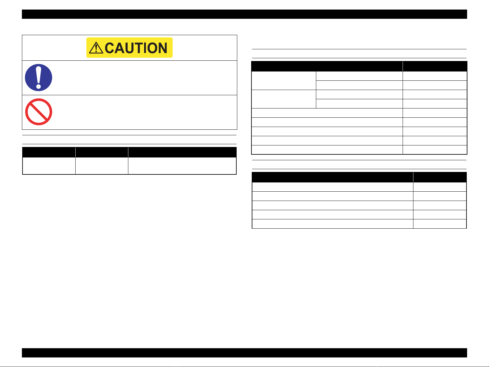
Indicates a prohibited action during maintenance work.
Indicates a mandatory action during maintenance work.
Indicates an operating or maintenance procedure, practice or
condition that is necessary to accomplish a task efficiently .
Provides addi tional information that is related to a specific
subject, or comment on the results achieved through a previous
action.
Indicates a product reassembly procedure, practice or condition
that must be executed in accordance with the specified standards to
maintain the product’s quality.
Various symbols are used throughout this manual either to provide additional
information on a specific topic or to warn of possible danger present during a
procedure or an action. Be sure to read and understand the information with these
symbols.
Indicates an operating or maintenance procedure, practice or
condition that must be executed in accordance with the specified
standards to maintain the product’s quality.
Confidential
Page 3
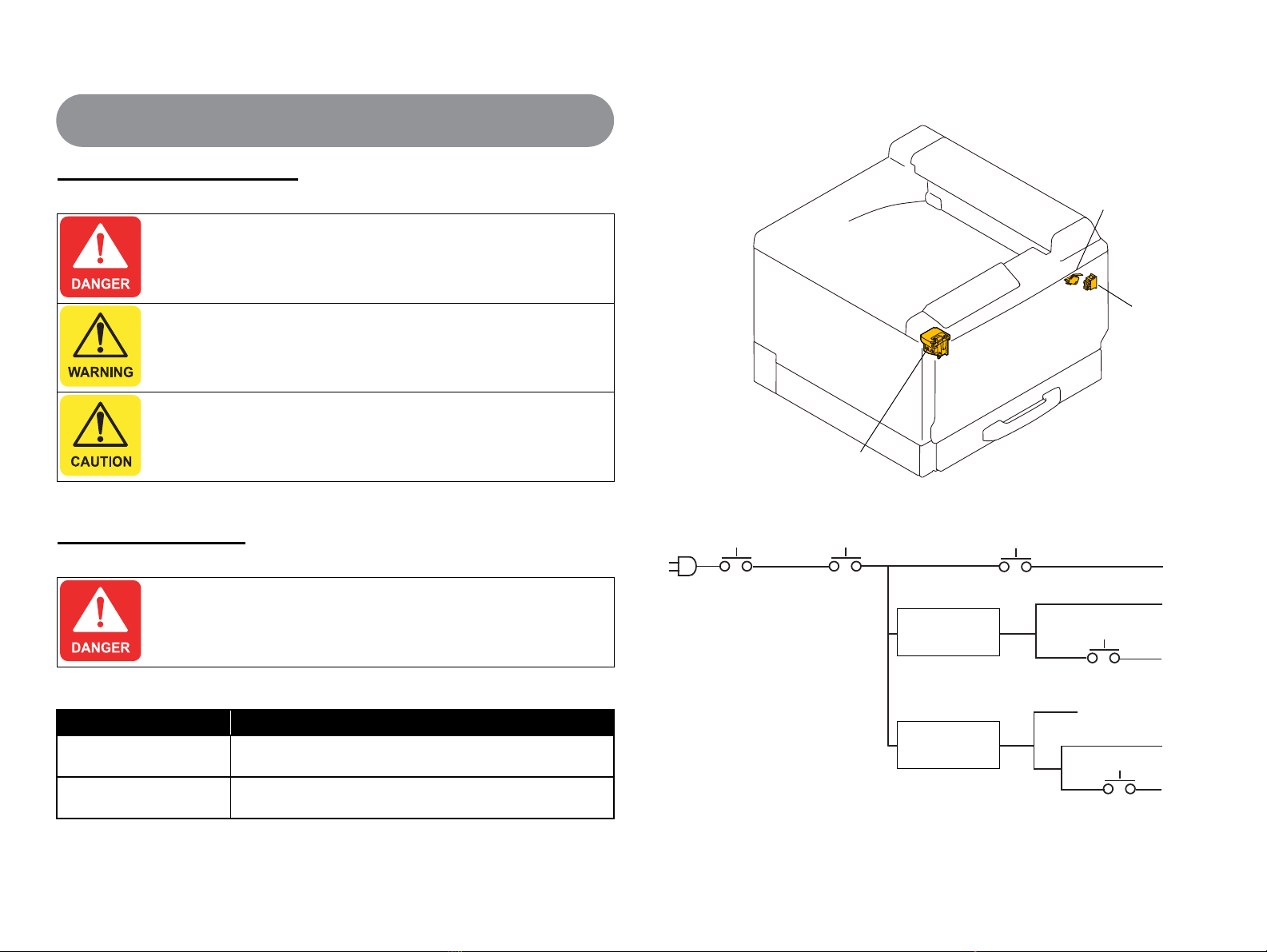
Safety-related Symbols
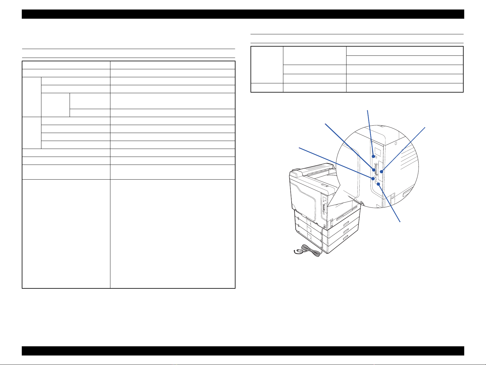
Safety
Right Door SW
Front Door SW
Front Door SW
Main Power Switch Sleep Relay Heater Relay
1
2
3
Front Door SW
/Right Door SW
Main DC Power
Supply
Sub DC Power
Supply
24V
3.3V
5V
Power supply to board
Front Door SW
4
5
Indicates an operating or maintenance procedure, practice or
condition that, if not strictly observed, would result in injury or loss
of life.
Indicates an operating or maintenance procedure, practice or
condition that, if not strictly observed, could result in injury or loss
of life.
Indicates an operating or maintenance procedure, practice or
condition that, if not strictly observed, could result in personal
injury or may cause damage to, or destruction of equipment.
Safety Equipment
Location of Safety Equipment
Safety System Wiring Schematic
Never deactivate the safety equipment installed on the product for
any reason whatsoever. (e.g. Making a connection circuit bypasses
the safety equipment.)
List of Safety Equipment
Name Function/Purpose
Interlock switch (Front Door
SW/Right Door SW)
Interlock switch (Front Door
SW)
Shuts off 24 V DC power line when the Front Door or Right Door
is opened.
Shuts off 5V/3.3V DC power line when the Front Door is opened.
4039T2C133AA
Confidential
Page 4

Laser Beam
Laser Openings
Laser Opening Location
Handling Precautions
Disassembling and adjustment procedures not specified herein
may result in hazardous radiation exposure.
Do not d isassemb le or at tempt to adjust the PH unit for any
reason whatsoever. When the PH unit malfunctions, replace it
with a new one.
Confidential
Page 5
Prohibited Matters
Never deactivate the safety equipment installed on the product for any reason
whatsoever.
Never modify the safety equipment or replace it with part not approved by
EPSON. Doing so may cause the safety functions to stop working properly, and
may result in fire or injury.
Never modify the product. If you are instructed to do so, however, fully
understand the instruction and perform the modification.
To prevent an electric shock, burn, injury, etc., always turn the
printer off and unplug the power cord before starting maintenance
work. When the power supply cable must be connected to measure
voltage or for any other task, strictly follow the instructions and use
extreme caution in working on electronic components.
Pay particular attention to the high-voltage part indicated with the
symbol on the left.
Do not touch the high temperature parts indicated with the symbol
on the left. Those parts are extremely hot immediately after use. If
you need to replace those parts, leave the printer until it cools.
Connect the printer to an electrical outlet that matches the printer’s
rated voltage and power requirements.
Do not connect any other devices to the electrical outlet supplying
the printer. Doing so can cause overloading of the electrical circuit
and may cause a fire.
Do not use extension cords or power adapters to plug multiple
devices into the same outlet. Power plug and electrical outlet should
be free from dust or foreign objects.
The printer should be properly grounded to prevent electric shock.
The grounding terminal should be one of the followings:
a. One of the electrical outlet
b. One that is grounded by a D-type grounding construction.
(The former third-type grounding construction; grounding
resistance under 100 Ω).
Power cord should not be deformed or damaged. If the cord is
damaged, replace it with a new one dedicated for the product.
Use the specified service parts for repair and maintenance.
When using compressed air products; such as air duster, for
cleaning during repair and maintenance, the use of such products
containing flammable gas is prohibited.
After replacing the Fuser Unit or any other parts to which AC
voltage is applied, be sure to check the part is properly installed and
the connecting cables are not caught between metal parts.
Otherwise a fire or an electric shock may occur.
Fuse on the Power Supply Unit must not be replaced under any
circumstances.
Confidential
Page 6
Before performing repair and maintenance work, read and
understand the documents of the product (e.g. service manual).
Be sure to follow the specified steps and use the prescribed tools
described in the documents.
When disassembling or assembling the product, make sure to wear
gloves to avoid injury from metal parts with sharp edges.
Take care not to drop any screws, washers, or clips inside the
printer body. Should it fall in, do not boot up your printer until the
part has been safely removed.
After reassembling the printer, make sure all the parts and the
screws are put back in place and the cables are not caught between
metal parts.
Do not use vacuum cleaner for home use to clean up spills of
powdered toners. The very fine particles can cause fire/explosion.
Sweep them thoroughly with a broom or wipe them with a cloth
moistened with neutral detergent. If a large amount of toner is
spilled, use a toner vacuum designed specifically to clean toner.
Ozone gas is generated by the printer as a by-product of the
printing process. The amount of gas is too small to be harmful,
however, some users may feel uncomfortable under the following
conditions. It is desirable to advice the users to ventilate the room
when using the printer.
When using the printer for a long period of time in a room with
poor ventilation.
When printing a large amount of documents at a time.
When using multiple printers in the same room.
In order to protect sensitive microprocessors and circuitry, use
static discharge equipment, such as anti-static wrist straps, when
accessing internal components.
Though toner and developer are safe for human body, they may
cause irritation to skin and eyes. If toner gets into your eyes, wash it
away immediately with water. If irritation continues, see a physician.
If toner gets in your mouth, rinse immediately with plenty of water.
If swallowed, induce vomiti ng and consult a physician.
Do not throw used toner cartridges or toner into the flames.
Do not use thinner or alcohol when cleaning the product as it may
result in discoloration or deformation.
Make sure an antivirus software is installed on the computer used
for service support. Be sure to have the latest virus definition file for
the software.
Confidential
Page 7

This manual is revised when the system, component, or part of the product is modified as a result of continuing improvements to the product’s performance and fu nctions.
Revision History
See the table below for recent updates.
Revision Date of Issue Description
A July 25, 2008 First Release
B October 14, 2008 Revision:
Chapter 2
2.2.2 Parts layout drawing: revised the contents partially.
Chapter 3
Table 3-17 Error Code List: revised the contents partially.
Revised E555.
Chapter 5
Table 5-3 Update method for Firmware: revised the contents.
Chapter 7
In 7.2 Wiring Diagram: added connector CNDM3.
7.5.5 Maintenance Status Sheet: revised the contents partially.
C May 17, 2010 Revision:
Chapter 1
1.2.1 Error Message and Troubleshooting was added.
1.2.2 Warning Message and Troubleshooting was added.
Chapter 3
3.3.4 Other Errors was added.
Chapter 4
Mechanical Control Board (PWB-M): revised the assembling directions partially.
D September 8, 2010 Revision:
Chapter 3
3.3.2 Solution to Engine-Related Error revised the contents partially. (E553)
Chapter 7
7.6 Exploded Diagram / Parts List: revised the contents partially.
Confidential
Page 8

Contents
Chapter 1PRODUCT DESCRIPTION
1.1 Product Specifications........................................................... ............................. 12
1.1.1 Basic Specifications................................................................................. 12
1.1.2 Paper Specifications ................................................................................ 17
1.1.3 Replacement Parts................................................................................... 20
1.1.4 Controller Specifications......................................................................... 21
1.2 List of Printer Messages..................................................................................... 22
1.2.1 Error Message and Troubleshooting ....................................................... 25
1.2.2 Warning Message and Troubleshooting.................................................. 28
Chapter 2OPERATING PRINCIPLES
2.1 Print Process....................................................................................................... 32
2.2 Operating Principle of Main Unit Mechanism................................................... 33
2.2.1 Center cross section................................................................................. 33
2.2.2 Parts layout drawing................................................................................ 35
2.2.3 PH Unit........................................ .................................. .......................... 38
2.2.4 Photoconductor Unit section (PU section).............................................. 41
2.2.5 Photo Conductor section.......................................................................... 43
2.2.6 Charge Corona section ............................................................................ 44
2.2.7 Developing section.................................................................................. 46
2.2.8 Toner Supply section........................................................................ ....... 51
2.2.9 Transfer Corona section .......................................................................... 54
2.2.10 Toner Collecting section........................................................................ 63
2.2.11 Paper feed section (Standard Cassette)............... .................................. . 66
2.2.12 Bypass section (MP tray)....................................................................... 69
2.2.13 Registration Roller section................ .................................. .................. 72
2.2.14 Fusing section...................................................................... .................. 74
2.2.15 Paper exit section............................................. .................................. .... 81
2.2.16 Image stabilization control............. ....................................................... 82
2.2.17 Life management................................................ .................................. . 83
2.3 Operating principle of Option mechanism ......................................................... 85
2.3.1 Optional Cassette..................................................................................... 85
2.3.2 Duplex Unit............................................................................................. 89
2.4 Other Control............................... ................................................................ ....... 94
2.4.1 Fan Control.............................................................................................. 94
2.4.2 Engine Section Parts Operated When the Main Power Switch is Turned ON
95
Chapter 3Troubleshooting
3.1 Overview............................................................................................................ 97
3.1.1 Procedure Outline for Troubleshooting................................................... 97
3.1.2 Preliminary Check................................................................................... 97
3.1.3 Precautions in Performing Troubleshooting Work ................................. 98
3.1.4 Troubleshooting Flowchart ..................................................................... 98
3.2 Jam Display........................................................................................................ 99
3.2.1 Checking a paper jam type and jammed location.................................... 99
3.2.2 Sensor layout......................................................................................... 101
3.2.3 Solution ..................................................... .................................. .......... 102
3.3 Service Call Error............................................................................................. 107
3.3.1 Error code.............................................................................................. 107
3.3.2 Solution to Engine-Related Error.......................................................... 113
3.3.3 Controller Related Error............................................. ........................... 129
3.3.4 Other Errors................................................................................. .......... 131
3.4 Power supply trouble........................................................................................ 134
3.4.1 Machine is not energized at all (PU1 operation check)......................... 134
3.4.2 Control panel indicators do not light..................................................... 134
3.4.3 Fusing Heaters do not operate............................................................... 135
3.4.4 Power is not supplied to option ............................................................. 135
3.5 Image quality problem...................................................................................... 136
3.5.1 Initial Check Items ................................................................................ 136
3.5.2 Image Trouble List.............. .................................................................. 136
3.5.3 Solution ..................................................... .................................. .......... 139
Chapter 4DISASSEMBLY AND ASSEMBLY
4.1 Preliminary Check............................................................................................ 157
4.1.1 Tool List................................................................................................ 157
4.1.2 Parts/Units that Should Not be Disassembled....................................... 157
4.1.3 How to Read this Chapter .................................................................... 158
Confidential
Page 9

4.2 List of Disassembly/Reassembly Parts/Units ................................................... 160
4.3 Main Unit Disassembly/Reassembly................................................................ 162
4.3.1 Group 1........................................ .................................. ........................ 162
4.3.2 Group 2........................................ .................................. ........................ 169
4.3.3 Group 3........................................ .................................. ........................ 175
4.3.4 Group 4........................................ .................................. ........................ 193
4.3.5 Group 5........................................ .................................. ........................ 198
4.3.6 Group 6........................................ .................................. ........................ 206
4.3.7 Group 7........................................ .................................. ........................ 210
4.3.8 Group 8........................................ .................................. ........................ 221
4.3.9 Group 9........................................ .................................. ........................ 226
4.3.10 Group 10.............................................................................................. 230
4.3.11 Group 11.............................................................................................. 246
4.3.12 Group 12.............................................................................................. 260
4.3.13 Group 13.............................................................................................. 271
4.3.14 Group 14.............................................................................................. 275
4.3.15 Group 15.............................................................................................. 279
4.3.16 Group 16.............................................................................................. 286
4.3.17 Group 17.............................................................................................. 291
4.4 Others ............................................................................................................... 297
Chapter 5ADJUSTMENT
5.1 Adjustment Item.......................................... .................................. ................... 314
5.2 Adjustment ....................................................................................................... 315
5.2.1 Skew Adjustment................................................................................... 315
5.2.2 MP Tray Mechanical Adjustment ......................................................... 316
5.2.3 Reset Life Counter................................................................................. 317
5.2.4 Writing USB ID..................................................................................... 318
5.3 Firmware Update.............................................................................................. 320
7.4.2 Special Menu................................................ .................................. ....... 349
7.5 Information Sheet............................................................................................. 352
7.5.1 Configuration Status Sheet..................................................... .. ............. 352
7.5.2 Supplies Status Sheet............................................................................. 353
7.5.3 Usage History Sheet.............................................................................. 354
7.5.4 Support Status Sheet.............................................................................. 355
7.5.5 Maintenance Status Sheet...................................................................... 356
7.5.6 Error Log Sheet ..................................................................................... 363
7.6 Exploded Diagram / Parts List ............................. ............................................ 364
Chapter 6MAINTENANCE
6.1 Cleaning............................................................................................................ 332
Chapter 7APPENDIX
7.1 Connection Diagram......................................................................................... 338
7.2 Wiring Diagram ................................................................................................ 339
7.3 Connector Layout Drawing.............................................................................. 346
7.4 Control Panel Special Operations..................................................................... 347
7.4.1 Operation Method & Functions............................................................. 347
Confidential
Page 10

PRODUCT DESCRIPTION
CHAPTER
1
Confidential
Page 11
EPSON AcuLaser C9200N Revision D
1.1 Product Specifications
AcuLaser C9200N is a PDL model of a color page printer utilizing laser and
electrophotographic technologies.
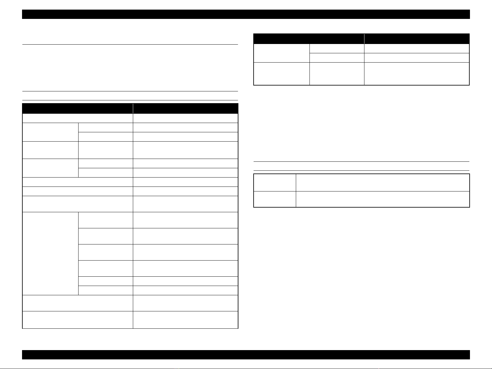
1.1.1 Basic Specifications
PRINTER SPECIFICATIONS
Item Specification
Resolution 600 dpi
Print speed*
(Single-sided / Duplex)
Warm-up time 23°C, 55% RH Less than 109 seconds*
First Print Out*
Dimensions (W x D x H) 648 mm x 608 mm x 477 mm
Weight (excluded consumables) 49.5 kg
Power supply AC 110 ~ 120 V: 50 Hz / 60 Hz ± 3 Hz
Power consumption Max. 110 ~ 120 V: Less than 1340 W
Life*
Durability Average: 4,000 pages / month
1
3
4
Color 25.6 ppm / 23.8 ppm
Monochrome 25.6 ppm / 23.8 ppm
Less than 109 seconds*
Color 11.4 seconds
Monochrome 8.1 seconds
AC 220 ~ 440 V: 50 Hz / 60 Hz ± 3 Hz
220 ~ 240 V: Less than 1390 W
Color printing 110 ~ 120 V: 581 W
220 ~ 240 V: 576 W
Monochrome printing 110 ~ 120 V: 543 W
220 ~ 240 V: 522 W
Ready (Heater ON)
(Average)
Sleep Less than 11 W
Stand by 0 W
110 ~ 120 V: 139 W
220 ~ 240 V: 146 W
600,000 pages or five years, whichever
comes first
Max: 10,000 pages / month
2
(120 V)
2
(230 V)
Item Specification
Noise Printing 52 dB
Standby 40 dB
Storage and
transportation
conditions
*1: Conditions: A4, plain paper, continuous printing
The values vary depending on paper type and size.
*2: Less than 109 seconds from sleep mode. (120 V)
Less than 109 seconds from sleep mode. (230 V)
*3: Paper feeder = MP tray, Standard Cassette or Optional Cassette 1
Paper size = A4
*4: A4, continuous printing, independent of color/monochrome ratio.
*5: No condensation
Temperature and
humidity
Temperature: 0 ~ 35 °C
Humidity: 30 ~ 85 % RH*
5
OPTIONAL UNIT
Optional
cassette
Duplex Unit Paper size: A3F, A3, A4, A5, B4, B5, Letter, LGL, B, GLG, GLT, EXE,
Capacity: Up to 500 sheets
Paper size: A3, A4, B4, B5, Letter, LGL, B, F4
F4, Double postal card, 4-sided postal card
PRODUCT DESCRIPTION Product Specifications 12
Confidential
Page 12
EPSON AcuLaser C9200N Revision D
1
9
8
7
6
5
4
2
3
3
4
5
7
8
6
2
1
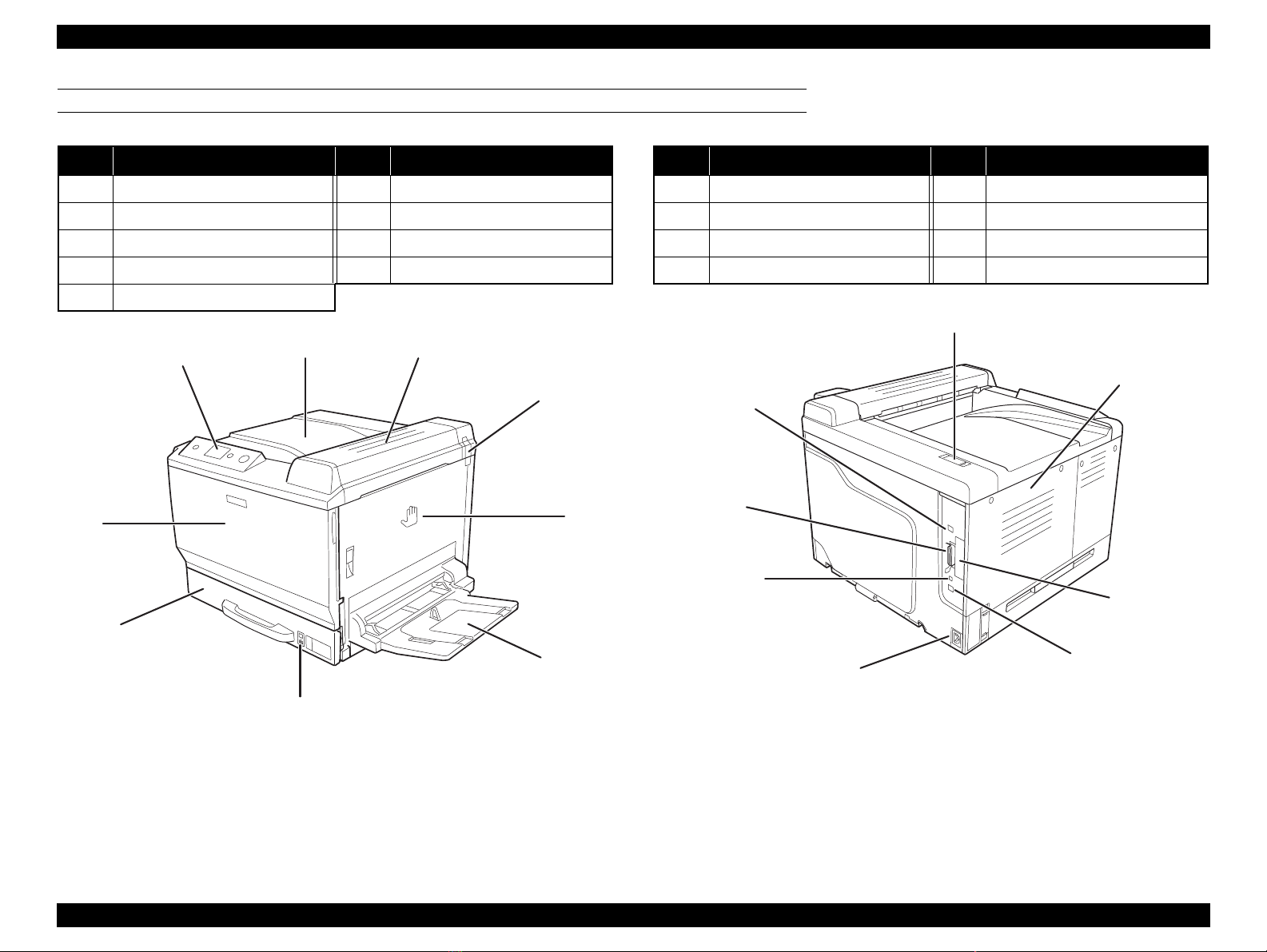
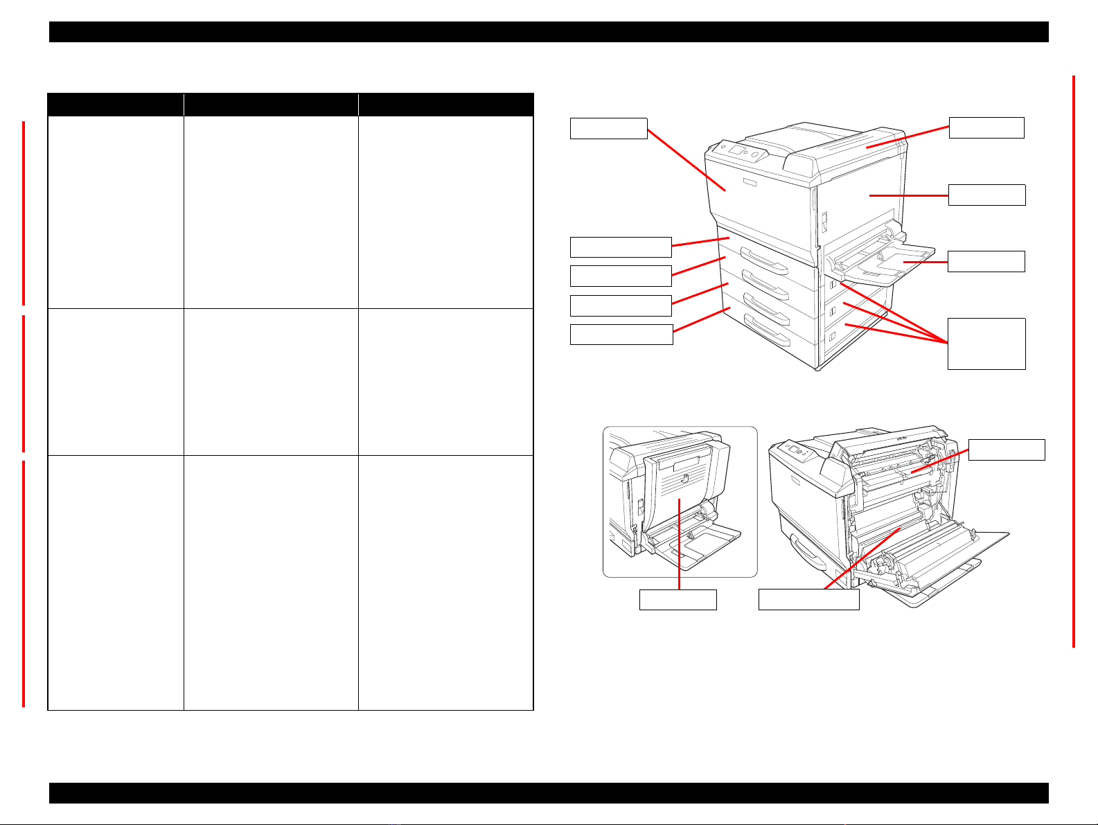
EXTERNAL VIEW AND PART NAMES
Table 1-1. Part Names
No. Name No. Name
1 Control Panel 6 MP Tray
2 Output Tray 7 Paper Indicator
3 Cover B 8 Standard Cassette
4 Odor filter 9 Cover F (Front Door)
5 Cover A (Right Door)
Table 1-2. Part Names
No. Name No. Name
1 Exhaust filter 5 AC inlet
2 Left side cover 6 Service connector
3 Type-B interface card slot cover 7 Parallel interface connector
4 Ethernet interface connector 8 USB interface connector
Figure 1-2. Rear view
Figure 1-1. Front view
PRODUCT DESCRIPTION Product Specifications 13
Confidential
Page 13
EPSON AcuLaser C9200N Revision D
12
13
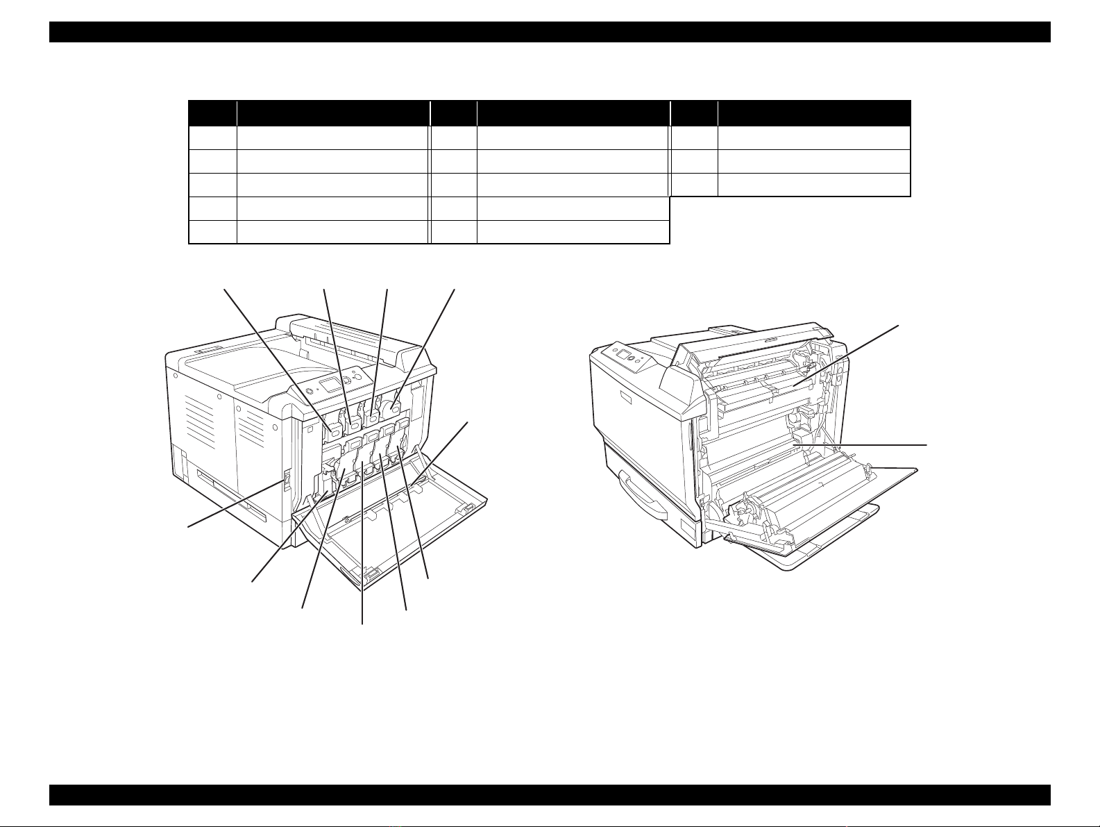
Table 1-3. Part Names
No. Name No. Name No. Name
1 Toner Cartridge (Yellow) 6 Photoconductor unit (Black) 11 Power switch
2 Toner Cartridge (Magenta) 7 Photoconductor unit (Cyan) 12 Cover H
3 Toner Cartridge (Cyan) 8 Photoconductor unit (Magenta) 13 Paper path G
4 Toner Cartridge (Black) 9 Photoconductor unit (Yellow)
5 Exposure window cleaning bar 10 Waste toner collector
1
2
3
4
5
11
10
9
6
7
8
Figure 1-3. Inside the printer
PRODUCT DESCRIPTION Product Specifications 14
Confidential
Page 14
EPSON AcuLaser C9200N Revision D
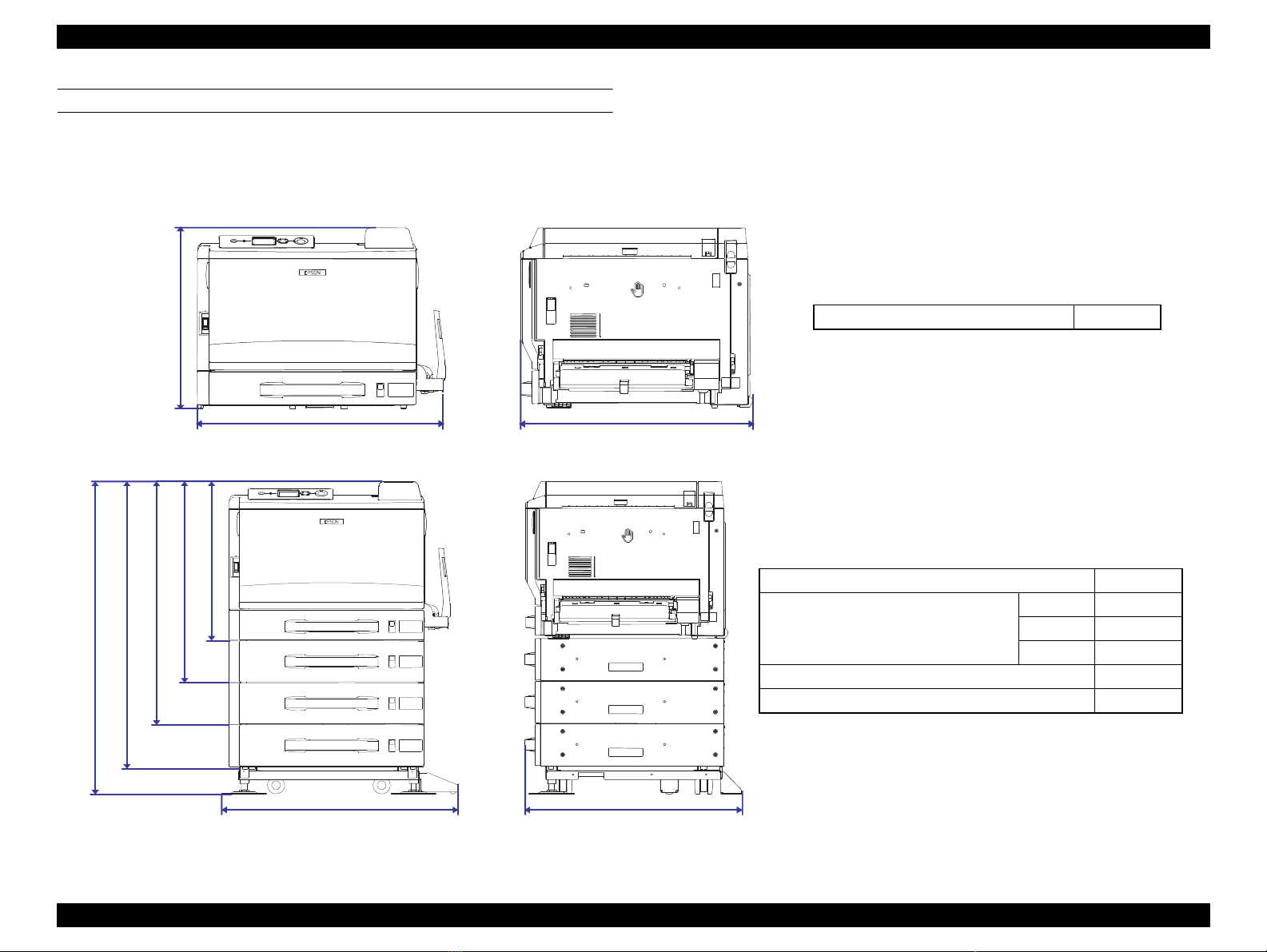
608 mm648 mm
477 mm
Main Unit 49.5 kg
629 mm699 mm
937 mm
Optional Cassette 14.8 kg
Main Unit + Optional Cassette 1 level 64.3 kg
2 levels 79.1 kg
3 levels 93.9 kg
Main Unit + Duplex Unit 52.8 kg
Main Unit + Optional Cassettes (3 levels) + Printer stand 102.4 kg
849 mm
725 mm
601 mm
477 mm
DIMENSIONS AND WEIGHT
The following figure shows the dimensions and weight of the printer.
NOTE 1 : Manufacturing tolerance is ±5 mm in dimensions and ±0.5 kg in weight.
2 : Consumables are not included in the weight of the main unit.
Figure 1-4. Main Unit
Figure 1-5. Main Unit with Optional Units Installed
PRODUCT DESCRIPTION Product Specifications 15
Confidential
Page 15
EPSON AcuLaser C9200N Revision D
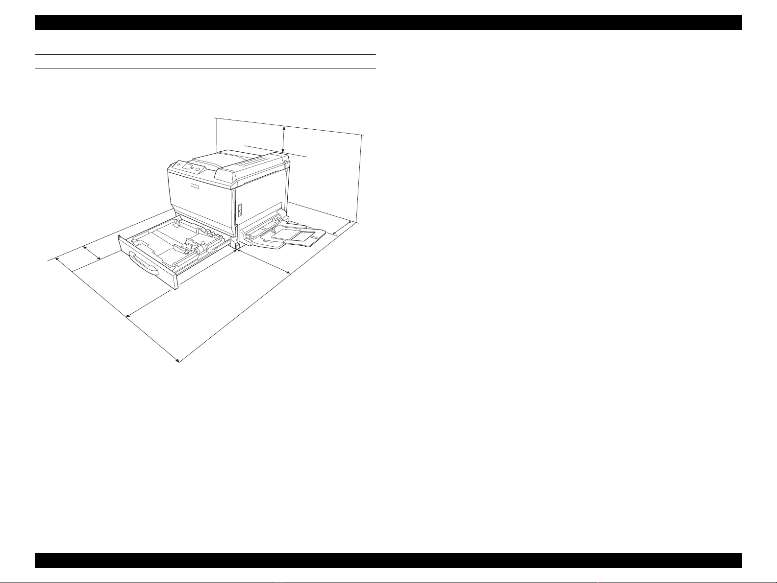
300 mm
200 mm
450 mm
820 mm
1125 mm
100 mm
INSTALLATION SPACE REQUIREMENTS
The following figure shows the dimensions of the space required around the printer.
Be sure to provide the space for installation, operation, and maintenance.
Figure 1-6. Installation Space Requirements
PRODUCT DESCRIPTION Product Specifications 16
Confidential
Page 16

EPSON AcuLaser C9200N Revision D
1.1.2 Paper Specifications
SUPPORTED PAPERS
Table 1-4. Supported Papers
Paper Feeder Paper Type* Paper Size
Capacity
(Height)
Weight
Standard Standard Cassette Plain paper / Recycled paper A3F, A3, A4, A5, B4, B5 250 sheets 64 ~ 90 g/m
MP tray Plain paper / Recycled paper A3F, A3, A4, A5, B4, B5, LT, HLT, GLT, LGL, GLG, EXE, B, F4 100 sheets 64 ~ 90 g/m
Special media Transparency A4, LT 10 sheets ---
Coated Paper A3F, A3, A4 10 sheets --Long Paper Width: 210 mm ~ 297 mm
Length: 458 mm ~ 1,200 mm
1 sheets 127 ~ 160 g/m
Postcard Postcard, Double postal card, 4-sided postal card 10 sheets 190 g/m
Labels A4, LT 10 sheets 91 ~ 209 g/m
Thick paper A3F, A3, A4, A5, B4, B5, LT, HLT, GLT, LGL, GLG, EXE, B, F4 10 sheets 91 ~ 256 g/m
Envelope Monarch, COM-#10, DL, IB5, C5, C6 10 sheets 91 ~ 256 g/m
User defined Width: 90.00 mm ~ 311.20 mm
Length: 139.70 mm ~ 1200.00 mm
--- 64 ~ 256 g/m
Option Optional Cassette Plain paper / Recycled paper A3, A4, B4, B5, LT, LGL, B, F4 500 sheets 64 ~ 90 g/m
Duplex unit Plain paper / Recycled paper / Thick paper A3F, A3, A4, A5, B4, B5, Letter, LGL, B, GLG, GLT, EXE, F4 --- 64 ~ 256 g/m
*: Plain Paper: FX-P (64g/m2), Epson color laser paper (82g/m2)
2
2
2
2
2
2
2
2
2
2
PRODUCT DESCRIPTION Product Specifications 17
Confidential
Page 17

EPSON AcuLaser C9200N Revision D
UNSUITABLE PAPERS
The following types of paper should not be used, otherwise decreased print quality,
paper misfeeds, or damage to the printer may occur.
Specially-treated papers, such as carbon-backed, non-carbon, heat-sensitive,
pressure-sensitive, or acid paper
Extremely thick or extremely thin papers
Damp paper
Art paper, coated paper for color printers
Extremely smooth or extremely rough paper, or paper with uneven surface
Perforated paper or paper with punched hole
Folded, curled, wrinkled, or torn paper
Paper of a non-standard shape (not rectangular)
Label that peels off easily
Papers with glue, staples, or paper clips
Inkjet printer paper (Photo Quality Ink Jet Paper, Glossy Paper, Glossy Film, etc.)
Printouts printed by a heat-transfer printer or an inkjet printer
Transparency for other color laser printers or color photocopiers
Printouts printed by another color/monochrome laser printer or a photocopier
Sheets of paper stuck together using glue or the like
Postcards for inkjet printers
Iron-on Transfer Paper (for inkjet printers or laser printers)
Paper that deteriorates or discolors at 200 °C or lower
When using illustrated postcards, paper feed rollers may be soiled with paper dust
and these cards may not be fed properly. In this case, clean the rollers with
reference to Chapter 6 “MAINTENANCE” (p.331)
PRODUCT DESCRIPTION Product Specifications 18
Confidential
Page 18
EPSON AcuLaser C9200N Revision D
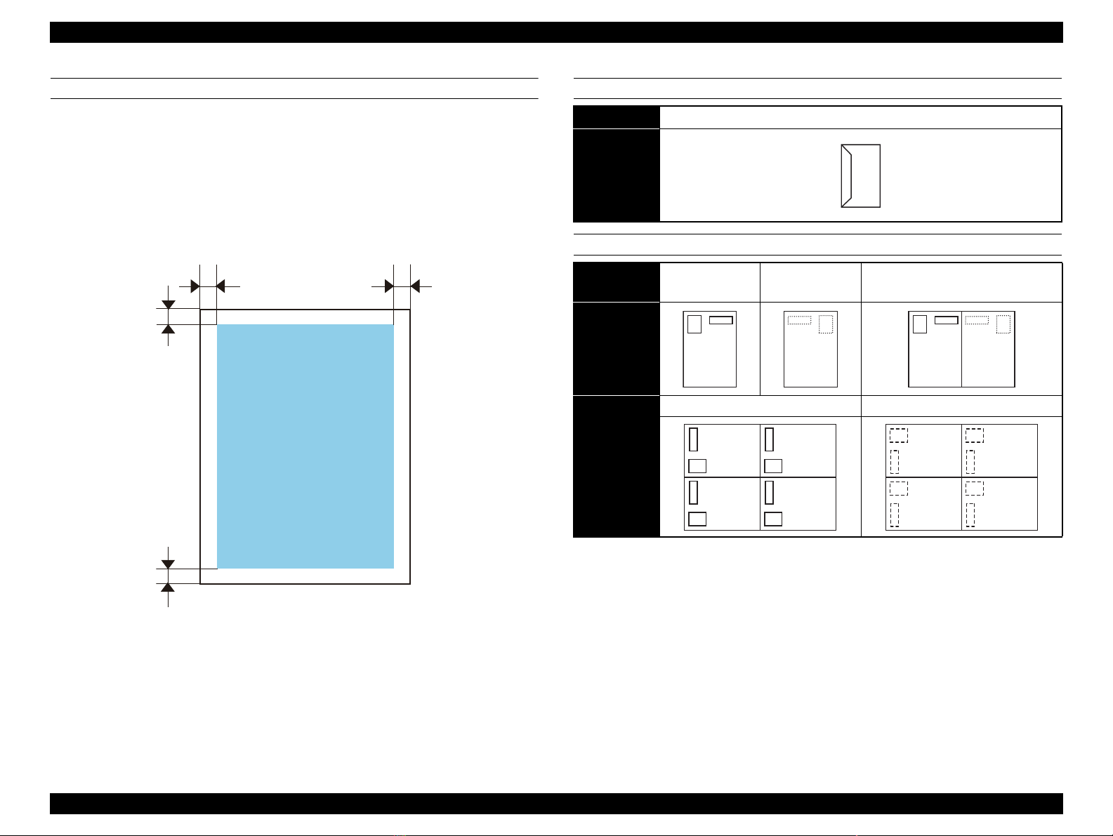
5 mm (7 mm)
5 mm5 mm
5 mm (7 mm)
PRINTABLE AREA
Maximum print area (Printing is guaranteed)
Area excluding 4.2 mm margins on all four edges
(For A3F, all areas except 2 mm from the left and right edges)
Guaranteed print area
Area excluding 5 mm margins on all four edges
(Values in parenthesis ( ) are for A3F)
ENVELOPE ORIENTATION
Envelope Size
Feeding
Direction
↑
POSTCARD ORIENTATION
Postcard type
Feeding
Direction
↑
Feeding
Direction
↑
Postcard Front
side printing
Front side of 4-sided postal card Back side of 4-sided postal card
Monarch, COM-#10, DL, C5, C6
Postcard Reverse
side printing
Front side of double postal card
Back side of double postal card
Table 1-5. Guaranteed Print Area
PRODUCT DESCRIPTION Product Specifications 19
Confidential
Page 19
EPSON AcuLaser C9200N Revision D
1.1.3 Replacement Parts
CONSUMABLES
Load envelopes on the MP tray with the side to be printed face
down.
Before printing on envelopes, set the release lever to envelope
position.
Do not use envelopes that have a tape or glue.
PAPER EJECT/CAPACITY
Paper eject Capacity Remarks
Face down 500*1 sheets
*1: Calculated on FX-P paper (64 g/m2)
*2: Calculated on EPSON color laser paper (82 g/m2)
350
*2
sheets
Applicable to simplex printing only.
Name Life
Toner Cartridge (K) Included in the initial package 5,000 pages
Replacement 21,000 pages
Toner Cartridge (Y/M/C) Included in the initial package 3,500 pages
Replacement 14,000 pages
Photoconductor Unit (K) 50,000 pages
Photoconductor Unit (Y/M/C) 30,000 pages
Waste toner collector 21,000 pages
Odor filter (Included in the K toner cartridge) 15,000 pages
Exhaust fan filter (Included in the waste toner collector) 18,000 pages
PRODUCTS THAT REQUIRE PERIODIC REPLACEMENT
Name Life
Fusing Unit 120,000 pages
Transfer belt unit 120,000 pages
2nd transfer roller (Included in the Transfer belt unit) 120,000 pages
Maintenance Unit (Feed roller for MP tray and Standard cassette) 200,000 pages
Feed roller, Separation roller 200,000 pages
PRODUCT DESCRIPTION Product Specifications 20
Confidential
Page 20
EPSON AcuLaser C9200N Revision D
USB 2.0HS Device Interface
Parallel Interface
USB 2.0HS Host Interface
Ethernet Interface
Type-B Interface
1.1.4 Controller Specifications
BASIC SPECIFICATIONS
CPU 32bit RISC CPU
Enhanced Technology NPGI, PGI, CRIT, RIT
RAM Standard (on-board) 256 MB
Maximum 768 MB
Expansion Type DDR333 CL=2.5
(128 MB, 256 MB, 512 MB)
Numbers of slot 1 slot
ROM Type 32-bit width (3.3V)
Program 32 MB (DIMM)
Font Included in the program
Expansion ROM ROM for Adobe PS3 as a standard
EEPROM Serial type 512 kbit
Control panel 22 digits x 5 lines LCD, three LEDs and seven buttons
Printer language ESC/Page-Color, ESC/Page, FX, ESCP2, I239X,
PCL5c, PCL6, Adobe PostScript3 and PDF1.6
Auxiliary software
Configuration Status Sheet
Supplies Status Sheet
Usage History Sheet
Reserve Job List
Form Overlay List
Network Status Sheet
EpsonNet Config (Web)
USB Ext I/F Status Sheet (only when connected to
D4 compliant USB devices)
AUX Status Sheet (only when Type-B level 3 is
installed)
PS3 Status Sheet
PS3 Font List
ROM A Information (only when optional DIMM
is installed)
EXTERNAL INTERFACES
Standard USB interface
Parallel interface
Ethernet interface
Option Type-B interface
Figure 1-7. External Interfaces
USB 2.0HS Device Interface
Service connector (USB 2.0HS Host Interface)
IEEE1284 compliant
100BaseTX/10BaseT
---
PRODUCT DESCRIPTION Product Specifications 21
Confidential
Page 21
EPSON AcuLaser C9200N Revision D
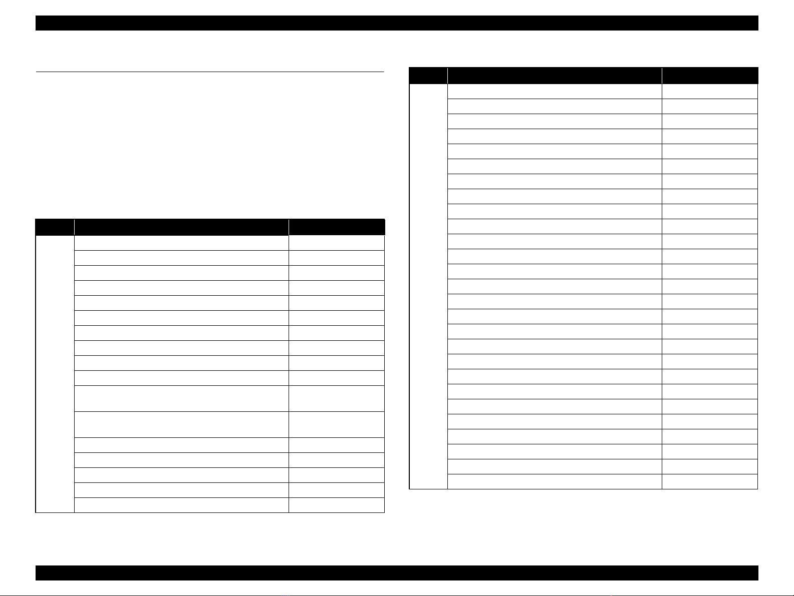
1.2 List of Printer Messages
The following table shows the printer’s LEDs indications in each printer status.
The meanings of the symbols used in the table are as follows.
O: Lights
---: Lights or flashes depending on the conditi on
X: Off
Δ1: Flashes on and off at intervals of 0.3 seconds
Δ2: Flashes on and off at intervals of 0.6 seconds
Table 1-6. List of Printer Messages
Class Printer Status Error LED status
Formatting CF X
ROM CHECK X
RAM CHECK X
CF CHECK X
O
All flashing
---
---
Status
Unable Clear Error
SELF TEST X
Reset All
Reset X
Cancel All Print Job X
Cancel Print Job X
Writing ROM A
Don’t poweroff nnn/mmm
Writing ROM P
Don’t poweroff nnn/mmm
Reset to Save X
Please Select File --Please wait for print --USB Memory Searching Files : nnn --Can't Print File ---
*1
*1
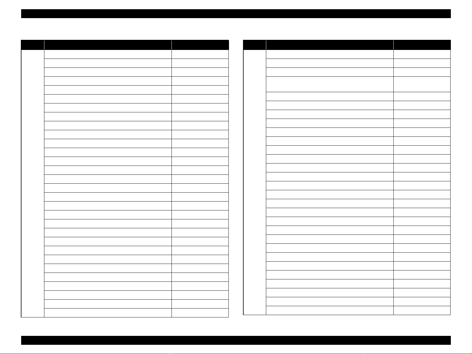
Table 1-6. List of Printer Messages
Class Printer Status Error LED status
X
Status
Form Feed
Printing Configuration Status Sheet X
Printing Supplies Status Sheet X
Printing Usage History Sheet X
ESC/Page Font Sample X
PCL Font Sample X
ESCP2 Font Sample X
FX Font Sample X
I239X Font Sample X
PS3 Status Sheet printing X
PS3 Font List X
Printing Support Status Sheet X
Printing Maintenance Status Sheet X
ROM A Information X
Reserve Job List X
Form Overlay List X
Color Diagnosis Sheet X
Warming Up X
Calibrating Printer X
Offline X
Cancel Print Job X
Sleep X
Preheat Mode X
Ready X
(Printing) X
(Communication with inactive I/F) --(Job being executed (printing OK)) ---
PRODUCT DESCRIPTION List of Printer Messages 22
Confidential
Page 22
EPSON AcuLaser C9200N Revision D
Table 1-6. List of Printer Messages
Class Printer Status Error LED status
X
X
X
Δ2
Warning
Reserve Job Canceled
CompactFlash Full X
Form Data Canceled X
PS3 CompactFlash Full X
Can't Print X
Collate Disabled X
Check Paper Size X
Image Optimum X
Check Paper Type X
Need Memory X
Not Supported USB Device XXX
*2
Format Error ROM A X
Correct time using Time Setting X
Replace Photocon uuuu
*3
Toner Low X
uuuu
Photocon uuuu
*3
*3
Needed Soon X
Waste Toner Box Near Full X
Replace Fuser
Replace Transfer Unit Δ2
Replace Maintenance Unit Δ2
Replace Feed Roller C2 Δ2
Replace Feed Roller C3 Δ2
Replace Feed Roller C4 X
Fuser Needed Soon X
Transfer Unit Needed Soon X
Maintenance Unit Needed Soon X
Feed Roller C2 Needed Soon X
Feed Roller C3 Needed Soon X
Feed Roller C4 Needed Soon X
Non-Genuine Toner Cartridge X
Table 1-6. List of Printer Messages
Class Printer Status Error LED status
*3
*3
All flashing
All flashing
O
*4
*5
*5
*5
*5
*5
*5
*5
*5
*5
*5
O
O
O
O
O
O
O
Δ2
O
O
O
Error
Service Req Cffff
Service Req Eggg
Optional RAM Error O
Format Required
No=LeftSW Yes=OK SW
Write Error ROM A O
Write Error ROM P O
Jam Paper Size Error O
Check Transparency O
Paper Jam w w w w w
Wrong Toner Cartridge uuuu
Toner Cart Error uuuu
Install Photocon uuuu
Install uuuu*5 TnrCart O
Install Waste Toner Box O
Wrong Photocon uuuu
Photocon Trouble uuuu
Replace Photocon uuuu
Replace Photocon uuuu
Replace Toner uuuu
Replace Toner uuuu
NonGenuineToner uuuu
Replace Waste Toner Box O
Replace Fuser O
Replace Fuser Δ2
Replace Transfer Unit Δ2
Replace Maintenance Unit Δ2
Replace Feed Roller C2 Δ2
Replace Feed Roller C3 Δ2
Replace Feed Roller C4 Δ2
PRODUCT DESCRIPTION List of Printer Messages 23
Confidential
Page 23

EPSON AcuLaser C9200N Revision D
Table 1-6. List of Printer Messages
Class Printer Status Error LED status
Set Release Lever to ppp*6 Position O
w w w w*7 Open O
Manual Feed sss Δ2
Turn Paper Cassette1 O
Turn Paper Cassette2 O
Turn Paper Cassette3 O
Turn Paper Cassette4 O
Can’t Print Duplex Δ1
*9
*9
O
Δ1
Error
Paper Out ttt*8 sss
Paper Set ttt*8 sss
Print Overrun Δ1
Memory Overflow Δ1
Duplex Memory Overflow Δ1
Invalid Data Δ1
CompactFlash Error O
Invalid N/W Module O
Invalid PS3 O
Invalid AUX I/F Card O
Invalid ROM A O
Note : Messages in the table are sor ted in the order descending priorities. The message shown
at top of the table has the highest priority.
*1: nnn = Number of written blocks, mmm = total number of blocks
*2: "XXX" is replaced with “Hub” when a USB memory with a hub is in stalled. Otherwise,
it is displayed as a blank.
*3: See
*4: “WWWWW” indicates the jammed or opened point. See
*5: uuuu = Either of the following will appear: C, M,Y, K, Cyan (C), Magenta (M), Yellow
*6: ppp = Either of the following will appear: Envelope, Normal.
*7: Error location
*8: Displays relevant values of the paper source in the panel setting except Auto.
*9: Displays relevant values of each paper feed size of the Tray menu in the panel setting.
“3.3.3 Controller Related Error” (p.129) for details.
“3.2.1 Checking a paper
jam type and jammed location” (p.99)
(Y), Black (K). Only when a message exceeds the display digit in full spelling,
abbreviated forms (C, M, Y, K) will appear.
.
PRODUCT DESCRIPTION List of Printer Messages 24
Confidential
Page 24

EPSON AcuLaser C9200N Revision D
1.2.1 Error Message and Troubleshooting
Table 1-7. Error Message and Troubleshooting
Message Explanation Remedy
A CompactFlash which does not
have two partitions has been
installed.
Format Required
No=LeftSW
Yes=OK SW
Paper Jam
W W W W W
Check Transparency
NonGenuineToner uuuu
Toner Cartridge Error
uuuu
An unformatted CompactFlash
has been installed.
The printer is turned on after
executing "Format
CompactFlash" or "Delete All
CompactFlash Data" of the
Support Menu.
Paper jam in the displayed area.
Transparency is specified, but
media other than transparencies
were fed. Or transparency is not
specified, but transparencies was
fed.
The toner cartridge of the
specified color is non-genuine.
The toner cartridge of the
specified color is out of order.
l
Press the OK button to
format the CompactFlash.
Turn off the printer without
any operation and remove
the CompactFlash.
Remove the jammed paper and
close the cover. Printing will be
started again from where the jam
occurred. Refer to Figure 1-8.
Remove the media from the MP
Tray. Open and close cover F.
Load the correct media to start
printing again from where the
jam occurred.
The error is cleared either by
replacing it with a genuine toner
or selecting continuing use
according to the user
confirmation flow.
1. Replace the ton er cartridge of
the specified color with a
normal one.
2. Replace with a new toner
cartridge.
If the error is not cancelled, turn
the printer off and on again.
Table 1-7. Error Message and Troubleshooting
Message Explanation Remedy
1. Replace the photoconductor
Photocon Trouble uuuu
Install uuuu TnrCart
Install Photocon uuuu
Wrong Toner uuuu
Replace Toner uuuu
Install Waste Toner Box
Wrong Photocon uuuu
The photoconductor unit of the
specified color is out of order.
The toner cartridge of the
specified color is not
installed. Or it is not
installed correctly.
The tape has not been
removed from the toner
cartridge of the specified
color.
The photoconductor unit of
the specified color is not
installed. Or it is not
installed correctly.
The tape has not been
removed from the
photoconductor unit of the
specified color.
The toner cartridge of the
specified color is invalid
(different destination).
Printing has stopped because
the toner cartridge of the
specified color has reached
its lifetime.
Cannot be cleared by the
Start/Stop switch.
The waste toner box is not
installed. Or it is not installed
correctly.
The photoconductor unit of the
specified color is invalid
(different destination).
2. Replace with a new
If the error is not cancelled, turn
the printer off and on again.
Install the toner cartridge for
If a toner cartridge is
Install the photoconductor
If a photoconductor unit is
Replace with a legitimate toner
cartridge.
Replace with a new toner
cartridge of the specified color.
Install a waste toner box.
Replace with a legitimate
photoconductor unit.
unit of the specified color
with a normal one.
photoconductor unit.
the specified color.
installed, remove it, remove
the tape, and reinstall it.
unit for the specified color.
installed, remove it, remove
the tape, and reinstall it.
PRODUCT DESCRIPTION List of Printer Messages 25
Confidential
Page 25

EPSON AcuLaser C9200N Revision D
Table 1-7. Error Message and Troubleshooting
Message Explanation Remedy
Error LED flashing
Printing has stopped because
the photoconductor unit of
Replace Photocon uuuu
Replace Waste Toner
Box
Replace Fuser
Replace Transfer Unit
Replace Maintenance
Unit
the specified color has
reached its lifetime.
Cannot be cleared by the
Start/Stop switch.
The waste toner box is at the
end of its product lifetime.
Cannot be cleared by the
Start/Stop switch.
Printing has stopped because
the fuser unit has reached its
lifetime.
Can be cleared by the Start/
Stop switch.
Printing has stopped because
the transfer unit has reached
its lifetime.
Can be cleared by the Start/
Stop switch.
Printing has stopped because
the maintenance unit has
reached its lifetime.
Can be cleared by the Start/
Stop switch.
Error LED On
Replace with a new waste toner
box.
Error LED flashing
Error LED On
Replace with a new transfer
Press the Start/Stop switch to
Replace with a new
Press the Start/Stop switch
Replace with a new
photoconductor unit of
the specified color.
Press the Start/Stop
switch to clear the error
and continue printing.
Replace with a new
photoconductor unit of the
specified color.
Replace with a new fuser
unit.
Press the Start/Stop
switch to clear the error
and continue printing.
Replace with a new fuser
unit.
unit.
clear the error and continue
printing.
maintenance unit. After
replacement, perform Reset
Maint Counter on the panel.
to clear the error and
continue printing.
Table 1-7. Error Message and Troubleshooting
Message Explanation Remedy
Contact Service and replace
Printing has stopped because
the paper feed roller has
Replace Feed Roller xxx
Set Release Lever to ppp
Position
wwww Open A cover is open.
reached its lifetime.
Can be cleared by the Start/
Stop switch.
Displayed when there is an
envelope print request after
printing plain paper, or a plain
paper print request after printing
envelopes, prompting the user to
set the release lever to the
correct position.
Press the Start/Stop switch to
Open cover A, set the release
lever to the position shown in
the message, and close cover A.
The error is cleared by closing
the cover specified. Refer to
Figure 1-8.
the paper feed roller. After
replacement, perform Reset
xxx Counter on the panel.
clear the error and continue
printing.
PRODUCT DESCRIPTION List of Printer Messages 26
Confidential
Page 26
EPSON AcuLaser C9200N Revision D
cover F
cassette 1 (C1)
cassette 2 (C2)
cassette 3 (C3)
cassette 4 (C4)
cover E2
cover E3
cover E4
MP tray
cover A
cover B
cover D
cover H
paper path G
Table 1-7. Error Message and Troubleshooting
Message Explanation Remedy
The installed CompactFlash
cannot be used on this printer or
it is a CompactFlash of less than
Invalid CompactFlash
Error
Can't Print Duplex
Turn Paper Cassette 1
(2,3,4)
4 GB, or "No" is selected when
"Format Required" occurred.
This error also occurs under the
following conditions for a
CompactFlash with the
password lock function.
Password lock has failed.
Could not unlock the
password lock.
An error resulted as printing was
specified with conditions where
duplex printing is not possible.
An error occurred because the
width of the paper set in the
feeder device was narrower than
the width set for printing. With
this printer, the error occurs
when the following conditions
are met at the same time.
The width of the paper size
specified for printing is
210.00mm or more.
The paper set is less than
210.00 mm wide.
The envisioned situation is when
normally horizontally set A4,
A5, B5, or LT is mistakenly set
vertically.
Turn off the printer, remove
the CompactFlash, and turn
on the printer.
Select "Yes" to format the
CompactFlash when "Format
Required" occurs.
This error is cleared by
pressing the Start/Stop
switch and the printer prints
in simplex.
When Auto Continue is on,
simplex printing starts after a
certain interval.
If printing does not continue,
cancel the job.
When the specified paper
size is correct
Remove the paper from the
cassette displayed and set the
correct paper. The error is
cleared and printing starts.
When the set paper is correct
Cancel the job for which the
error occurred, and resend
the data with the correct
paper size specified.
Figure 1-8. cover
PRODUCT DESCRIPTION List of Printer Messages 27
Confidential
Page 27

EPSON AcuLaser C9200N Revision D
1.2.2 Warning Message and Troubleshooting
Table 1-8. Warning Message and Troubleshooting
Message Explanation Remedy
Reserve Job Canceled
CompactFlash Full
Form Data Canceled
PS3CompactFlash Full
An attempt has been made to
register a new Re-Print Job, Verify
Job, Stored Job or Confidential Job
though the number of registrations
has reached the maximum.
When the user attempted to register
a Re-Print Job or Verify Job, there
was already a Stored Job registered
by same user name or job name.
Insufficient capacity of RAM disk.
Or, RAM Disk is set to Off.
Insufficient capacity of
CompactFlash. Or, a
CompactFlash is not installed.
The CompactFlash memory is full
and collated print jobs, form data,
reserve jobs etc. cannot be saved.
The user attempted registration
after reaching the maximum
number.
The USB memory is not installed,
or was removed while registering.
Or, the capacity of the USB
memory is insufficient.
A CompactFlash is not installed. Install a CompactFlash.
When downloading PS3 fonts, the
CompactFlash memory is full and
the fonts cannot be saved.
Delete or print the registered
Re-Print Jobs, Verify Jobs,
Stored Jobs or Confidential
Jobs.
When there is another Stored
Job with the same user name or
job name, either change the job
name and register it or delete
the Stored Job.
Set RAM Disk to Normal or
Maximum if RAM Disk is set
to Off. Increase the RAM Disk
capacity or add more RAM if
RAM Disk is already set to
Normal or Maximum.
Install a CompactFlash if a
CompactFlash is not installed.
Delete unnecessary form data
and Reserve Jobs (Re-Print,
Verify, Stored, and
Confidential).
Delete registered forms. Or,
replace the USB memory.
Check if the USB memory is
installed. Or, replace with
another USB memory with a
larger capacity.
Delete previously downloaded
fonts to empty the
CompactFlash memory.
Table 1-8. Warning Message and Troubleshooting
Message Explanation Remedy
Data was disregarded and not
printed due to a problem in the
data. The following are conditions
of this warning.
Bandwidth of the received data
Can't Print
Check Paper Size
Image Optimum
Not Supported USB
Device xxx
does not match the value
determined by the paper size.
The received data contains
undefined intermediate codes or
compression format.
Checksums attached to the
intermediate code data using
ESC/Page and ESC/Page-Color
do not match checksums of the
actual data.
Data cannot be read from the
USB memory where print data
is stored.
The paper size for the loaded paper
and specified paper do not match.
Printing with PS
This warning occurs when
memory is insufficient, and the
resolution is reduced.
Printing with the ESC/Page-
Color driver or EPSON PCL
driver
This warning occurs when data
is compressed with a higher
level of compression.
The USB device (other than a
memory device) or a USB memory
with a hub currently connected to
the USB port is not supported. A
file check is performed whenever a
new device is found on the USB
port, and this error occurs at the
point.
This error occurs when a
printer driver for a different
printer is used. Check the
printer and reinstall it if it is an
incorrect driver. When printing
from a USB memory, check
and reinsert the USB memory.
Set the paper of the specified
size.
Printing with PS
ESC/Page-Color driver or
Disconnect the USB memory
from the USB port, or specify
Clear Warning to clear the
warning.
Add memory.
EPSON PCL driver
Set the priority of the driver
data compression method
to quality.
PRODUCT DESCRIPTION List of Printer Messages 28
Confidential
Page 28

EPSON AcuLaser C9200N Revision D
Table 1-8. Warning Message and Troubleshooting
Message Explanation Remedy
Correct time using
Time Setting
Replace Photocon uuuu
uuuu Toner Low
Photocon uuuu Needed
Soon
The printer has not been turned on
for 10 days or longer and the
capacitor has been
discharged.
The photoconductor unit for the
specified color has reached its
lifetime when it has been
continuously used after the
"Replace Photocon uuuu" error.
The print quality is not guaranteed
while this message is being
displayed.
Message warning that remaining
toner is low for the specified color.
Message warning that the
photoconductor unit of the
specified color is approaching the
end of its lifetime.
Set the date and time again
from Time Setting. This
warning recurs until they are
set again.
Replace with a new
This message is cancelle d
This message is cancelled by
one of the following.
Executing Clear All
Executing Reset in the
Replace with a new toner
This message is cancelled by
one of the following.
Executing Clear All
Executing Reset in the
Replace with a new
photoconductor unit of the
specified color.
by one of the following.
Executing Clear All
Warnings in the Reset
Menu.
Executing Reset in the
Reset Menu.
Warnings in the Reset
Menu.
Reset Menu.
cartridge of the specified
color.
Warnings in the Reset
Menu.
Reset Menu.
photoconductor unit of the
specified color.
Table 1-8. Warning Message and Troubleshooting
Message Explanation Remedy
This message is cancelled by
one of the following.
Executing Clear All
Waste Toner Box Near
Full
Replace Fuser
Replace Transfer Unit
Replace Maintenance
Unit
Message warning that the waste
toner box is approaching the end of
its lifetime.
Message warning that the fuser
unit has reached the end of its
lifetime when it has been
continuously used after the
"Replace Fuser" error. The print
quality is not guaranteed while this
message is being displayed.
Message warning that the transfer
unit has reached the end of its
lifetime when it has been
continuously used after the
"Replace Transfer Unit" error. The
print quality is not guaranteed
while this message is being
displayed.
Message warning that the
maintenance unit has reached its
lifetime when it has been
continuously used after the
"Replace Maintenance Unit" error.
The print quality is not guaranteed
while this message is being
displayed.
Executing Reset in the
Replacing the waste toner
This message is cancelled by
one of the following.
Executing Clear All
Executing Reset in the
Replacing the fuser unit
This message is cancelled by
one of the following.
Executing Clear All
Executing Reset in the
Replacing the transfer unit
This message is cancelled by
one of the following.
Executing Clear All
Executing Reset in the
Replacing the maintenance
Warnings in the Reset
Menu.
Reset Menu.
box with a new one.
Warnings in the Reset
Menu.
Reset Menu.
with a new one.
Warnings in the Reset
Menu.
Reset Menu.
with a new one.
Warnings in the Reset
Menu.
Reset Menu.
unit with a new one.
PRODUCT DESCRIPTION List of Printer Messages 29
Confidential
Page 29

EPSON AcuLaser C9200N Revision D
Table 1-8. Warning Message and Troubleshooting
Message Explanation Remedy
This message is cancelled by
one of the following.
Executing Clear All
Executing Reset in the
Replacing the feed roller
This message is cancelled by
one of the following.
Executing Clear All
Executing Reset in the
Replacing the fuser unit
This message is cancelled by
one of the following.
Executing Clear All
Executing Reset in the
Replacing the transfer unit
This message is cancelled by
one of the following.
Executing Clear All
Executing Reset in the
Replacing the maintenance
Replace Feed Roller
xxx
Fuser Needed Soon
Transfer Unit Needed
Soon
Maintenance Unit
Needed Soon
Message warning that the paper
feed roller has reached the end of
its lifetime when it has been
continuously used after the
"Replace Feed Roller xxx" error.
The print quality is not guaranteed
while this message is being
displayed.
The fuser unit is approaching its
lifetime.
The transfer unit is approaching its
lifetime.
This message appears when the
maintenance unit is approaching its
lifetime.
Warnings in the Reset
Menu.
Reset Menu.
with a new one.
Warnings in the Reset
Menu.
Reset Menu.
with a new one.
Warnings in the Reset
Menu.
Reset Menu.
with a new one.
Warnings in the Reset
Menu.
Reset Menu.
unit with a new one.
Table 1-8. Warning Message and Troubleshooting
Message Explanation Remedy
This message is cancelled by
one of the following.
Executing Clear All
Feed Roller xxxNeeded
Soon
Non-Genuine Toner
Cartridge
Message warning that the paper
feed roller is approaching the end
of its lifetime.
Warning message that the toner
cartridge is non-genuine when
selecting continued use in the user
confirmation flow.
Executing Reset in the
Replacing the feed roller
This message is cancelled by
one of the following.
Replacing with a genuine
Executing Clear All
Executing Reset in the
The message occurs when the
power is turned on again until
the cartridge is replaced with a
genuine product.
Warnings in the Reset
Menu.
Reset Menu.
with a new one.
toner cartridge.
Warnings.
Reset Menu.
PRODUCT DESCRIPTION List of Printer Messages 30
Confidential
Page 30

OPERATING PRINCIPLES
CHAPTER
2
Confidential
Page 31

EPSON AcuLaser C9200N Revision D
DrumBk
1.Charging
2.Exposure
3.Developing
5.Cleaning
DrumC
1.Charging
2.Exposure
3.Developing
5.Cleaning
DrumM
1.Charging
2.Exposure
3.Developing
5.Cleaning
DrumY
1.Charging
2.Exposure
3.Developing
5.Cleaning
4. Primary transfer (Drum→Intermediate Transfer Belt)
Transfer belt
8. Cleaning
Paper
7.Electrical discharge
9.Fusing
6. Secondary transfer (Intermediate
Transfer Belt
→Paper)
2.1 Print Process
This printer is a "Full color page printer" that uses the principle of
electrophotographic recording. Each YMCK color (yellow, magenta, cyan,
black) has its own special drum (Photoconductor (PC) drum) and developer
that are used in tandem. Since each color is developed simultaneously, the
color image can be printed at high speed comparing to the four cycles engine
printer. The transfer intermediate is coordinated, and at the end of the process
the layered color toner images produce a full color print. The major steps of the
print process are described below.
1. Charging: The PC Drum surfaces are charged with electricity.
2. Exposure: Imag e areas are exposed on PC Drum with laser radiation.
3. Developing: Image areas on drums are developed with toner.
4. Primary transfer: The toner image on PC Drum is transferred to Intermediate
Transfer Belt.
5. Cleaning: PC Drum are cleaned.
6. Secondary transfer: The complete four-color toner image on the Intermediate
7. Electrical discharge:The electrical charge of the paper is discharged.
Transfer Belt is transferred to the paper.
8. Cleaning: Intermediate Transfer Belt are cleaned.
9. Fusing: Ton e r on the paper is fused with heat and pressure.
OPERATING PRINCIPLES Print Process 32
Figure 2-1. Print Process
Confidential
Page 32

EPSON AcuLaser C9200N Revision D
[1]
[3]
[4]
[5]
[6]
[2]
[7][8][9][10]
[11]
[12]
[13]
[14]
[15]
[17]
[16]
[18]
[19]
4039T1C102AA
1. Fusing Unit
2. Transfer Belt Unit
3. 2nd Transfer Roller
4. MP tray
5. Standard Cassette
6. Optional Cassette
7. Print Head Unit (PH Unit) /K
8. Print Head Unit (PH Unit) /C
9. Print Head Unit (PH Unit) /M
10. Print Head Unit (PH Unit) /Y
11. Waste Toner Collector
12. Photoconductor Unit/Y
13. Photoconductor Unit/M
14. Photoconductor Unit/C
15. Photoconductor Unit/K
16. Toner Cartridge/Y
17. Toner Cartridge/M
18. Toner Cartridge/C
19. Toner Cartridge/Y
2.2 Operating Principle of Main Unit Mechanism
2.2.1 Center cross section
Figure 2-2. Center cross section
OPERATING PRINCIPLES Operating Principle of Main Unit Mechanism 33
Confidential
Page 33

EPSON AcuLaser C9200N Revision D
4039T1C103AA
PAPER PATH
Normally, papers are supplied from 2 bins. MP tray (100 papers) and Standard
cassette (250 papers).
5 bins of paper supply can be available by setting maximum three optional
cassette (500 papers).
A Paper supplied from each Tray is transported to the Vertical Transport
then an image is transferred in the 2nd Transfer Roller and fused in the
Fusing Unit. Finally, the paper is exited with face down.
Duplex mechanism of this machine uses circuit system. The major steps of
Duplex are described below (When two documents are printed in Duplex).
1. Firstly, printing back up (back side of the paper) is executed. After an image
is fused, the transfer route is switched at Paper exit section and the paper is
drawn back inside the Duplex Unit.
2. The paper is reversed and transported from the Duplex Unit to the paper
route in front of the Registration Roller.
3. Printing the front page (surface of the paper) is executed and after an image
is fused, papers are exited to the Exit tray.
Figure 2-3. Paper path
OPERATING PRINCIPLES Operating Principle of Main Unit Mechanism 34
Confidential
Page 34

EPSON AcuLaser C9200N Revision D
4039F5C501DA
[1]
[10]
[9]
[8]
[7]
[2]
[3]
[4]
[5]
[6]
4039F5C502DA
[1]
[2]
[3]
[4]
[5]
[7]
[6]
[8]
[9]
[10]
[11]
[12]
2.2.2 Parts layout drawing
ENGINE SECTION
[1] IDC/Registration Sensor/2 (SE2) [6] Controller Board (PWB-P)
[2] IDC/Registration Sensor/1 (SE1) [7] Program ROM DIMM (WORK0)
[3] Control Panel (PWB-OP) [8] RTC Board (PWB-RTC)
[4] PH Interface Board (PWB-D) [9] Mechanical Control Board (PWB-M)
[5] DC Power Supply (PU1) [10] High Voltage Unit (HV1)
OPERATING PRINCIPLES Operating Principle of Main Unit Mechanism 35
[1] Fusing Drive Motor (M4) [7] Cooling Fan Motor/1 (M12)
[2] Main Motor (M1) [8] Toner Supply Motor Y/M (M6)
[3] Fusing Cooling Fan Motor/2 (M11) [9] Cooling Fan Motor/2 (M22)
[4] Power Supply Cooling Fan Motor/1 (M8) [10] Toner Supply Motor C/K (M7)
[5] Ozone Ventilation Fan Motor (M14) [11] Color PC Drum Motor (M2)
[6] Color Developing Motor (M3) [12] Fusing Cooling Fan Motor/1 (M13)
Confidential
Page 35

EPSON AcuLaser C9200N Revision D
4039F5C503DA
[3]
[1]
[2]
[4]
[5]
[6]
[10]
[9]
[8]
[7]
4039F5C504DA
[5]
[3]
[1]
[2]
[4]
[6]
[8]
[10]
[9]
[7]
[12]
[13]
[11]
[1] Right Door Switch (S5) [6] Front Door Switch/2 (S4)
[2] Primary Interlock Switch (S2) [7] Main Erase Lamp/Y (LA4)
[3] PH Unit [8] Main Erase Lamp/M (LA3)
[4] Main Power Switch (S1) [9] Main Erase Lamp/C (LA2)
[5] Front Door Switch/1 (S3) [10] Main Erase Lamp/K (LA1)
[1] Developing Clutch/K (CL4) [8] Waste Toner Full Sensor (PC8)
[2] Exit Sensor (PC2) [9] Color PC Drive Main Sensor (PC17)
[3] Temperature/Humidity Sensor (SE3) [10] Color PC Drive Sub Sensor (PC18)
[4] Registration Roller Sensor (PC1) [11] Black PC Drive Main Sensor (PC15)
[5] OHP Sensor (PC4) [12] Black PC Drive Sub Sensor (PC16)
[6] Registration Roller Clutch (CL1) [13] 1st Image Trans f er P ressure/Retraction
[7] 1st Image Transfer Pressure/Retraction
Clutch (CL3)
Position Sensor (PC6)
OPERATING PRINCIPLES Operating Principle of Main Unit Mechanism 36
Confidential
Page 36

EPSON AcuLaser C9200N Revision D
A
4038T2C171AA
[1]
[3]
[2]
4039T2C113AA
4038T2C026DB
[4]
[5]
[7]
[10]
[9]
[11]
[8]
[6]
STANDARD CASSETTE
4038T2C111A
[1] Registration Roller Sensor (PC1) [7] Standard Cassette CD Paper Size Sensor
(PC9)
[2] Standard Cassette Feed Roller [8] Standard Cassette Separation Roller
[3] Standard Cassette Separation Roller [9] Standard Cassette Feed Roller (Bypass)
[4] Standard Cassette Device Detection
Sensor (PC12)
[5] Standard Cassette Paper Near-Empty
Sensor (PC11)
[6] Standard Cassette Paper Size Board
(PWB-I)
[10] Standard Cassette Paper Empty Sensor
(PC10)
[11] Standard Cassette Paper Feed Clutch
(CL2)
OPERATING PRINCIPLES Operating Principle of Main Unit Mechanism 37
Confidential
Page 37

EPSON AcuLaser C9200N Revision D
4039T2C106AA
4038T2C008AA
PH Unit
4038T2C034AA
SOS Mirror
Laser Diode
Polygon Motor
SOS Sensor
4038t2J005AB
Transfer Belt
2nd Transfer
Roller
LD/K
LD/Y LD/M
LD/C
PC Drum
YM
C
K
Beam A
Beam B
PC Drum
Return Mirror 1Return Mirror 2
Laser Diode
Beam A
Beam B
Direction
of rotation
of the PC
Drum
Two lines
One scan
Surface of the PC Drum
Polygon
Mirror
G2 Lens
G1 Lens
2.2.3 PH Unit
2.2.3.1 Composition
2.2.3.2 Operation
OUTLINE
4 types of the PH Unit are used for exposure process.
The surface of the Photo Conductor is irradiated with a laser light and an
electrostatic latent image is thereby formed.
2 Beam Array LD is used to prevent the rotation speed from increasing
caused by decreasing the number of the sides comparing to Polygon Mirror
which has four sides.
2 Beam Array LD scans in two lines two lasers irradiated by two LD
electrical components set up vertically with one side of Polygon Mirror.
Figure 2-4. Composition
Figure 2-5. Overview
OPERATING PRINCIPLES Operating Principle of Main Unit Mechanism 38
Confidential
Page 38

EPSON AcuLaser C9200N Revision D
Shutter
Shutter Guide
Void width: 4 mm/0.157 inch
Void width: 4 mm/0.157 inch
Void width: 4.2 mm/
0.165 inch
Void width: 4.2 mm/
0.165 inch
LASER SHUTTER MECHANISM
There is a shutter mechanism provided to prevent the PH from being
contaminated with foreign matter such as dust when the front cover is opened,
or prevent the emission laser from leaking outside for any reason.
The Shutter operates relative to the removing and inserting Photoconductor
Unit because PH Unit is not exposed concerning the layout of the unit when
Photoconductor Unit is inserted. The shutter opens by pressing shutter guide at
insertion of the Photoconductor Unit, and closes at de-installation of the
Photoconductor Unit.
LASER EMISSION AREA
Main scan direction (CD)
The print start position is determined by the start signal for main scan
print and the range of the paper size output from the Mechanical
Control Board (PWB-P).
The laser emission area is determined by the paper size. The area of 4 mm/
0.157 inch on both edges of the paper is, however, the void image area.
Sub scan direction (FD)
The print start position is determined by the writing image signal and the
range of the paper size output from the Mechanical Control Board (PWB-P).
The laser emission area is determined by the paper size. The area of 4.2
mm/0.165 inch on the leading and trailing edges and 4 mm/0.157 inch
on both the side edges of the paper are, however, the void image area.
Start signal
for main
scan print
Writing
image
signal
Figure 2-6. Laser shutter mechanism
4138to2595c0
Figure 2-7. Laser emission area
OPERATING PRINCIPLES Operating Principle of Main Unit Mechanism 39
Confidential
Page 39

EPSON AcuLaser C9200N Revision D
Transfer Belt
IDC/Registration Sensor/1 and /2
(SE1, SE2)
4038T2C033DA
REGISTRATION CONTROL (COLOR SHIFT CORRECTION) SYSTEM
In a tandem engine, in which an independent image reproduction process is
provided for each of the four different colors of toner. Incorrect color
registration, or color shift, is therefore more likely to occur due to each of
the PH Units being out of correct position. The color shift correction
system automatically detects any misalignment among the different colors,
correcting it both in the main scanning and sub scanning directions.
The color shift correction is made when the Front Door is opened and
closed, the Transfer Belt is removed and reinstalled, the Main Power
Switch is turned OFF and ON, or "Calibration" is carried out from the
Control Panel.
SKEW CONTROL MECHANISM
When the PH Unit is mounted on the main body installation plate, image
distortion (skew) occurs due to mounting error. Therefore the PH Unit
adopts the correction system.
Figure 2-9. Skew Control Mechanism 1
The main body skew can be corrected by adjusting the dial of the
corresponding PH Unit (Y, M, C).
Figure 2-8. Registration Control (Color Shift Correction) System
Figure 2-10. Skew Control Mechanism 2
OPERATING PRINCIPLES Operating Principle of Main Unit Mechanism 40
Confidential
Page 40

EPSON AcuLaser C9200N Revision D
4038T2C010AA
4038T2C009AA
4039T2C107AA
Photoconductor Unit/Y, M, C
Photoconductor Unit/K
Cleaning Blade
PC Drum/Y, M, C, K
Toner Collecting Screw
Developing Unit/
Y, M, C, K
PC Drum Charge Corona/
Y, M, C, K
Developing
Clutch/K (CL4)
Color PC Drum
Motor (M2)
Color Developing
Motor (M3)
Main Motor (M1)
2.2.4 Photoconductor Unit section (PU section)
2.2.4.1 Composition
2.2.4.2 Drive
Figure 2-12. Drive Overview
OPERATING PRINCIPLES Operating Principle of Main Unit Mechanism 41
Figure 2-11. Composition
Confidential
Page 41

EPSON AcuLaser C9200N Revision D
0
Operation when a new PU is detected
Transfer Belt
is retracted
TCR
automatic
adjustment
Transfer Belt
cleaning
1st image transfer/
auto transfer
voltage control
adjustment
Image
stabilization
Transfer
Belt is
retracted
Transfer Belt
cleaning
1st image transfer/
auto transfer
voltage control
adjustment
Operation when a new PU is not detected
Image
stabilization
2.2.4.3 Operation
PU LIFE CONTROL
Each PU has IC chip that detects a new PU, keeps track of the service life of
the PU and installation.
New PU detection
New PU is detected when the Main Power Switch is turned ON and the
Front Door is closed.
When a new PU is detected, a TCR adjustment sequence is carried out.
When life is reached
PU Life is detected by the PU Life counter value.
When the PU Life counter value is reached to the near life value, the
warning message "Photocon xxxx Needed Soon" is displayed.
When the PU Life counter value is reached to the life value, the
warning message "Replace Photocon xxxx" is displayed.
4036ma2133c
4038T2C009AA
Figure 2-13. Detection of new PU
OPERATING PRINCIPLES Operating Principle of Main Unit Mechanism 42
Confidential
Page 42

EPSON AcuLaser C9200N Revision D
4036ma2338c0
Charge Transport Layer (CTL)
Charge Generating Layer (CGL)
Aluminum Cylinder
PC Drum
Main Motor (M1)
PC Drum/K
PC Drum/C
PC Drum/M
PC Drum/Y
Color PC Drum Motor (M2)
2.2.5 Photo Conductor section
2.2.5.1 Composition
2.2.5.2 Drive
PC DRUM DRIVE MECHANISM
Two independent PC Drum Motors (for color and monochrome) are used for
the drive mechanism.
The Color PC Drum Motor drives the PC Drums/Y, M, and C, while the Main
Motor drives the PC Drum/K.
.
4038T2C013AA
OPERATING PRINCIPLES Operating Principle of Main Unit Mechanism 43
Figure 2-14. Composition
Figure 2-15. Drive overview
Confidential
Page 43

EPSON AcuLaser C9200N Revision D
4038T2C027AA
4039T2C108AA
Comb
Electrode
Grid Mesh
Grid Mesh
Cleaning Blade
Comb Electrode/Y, M, C, K
2.2.6 Charge Corona section
2.2.6.1 Composition
Figure 2-16. Composition
OPERATING PRINCIPLES Operating Principle of Main Unit Mechanism 44
Confidential
Page 44

EPSON AcuLaser C9200N Revision D
4038T2C024AA
Drum Charge Corona Bias Y, M, C
Drum Charge Corona Bias K
Developing Clutch/K (CL4)
Color PC Drum Motor (M2) ON
Main Motor (M1) ON
Color Developing Motor (M3)
Cleaning Blade
Cleaning Blade
Toner Collecting Screw
2.2.6.2 Operation
PC DRUM CHARGE CORONA ON/OFF CONTROL
The grid voltage (Vg) applied to the Grid Mesh is controlled through the image
stabilization control.
CLEANING/MAIN ERASE MECHANISM
1. The Cleaning Blade is pressed up against the surface of the PC Drum, scraping
residual toner off the surface (forward blade system).
2. Toner, which has been scraped off the surface of the PC Drum, is fed by the Toner
Collecting Screw back toward to the Conveying Screw in the rear of the machine.
It is then collected in the Waste Toner Collecting Box.
3. The surface of the PC Drum after the image transfer process is irradiated with light
from the Main Erase Lamp. This neutralizes any potential left on the surface of the
PC Drum.
4038T2C030AA
OPERATING PRINCIPLES Operating Principle of Main Unit Mechanism 45
Figure 2-17. Cleaning/Main Erase mechanism
Confidential
Page 45

EPSON AcuLaser C9200N Revision D
4039T2C107AA
Doctor Blade
Developing Roller
Toner Supply Screw
Toner Conveying
Screw
Developing Clutch/K (CL4)
Color PC Drum
Motor (M2)
PC Drum/Y
Supply/Agitating/
Conveying Screws
Main Motor (M1)
PC Drum/K
Developing Roller
Color Developing
Motor (M3)
2.2.7 Developing section
2.2.7.1 Composition
Figure 2-19. Composition 2
OPERATING PRINCIPLES Operating Principle of Main Unit Mechanism 46
4038to503c0
Figure 2-18. Composition 1
Confidential
Page 46

EPSON AcuLaser C9200N Revision D
Developing Clutch/K (CL4)
PC Drum/K
Color PC Drum
Motor (M2)
PC Drum/Y
Color Developing
Motor (M3)
Developing
Roller
Supply/Agitating/
Conveying Screws
Toner Collecting Screw
Main Motor (M1)
4038T2C025AA
Main Motor (M1)
Color PC Drum Motor (M2)
Drum Charge Corona Bias/Y, M, C
Drum Charge Corona Bias/K
Color Developing Motor (M3)
Developing Clutch/K (CL4)
1st Image Transfer Pressure/
Retraction Clutch (CL3)
2nd Image Transfer Pressure/
Retraction Motor (M5)
Developing Bias/K (DC)
Developing Bias/Y, M, C (DC)
Developing Bias/K (AC)
Developing Bias/Y, M, C (AC)
2.2.7.2 Drive
Figure 2-20. Drive overview
2.2.7.3 Operation
DEVELOPING DRIVE CONTROL
Figure 2-21. Developing Drive control
OPERATING PRINCIPLES Operating Principle of Main Unit Mechanism 47
Confidential
Page 47

EPSON AcuLaser C9200N Revision D
Supply/Agitating/Conveying
Screws
PC Drum/Y
Developing Roller
Toner Supplied from Hopper
Doctor Blade
DEVELOPER FLOW
1. Toner supplied from the rear end of the Developing Unit is fed to the lower screw.
It is then fed to the front of the unit, while being mixed with developer and
electrically charged by the Supply/Agitating/Conveying Screws.
2. The TCR Sensor installed on the underside of the Developing Unit detects toner-to
carrier ratio during this time.
3. The developer, fed to the front of the Developing Unit, is conveyed further to the
upper screw.
4. The Toner sticks to the electrostatic latent image on the surface of the PC Drum.
The developer that is left on the Sleeve is returned to the lower screw by the
magnetic pole positioning of the Developing Roller. It is then conveyed to the rear
side of the Photoconductor Unit.
Figure 2-22. Developer flow (For PU/Y)
OPERATING PRINCIPLES Operating Principle of Main Unit Mechanism 48
Confidential
Page 48

EPSON AcuLaser C9200N Revision D
4038T2C035AA
Pressure Plate
Developing Bias Terminal
(Main Body Side)
Pressure Plate
Developing Roller
Developing Roller
DEVELOPING BIAS
The developing bias voltage (Vdc) is applied to the Developing Roller so
that an adequate amount of toner is attracted onto the surface of the PC
Drum.
During development, Vdc of DC(-) + is applied so that Toner can be
attracted PC Drum easily. This component of AC is applied only during
development. Other than during development, only Vdc of DC(-) is
applied.
The developing bias (Vdc) is supplied from High Voltage Unit (HV1).
Figure 2-23. Developing bias
OPERATING PRINCIPLES Operating Principle of Main Unit Mechanism 49
Confidential
Page 49

EPSON AcuLaser C9200N Revision D
PC Drum
Developing Roller
4038to503c0
TCR Sensor
Polyester
film
Magnetic TCR Sensor
DEVELOPMENT SYSTEM
The machine employs the two-component non-contact development system to
achieve even finer reproduction.
4036ma2013c0
Figure 2-24. Development system
TCR SENSOR CONTROL
The TCR Sensor detects toner-to-carrier ratio (T/C) of the developer. In the
Mechanical Control Board, the amount of the toner supplied to the
Developing Unit is determined by the detected ratio. Magnetic Sensor is
mounted on the underside of the Developing Sections.
The magnetic permeability (powder density) of the carrier in the developer
is measured to determine the T/C.
A polyester film is provided for the Conveying Screw portion to scrape
toner off the surface of the TCR Sensor.
The TCR Sensor is integrated with the Photoconductor Unit. When the
TCR Sensor is breakdown, the entire Photoconductor Unit must be
replaced.
Figure 2-25. TCR Sensor
OPERATING PRINCIPLES Operating Principle of Main Unit Mechanism 50
4038T2C031AA
Confidential
Page 50

EPSON AcuLaser C9200N Revision D
4038T2C004AA
4038T2C015AA
4039T2C109AA
Toner Cartridge/Y, M, CToner Cartridge/K
Toner Supply
Drive Section/K
Agitating Blade/K
Toner Supply
Drive Section/M
Toner Supply
Drive Section/Y
Toner Supply
Drive Section/C
Agitating Blade/Y, M, C
Toner Cartridge/K
Toner Cartridge/Y, M, C
EEPROM Board/K
EEPROM Board/Y, M, C
2.2.8 Toner Supply section
2.2.8.1 Composition
4038T2C014AA
Figure 2-26. Composition
OPERATING PRINCIPLES Operating Principle of Main Unit Mechanism 51
Confidential
Page 51

EPSON AcuLaser C9200N Revision D
Toner Supply Motor C/K (M7)
Toner Supply Motor Y/M (M6)
One-way Clutch
Toner Supply Motor C/K (M7)
Toner Supply Motor Y/M (M6)
2.2.8.2 Drive
Figure 2-27. Drive overview
2.2.8.3 Operation
TONER REPLENISHING MECHANISM/CONTROL
Toner replenishing mechanism
A single Toner Supply Motor is turned either forward or backward to
supply toner of two different colors (Toner Supply Motor for K and C, and
Toner Supply Motor for Y and M).
Toner Supply
Motor C/K (M7)
Turned forward Energized
Turned backward
K Toner C Toner
De-energized
De-energized
Energized Turned backward
Toner Supply
Motor Y/M (M6)
Turned forward Energized
Y Toner M Toner
De-energized
De-energized
Energized
Figure 2-28. Toner replenishing mechanism
Toner replenishing control
T/C is detected when the Developing Clutch/K (CL4) is energized for
K or when the Color Developing Motor (M3) is energized for C, M,
and Y.
Based on T/C ratio detected by the TCR sensor and amount of
consumption calculated by the dot counter, toner replenishing time
(amount) is determined.
OPERATING PRINCIPLES Operating Principle of Main Unit Mechanism 52
Confidential
Page 52

EPSON AcuLaser C9200N Revision D
4038T2C015AA
4038T2C019AA
Before Toner Cartridge is Installed When Toner Cartridge is Installed
Shutter
TONER CARTRIDGE LIFE CONTROL
Toner Cartridge detection/New unit detection timing
Detection is controlled by confirming the data of each unit with access
to IC chip when the front door is closed.
Based on the data, the machine confirms if the cartridge is mounted or
not.
After detecting the presence of the cartridge, with the data machine
checks if the cartridge is new or not.
Figure 2-29. Toner Cartridge IC Chip
Toner Empty detection control
A toner empty condition can be divided into 3 groups: Normal, NearEmpty, Empty
Toner Near-Empty detection control
When new toner is set, toner remaining level is set to IC chip. Based on
the remaining level, the machine calculates and gives subtraction of the
toner replenishing amount from the hours which the toner replenishing
motor has turned. When the level reaches the given amount of toner
remaining, Toner Near-Empty warning is displayed.
Toner Empty control
After a near-empty condition is detected, the toner density detected by
the TCR sensor, at every T/C ratio detection timing, is compared with
the target toner density. When the value reaches the given level, Toner
Empty warning is displayed.
SHUTTER MECHANISM
To prevent toner from being spilled when the Toner Cartridge is removed from
the machine, there is a shutter mechanism provided. When the Toner Cartridge
is installed in the machine, the shutter opens.
Put the Supply Port face up when Toner Cartridge is
removed from the machine. Do not open the Shutter with the
Supply Port faced down.
4038T2C018AA
Figure 2-30. Shutter mechanism
OPERATING PRINCIPLES Operating Principle of Main Unit Mechanism 53
Confidential
Page 53

EPSON AcuLaser C9200N Revision D
4039T2C110AA
4038T2C105AA
4038T2C151AA
1st Image Transfer
Roller/Y
1st Image Transfer Roller/M
1st Image Transfer
Roller/C
1st Image Transfer Roller/K
2nd Transfer Roller
Retraction Roller
Cleaning Blade
Transfer Belt Drive Roller
4038T2C018DB
Pressure Cam
1st Image Transfer Pressure/
Retraction Clutch (CL3)
Fusing Motor (M4)
1st Image Transfer
Retraction Position
Sensor (PC6)
2.2.9 Transfer Corona section
2.2.9.1 Composition
1ST IMAGE TRANSFER SECTION
Figure 2-31. Composition
OPERATING PRINCIPLES Operating Principle of Main Unit Mechanism 54
Confidential
Page 54

EPSON AcuLaser C9200N Revision D
4038T2C019DA
4038T2C152AA
Temperature/Humidity Sensor (SE3)
2nd Transfer Roller
Temperature/Humidity Sensor
(SE3)
IDC/Registration Sensor /1 (SE1)
IDC/Registration Sensor /2 (SE2)
4038T2C117AA
4039T2C11AA
2nd Transfer Roller
2nd Image Transfer Pressure
Position Sensor (PC7)
2nd Image Transfer Pressure/
Retraction Motor (M5)
IDC/Registration Sensor /1 (SE1)
IDC/Registration Sensor /2 (SE2)
Shutter
Shutter
2ND IMAGE TRANSFER SECTION
4038T2C106AA
Figure 2-32. Composition
OPERATING PRINCIPLES Operating Principle of Main Unit Mechanism 55
Confidential
Page 55

EPSON AcuLaser C9200N Revision D
4038T2C021DB
4038T2C020DA
Transfer Belt
Main Motor (M1)
1st Image Transfer Roller/K
1st Image Transfer Roller/C
1st Image Transfer
Pressure/Retraction
Clutch (CL3)
1st Image Transfer
Retraction Position
Sensor (PC6)
1st Image Transfer Roller/M
1st Image Transfer Roller/Y
Main Motor (M1)
Fusing Drive Motor
(M4)
Retraction Roller
4038T2C019DA
2nd Transfer Roller
2nd Image Transfer Pressure Position Sensor
(PC7)
2nd Image Transfer Pressure/
Retraction Motor (M5)
IDC/Registration Sensor/1 (SE1)
Shutter
IDC/Registration
Sensor/2 (SE2)
Cam
Pressure Lever
Shutter
2.2.9.2 Drive
1ST IMAGE TRANSFER SECTION
2ND IMAGE TRANSFER SECTION
Figure 2-34. Drive overview
OPERATING PRINCIPLES Operating Principle of Main Unit Mechanism 56
Figure 2-33. Drive overview
Confidential
Page 56

EPSON AcuLaser C9200N Revision D
B
1st Image Transfer Pressure/
Retraction Clutch (CL3)
Fusing Drive
Motor (M4)
Main Motor (M4)
2.2.9.3 Operation
TRANSFER BELT DRIVE MECHANISM
The Transfer Belt is driven by the Main Motor (M1).
Revolving speed of the Main Motor (M1) can be switched by the motor
clock.
1ST IMAGE TRANSFER ROLLER MECHANISM
Pressure/Retraction mechanism is equipped for pressing the 1st Image
Transfer Rollers (Y, M, C) to inside the Transfer Belt at the 1st image
transfer.
The 1st Image Transfer Roller (K) does not have Pressure/Retraction
mechanism. The 1st Image Transfer Roller (K) always presses the Transfer
Belt to the PC Drum (K).
Driving force is transferred from the Fusing Motor (M4) to the Pressure/
Retraction mechanism through the 1st Image Transfer Pressure/Retraction
Clutch (CL3).
The 1st Image Transfer Retraction Position Sensor (PC6) detects the 1st
Image Transfer Roller at its retracted position.
7. Turn the 1st Image Transfer Pressure/Retraction Clutch (CL3) OFF.
8. The Cam will stop rotating and the siding plate will stop.
9. The 1st Image Transfer Roller (Y, M, and C) will stay being pressed.
Retraction operation
1. The rotation of the Fusing Drive Motor (M4) will be transferred to the 1st
Image Transfer Pressure/Retraction Clutch (CL3).
2. When the 1st Image Transfer Pressure/Retraction Clutch (CL3) is turned ON,
rotation of the Fusing Drive Motor (M4) will be transferred to the drive gear.
3. The Cam will rotate to move the sliding plate as the drive gear rotates.
4. The 1st Image Transfer Roller (Y, M, and C) will move up to retract from the
Transfer Belt as the sliding plate moves.
5. The slide plate moves the Actuator for the 1st Image Transfer Retraction
Position Sensor down.
6. The Actuator unblocks the 1st Image Transfer Retraction Position Sensor
(PC6) to detect the slide’s movement.
7. Turn the 1st Image Transfer Pressure/Retraction Clutch (CL3) OFF.
8. The Cam will stop rotating to stop the sliding plate.
9. The 1st Image Transfer Roller (Y, M, and C) will keep their retraction
position.
Pressure/retraction operation
Pressure operation
1. Rotation of the Fusing Drive Motor (M4) is transferred to the 1st Image
Transfer Pressure/Retraction Clutch (CL3).
2. When the 1st Image Transfer Pressure/Retraction Clutch (CL3) is turned ON,
the rotation of the Fusing Drive Motor (M4) is transferred to the drive gear.
3. Rotation of the drive gear turns the pressure cam, which allows the Sliding
Plate to move.
4. The 1st Image Transfer Roller (Y, M, and C) will move down to be pressed to
the Transfer Belt when the sliding plate moves.
5. The slide plate moves the Actuator for the 1st Image Transfer Retraction
Position Sensor up.
6. The Actuator blocks the 1st Image Transfer Retraction Position Sensor (PC6)
to detect the slide plate’s movement.
OPERATING PRINCIPLES Operating Principle of Main Unit Mechanism 57
4038T2C021D
Figure 2-35. Pressure/Retraction mechanism
Confidential
Page 57

EPSON AcuLaser C9200N Revision D
4038T2C136AA
Fusing Drive Motor (M4)
1st Image Transfer Pressure/Retraction
Clutch (CL3)
1st Image Transfer Retraction Position
Sensor (PC6)
Paper Moves Past 2nd Transfer Roller
Start Key ON
4038T2C162AA
1st Image Transfer Roller
Transfer Belt
PC Drum
4038T2C163AA
Retraction Roller
Operation timing Pressure position changing mechanism
To extend the service life of the PC Drum/Y, M, C, the pressure
position of the 1st Image Transfer Roller is changed between the
monochrome mode and the color mode. In the mo nochrome mode, th e
1st Image Transfer Roller/Y, M, C is left in the retracted position and
the PC Drum/Y, M, C is stopped.
Color mode:
• The pressure position of the Image Transfer Roller is where the PC Drum is in
contact with the Transfer Belt for all four colors of toner.
• In order to transfer the original without missing any part, a Retraction Roller
is mounted at the 1st Image Transfer Roller/Y so the 1st Image Transfer
Roller/Y will properly contact to the PC Drum/Y.
Monochrome mode:
The pressure position of the Image Transfer Roller/Y, M, C is where
the PC Drum/Y, M, C leaves the Transfer Belt. While that of the Image
Transfer Roller/K is where the PC Drum/K is in contact with the
Transfer Belt. This allows the PC Drum/Y, M, C to remain stationary
in this mode.
Figure 2-36. Monochrome Mode
OPERATING PRINCIPLES Operating Principle of Main Unit Mechanism 58
Figure 2-37. Color Mode
Confidential
Page 58

EPSON AcuLaser C9200N Revision D
4038T2C168AA
4038T2C167AA
When Pressed
When Retracted
Drive Roller
2nd Transfer Roller
Cam
Pressure Lever
4038T2C022DA
2nd Image Transfer
Pressure/Retraction
Motor (M5)
2nd Image Transfer Pressure
Position Sensor (PC7)
Cam
Pressure Lever
4038T2C136AA
Main Motor (M1)
2nd Image Transfer Pressure/Retraction
Motor (M5)
2nd Image Transfer Pressure Position Sensor
(PC7)
Paper moves past 2nd Transfer Roller
Start Key ON
2ND TRANSFER ROLLER PRESSURE MECHANISM
The 2nd Transfer Roller has the Pressure/Retraction mechanism which presses
to and retracts from the Transfer Belt so the patterns made on the Transfer Belt
except by printing (such as detection pattern during Image Stabilization) will
not affect the 2nd Transfer Roller.
Pressure/retraction operation
1. Drive from the 2nd Image Transfer Pressure/Retraction Motor is transmitted
through a gear train to the drive gear.
2. The drive gear rotates to rotate the Cam half way. Releasing the Pressure
lever will press the 2nd Transfer Roller to the Transfer Belt.
3. At this time, the 2nd Image Transfer Pressure Position Sensor detects whether
the 2nd Transfer Roller is located at the pressure position.
4. The Cam will rotate half way when the Motor turns ON again. Moving the
Pressure lever down will move the 2nd Transfer Roller to the retraction
position and will stop.
OPERATING PRINCIPLES Operating Principle of Main Unit Mechanism 59
Figure 2-38. Pressure/Retraction Operation overview
Operation Timing
Confidential
Page 59

EPSON AcuLaser C9200N Revision D
6%##
2nd Image Transfer Pressure/Retraction Motor (M5)
Shutter
IDC/Registration
Sensor/2 (SE2)
IDC/Registration
Sensor/1 (SE1)
Shutter
4038T2C169AA
4038T2C170AA
IDC SENSOR SHUTTER MECHANISM
The IDC Sensor can be contaminated with toner since it is located under
the Transfer Belt. There is a shutter mechanism provided for the sensor to
prevent it from being contaminated.
The shutter opens and closes in synchronism with the pressure and
retraction motion of the 2nd Transfer Roller.
The Cam will press the Pressure lever to open the shutter on the IDC
Sensor during retraction.
The Cam will press the Pressure lever to close the shutter on the IDC
Sensor while the roller is pressing.
Shutter Open/Close Operation
1. Drive from the 2nd Image Transfer Pressure/Retraction Motor is transmitted
through a gear train to the drive gear.
2. The drive gear will rotate to turn the Cam half way. Pressing the Pressure
lever down will open the shutter.
3. Turning the motor ON again will turn the Cam half way. Releasing the
Pressure lever will close the shutter.
Image
transfer
Roller
Operation
Lever
Operation
Outside
Shutter is closed Shutter is open
Pressure Retraction
4038T2C108AA
Figure 2-39. Shutter Open/Close Operation
OPERATING PRINCIPLES Operating Principle of Main Unit Mechanism 60
4038T2C107AA
Confidential
Page 60

EPSON AcuLaser C9200N Revision D
4038T2C164AA
Driven Roller
Toner Collecting Screw
Cleaning Blade
Transfer Belt
AUTO TRANSFER VOLTAGE CONTROL
To optimize image transfer output, the machine is provided with auto transfer
voltage control. The control lets a constant current flow through each of the
Image Transfer Rollers. Then, from the voltage detected, the resistances of the
1st Image Transfer Roller, 2nd Transfer Roller, and Transfer Belt are
measured. The optimum image transfer output voltages applied to the 1st and
2nd Transfer Rollers during printing are thereby automatically adjusted.
The 1st and 2nd image transfer auto transfer voltage control operations are
carried out immediately before the execution of image stabilization control.
TRANSFER BELT CLEANING
The Cleaning blade is mounted on the Transfer Belt in order to remove the
remaining toner at the Transfer Belt.
The Cleaning blade is always pressed to the Transfer Belt by the Fixed blade
system.
REVERSING CONTROL OF THE TRANSFER BELT
Paper dust or toner between the Transfer Belt and the edge of the Cleaning
blade will be removed by slightly rotating the Transfer Belt backward and then
rotating it forward again.
The Cleaning will be executed at the end of each print job sequence.
Cleaning will be performed when the power is turned ON, the door is
opened or closed, or the deep sleep mode (heater off mode) is released.
Cleaning will be performed when Image stabilization is finished.
Figure 2-40. Transfer Belt cleaning
OPERATING PRINCIPLES Operating Principle of Main Unit Mechanism 61
Confidential
Page 61

EPSON AcuLaser C9200N Revision D
Transfer Belt 2nd Transfer Roller
Cleaning Blade
4038T2C173AA
Transfer Belt
2nd Transfer Roller
Charge Neutralizing Cloth
Separation Claw
Transfer Auto Transfer Voltage
Control Adjustment
Image Stabilization
Power OFF/ON, Right door Open/
Close
Check Transfer Belt Unit being
mounted
Check detection of the new unit
(24V energizing)
Perform the initial operation for
Transfer Belt
2ND TRANSFER ROLLER CLEANING
In order to remove the remaining toner on the 2nd Transfer Roller, DC
charge is applied to transfer the remaining toner on the 2nd Transfer Roller
to the Transfer Belt.
The Cleaning Blade then scrapes off the toner on the surface of the
Transfer Belt.
-
----
-
+
HV1
4038T2C161AA
-
-
-
-
Figure 2-41. 2nd Transfer Roller cleaning
Operation timing
When the image stabilization control is performed.
When the printer is recovered from the JAM error.
CHARGE NEUTRALIZATION AND SEPARATION OF PAPER
In order to remove the residual potential on the paper with the 2nd Image
transferred, the neutralization material is applied to the guide plate without
contact after the 2nd Transfer Roller.
In order to separate the paper from the Transfer Belt without fail after the
2nd Image Transfer, a Transfer Belt Separ ation Claw is mounted (one po int.)
Figure 2-42. Charge Neutralization and Separation of Paper
DETECTION OF NEW TRANSFER BELT UNIT
When Transfer Belt Unit is replaced with new one, the new unit detection
is made by engine side and Life counter value is reset automatically.
The new unit detection is made when the Power Switch is turned ON and
the Right Door is opened and closed.
OPERATING PRINCIPLES Operating Principle of Main Unit Mechanism 62
Figure 2-43. Timing for New Unit Detection/Operation
Confidential
Page 62

EPSON AcuLaser C9200N Revision D
4038T2C110AA
4039T2C11AA
4038T2C023DA
PU Toner Collecting Screw
Transfer Belt Toner Collecting Screw
Waste Toner Collector
4038T2C024DA
Waste Toner Full Sensor (PC8)
Waste Toner Conveyance Screw
Waste Toner Collector
2.2.10 Toner Collecting section
2.2.10.1 Composition
Figure 2-44. Composition
OPERATING PRINCIPLES Operating Principle of Main Unit Mechanism 63
Confidential
Page 63

EPSON AcuLaser C9200N Revision D
4038T2C025DA
Main Motor (M1)
PU Toner Collecting Screw
Cleaning Blade
Transfer Belt Toner
Collecting Screw
4038T2C023DA
Transfer Belt Toner
Collecting Screw
PU Toner Collecting Screw
Waste Toner Collector
2.2.10.2 Drive
2.2.10.3 Operation
TONER COLLECTING MECHANISM
Toner collected by the Cleaning Blade of the Transfer Belt and waste toner in
each of the Photoconductor Units are conveyed by the corresponding Toner
Collecting Screws to the Waste Toner Collector.
WASTE TONER COLLECTOR SET DETECTION
The Waste Toner Full Detection Signal on the Water Toner Full Sensor
Figure 2-46. Toner collecting mechanism
Figure 2-45. Drive overview
(PC8) detects Set/Unset of the Waste Toner Collector.
Set/Unset of the Waste Toner Collector is detected when the front door is
OPERATING PRINCIPLES Operating Principle of Main Unit Mechanism 64
closed with the Main Power Switch being ON. The printing will stop when
the Waste Toner Collector is not set.
Confidential
Page 64

EPSON AcuLaser C9200N Revision D
4038T2C174AA
Waste Toner Collector Agitator Screw
Light Shield Plate A
Light Shield Plate B
Waste Toner Full Sensor (PC8)
Torsion Coil Spring
Light Shield Plate A
Light Shield Plate B
Waste Toner Full Sensor (PC8)
Waste Toner Empty
Waste Toner Full
WASTE TONER NEAR-FULL/FULL DETECTION CONTROL
Waste Toner Detection Mechanism
To prevent false detection, an Agitation Screw is mounted in the Waste
Toner Collector so that the waste toner is accumulated in the bottle
evenly.
The Waste Toner Full Sensor (PC8) detects the area where the visor A
mounted on the shaft of the Toner Conveying Screw overlaps with the
visor B. (As the amount of the waste toner increases, the load for the
4038T2C116AA
screw to rotate will increase. The period of time the Light Shield Plate
blocks the Waste Toner Full Sensor (PC8) will then become shorter).
4038T2C176AA
4038T2C175AA
4038T2C177AA
4038T2C178AA
Figure 2-48. Waste Toner Detection Mechanism 2
Figure 2-47. Waste Toner Detection Mechanism 1
OPERATING PRINCIPLES Operating Principle of Main Unit Mechanism 65
Confidential
Page 65

EPSON AcuLaser C9200N Revision D
4038T2C111AA
Standard cassette
Separation Roller
Standard cassette Feed Roller
Registration Roller Sensor (PC1)
4039T2C113AA
4038T2C026DB
Std. cassette Separation Roller
Std. cassette Feed Roller
Std. cassette Paper Empty Sensor (PC10)
Std. cassette Paper Feed Clutch (CL2)
Std. cassette Device
Detection Sensor (PC12)
Std. cassette Paper Near-Empty Sensor
(PC11)
Std. cassette Paper Size
Board (PWB-I)
Std. cassette CD Paper Size Sensor
(PC9)
2.2.11 Paper feed section (Standard Cassette)
2.2.11.1 Composition
4038T2C172AA
Figure 2-49. Paper feed section (MP tray)
OPERATING PRINCIPLES Operating Principle of Main Unit Mechanism 66
Confidential
Page 66

EPSON AcuLaser C9200N Revision D
4038T2C027DA
Std. cassette Feed Roller
Std. cassette Paper Feed Clutch (CL2)
Main Motor (M1)
4038T2C138AA
Main Motor (M1)
Paper Feed Clutch (CL2)
Registration Roller Clutch (CL1)
Registration Roller Sensor (PC1)
Start Key ON Registration Roller ON
4036ma2116c0
4036ma2038c1
Std. cassette Paper Empty Sensor
(PC10)
Std. cassette Paper Near-empty Sensor
(PC11)
An Empty ConditionA Near-empty Condition
2.2.11.2 Drive
2.2.11.3 Operation
PAPER NEAR-EMPTY/PAPER EMPTY DETECTION
When the Standard cassette Paper Near-empty Sensor is blocked, a
corresponding warning display is given on the control panel.
The Standard cassette Paper Empty Sensor detects a paper empty
condition.
Figure 2-50. Drive overview
Figure 2-51. Paper Near-Empty/Paper Empty detection
PAPER TAKE-UP CONTROL
OPERATING PRINCIPLES Operating Principle of Main Unit Mechanism 67
Confidential
Page 67

EPSON AcuLaser C9200N Revision D
4036ma2042c1
1
2
34
Guide
Paper Size Board (PWB-I)
4038T2C194AA
Space
between
papers
Paper interval
Paper feed direction
PAPER SIZE DETECTION CONTROL
Paper width/length are detected to determine the paper size from their
combination.
Table 2-1. Paper size detection control (Standard Cassette)
Paper Size
A6R ON OFF ON OFF H
A5 ON OFF ON OFF L
B6R OFF ON OFF ON H
B5 OFF ON OFF ON L
A5R OFF OFF ON OFF H
A4 OFF OFF ON OFF L
B5R ON ON OFF OFF H
*
B5R
A4R OFF OFF OFF ON L
*
A4R
B4 ON ON ON OFF L
A3 ON ON ON ON L
A3 Wide OFF ON ON ON L
Paper Size Board (PWB-I)
1 2 3 4
CD Paper Size Sensor (PC9)
OFF ON OFF OFF H
OFF ON ON OFF H
ON ON ON OFF H
OFF OFF OFF OFF L
Figure 2-52. Paper size detection control
PAPER INTERVAL CONTROL
It sets the proper interval between papers (pitch) according to the paper size
and mode for multiple printing.
Basic Paper Interval Control
s
Note * : This combination will also be used due to the sensor's ability.
H : Blocking
L : Unblocking
OPERATING PRINCIPLES Operating Principle of Main Unit Mechanism 68
Figure 2-53. Paper Interval Control
Confidential
Page 68

EPSON AcuLaser C9200N Revision D
4038T2C112AA
MP tray Paper Empty Sensor (PC13)
Paper Side Plate
Paper Side Plate
4038T2C181AA
MP tray Feed Roller
(Bypass)
MP tray Paper Empty Sensor (PC13)Paper Lifting Plate
MP tray Separation Roller
2.2.12 Bypass section (MP tray)
2.2.12.1 Composition
4039T2C114AA
Figure 2-54. Composition
OPERATING PRINCIPLES Operating Principle of Main Unit Mechanism 69
Confidential
Page 69

EPSON AcuLaser C9200N Revision D
4038T2C113AA
4039T2C116AA
MP tray Lift-up Sensor (PC14)
MP tray Paper Feed Clutch (CL5)
MP tray Paper Pick-up Solenoid (SL2)
MP tray Feed Roller (Bypass)
Main Motor (M1)
MP tray Lift-up Sensor (PC14)
MP tray Paper Pick-up Solenoid (SL2)
Paper Lifting Cam
MP tray Paper Feed Clutch (CL5)
4038T2C142AA
Main Motor (M1)
MP tray Paper Pick-up Solenoid (SL2)
MP tray Lift-up Sensor (PC14)
MP tray Paper Feed Clutch (CL5)
Start Key ON Move to Standby Position
4038T2C182AA
A
MP tray Paper Empty Sensor (PC13)
When there is no paper
When the paper is fully supplied
2.2.12.2 Drive
2.2.12.3 Operation
PAPER TAKE-UP CONTROL
PAPER EMPTY DETECTION
The MP tray Paper Empty Sensor (PC13) detects a paper empty condition in
the Bypass Section.
OPERATING PRINCIPLES Operating Principle of Main Unit Mechanism 70
Figure 2-55. Drive overview
4038T2C114A
Figure 2-56. Paper Empty detection
Confidential
Page 70

EPSON AcuLaser C9200N Revision D
Main Motor (M1)
MP tray Paper Pick-up Solenoid (SL2)
MP tray Lift-up Sensor (PC14)
MP tray Paper Feed Clutch (CL5)
Start Key ON Move to Standby Position
4038T2C183AA
4038T2C113AA
MP tray Lift-up Sensor (PC14)
MP tray Feed Roller (Bypass)
MP tray Paper Pick-up Solenoid (SL2)
MP tray Paper Feed Clutch (CL5)
Registration Roller
Registration Roller Clutch (CL1)
OHP Sensor (PC4)
PAPER LIFTING MOTION CONTROL
It turns the MP tray Pick-Up Solenoid (SL2) ON when the MP tray paper
feed is started. The Lifting Cam will rotate to move the Paper Lifting plate
up to the feeding position.
When the printing is finished, the MP tray Pick-Up Solenoid (SL2) will be
ON again. The Paper Lifting Cam will then rotate to move the Paper
Lifting plate down to the waiting position.
The Paper Lifting plate will stay at the feeding position while the job is
being executed. It will move down to the waiting position when the job is
finished and no following printing is demanded.
If a paper misfeed occurs, the Paper Lifting Plate is lowered to its standby
position during pre-drive performed after the misfed sheet of paper has
been cleared and the door has been closed.
The position of the Paper Lifting Plate is detected by the detection plate
which is mounted coaxially with the Paper Lifting Plate, and also by the
MP tray Lift-Up Sensor (PC14).
Operation timing
4038T2C142AA
OPERATING PRINCIPLES Operating Principle of Main Unit Mechanism 71
Figure 2-57. MP tray paper lifting motion control
Confidential
Page 71

EPSON AcuLaser C9200N Revision D
4039T2C118AA
Registration Roller
OHP Sensor (PC4)Registration Roller
Clutch (CL1)
4038T2C031DA
Registration Roller
Registration Roller
Clutch (CL1)
4038T2C185AA
Registration Roller
Feed Roller
Paper
4038T2C186AA
Loop
OHP Sensor (PC4)
Feed Roller
Registration Roller
Sensor (PC1)
2.2.13 Registration Roller section
2.2.13.1 Composition
Figure 2-58. Composition
2.2.13.2 Drive
2.2.13.3 Operation
REGISTRATION ROLLER CONTROL
The followings are controlled.
The paper will create a loop between the Feed Roller and the Registration
Roller when the paper is being conveyed in order to correct the skew.
The Registration Roller Clutch (CL1) is controlled in order to synchronize
the timing the unit starts writing the image and conveying paper.
4038T2C118AA
Figure 2-60. Registration Roller control
Figure 2-59. Drive overview
OPERATING PRINCIPLES Operating Principle of Main Unit Mechanism 72
Confidential
Page 72

EPSON AcuLaser C9200N Revision D
OHP Sensor (PC4)
Registration Roller Sensor (PC1)
Optional Cassette Vertical Transport Roller
Optional Cassette Vertical Transport Roller
OHP DETECTION
OHP Sensor (PC4) checks to prevent printing on the paper other than OHP.
OHP detection will be performed before paper made the loop at the
Registration Roller. When the OHP detection shows the different result from
the setting on the operation panel, printing will stop to display "Media Error".
Table 2-2. OHP detection
Paper type set from
control panel
OHP Other than OHP Determines that there is mismatch of paper type,
Other than OHP OHP
Results of OHP
Sensor (PC4)
Detection
Operation
bringing all mechanisms to an immediate stop.
"Media Error" will be displayed on the panel.
DECELERATION CONTROL
It controls the timing the paper reaches to the Registration Roller Sensor (PC1).
The Vertical Transport Motor (Vertical Transport Roller) for each tray will
slow down its operation in order to adjust the speed of the paper being
conveyed.
Figure 2-61. OHP detection 2
OPERATING PRINCIPLES Operating Principle of Main Unit Mechanism 73
4038T2C190AA
Figure 2-62. Deceleration Control
4038T2C185AA
Confidential
Page 73

EPSON AcuLaser C9200N Revision D
4038T2C119AA
4039T2C119AA
Fusing Pressure Roller
Heater Lamp (H3)
Pressure
Roller
Heating Roller Thermistor/1 (TH1)
Heating Roller Thermistor/2 (TH3)
Heating Roller
Thermostat (TS1)
Heating Roller Heater Lamp/1 (H1)
Heating Roller Heater Lamp/2 (H2)
Heating
Roller
Fusing Pressure Roller
Thermostat (TS2)
Fusing Pressure Roller
Thermistor /1 (TH2)
Heating Roller
Thermistor/3 (TH4)
Fusing Pressure Roller
Thermistor /2 (TH5)
4038T2C155AA
4038T2C153AA
4038T2C154AA
Heating Roller Thermostat (TS1)
Fusing Pressure Roller Thermostat (TS2)
Heating Roller Thermistor/1 (TH1)
Heating Roller Thermistor/2 (TH3)
Fusing Pressure Roller
Thermistor /1 (TH2)
Heating Roller Thermistor/3 (TH4)
Fusing Pressure Roller
Thermistor /1 (TH2)
2.2.14 Fusing section
2.2.14.1 Composition
OPERATING PRINCIPLES Operating Principle of Main Unit Mechanism 74
Figure 2-63. Composition 1
Figure 2-64. Composition 2
4038T2C191AA
Confidential
Page 74

EPSON AcuLaser C9200N Revision D
4038T2C034DA
Fusing Pressure Roller
Fusing Drive Motor (M4)
Heating Roller
4038T2C195AA
Fusing Loop Detect Sensor (PC3)
ON
OFF
2.2.14.2 Drive
Figure 2-65. Drive overview
2.2.14.3 Operation
FUSING ROLLER DRIVE CONTROL
Fusing Loop Control
By creating a paper loop, the speed difference between the fusing and
paper conveyance at 2nd transfer part will be adjusted. It prevents the
double transferred image or brush effect.
Fusing Roller Speed Change Control
The Fusing Roller (Heating Roller/Fusing Pressure Roller) is driven by
the Fusing Motor (M4). The Fusing Motor (M4) drives the Heating
Roller. The Fusing Pressure Roller rotates along with the Heating
Figure 2-66. Fusing Loop Control
Roller.
In order to avoid fusing error, the rotation speed of the Fusing Roller is
to be set to one of 2 levels according to the paper type or the print mode.
Table 2-3. Rotation speed of the Fusing Roller
Paper Type/Print Mode Fusing Speed
Plain paper/Monochrome Normal speed
Plain paper/Color Normal speed
Thick paper Low speed
OHP transparencies Low speed
OPERATING PRINCIPLES Operating Principle of Main Unit Mechanism 75
Confidential
Page 75

EPSON AcuLaser C9200N Revision D
4038T2C158AA
TH1 TH3 TH4
Heating Roller
4038T2C157AA
4038T2C159AA
TH2
TH5
Fusing Pressure Roller
HEATER LAMP CONSTRUCTION
Three heater lamps are controlled to be turned ON/OFF so the temperature of
the Heating Roller and the Fusing Pressure Roller will stay appropriate to
completely fuse the image.
Heater Lamp Construction
The Heating Roller has two heaters with different heat quantities and light
distributions.
Table 2-4. Heater Lamp Construction
Name Symbol
Heating Roller Heater Lamp/1 H1 Long
Heating Roller Heater Lamp/2 H3 Short
Light
emission
Function
Light will emit to heat to the edge of the
roller
Light will emit to heat only the center of
the roller
Pressure Heater Lamp Construction
The Pressure Roller has the Pressure Roller Heater Lamp (H2) to heat up.
THERMISTOR CONSTRUCTION
The Fusing Roller (Heating/Fusing Pressure) has five Thermistors. (Three on
the Heating Roller, two on the Fusing Pressure Roller.)
Heating Roller Thermistor
Table 2-5. Heating Roller Thermistor Construction
Name Symbol Function
Heating Roller Thermistor/1 TH1
Heating Roller Thermistor/2 TH3
Heating Roller Thermistor/3 TH4
4038T2C156AA
The main thermistor which detects the temperature at
the center of the Heating Roller
The sub-thermistor which detects the temperature at the
edge of the Heating Roller
The protection thermistor which detects the abnormally
high temperature of the Heating Roller
Figure 2-67. Heating Roller Thermistor
Fusing Pressure Roller Thermistor
Table 2-6. Pressure Roller Thermistor Construction
Name Symbol Function
Fusing Pressure Roller
Thermistor/1
Fusing Pressure Roller
Thermistor/2
The main thermistor which detects the temperature at
TH2
the center of the Fusing Pressure Roller
The protection thermistor which detects the abnormally
TH5
high temperature of the Fusing Pressure Roller
Figure 2-68. Fusing Pressure Thermistor
OPERATING PRINCIPLES Operating Principle of Main Unit Mechanism 76
Confidential
Page 76

EPSON AcuLaser C9200N Revision D
4038T2C199AA
4038T2C200AA
Normal position
(Normal pressure)
Envelope position
(Low pressure)
Release lever
4038T2C199AA
Normal position
(Normal pressure)
Paper jam release
position (No pressure)
Release lever
THERMOSTAT CONSTRUCTION
The Fusing Drive Roller has two thermostats. (One on the Heating Roller and one on
the Fusing Pressure Roller)
When the temperature of the Fusing Roller increases abnormally high, the
Thermostat will detect it and shut down the power supplied to the heater lamp. This
controls the High Temperature Protection/Thermostat Protection.
FUSING ROLLER PRESSURE/RETRACTION MECHANISM
The Pressure Roller is always pressed to the Heating Roller (Normal
position).
By switching the Release lever, the pressure of the Fusing Pressure Roller can
be switched between Envelope position/Paper jam countermeasure position.
Envelope position
• By swit ching the Release lever to the lower direction shown below, the
pressure of the Fusing Pressure Roller will be Envelope position.
• E nvelope position is for preventing the wrinkle when feeding Envelopes.
• T o switch from Envelope position to the normal position, move up the
Release lever to the normal position.
Leaving the printer for 30 days or more with the Release lever
placed in the normal position will deform the pressing part of
Fusing Roller. Deformed Roller may cause "Uneven Gross"
or other image troubles when printing images with high
density (high duty image) such as photographs.
Therefore, be sure to switch the Release lever to the
"Envelope" position when leaving the printer for a long
period of time.
Paper jam countermeasure position
• By swit ching the Release lever to the position Fusing Pressure Roller will
retract from the Heating Roller as shown below.
• Paper jam release mechanism is equi pped for rem oving the stuck paper.
4038T2C201AA
Figure 2-70. Paper jam countermeasure position 1
Figure 2-69. Envelope position
OPERATING PRINCIPLES Operating Principle of Main Unit Mechanism 77
Confidential
Page 77

EPSON AcuLaser C9200N Revision D
4038T2C202AA
Release lever
Fusing Cover
4038T2C203AA
Pressing position
• Close the Fusing cover when switching the position from Paper jam release to
the normal. Closing the Fusing cover will return the Release lever to the
normal position.
Figure 2-71. Paper jam countermeasure position 2
The Release lever must be closed by closing the Fusing cover.
FUSING ROLLER SMALL AMOUNT ROTATION CONTROL
Leaving the printer in the "low-power mode" for a long period of time may
deform the pressing part of the Fusing Roller due to the heat and pressure
(Deformed Roller may cause "Uneven Gross" or other image troubles when
printing the high duty image).
To prevent such Deformed Roller, rotate the Fusing Roller slightly and change
the pressing part of the roller when a standby state in the low-power mod e lasts
for fixed time.
OPERATING PRINCIPLES Operating Principle of Main Unit Mechanism 78
Confidential
Page 78

EPSON AcuLaser C9200N Revision D
4038T2C196AA
Paper
PAPER WINDING DETECTION CONTROL
With the roller fusing type Fusing Unit, paper jam may cause the paper to wind
itself to the Fusing Roller. This Winding Detection control monitors the paper
to detect when it winds itself to the roller lightly so that it can be removed
easily.
Operations are explained below.
It detects the winding before the roller is completely covered. (The length
of the paper wound to the roller is shorter than the circumference of the
roller.) The back-edge of the paper is sticking out from under the Fusing
Unit and can be removed.
When the paper jam occurs, rotating the Fusing Motor (M4) will make the
paper stuck to the Fusing Roller even worse, so the unit will stop
immediately.
Figure 2-72. Paper Winding Detection Control
OPERATING PRINCIPLES Operating Principle of Main Unit Mechanism 79
Confidential
Page 79

EPSON AcuLaser C9200N Revision D
Power Switch ON Start Key ON
Warm-up Completed
Printing
complete
Standby mode
Note * : When turning the Sub Power ON from the stable condition of Main Power ON/
Sub Power OFF with rated voltage.
FUSING TEMPERATURE CONTROL
When with Plain paper, A4 paper (horizontal), single-side 5 sheets, or when
above the specified temperature inside the printer with the Main Power Switch
turned ON
[2][1] [3] [4] [5]
200
0
*110 sec.
4038T2C144AA
TEMPERATURE CONTROL IN THE LOW-POWER MODE
It adjusts the temperature by turning the controlled temperature down to reduce
the power consumption in standby.
Table 2-8. Control target temperature
Name Symbol
Heating Roller Thermistor/1 TH1 140 °C
Fusing Pressure Roller Thermistor/1 TH2 140 °C
Control target
temperature
PROTECTING FROM THE ABNORMALLY HIGH TEMPERATURE
The machine provides protection against abnormally high temperature of the
Fusing Unit in the following three steps.
Table 2-9. Protection against abnormally high temperature
Step Name Control target temperature
Step 1 Software Protection
Step 2 Hardware Protection
Step 3 Thermostat Protection
This protection operates when abnormally high
temperature is detected.
Move to the protection in step 2 when the protection
in step 1 is not executed.
Move to the protection in step 3 when the protection
in step 2 is not executed
Table 2-7. Fusing Temperature Control
No. Status
Warming-up the unit
(Above the specified temperature when the Power is turned ON)
[1]
Warming-up
(Below the specified temperature when the Power is turned ON)
[2] In standby state
[3] Printing
[4] In standby state
[5] Low-power mode
OPERATING PRINCIPLES Operating Principle of Main Unit Mechanism 80
DETECTION OF A NEW FUSING UNIT
When the new Fusing Unit is replaced, the new one is detected in the
engine side and the life counter value is automatically reset.
The new Fusing Unit will be detected when the door is closed and the Main
Power Switch is turned ON.
Confidential
Page 80

EPSON AcuLaser C9200N Revision D
4039T2C125AA
4038T2C192AA
4039T2C120AA
Paper Exit Roller
Paper Exit Roller
Exit Sensor
Charge
Neutralizing
Brush
4039T2C127AA
Fusing Drive Motor
(M4)
Paper Exit Roller/1
2.2.15 Paper exit section
2.2.15.1 Composition
2.2.15.2 Drive
Figure 2-74. Drive overview
Figure 2-73. Composition
OPERATING PRINCIPLES Operating Principle of Main Unit Mechanism 81
Confidential
Page 81

EPSON AcuLaser C9200N Revision D
2.2.16 Image stabilization control
Stabilizes printed images by adjusting developing bias potential and laser
intensity. Also, to prevent color misalignment, control the registration
correction.
2.2.16.1 Overview
The machine provides the following image stabilization control to maintain the
printed image quality.
Table 2-10. Image stabilization control
Purpose Control Control Means
To stabilize image density
To stabilize gradation
To stabilize toner density TCR Control (Y,M,C,K)
To stabilize image transfer Image transfer output control
Note *1: Refer to Registration Control (Color Shift Correction) System (p40).
*2: Refer to TCR Sensor control (p50).
*3: Refer to Auto Transfer Voltage Control (p61).
• IDC intensity control
• Max. density control
• LD intensity adjustment Control
• Registration control (color shift
correction)
• Gamma correction control
• 1st image transfer auto transfer
voltage control
• 2nd image transfer auto transfer
voltage control
*1
*2
*3
IDC/Registration Sensor
Temperature/Humidity
Sensor
TCR Sensor
Temperature/Humidity
Sensor
2.2.16.2 Operation timing
Table 2-11. Image stabilization control
Mode Operation timing
Mode 1
Initialized
stabilization
Mode 2
Periodical
stabilization
Mode 3
Normal
stabilization
• A new PU is detected.
• A new transfer belt unit is detected.
• "Calibration" of the Printer Adjust Menu is executed from the operation
panel.
• Empty is released.
• Previous image stabilization is failed.
The number of prints made predetermined counts after the previous image
stabilization (mode 1, 2, 3).
• Power switch is turned ON, right cover is opened and closed (only when
PU and transfer belt are new), front door is opened and closed, the DEEP
SLEEP mode is released, panel displays stabilization mode.
• The number of prints made predetermined counts after the previous image
stabilization (mode 1, 3).
• When the number of prints made predetermined counts after the previous
image stabilization (mode 1, 2, 3), temperature change that exceeds
threshold is detected.
• When the number of prints made predetermined counts after the previous
image stabilization (mode 1, 2, 3), environment (temperature/humidity)
change that exceeds threshold is detected.
• When the print job is completed, given level of temperature change* is
detected.
• When the print job is completed, environment (temperature/humidity)
change that exceeds threshold is detected after the previous stabilization
(mode 1, 2, 3).
OPERATING PRINCIPLES Operating Principle of Main Unit Mechanism 82
Confidential
Page 82

EPSON AcuLaser C9200N Revision D
2.2.17 Life management
The following table shows the information about the life of consumable products and periodic replacement parts.
Type Unit Status Life detection
Consumable
products
Toner Cartridge Near-
Empty
Empty
Photoconductor
Unit
Waste Toner
Collector
NearEmpty
Empty Condition becomes Empty when any of the
Ecoprinting
mode
Empty 2 Condition becomes Empty 2 when any of the
NearEmpty
Empty Condition becomes Empty when the time for
The toner supplying amount is calculated from the
hours which the Toner Supply Motor has turned.
When the amount reaches the given value, the
condition becomes Near-Empty.
When the printer is under Near-Empty condition,
the toner density detected by the TCR sensor is
compared with the target toner density. When the
density difference reaches the given level, condition
becomes Empty.
Condition becomes Near-Empty when any of the
following values reaches the given value.
• Rotating time of the PC Drum
• Rotating time of the PC Drum which calculated from
the hours which the Developing Roller has turned.
following values reaches the given value.
• Rotating time of the PC Drum
• Rotating time of the PC Drum which calculated from
the hours which the Developing Roller has turned.
Under Eco-printing mode, printer will suspend
when the specified number of papers are printed.
following values reaches the given value.
• Rotating time of the PC Drum
• Rotating time of the PC Drum which calculated from
the hours which the Developing Roller has turned.
Condition becomes Near-Empty when the time
for photo interrupter sensor to detect two Light
Shield Plates mounted on a rotating shaft of the
Agitator screw in the Waste Toner Collector
reaches within the range of the given value.
photo interrupter sensor to detect two Light
Shield Plates mounted on a rotating shaft of the
Agitator screw in the Waste Toner Collector
reaches within the range of the given value.
Parts attributed
life
Toner Supply
Motor
TCR Sensor Replace Toner
•Main Motor
•Color PC motor
•Color
Developing
Motor
--- Replace
•Main Motor
• Color Pc Motor
•Color
Developing
Motor
Waste Toner Full
Sensor
Panel display
Message
uuuu Toner Low --- Prepare a new unit Available Warranty The life counter is
uuuu
Photocon uuuu
Needed Soon
Replace
Photocon uuuu
Photocon uuuu
Replace
Photocon uuuu
Waste Toner Box
Near Full
Replace Waste
Toner Box
continued
Error
LED
Light Replace with a new unit Not
--- Prepare a new unit Available Warranty The life counter is
Flash [READY] Push down the
---
Light Replace with a new unit Not
--- Prepare a new unit Available Warranty NO New unit
Light Replace with a new unit Not
Solution
switch to Eco-printing
mode
• [READY] Push down
the switch to continue
Eco-printing mode
Replace with a new unit
printing
Available
Available Out of
Available Out of
Available
Available
on
Image
quality
---
warranty
warranty
---
---
New unit detection
(Reset counter)
automatically reset if
the newly installed
cartridge is judged as
new by checking the
"new" status of the
flag stored in the IC
chip on the cartridge.
automatically reset if
the newly installed
cartridge is judged as
new by checking the
"new" status of the
flag stored in the IC
chip on the cartridge.
detection mechanism
Dictate Unit
IC chip in
the cartridge
IC chip in
the cartridge
Waste Toner
Full Sensor
OPERATING PRINCIPLES Operating Principle of Main Unit Mechanism 83
Confidential
Page 83

EPSON AcuLaser C9200N Revision D
Type Unit Status Life detection
Periodic
replacement
parts
Fusing Unit Near-
Transfer Belt
Unit
Maintenance Unit/
Feed Roller/
Separation Roller
Empty
NearEmpty 2
Empty Condition becomes Empty when the print job is
Empty 2 Condition becomes Empty 2 when number of
NearEmpty
NearEmpty 2
Empty Condition becomes Empty when the print job is
NearEmpty
Empty Condition becomes Empty when number of prints
Condition becomes Near-Empty when any of the
following values reaches the given value.
• Number of prints (Paper more than 216 mm in
Sub Scan Direction is two counts)
• Value of the hours which the Fusing Motor has
turned is converted into the number of prints
Condition becomes Empty 2 when any of the
following values reaches the given value.
• Number of prints (Paper more than 216 mm in
Sub Scan Direction is two counts)
• Value of the hours which the Fusing Motor has
turned converted into the number of prints
received in the condition of Near-Empty 2
prints reach the given numbers to print.
Condition becomes Near-Empty when the hours
which the Transfer Belt has turned reached the
given time.
Condition becomes Near-Empty 2 when the
hours which the Transfer Belt has turned reached
the given time.
received in the condition of Near-Empty 2
Condition becomes Near-Empty when number of
prints reach the given value (count is paper-size
independent).
reach the given value (count is paper-size
independent).
Parts attributed
life
Fusing Motor Fuser Needed
--- Replace Fuser Flash
--- Replace Fuser Light Replace with a new unit Not
Main Motor Transfer Unit
--- Replace Transfer
Feed Roller/
Separation Roller
Panel display
Message
Soon
Replace Fuser --- Change to Empty
Needed Soon
Replace Transfer
Unit
Unit
Replace
Maintenance
Unit/Replace
Feed Roller xx
Replace
Maintenance
Unit/Replace
Feed Roller xx
Error
LED
--- Prepare a new unit Available Warranty When Fuse for new
--- Prepare a new unit Available Warranty When Fuse for new
--- Change to Empty
Flash
--- Prepare a new unit Available Warranty Reset the counter
Flash
Solution
condition by receiving
job.
• Continue on printing
by pushing down
[Start/Stop] to disable
*.
the error
• Replace with a new unit
condition by receiving
job.
• Continue on printing
by pushing down
[Start/Stop] to disable
the error.
• Replace with a new unit
• Continue on printing
by pushing down
[Start/Stop] to disable
the error.
• Replace with a new unit
continued
printing
Available Out of
Available
Available Out of
Available Out of
Image
on
quality
--- ---
warranty
--- ---
warranty
warranty
---
New unit detection
(Reset counter)
unit detection is
conducted, unit is
judged as new unit
and counter is reset
automatically.
unit detection is
conducted, unit is
judged as new unit
and counter is reset
automatically.
manually from
Maintenance Menu.
Dictate Unit
Detection for
connector
connection
1st Image
Transfer
Pressure
Retraction
Sensor
None
Note * : Continuing on printing is available until the power is turned OFF. When the Power is turned ON again, the status will become Near-Empty.
OPERATING PRINCIPLES Operating Principle of Main Unit Mechanism 84
Confidential
Page 84

EPSON AcuLaser C9200N Revision D
4038T2C172AA
Feed Roller
Paper Take-Up Sensor (PC9-PC)
Vertical Transport Sensor
(PC8-PC)
Vertical Transport
Roller/2
4038T2C127AA
Feed Roller
Separation Roller
4037T2C532AA
Paper Empty Sensor
(PC6-PC)
Paper Feed Motor (M1-PC)
Vertical Transport Motor (M2-PC)
Paper Near-Empty Sensor (PC1-PC)
Lift-up Motor (M3-PC)
CD Paper Size Sensor/1 (PC4-PC)
Device Detection Sensor
(PC2-PC)
CD Paper Size Sensor/2 (PC3PC)
Paper Size Board (PWB-I-PC)
Control Board
(PWB-Z-PC)
Lift-up Sensor (PC7-PC)
Paper Take-up Sensor (PC9-PC)
2.3 Operating principle of Option mechanism
2.3.1 Optional Cassette
2.3.1.1 Composition
Figure 2-76. Composition 2
OPERATING PRINCIPLES Operating principle of Option mechanism 85
Figure 2-75. Composition 1
Confidential
Page 85

EPSON AcuLaser C9200N Revision D
4038T2C028DA
Vertical Transport Roller
Paper Feed Roller
Feed Roller
Lifting Plate
Vertical Transport Motor (M2-PC)
Lift-up Motor
(M3-PC)
Paper Feed Motor (M1-PC)
LeverPaper Supply Level Indicator in Cassette Front Cover
4036ma2612c0
Paper Empty Sensor (PC6-PC)
An Empty ConditionA Near-empty Condition
Paper Near-empty Sensor (PC1-PC)
Lift-up Motor
(M3-PC)
2.3.1.2 Drive
Figure 2-77. Drive overview
PAPER SUPPLY LEVEL DETECTION CONTROL
Paper supply level is indicated in the window of the Cassette Front Cover.
(Only for the Optional Cassette)
When the Paper Lifting Plate goes up, in conjunction with its position, the
Red Lever appears in the window. Red area appeared in the window
indicates paper supply level, and their relationship is as follows.
Decreasing Paper Supply Level → Increasing the area of the Red
Lever appeared in the window
4038T2C215AA
Figure 2-78. Controlling for Paper Supply Level
PAPER NEAR-EMPTY/PAPER EMPTY DETECTION
4038T2C216AA
OPERATING PRINCIPLES Operating principle of Option mechanism 86
4036ma2017c1
Figure 2-79. Paper Near-Empty/Paper Empty detection
Confidential
Page 86

EPSON AcuLaser C9200N Revision D
4036ma2043c1
1
2
34
Guide
Paper Size Board (PWB-I)
Table 2-12. Paper size detection control (Optional Cassette)
Optional Cassette
Paper Size
A3
B4 ON ON ON OFF H L
A4R
A4 ON/
B5R OFF OFF ON OFF L L
B5 ON ON OFF OFF H L
A5R ON/
11 x 17 ON OFF ON ON H H
Legal ONONONOFF L H
Letter R ON OFF OFF ON L H
Letter OFF OFF OFF OFF H H
Paper Size Board (PWB-I)
SW1 SW2 SW3 SW4
ON/
ON
OFF
OFF
OFF
OFF
ON/
OFF
OFF OFF OFF H L
OFF OFF OFF L L
ON ON H L
ON ON L H
Optional Cassette
CD Size Sensor/1
(PC4-PC)
Optional Cassette
CD Size Sensor/2
(PC3-PC)
Figure 2-80. Paper size detection control
Note H : Blocking
OPERATING PRINCIPLES Operating principle of Option mechanism 87
L : Unblocking
Confidential
Page 87

EPSON AcuLaser C9200N Revision D
4036ma2232c0
Lift-up Sensor (PC7-PC)
Paper Lifting Plate
Lift-up Motor (M3-PC)
4038T2C141AA
Set Sensor (PC2-PC)
Lift-up Sensor (PC7-PC)
Lift-up Motor (M3-PC)
Slid in Lifting Completed
4036ma2233c0
Lift-up Sensor (PC7-PC)
PAPER LIFTING MOTION CONTROL
When Tray is slid in
When the Lift-Up Sensor (PC7-PC) of the Optional Cassette is
unblocked (OFF) with the Optional Cassette being closed, the Lift-Up
Motor (M3-PC) of the Optional Cassette will rotate to start lifting up
the Paper Lifting Plate.
When the Lift-Up Sensor (PC7-PC) of the Optional Cassette is blocked
(ON) after the Paper Lifting Plate starts moving up, the Lift-Up Motor
(M3-PC) of the Optional Cassette will stop to finish lifting the Paper
Lifting Plate.
4036ma2607c0
Figure 2-81. Paper lifting motion control of the Optional Cassette
(When Tray is slid in)
During a print cycle
When the amount of pape r decreases as the Unit keeps printing, the
Feed Roller will gradually come down to unblock the Lift-Up Sensor
(PC7-PC) of the Optional Cassette. The Lift-Up Motor (M3-PC) will
rotate again to lift up the Paper Lifting Plate.
When the Lift-Up Sensor (PC7-PC) is blocked (ON), the Lift-Up
Motor (M3-PC) of the Optional Cassette will stop to finish lifting the
Paper Lifting Plate.
The sequence of these operations is repeated to keep constant the
pressure between the Paper Take-up Roller and paper stack (paper
take-up pressure) regardless of the amount of paper still available for
use.
4036ma2232c0
Figure 2-82. Paper lifting motion control of the Optional Cassette (During a print cycle)
Timing for Motion
OPERATING PRINCIPLES Operating principle of Option mechanism 88
Confidential
Page 88

EPSON AcuLaser C9200N Revision D
4066T2C514DA
Transport section
Switchback section
4066T1J500DA
Switchback to Main Body
Paper is fed into the main body again
2.3.2 Duplex Unit
2.3.2.1 Composition
Figure 2-83. Composition
Figure 2-84. Paper Feed Path
OPERATING PRINCIPLES Operating principle of Option mechanism 89
Confidential
Page 89

EPSON AcuLaser C9200N Revision D
4066T2C517DA
Paper Exit Roller/2
Switchback Motor (M1 DU)
Main Body
Duplex Unit
Paper Exit Roller/1
Duplex Control Board
(PWB-A DU)
Duplex Unit Transport
Motor (M2 DU)
Duplex Unit Transport Roller 1
Duplex Unit Transport Roller 2
Duplex Unit Transport Roller 3
2.3.2.2 Drive
SWITCHBACK DRIVE
Figure 2-85. Drive overview
TRANSPORT DRIVE
Figure 2-86. Drive overview
OPERATING PRINCIPLES Operating principle of Option mechanism 90
Confidential
Page 90

EPSON AcuLaser C9200N Revision D
4066T2C516DA
Transporting the Paper into
Duplex Unit
Paper Exit Roller/1
Paper Exit
Roller/2
4066T2C518DA
Paper Exit Roller/2
Idle Lever
Switchback Motor (M1 DU)
Duplex Unit
Lever
Paper Exit Roller/1
2.3.2.3 Operation
SWITCHBACK MECHANISM
Switchback operation
The Paper Exit Roller of the main body is used to subject the 1-sided print
to a switchback sequence so that the 1-sided print is to be transported
through the Duplex Unit.
Switchback operation
Paper Exit Roller drive coupling mechanism
When the Duplex Unit is mounted, the tip of the Duplex Unit Lever raises
the Idle Lever to cut off the drive from the main body (Fusing Rollers) and
the Paper Exit Roller is driven by the Switchback Motor.
Figure 2-87. Paper Exit Roller drive coupling mechanism
Switchback Motor Control
Rotation of the Switchback Motor is controlled by the signals output from
the Duplex Control Board.
OPERATING PRINCIPLES Operating principle of Option mechanism 91
Confidential
Page 91

EPSON AcuLaser C9200N Revision D
1. The first sheet of paper is taken up and fed in from the
Main Body Drawer and the Main Body starts the first print
cycle to produce the print image of the second page of the
original.
Paper Exit Roller
2. Immediately before the 1-sided print leaves the Paper Exit
Roller, the direction of rotation of the Paper Exit Roller is
reversed and the 1-sided print is transported toward and
into the Duplex Unit.
3. The 1-sided print moves through the Duplex Unit and is
directly subject to the second print cycle without being
stopped.
4. The main body carries out the second print cycle to
produce the print image of the first page of the original on
the other side of the 1-sided print.
5. The paper of 2-sided print is exited.
2
4066T2C506DA
1. The first sheet of paper is taken up and fed in from the
Main Body Drawer and the Main Body starts the first print
cycle to produce the print image of the second page of the
original.
Paper Exit Roller
2
4066T2C507DA
2. Immediately before the first 1-sided print leaves the Paper
Exit Roller, the direction of rotation of the Paper Exit
Roller is reversed and the first 1-sided print is transported
toward and into the Duplex Unit.
3. At the same time, the second sheet of paper is taken up and
fed into the main body.
4. The Main Body carries out the first print cycle for the
second sheet of paper to produce the print image of the
fourth page of the original.
5. At the same time, the first 1-sided print is transported
through the Duplex Unit.
TRANSPORT CONTROL
Rotation speed of the Duplex Unit Transport Motor is controlled by the signals
output from the Duplex Control Board.
The following two types of printing methods are available.
Operations in 2-sided printing with a single sheet of paper resident in the
system
2
4066T2C501DA
2
4066T2C502DA
1 2
4066T2C504DA
Operations in 2-sided printing with more than two papers
OPERATING PRINCIPLES Operating principle of Option mechanism 92
2
4
2
4066T2C503DA
4066T2C508DA
Confidential
Page 92

EPSON AcuLaser C9200N Revision D
6. The Main Body produces the print image of the first page
of the original on the first 1-sided print that has been fed
through the Duplex Unit.
7. At the same time, the second sheet of paper is subjected to
a switchback sequence at the exit section and fed into the
Duplex Unit.
8. At the same time, the third sheet of paper is taken up and
fed into the main body.
1 2
6
4
4066T2C509DA
9. While feeding the first 2-sided print out , main body
produces the print image of the 6th page of the original on
the third sheet of paper.
10. The second sheet of paper waits before the Duplex Unit
Transport Motor 3 until the third sheet of paper switches
back.
1
4
2
6
4066T2C511DA
11. Immediately before the first 1-sided print leaves the Paper
Exit Roller, the direction of rotation of the Paper Exit
Roller is reversed and the first 1-sided print for the third
sheet is transported toward and into the Duplex Unit.
12. At the same time, the second sheet of paper is fed into the
Main Body.
1
4
2
6
3
4066T2C512DA
13. The Main Body carries out the first print cycle for the
second sheet of paper to produce the print image of the
third page of the original.
14. At the same time, the first 1-sided print for the third is
transported through the Duplex Unit.
15. At the same time, the forth sheet of paper is taken up and
fed into the Main Body.
1
8
2
3
4
6
4066T2C513DA
16. While feeding the second 2-sided print out, the Main Body
produces the print image of the 8th page of the original on
the fourth sheet of paper.
17. The third sheet of paper will wait in front of the Duplex
Unit Transport Roller 3 until the fourt h sh eet of paper has
operated switch back sequence.
18. Steps 11 through 17 are repeated.
2
1
6
4
4066T2C510DA
OPERATING PRINCIPLES Operating principle of Option mechanism 93
Confidential
Page 93

EPSON AcuLaser C9200N Revision D
4039T2C131AA
Suction Fan Motor (M10)
Ozone Ventilation Fan Motor (M14)
Power Supply Cooling Fan Motor/1
(M8)
Cooling Fan Motor/1 (M12)
Cooling Fan Motor/2 (M22)
Fusing Cooling Fan Motor (M13)
Fusing Cooling Fan Motor/2 (M11)
2.4 Other Control
2.4.1 Fan Control
2.4.1.1 Construction
Figure 2-88. Construction
2.4.1.2 Function
Table 2-13. Function
Motor Name Control Conditions
Power Supply
Cooling Fan Motor/1
(M8)
Ozone Ventilation
Fan Motor (M14)
Fusing Cooling Fan
Motor/1 (M13)
Fusing Cooling Fan
Motor/2 (M11)
Suction Fan Motor
(M10)
Cooling Fan Motor/1
(M12)
Cooling Fan Motor/2
(M22)
It exhausts the accumulated heat inside the unit in order to prevent
temperature from increasing at DC power supply part and the controller
part.
• A white belt may occur on the image because of the lower sensitivity of
the PC Drum due to ozone accumulated around the PC Drum Charge
Corona. In order to avoid this trouble, ozone filter removes the ozone
inside the PC Drum Charge Corona to keep the sensitivity of the PC
Drum.
• Ozone accumulated around the PC Drum Charge Corona will be
absorbed by Ozone filter and be removed.
• Odor accumulated between TC part and Fusing part is absorbed by the
odor filter to be removed.
• In order to keep the temperature between TC part and fusing part as well
as motor part, heat accumulated inside the unit will be exhausted.
• When the paper with toner heated at fusing part exit while still at high
temperature, toner may be transferred to other paper on the exit tray.
• In order to avoid this, air is applied to cool the toner and paper.
• Paper will be sucked between 2nd Transfer part and fusing part, so it will
have a stable behavior and go smoothly into the Fusing Roller. The air
inside will be exhausted outside the unit.
• A Dust Filter/Vertical Transfer are mounted inside the Ventilation Duct
in order to remove dust the Suction Fan sucked with the air inside the
unit.
Heat accumulated inside the unit will be discharged in order to avoid
temperature increase, etc., inside the transfer part (Transfer Belt and
Transfer Clutch).
Heat accumulated inside the unit will be discharged in order to avoid
temperature increase, etc., of the upper part inside the machine as well as
around the Color PC Motor.
OPERATING PRINCIPLES Other Control 94
Confidential
Page 94

EPSON AcuLaser C9200N Revision D
4039T2C133AA
1
Front Door SW
/Right Door SW
Front Door SW
5V
3.3V Power supply to
board
24V
Heater Relay
Sleep Relay
Main Power
Switch
Main DC
Power Supply
Sub DC Power
Supply
2
3
4
5
2.4.2 Engine Section Parts Operated When the Main Power Switch is Turned ON
When the Main Power Switch is turned ON, the Mechanical Co ntrol Board
detects it and sends a control signal to the DC Power Supply. This turns
ON the Sleep Relay and the DC Power Supply supplies engine section
parts with 3.3 VDC, 5 VDC, and 24 VDC. The Heater Relay is also turned
ON and the Fusing Heater Lamps are supplied with AC power.
If Sleep is activated, the Sleep Relay is turned OFF, thus shutting off power
supply to the engine section. Even when Sleep is activated, DC power
supply to the Controller Board is continued.
If print data is received with the Sleep Relay turned OFF, the relay is
turned ON by the signal provided by the Controller Board and power is
thereby supplied.
No Voltage Connected Parts
AC Power
1
2 DC24V
3 DC24V
4 DC5V CPU, ADC, Sensors, Control Panel
5 DC5V Power supply to board
Supply
Heater Lamps
Fan Motors, Solenoids, Clutches, Erase Lamp, Polygon Motor, 2nd
Image Transfer Pressure/Retraction Motor, MP
Main Motor, PC Motor, Developing Motor, Fusing Drive Motor, Toner
Supply Motor, Duplex Option, High Voltage Unit
OPERATING PRINCIPLES Other Control 95
Confidential
Page 95

TROUBLESHOOTING
CHAPTER
3
Confidential
Page 96

EPSON AcuLaser C9200N Revision D
C H E C K
P O I N T
3.1 Overview
For efficient troubleshooting, verify the condition of the trouble carefully, and refer to
the troubleshooting procedures given in this chapter, the operating principles (chapter
2) and the appendix (chapter 7).
For “Location (electrical parts)” described from next page,
refer to
3.1.1 Procedure Outline for Troubleshooting
Perform troubleshooting work according to the following flowchart.
Step Reference
1 Verify the condition of the
trouble
2 Preliminary Check Refer to "3.1.2 Preliminary Check (p. 97)"
“ 7.1 Connection Diagram ” (p338)
.
• Information from the operator
• Test on the printer to check the trouble status
• Check the status sheet
• Check the engine status sheet
• Check the print quality
3.1.2 Preliminary Check
Before starting troubleshooting, make sure that the following conditions are all met.
1. The power supply voltage must be within the specification limits. (Measure the
voltage at the electric outlet.)
2. The POWER CORD must be free from damage, short circuit or breaking, and
should be connected properly to the power source.
3. The printer must be grounded properly.
4. The printer should not be located in a place where it can be exposed to too high or
low temperature, too high or low humidity, or abrupt temperature change.
5. The printer should not be located near waterworks, humidifiers, heaters or flames,
in a dusty atmosphere, or in a place where the printer can be directly exposed to air
blasts from an air conditioner.
6. The printer should not be located in a place where volatile or inflammable gases
are produced.
7. The printer should not be located in a place where it can be exposed to direct
sunlight.
8. The printer must be located in a well-ventilated place.
9. The printer must be placed on a solid, stable and flat surface.
10. The paper used must conform to the specifications. (Standard paper is
recommended.)
3 Troubleshooting Refer to "3.1.4 Troubleshooting Flowchart (p. 98)"
11. There should be no errors in handling of the printer.
12. The periodic replacement parts must have been replaced at the right time.
13. The two firmwares for the controller and the engine controller should be the latest
4 Check if the trouble returns to
normal
5 Preventative maintenance Refer to Chapter 6 " MAINTENANCE (p. 331)"
6 Finish ---
---
version.
Troubleshooting Overview 97
Confidential
Page 97

EPSON AcuLaser C9200N Revision D
Fix the trouble with reference to the 3.4
Power supply trouble (p. 134).
Yes
Yes
Yes
Yes
No
No
No
No
Fix the trouble with reference to the
3.2 Jam Display (p. 99).
Fix the trouble with reference to the 3.3
Service Call Error (p. 107).
Fix the trouble with reference to the 3.5
Image quality problem (p. 136).
Is it a power supply trouble?
Is it an image quality
problem?
Is an error message (error code) displayed on the
control panel?
Is it a jam error code?
Fix the trouble with reference to the Ch2 " OPERATING PRINCIPLES (p. 31)"
and Ch7 " APPENDIX (p. 337)".
Start
3.1.3 Precautions in Performing Troubleshooting Work
1. Be sure to unplug the POWER CORD before starting troubleshooting work unless
instructed to plug it.
Never touch any live parts unnecessarily when the power is
on. Never touch the power switch/inlet part even after the
power switch is turned OFF as the part is alive unless the
power cord is unplugged.
2. In case of performing work with covers removed, the interlock and the safety
switches turned ON, and the power turned ON, disconnect the connector on the
PH Unit if not necessary.
In case of performing work with covers removed, the
interlock and the safety switches turned ON, and the power
turned ON, a laser beam may be emitted from the PH Unit.
3. In case of performing work with covers removed, the interlock and the safety
switches turned ON, and the power turned ON, be careful of a high voltage
supplied from the high-voltage power supply.
In case of performing work with covers removed, the
interlock and the safety switches turned ON, and the power
turned ON, never touch the high-voltage power supply and
any other high voltage output part as a high voltage may be
output from high voltage unit.
4. When touching any hot surfaces, take care not to burn yourself.
3.1.4 Troubleshooting Flowchart
5. Wear a wrist strap to discharge static electricity from body of worker.
Troubleshooting Overview 98
Confidential
Page 98

EPSON AcuLaser C9200N Revision D
3.2 Jam Display
3.2.1 Checking a paper jam type and jammed location
WHEN A PAPER JAM ERROR MESSAGE IS DISPLAYED ON THE
CONTROL PANEL.
Find out the jammed location according to the message on the Control Panel, and
perform the related troubleshooting.
Message Jammed Location Jam processing location
• A cover
A, B, H • Fusing/exit section
A • Transfer section • A cover p.103
A, G,
E2, E3, E4
A, G • MP Tray paper feed
A, G • Paper feed in the cassette 1
Paper Jam
D, A • Duplex Transport section
D, A, G
• Vertical Transport
• Paper feed in the first
E2
E4
optional cassette unit
• Vertical Transport
• Paper feed in the second
optional cassette unit
• Vertical Transport
• Paper feed in the third
optional cassette unit
• Vertical Transport
• Duplex Unit pre-registration
section
• B cover
• H cover (Fusing Unit)
• A cover
•G section
• E2 cover
• E3 cover
• E4 cover
• A cover
•MP tray
•G section
•Cassette 1
• A cover
•G section
• First optional cassette unit
• E2 cover
• Second optional cassette unit
• E3 cover
• Third optional cassette unit
• E4 cover
• D cover (Duplex Unit)
Reference
p.102
p.105
p.104
p.104
p.105E3
p.106
p.106
Troubleshooting Jam Display 99
Confidential
Page 99

EPSON AcuLaser C9200N Revision D
WHEN A PAPER JAM ERROR MESSAGE IS NOT DISPLAYED ON THE
CONTROL PANEL.
Print the Error Log Sheet and find out a jam type and the jammed location referring to jam code on the sheet. The jam code is expressed in 8-digit hexadecimal and LSB is added at
the end of code.
Fourth Byte Third Byte Second, First Byte*2
Media Error Jam type Jammed Location
Hexadecimal*1 Description Hexadecimal*1 Description Hexadecimal*1 bit Binary Description
10
00
Media error
(Check Media Type)
No Media Error
3F
3E
2A
08
05
02
1A
17
14
13
12
11
00
Remnant Paper Jam
Jam under Control
Jam at Duplex section (cover)
Jam at Exit section
Jam at Second Image
Transfer section
Jam at Vertical Transport in
Lower section
Misfeed at Duplex Section
(pre-registration feed)
Misfeed at MP tray
Misfeed at Cassette 4
Misfeed at Cassette 3
Misfeed at Cassette 2
Misfeed at Cassette 1
No Jam
--- 15
--- 14
2000 13
--- 12
0800 11
0400 10
--- 9
--- 8
0080 7
0040 6
0020 5
--- 4
0008 3
0004 2
0002 1
0001 0
10000000 00000000 Reserve
1000000 00000000 Reserve
100000 00000000 Exit section
10000 00000000 Reserve
1000 00000000
100 00000000
10 00000000 Reserve
1 00000000 Reserve
10000000
1000000
100000
10000 Reserve
1000
Duplex Transport section
(Duplex Unit Cover)
Second Image Transfer
section
Vertical Transport
(Vertical Transport in the
Lower Cassette)
Pre-registration Feed section
(Duplex Unit Pre-registration)
Manual Paper Feed (MP tray)
Fourth Paper Feed (Cassette 4)
100
Third Paper Feed (Cassette 3)
Second Paper Feed
10
(Cassette 2)
1
First Paper Feed (Cassette 1)
Note *1: Values printed on the Error Log Sheet.
*2: When no applicable code is found in the above table, the paper jam is occurring at multiple points. In such case, convert the hexadecimal jam code on the Error Log Sheet into binary, and
find out combinations from the table.
Example: 0088 (hexadecimal) → 00000000 10001000 (binary) → 00000000 10000000 + 00000000 00001000 → Vertical Transport (Vertical Transport of the lower cassette) + Fourth
paper feed (Cassette 4)
Troubleshooting Jam Display 100
Confidential
Page 100

EPSON AcuLaser C9200N Revision D
[1]
[2]
[3]
[4]
[5]
[6]
[7]
[8]
[9]
[10]
3.2.2 Sensor layout
[1] Exit Sensor PC2
[2] Duplex Unit Transport Sensor 1 PC1 DU
[3] Duplex Unit Transport Sensor 2 PC2 DU
[4]*Registration Roller Sensor PC1
OHP Sensor PC4
[5] Vertical Transport Sensor (Optional Cassette 1) PC8-PC
[6] Paper Take-Up Sensor (Optional Cassette 1) PC9-PC
[7] Vertical Transport Sensor (Optional Cassette 2) PC8-PC
[8] Take-up Sensor (Optional Cassette 2) PC9-PC
[9] Vertical Transport Sensor (Optional Cassette 3) PC8-PC
[10] Take-up Sensor (Optional Cassette 3) PC9-PC
Note * : Two different types of sensors are located in the area near [4].
Troubleshooting Jam Display 101
Confidential
 Loading...