

Page 1
SERVICE MANUAL
A4 Full Color Laser Printer
EPSON AcuLaser C2600/2600
SEPG04005
Page 2

Notice:
All rights reserved. No part of this manual may be reproduced, stored in a retrieval system, or transmitted in any form or by any means, electronic,
mechanical, photocopying, recording, or otherwise, without the prior written permission of SEIKO EPSON CORPORATION.
The contents of this manual are subject to change without notice.
All effort have been made to ensure the accuracy of the contents of this manual. However, should any errors be detected, SEIKO EPSON would greatly
appreciate being informed of them.
The above not withstanding SEIKO EPSON CORPORATION can assume no responsibility for any errors in this manual or the consequences thereof.
EPSON is a registered trademark of SEIKO EPSON CORPORATION.
General Notice: Other product names used herein are for identification purpose only and may be trademarks or registered trademarks of their
respective owners. EPSON disclaims any and all rights in those marks.
Copyright © 2005 SEIKO EPSON CORPORATION.
I&I CS/Quality Management & PL Department
Page 3

PRECAUTIONS
Precautionary notations throughout the text are categorized relative to 1)Personal injury and 2) damage to equipment.
DANGER Signals a precaution which, if ignored, could result in serious or fatal personal injury. Great caution should be exercised in performing
procedures preceded by DANGER Headings.
WARNING Signals a precaution which, if ignored, could result in damage to equipment.
The precautionary measures itemized below should always be observed when performing repair/maintenance procedures.
DANGER
1. ALWAYS DISCONNECT THE PRODUCT FROM THE POWER SOURCE AND PERIPHERAL DEVICES PERFORMING ANY MAINTENANCE OR
REPAIR PROCEDURES.
2. NO WORK SHOULD BE PERFORMED ON THE UNIT BY PERSONS UNFAMILIAR WITH BASIC SAFETY MEASURES AS DICTATED FOR ALL
ELECTRONICS TECHNICIANS IN THEIR LINE OF WORK.
3. WHEN PERFORMING TESTING AS DICTATED WITHIN THIS MANUAL, DO NOT CONNECT THE UNIT TO A POWER SOURCE UNTIL
INSTRUCTED TO DO SO. WHEN THE POWER SUPPLY CABLE MUST BE CONNECTED, USE EXTREME CAUTION IN WORKING ON POWER
SUPPLY AND OTHER ELECTRONIC COMPONENTS.
WARNING
1. REPAIRS ON EPSON PRODUCT SHOULD BE PERFORMED ONLY BY AN EPSON CERTIFIED REPAIR TECHNICIAN.
2. MAKE CERTAIN THAT THE SOURCE VOLTAGES IS THE SAME AS THE RATED VOLTAGE, LISTED ON THE SERIAL NUMBER/RATING
PLATE. IF THE EPSON PRODUCT HAS A PRIMARY AC RATING DIFFERENT FROM AVAILABLE POWER SOURCE, DO NOT CONNECT IT TO
THE POWER SOURCE.
3. ALWAYS VERIFY THAT THE EPSON PRODUCT HAS BEEN DISCONNECTED FROM THE POWER SOURCE BEFORE REMOVING OR
REPLACING PRINTED CIRCUIT BOARDS AND/OR INDIVIDUAL CHIPS.
4. IN ORDER TO PROTECT SENSITIVE MICROPROCESSORS AND CIRCUITRY, USE STATIC DISCHARGE EQUIPMENT, SUCH AS ANTI-STATIC
WRIST STRAPS, WHEN ACCESSING INTERNAL COMPONENTS.
5. REPLACE MALFUNCTIONING COMPONENTS ONLY WITH THOSE COMPONENTS BY THE MANUFACTURE; INTRODUCTION OF SECONDSOURCE ICs OR OTHER NON-APPROVED COMPONENTS MAY DAMAGE THE PRODUCT AND VOID ANY APPLICABLE EPSON WARRANTY.
Page 4
About This Manual
This manual describes basic functions, theory of electrical and mechanical operations, maintenance and repair procedures of the printer. The instructions and procedures included
herein are intended for the experienced repair technicians, and attention should be given to the precautions on the preceding page.
Manual Configuration
This manual consists of six chapters and Appendix.
CHAPTER 1.PRODUCT DESCRIPTIONS
Provides a general overview and specifications of the product.
CHAPTER 2.OPERATING PRINCIPLES
Describes the theory of electrical and mechanical operations of the
product.
CHAPTER 3.TROUBLESHOOTING
Describes the step-by -step procedures for the troubleshooting.
CHAPTER 4.DISASSEMBLY / ASSEMBLY
Describes the step-by-step procedu res for disassemb ling and assembling
the product.
CHAPTER 5.ADJUSTMENT
Provides Epson-approved methods for adjustment.
CHAPTER 6.MAINTENANCE
Provides preventive maintenance procedures and the lists of Epsonapproved lubricants and adhesives required for servicing the product.
APPENDIX Provides the following additional information for reference:
• Connector pin assignments
• Electric circuit boards components layout
• Electrical circuit boards schematics
• Exploded diagram & Parts List
Symbols Used in this Manual
Various symbols are used throughout this manual either to provide additional
information on a specific topic or to warn of possible danger present during a
procedure or an action. Be aware of all symbols when they are used, and always read
NOTE, CAUTION, or WARNING messages.
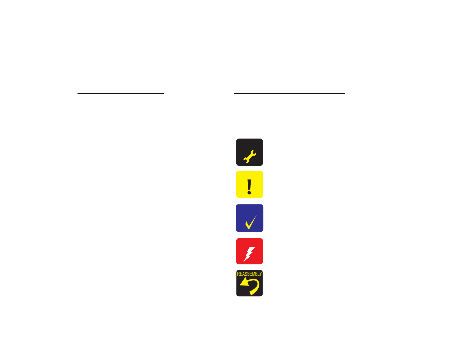
A D J U S T M E N T
R E Q U I R E D
C A U T I O N
C H E C K
P O I N T
W A R N I N G
Indicates an operating or maintenance procedure, practice or condition
that is necessary to keep the product’s quality.
Indicates an operating or maintenance procedure, practice, or condition
that, if not strictly observed, could result in damage to, or destruction of,
equipment.
May indicate an operating or maintenance procedure, practice or
condition that is necessary to accomplish a task efficiently. It may also
provide additional information that is related to a specific subject, or
comment on the results achieved through a previous action.
Indicates an operating or maintenance procedure, practice or condition
that, if not strictly observed, could result in injury or loss of life.
Provides helpful tips and cautions on reassembly procedures, especially
when incorrect reassembling may affect the print quality.
Page 5

General Precautions
To prevent possible accidents during maintenance work, strictly observe the servicing warnings and cautions described in this manual.
Power Supply
W A R N I N G
Before starting any service procedure, turn the printer power off and unplug the power cord from the wall outlet.
When the power supply cable must be connected, be aware of the potential for electrical shock and do all tasks by following the procedures in this
manual.
Do not touch any live parts unless instructed to do so.
Make sure to ground the printer properly. Otherwise a short circuit may cause an electric fire or shock.
Handle the power cable with care observing the precautions listed below.
• Do not plug too many leads into a single socket.
• Do not damage or tamper with the power cable.
• Avoid putting heavy objects on the cable, plucking it, and bending it forcedly. To do so may damage the cable and cause an electric fire and shock.
• Do not insert or remove the power cable with wet hands to prevent electric shock.
• Never replace the fuse on the Power Supply Board (high pressure/low pressure) under any circumstances.
Mechanical Components
W A R N I N G
When servicing any driving assembly (e.g., gears), turn the power off and unplug the power cord to prevent injuries.
Do not touch the driving part (e.g., gears) while the assembly (printer) is operating.
Page 6
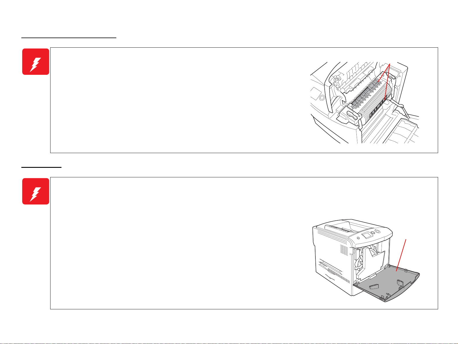
High Temperature Assembly
W A R N I N G
When working with hot parts (Fuser Unit etc.), turn the power off and unplug the power cord
Make sure to wait the hot section to cool enough especially when accessing near the section
Laser Beam
W A R N I N G
Understand hazardous nature of the laser beam, use extreme caution to avoid injury of yourself and anyone around you. Letting a laser beam get
HIGH
to prevent burns or injuries. After unplugging the power cable, wait until the part or unit
cools down before starting maintenance work.
immediately after printing.
directly into your eyes could result in loss of vision.
Since the laser beam has a narrower frequency band and more coherent phases than any other light (sunlight, electric light), the beam has excellent
monochromaticity and convergence, thus it reaches long distances. Because of these characteristics, the laser beam converges into one point, causing high
density and high temperature, which is harmful to the human bod y.
TEMPERATURE
00000101
Never turn the interlock switch on forcibly while servicing to prevent the laser beam from
emitting accidentally. The interlock switch is designed to be turned off when the cover D is
opened.
When performing maintenance work, be sure to turn the power off and unplug the power
cord.
If you need to work on the printer with power applied, strictly follow the instructions in this
manual.
Never disassemble the Laser Scanner Unit under any conditions.
Be sure to take off a wristw atch, ring or any ot her metal materials especially when working on
the printer with the power applied.
Cover D
00000201
Page 7

Handling Parts
W A R N I N G
Be careful not to throw out your back when handling heavy parts while taking care not to drop th ose parts.
Always wear gloves to perform maintenance work since the printer has many sharp edges.
Do not work with wet or oily hands, or may cause you to drop parts or affect the function of the printer.
Use only specified genuine parts for maintenance.
Do not repair or replace the ICs and other electrical components on the power circuit board (including fuse) under any circumstances.
Handling Consumables
W A R N I N G
To avoid dust explosion or ignition, never bring any consumables close to flame or throw them into fire.
Take extra care not to inhale the developing powder (such as toner), and get it into your mouth and eyes. Use extreme caution to avoid injury of yourself
and anyone around y ou.
Before starting your work, spread a sheet of paper over the working place to prevent interior of the product and the place becoming tainted.
If the developer or oil adheres to your skin or clothes, wipe it off thoroughly with dry rags before rinsing with water.
Do not disassemble the toner cartridges.
To prevent ignition, explosion, burn, injury, etc., do not use a general vacuum cleaner for
cleaning dropped toner. (To do so may cause the toner to catch fire by sparks in the vacuum
cleaner.)
Irregular Use of the Printer
W A R N I N G
Cautions when performing work with covers or parts removed
• As a general rule, do not power the printer while covers or parts are removed.
• If you need to remove covers or parts from the printer with power applied, take care o f yo ur fingers and clothes so as not to get entangled by moving
parts such as the driving belt, gears, and fans.
Altering the printer is banned under any circumstances.
00000301
Page 8

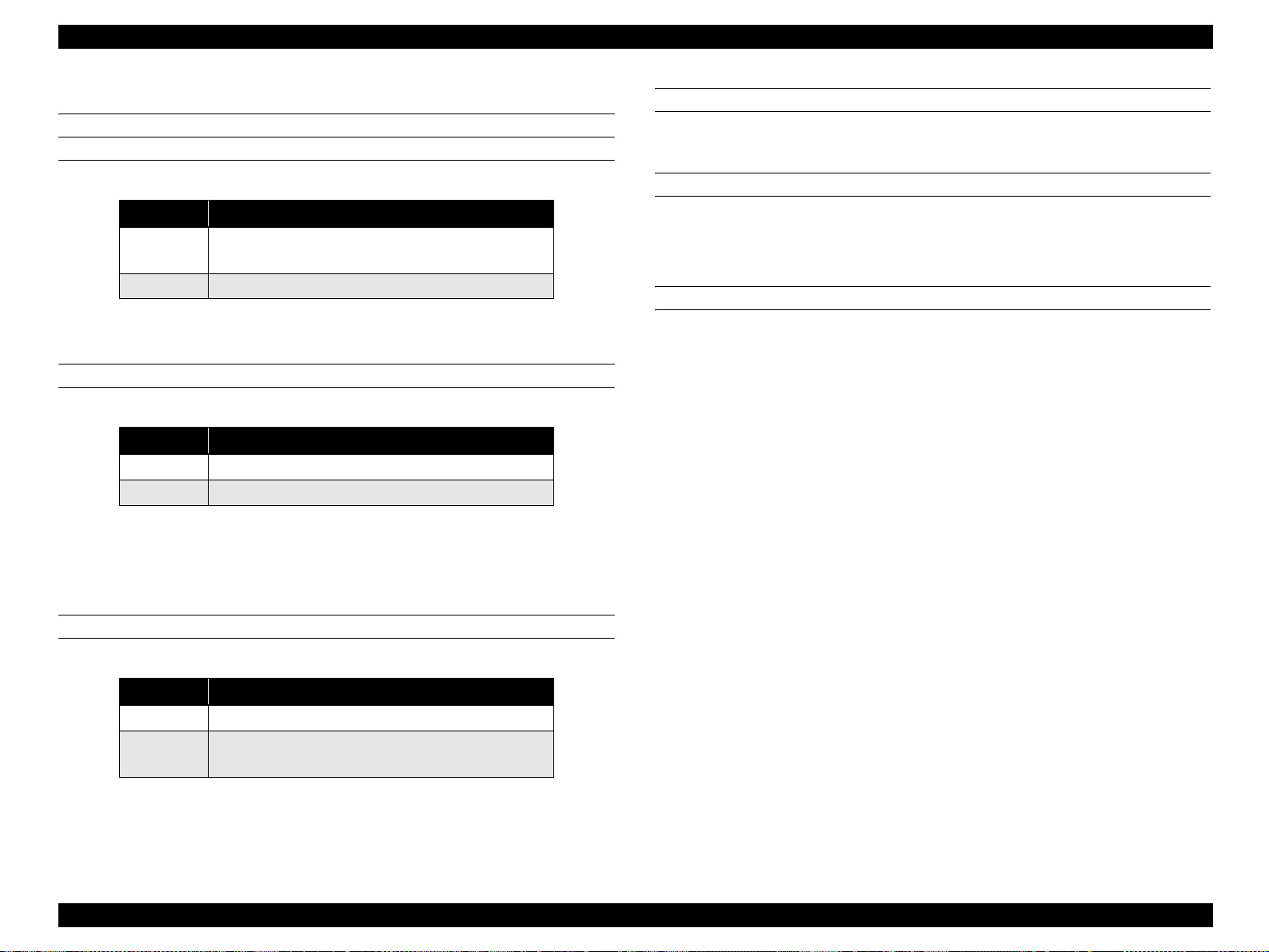
Revision Status
Revision Date of Issue Description
A APR. 28, 2005 First release
Page 9

EPSON AcuLaser C2600/2600 Revision A
Contents
Chapter 1 Product Description
1.1 Overview ............................................................................................................. 13
1.1.1 Engine Features .......................................................................................... 13
1.1.2 Controller Features..................................................................................... 13
1.1.3 Software Features ....................................................................................... 13
1.2 Basic Specifications............................................................................................ 14
1.2.1 Process Specifications & System................................................................ 14
1.2.2 Printer Basic Specifications ........................................................................ 14
1.3 Paper Specifications ............................................................................................ 22
1.3.1 Paper Type.................................................................................................. 22
1.3.2 Paper That May Cause Printing Defects, Paper Jams or Printer Malfunction.
22
1.3.3 Paper Feed Types........................................................................................ 23
1.3.4 Printing Area............................................................................................... 23
1.4 Reliability and Serviceability.............................................................................. 24
1.4.1 Reliability ................................................................................................... 24
1.4.2 Durability.................................................................................................... 25
1.4.3 Serviceability.............................................................................................. 25
1.5 Service Conditions............................................................................................... 26
1.5.1 Space Requirements.................................................................................... 26
1.6 Conditions for Storage and Transport ................................................................. 27
1.7 Electrical Characteristics..................................................................................... 28
1.8 Compatible Specification .................................................................................... 29
1.9 Consumables/Periodic Replacement Unit........................................................... 30
1.9.1 Specifications.............................................................................................. 30
1.9.2 Conditions for Storage and Transport......................................................... 31
1.10 Maintenance ...................................................................................................... 32
1.11 External Appearance and Unit Names.............................................................. 33
1.11.1 Unit Names............................................................................................... 33
1.12 Engine Restrictions............................................................................................ 34
1.12.1 Factors Limiting Printing Speed............................................................... 34
1.12.2 Toner Duty Limiting Value...................................................................... 34
1.13 Notes When Replacing Consumables and Installing Optional Products .......... 35
1.13.1 Consumables............................................................................................. 35
1.13.2 Options...................................................................................................... 35
1.14 Notes on Fuser Pressure.................................................................................... 35
1.15 Life Details........................................................................................................ 36
1.16 Controller Specifications................................................................................... 40
1.16.1 Controller Basic Specifications................................................................ 40
1.16.2 Controller Configuration.......................................................................... 40
1.16.3 External Interface Specifications.............................................................. 41
1.17 Control Panel..................................................................................................... 43
1.17.1 External Appearance and Names.............................................................. 43
1.17.2 Panel Settings List.................................................................................... 45
1.17.3 Explanation of Menu and Settings............................................................ 56
1.17.4 Special Operations.................................................................................... 58
1.18 Printer Status..................................................................................................... 59
1.18.1 List of Printer Messages........................................................................... 59
1.18.2 Status Messages and Troubleshooting...................................................... 61
1.18.3 Warning Messages and Troubleshooting ................................................. 61
1.18.4 Error Messages and Troubleshooting....................................................... 62
1.18.5 Help Messages.......................................................................................... 65
1.18.6 Service Call Error Messages..................................................................... 71
1.19 Expanding the RAM.......................................................................................... 73
1.20 Handling Precautions ........................................................................................ 73
1.20.1 Precautions When Turning Off the Power ............................................... 73
1.20.2 Precautions for High Temperature Parts .................................................. 73
1.21 Status Sheet....................................................................................................... 74
1.22 Engine Status Sheet........................................................................................... 77
1.23 Paper Handling Algorithm................................................................................ 78
1.24 Toner Check Sheet............................................................................................ 79
1.24.1 For Color Mode........................................................................................ 79
1.24.2 For 4xB/W Mode...................................................................................... 79
1.25 Form Overlay List............................................................................................. 80
9
Page 10

EPSON AcuLaser C2600/2600 Revision A
1.26 Switching between Color Mode and Monochrome Mode ................................ 81
1.26.1 Switching of Operation Mode .................................................................. 81
1.26.2 Switching of Printer Driver ...................................................................... 84
Chapter 2 Operating Principle
2.1 Print Process........................................................................................................ 86
2.1.1 Print Process Overview............................................................................... 86
2.1.2 Print Process Diagram ................................................................................ 87
2.1.3 Technical Explanation of Print Process...................................................... 88
2.2 Paper Feed Mechanism...................................................................................... 104
2.2.1 Main Unit Paper Feed Mechanism........................................................... 105
2.2.2 Duplex Printing......................................................................................... 110
2.2.3 Paper Feed from Opt. Feeder Unit............................................................ 111
2.3 Drive................................................................................................................. 112
2.3.1 Main Drive Motor..................................................................................... 113
2.3.2 Photoconductor Drive Motor.................................................................... 115
2.3.3 Rotary Drive Motor.................................................................................. 115
2.3.4 Development Drive Motor........................................................................ 116
2.3.5 Duplex Motor............................................................................................ 117
2.3.6 Opt. Feeder Motor .................................................................................... 118
2.4 Electrical............................................................................................................ 119
2.4.1 Electronic Circuit Board / R/W Module................................................... 119
2.4.2 Motor........................................................................................................ 120
2.4.3 Solenoids and Clutches............................................................................. 121
2.4.4 Sensors and Switches................................................................................ 122
2.4.5 Interlock Switch........................................................................................ 123
2.4.6 Fan ............................................................................................................ 124
2.5 Control............................................................................................................... 125
2.5.1 Hardware for Control................................................................................ 125
2.5.2 Image-Stabilizing Control ........................................................................ 126
2.5.3 Operation Sequence.................................................................................. 131
2.5.4 Operating Mode........................................................................................ 133
2.5.5 Control of Consumables and Components Needing Periodic Replacement ...
134
2.6 Electrical Circuit Operation Principle............................................................... 136
2.6.1 Electric Circuit.......................................................................................... 136
2.6.2 Engine Control Circuit.............................................................................. 138
2.6.3 Controller.................................................................................................. 140
Chapter 3 Troubleshooting
3.1 Overview................... ...... ................................. ...... .................................. ...... ... 142
3.1.1 Procedure Outline for Troubleshooting.................................................... 142
3.1.2 Preliminary Check.................................................................................... 142
3.1.3 Precautions in Performing Troubleshooting Work................................... 143
3.1.4 Procedure for Troubleshooting................................................................. 143
3.2 Troubleshooting for Paper Jam ......................................................................... 144
3.3 Troubleshooting According to the Error Message............................................ 145
3.3.1 List of Error Message............................................................................... 145
3.3.2 List of Service Request............................................................................. 145
3.3.3 Troubleshooting for Error Message.......................................................... 147
3.3.4 Troubleshooting for Service Request Error.............................................. 157
3.4 Printing-quality troubleshooting (PQT) ............................................................ 184
3.4.1 Print Quality Trouble List......................................................................... 184
3.4.2 Printing-quality troubleshooting............................................................... 186
3.5 Test Print........................................................................................................... 208
Chapter 4 Disassembly and Assembly
4.1 Overview................... ...... ................................. ...... .................................. ...... ... 211
4.1.1 Precautions................................................................................................ 212
4.1.2 Prohibited Disassembly............................................................................ 214
4.1.3 Tools......................................................................................................... 215
4.1.4 Inspection After Assembling .................................................................... 215
4.2 Procedures for Disassembly and Assembly ...................................................... 216
4.3 Disassembly and Reassembly ........................................... ...... ...... .................... 217
4.4 Disassembling Flowchart.................................................................................. 219
4.5 Disassembling/Assembling the Main Unit........................................................ 234
4.5.1 Consumables............................................................................................. 234
4.5.2 Housing..................................................................................................... 240
4.5.3 Paper Transport......................................................................................... 253
4.5.4 Xerographic.............................................................................................. 263
4.5.5 Exposure................................................................................................... 268
4.5.6 Deve.......................................................................................................... 271
4.5.7 Transfer..................................................................................................... 276
4.5.8 Fusing....................................................................................................... 293
4.5.9 Drive......................................................................................................... 294
4.5.10 Electrical................................................................................................. 307
10
Page 11

EPSON AcuLaser C2600/2600 Revision A
4.5.11 MP Tray.................................................................................................. 323
4.5.12 Paper Cassette......................................................................................... 339
4.6 Disassembling/Assembling the Options............................................................ 342
4.6.1 Opt. Feeder ............................................................................................... 342
4.6.2 Duplex Unit .............................................................................................. 355
Chapter 5 Adjustment
5.1 Overview ........................................................................................................... 365
5.1.1 Precautions................................................................................................ 365
5.1.2 Reference Chapter .................................................................................... 365
5.1.3 Adjustment Execution Timing.................................................................. 366
5.2 Adjustment Program (LPssp)............................................................................ 367
5.2.1 Overview................................................................................................... 367
5.2.2 Setup before Adjustment.......................................................................... 367
5.2.3 Writing the model name........................................................................... 370
5.2.4 Writing USB ID........................................................................................ 371
5.2.5 Counter Reset............................................................................................ 372
5.2.6 Timing Adjustment................................................................................... 373
5.2.7 Registration Adjustment (Top)................................................................. 374
5.2.8 Registration Adjustment (Side)................................................................ 375
5.2.9 2nd Transfer Bias Adjustment.................................................................. 376
5.2.10 Vpp Setting............................................................................................. 377
5.3 Firmware Update............................................................................................... 378
5.3.1 Main Controller Firmware Update........................................................... 379
5.3.2 Engine Controller Firmware Update ........................................................ 381
6.5.2 Regular Replacement Parts....................................................................... 397
6.6 Gluing/Lubrication....................................................... ..... ................................ 398
6.6.1 Gluing....................................................................................................... 398
6.6.2 Lubrication................................................................................................ 398
Chapter 7 APPENDIX
7.1 Connector Summary.......................................................................................... 411
7.1.1 Connectors and Plug and Jack Layout...................................................... 411
7.2 Wiring Connection Diagrams....................................... .................................. ... 418
7.3 Parts List............................................................................................................ 433
7.4 Exploded Diagrams........................................................................................... 437
7.5 Circuit Diagrams............................................................................................... 449
Chapter 6 Maintenance
6.1 Overview ........................................................................................................... 385
6.2 Cleaning............................................................................................................. 387
6.3 Maintenance Menu............................................................................................ 389
6.3.1 Entry into Maintenance Mode.................................................................. 389
6.3.2 Maintenance Menu Items ......................................................................... 390
6.4 Sheet for Servicing............................................................................................ 391
6.4.1 Engine Status Sheet.................................................................................. 391
6.4.2 Print Log Report....................................................................................... 394
6.5 Consumables and Components That Need Periodic Replacement.................... 396
6.5.1 Consumables............................................................................................. 396
11
Page 12

PRODUCT DESCRIPTION
CHAPTER
1
Page 13
EPSON AcuLaser C2600/2600 Revision A
1.1 Overview
This printer is a non-impact color page printer that takes advantage of a laser and
electrophotographic technologies.
It provides 600 dpi of resolution and 7.5 ppm (A4, color printing) or 30 ppm (A4,
monochrome printing) of print speed.
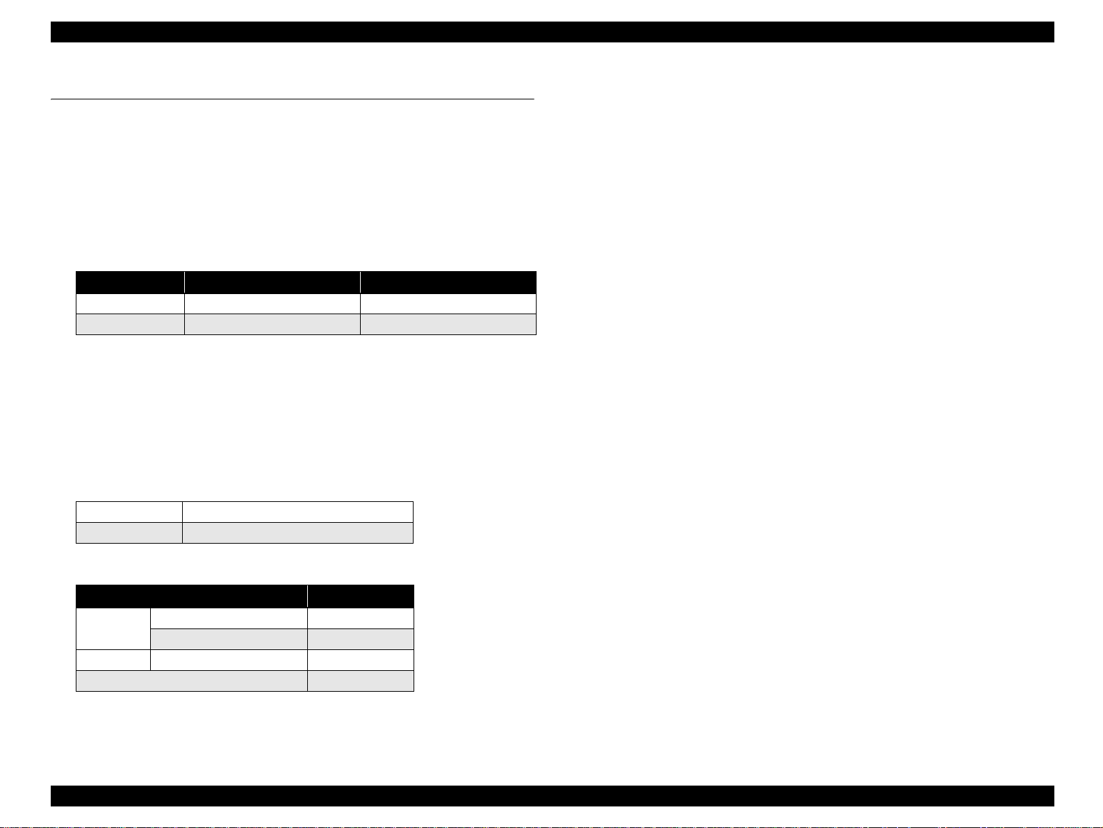
1.1.1 Engine Features
High speed 4-cycle A4 engine
Table 1-1. Print Speed (When Printing A4)
Color printing Monochrome printing
Simplex printing 7.5 ppm 30 ppm
Duplex printing 7.5 ppm 20 ppm
Two models: color and monochrome
The monochrome model has one black toner cartridge bundled as standard.
Adding three black toner cartridges (option) allows the printer to print up to
20,000 copies. Furthermore, the monochrome model can be upgraded to color
model.
The color model can be operated as monochrome model by replacing the color
toners with black ones or removing them.
Compact and light weight, suitable for desktop placement
Dimension 435 mm (W) x 516 mm (D) x 425 mm (H)
Weight 35 kg
Paper supply (Maximum of 1150 sheets, 3-bin paper feed is possible)
1.1.2 Controller Features
High speed intelligent controller
CPU: VR5532A (350 MHz)
RAM
Standard RAM: 64 MB
Expanded RAM: 512 MB (When two 256 MB DIMMs are installed.)
Support for optional large capacity, 40 GB HDD.
Color technology
nPGI, which allows low price, high quality printing
Wide LCD panel with backlight
The new wide LCD panel supp orting a max imum of 2 2 digits a nd 5 lines (132 x 65
dots) provides improved operation and visibility.
Improved serviceability with the addition of the Help function (with description
and graphics).
Interface
USB interface (Rev. 2.0 HS, Supports bi-directional (D4))
Network interface (10Base-T/100Base-TX)
Parallel interface (IEEE1284)
Type-B interface
1.1.3 Software Features
Adobe PostScript 3 (17 fonts), PCL6 (monochrome) as standard
ESC/Page Color, PCL5e, FX, LQ, and IBM emulations are also provided
Paper cassette
Standard
Option Paper cassette unit 500 sheets
MP Tray 150 sheets
Lower paper cass et t e 500 sheets
Maximum 1150 sheets
Paper eject capacity is 250 sheets, face-down only.
Printer status and printer environment monitor with use of bi-directional EJL and
MIB
Version upgrade function for engine program ROM
Support for DCC command (DIAG command only)
Support for firmware overwrite using RCC (full or partial overwrite)
Support for manual duplex
Product Description Overview 13
Page 14

EPSON AcuLaser C2600/2600 Revision A
1.2 Basic Specifications
1.2.1 Process Specifications & System
Printing method: Semiconductor laser beam scan and
electrophotography with dry single component system.
Exposure light source: Semiconductor laser
Photoconductor: Organic photoconductor
Charging: Wire electrode scorotron
Development: 1-component non-contact development system
Toner: 1-component non-magnetic toner
Primary transfer: Intermediate transfer belt method
Fixing: Roller heat fixing system
1.2.2 Printer Basic Specifications
RESOLUTION
600 x 600 dpi
WARMING UP TIME
120 V: 80 seconds or less (at 23 °C, 55 % RH, rated voltage)
230 V: 80 seconds or less (at 23 °C, 55 % RH, rated voltage)
OPERATION MODE
This engine supports the following operation modes.
B/W mode: Supports Toner cartridge K x 1
4xB/W mode: Supports Toner cartridge K x 4
Color mode: Supports Toner cartridges Y x 1, M x 1, C x 1, and K x 1.
PRINT MODE
Color mode: Color mode using Y, M, C, K toner (color mode only)
Monochrome mode: Normal black and white mode, enabling printing at the
highest speed of the main unit.
PRINTING SPEED MODE
Std. mode (plain paper 1): Makes prints at the maximum speed of the engine.
Std. mode (plain paper 2): This mode is to make prints on papers with less
fixability (such as bond papers) at the maximum speed
of the engine. As the fuser unit takes a substantial
amount of time to increase its temperature for fixing
toner onto the papers firmly, the first print time
becomes slow. When it comes to a continuous printing,
however, the printing can be performed at the
maximum speed of the engine.
Low speed mode 1: Slows down the speed of printing on papers with
thickness of 90 g/m
fixability.
2
(24 lb) or more to sustain the
Low speed mode 2: Slows down the speed of printing on envelopes for the
better fixability or on transparents for the stable
permeability.
Product Description Basic Specifications 14
Page 15
EPSON AcuLaser C2600/2600 Revision A
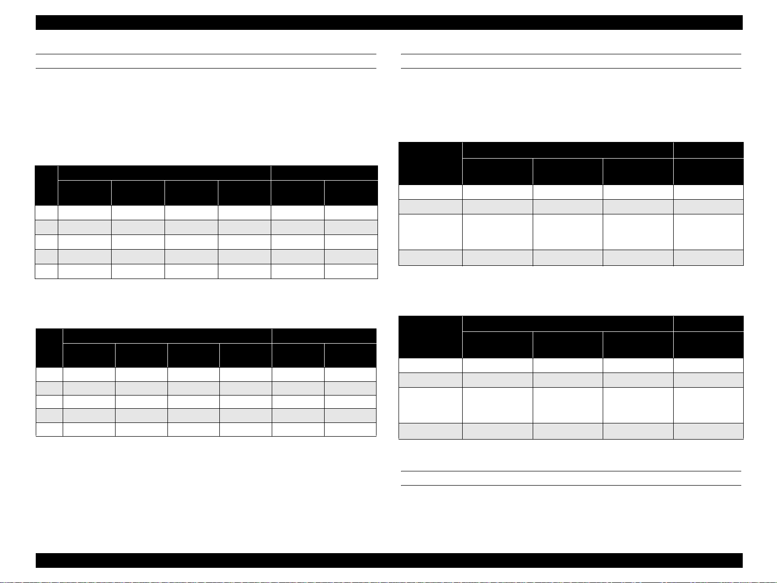
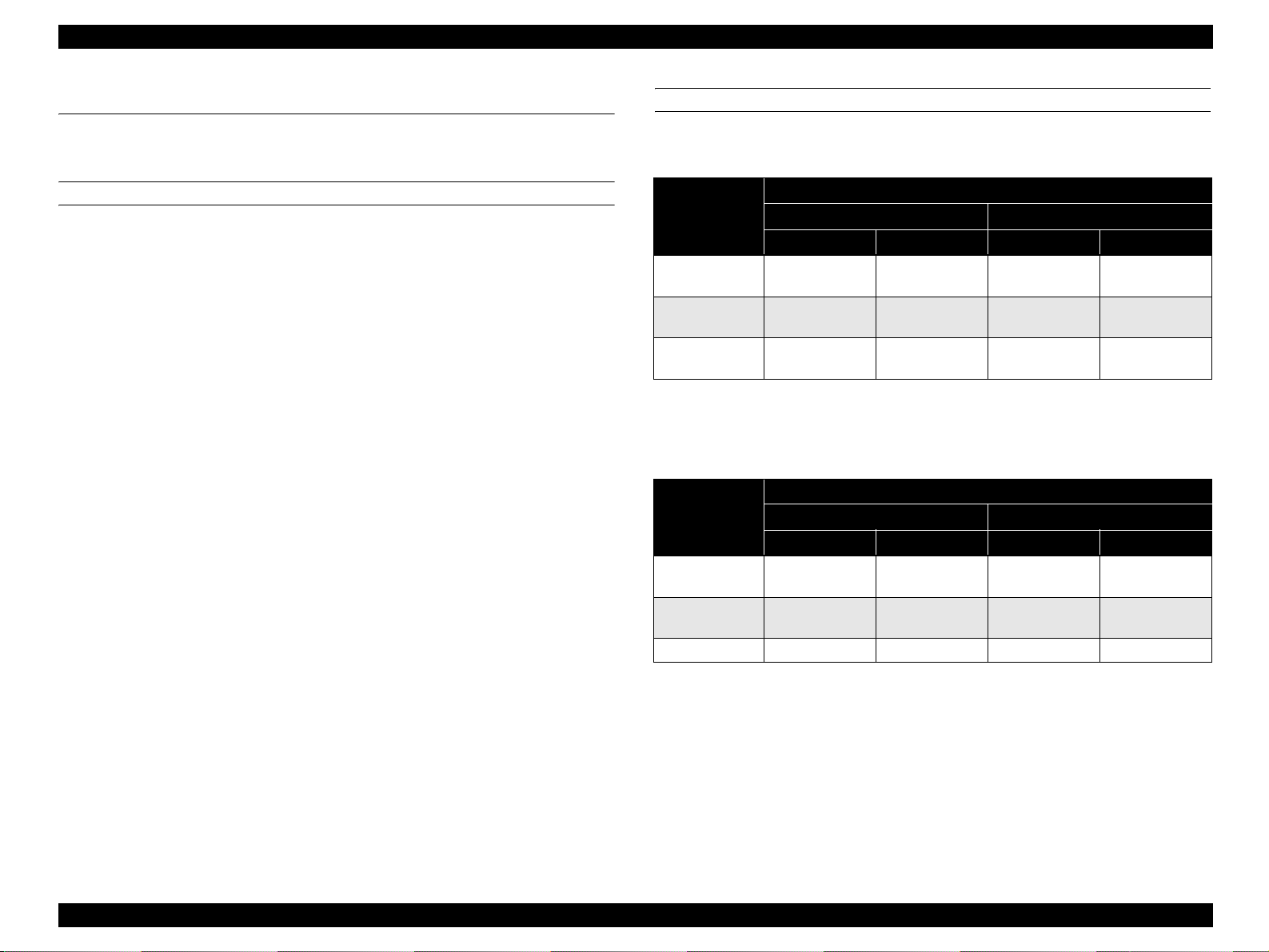
FIRST PRINT TIME
The following table shows the time from receiving a start command to when trailing
edge of the paper leaves the paper eject roller. Note that the time given in the tables
does not apply when the printer is in the conditions described in “1.12 Engine
Restrictions” (p.34).
Monochrome mode*
1
Table 1-2. Monochrome Mode (Unit: Seconds or Less)
Paper
size
A4
A5
B5
LT
EXE
Std. mode
(Plain paper 1)
9.3 19.3 17.9 26.6 13.3 23.3
8.9 18.9 17.1 25.0 12.9 22.9
9.1 19.1 17.6 25.9 13.1 23.1
9.2 19.2 17.8 26.3 13.2 23.2
9.2 19.2 17.7 26.1 13.2 23.2
Color mode*
1
Simplex printing Duplex printing
Std. mode
(Plain paper 2*2)
Low speed
mode 1
Low speed
mode 2
Std. mode
(Plain paper 1)
Std. mode
(Plain paper 2*2)
Table 1-3. Color Mode (Unit: Seconds or Less)
Paper
EXE 15.2 25.2 23.7 32.1 23.2 33.2
Std. mode
size
(Plain paper 1)
A4 15.3 25.3 23.9 32.6 23.3 33.3
A5 14.9 24.9 23.1 31.0 22.9 32.9
B5 15.1 25.1 23.6 31.9 23.1 33.1
LT 15.2 25.2 23.8 32.3 23.2 33.2
Simplex printing Duplex printing
Std. mode
(Plain paper 2*2)
Low speed
mode 1
Low speed
mode 2
Std. mode
(Plain paper 1)
Std. mode
(Plain paper 2*2)
CONTINUOUS PRINTING SPEED
This excludes operations that fall under the restrictions on printing speed explained in
“1.12 Engine Restrictions” (p.34).
Monochrome mode
Table 1-4. Monochrome Mode (Unit: PPM)
Simplex printing Duplex printing
Paper size
A4, B5, LT 30 4.2 2.6 20
A5, EXE 30 4.2 2.6 20
Envelope C6,
MON, DL, C5,
Com-#10
User define d s i z e 30
Std. mode
(Plain paper 1, 2)
––2.6–
Low speed mode 1 Low speed mode 2
4.2 2.6
Std. mode
(Plain paper 1, 2)
–
Color mode
Table 1-5. Color Mode (Unit: PPM)
Simplex printing Duplex printing
Paper size
A4, B5, LT 7.5 2.9 2.1 7.5
A5, EXE 7.5 2.9 2.1 7.5
Envelope C6,
MON, DL, C5,
Com-#10
User define d s i z e 7.5 2.9
Std. mode
(Plain paper 1, 2)
––2.1–
Low speed mode 1 Low speed mode 2
2.1
Std. mode
(Plain paper 1, 2)
–
Note *1: The above speed are the same for any paper feeder including the option cassette.
*2 : The mode to be used for papers that are hardly fixed.
As the temperature for the f ixation is set h igher than that o f the other modes , it takes relati v ely
long period of time until the t em p. rea ches the required level.
PAPER FEED REFERENCE
Center-line reference for each paper size and for both MP tray and 500-sheet cassette
(optional).
Product Description Basic Specifications 15
Page 16
EPSON AcuLaser C2600/2600 Revision A
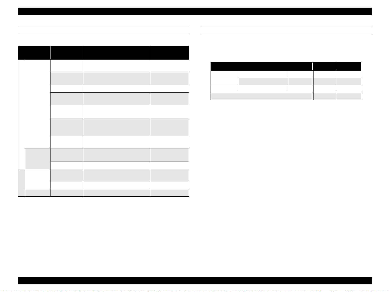
PAPER FEED
Table 1-6. Paper Feed
Paper feed
Sheet capacity
Height capacity
150 sheets
16.5 mm
Paper type/Paper size
Standard paper:
EPSON high quality plain paper
Plain paper/recycled paper:
A4, A5, B5, LT, GLT, HLT, EXE
60 sheets Transparency: A4, LT –
50 sheets
MP tray
75 sheets
Standard
15 sheets
Labels: A4, LT
EPSON coated papers: A4
Thick Paper:
A4, A5, B5, LT, GLT, HLT, EXE
Envelopes:
C5, C6, Com-#10, DL, Monarch,
ISO-B5
User defined size:
Width 98 to 216/ Length 148 to 297
Standard paper:
EPSON high quality plain paper
Standard paper:
EPSON high quality plain paper
Lower paper
cassette (C1)
Paper
cassette unit
(C2)
Option
16.5 mm
500 sheets
55 mm Plain paper: A4, L T 64 to 90 g/m
500 sheets
55 mm Plain paper: A4, L T 64 to 90 g/m
Duplex – A4, LT, B5, A5, EXE 64 to 90 g/m
Note *: Refer to “1.3 Paper Specifications” (p.22).
Acceptable paper
basis weight*
64 to 90 g/m
91 to 163 g/m
64 to 163 g/m
82 g/m
–
–
82 g/m
82 g/m
OPTIONAL PAPER SOURCE COMBINATION
Installing an optional paper cassette unit enables the printer to load the maximum
number of papers as shown in the table below.
Table 1-7. Optional Paper Source Combination
2
2
Standard
Option Paper cassette unit (C2) 500 sheets* – {
Note *: Standard pa per: EPSON high quality plain paper (82 g/m2)
2
2
2
2
2
2
2
Combination (1) (2)
MP tray 150 sheets* {{
Lower paper cassette (C1) 500 sheets* { {
Total number of sheet s 650 sheets 1150 sheets
Product Description Basic Specifications 16
Page 17
EPSON AcuLaser C2600/2600 Revision A
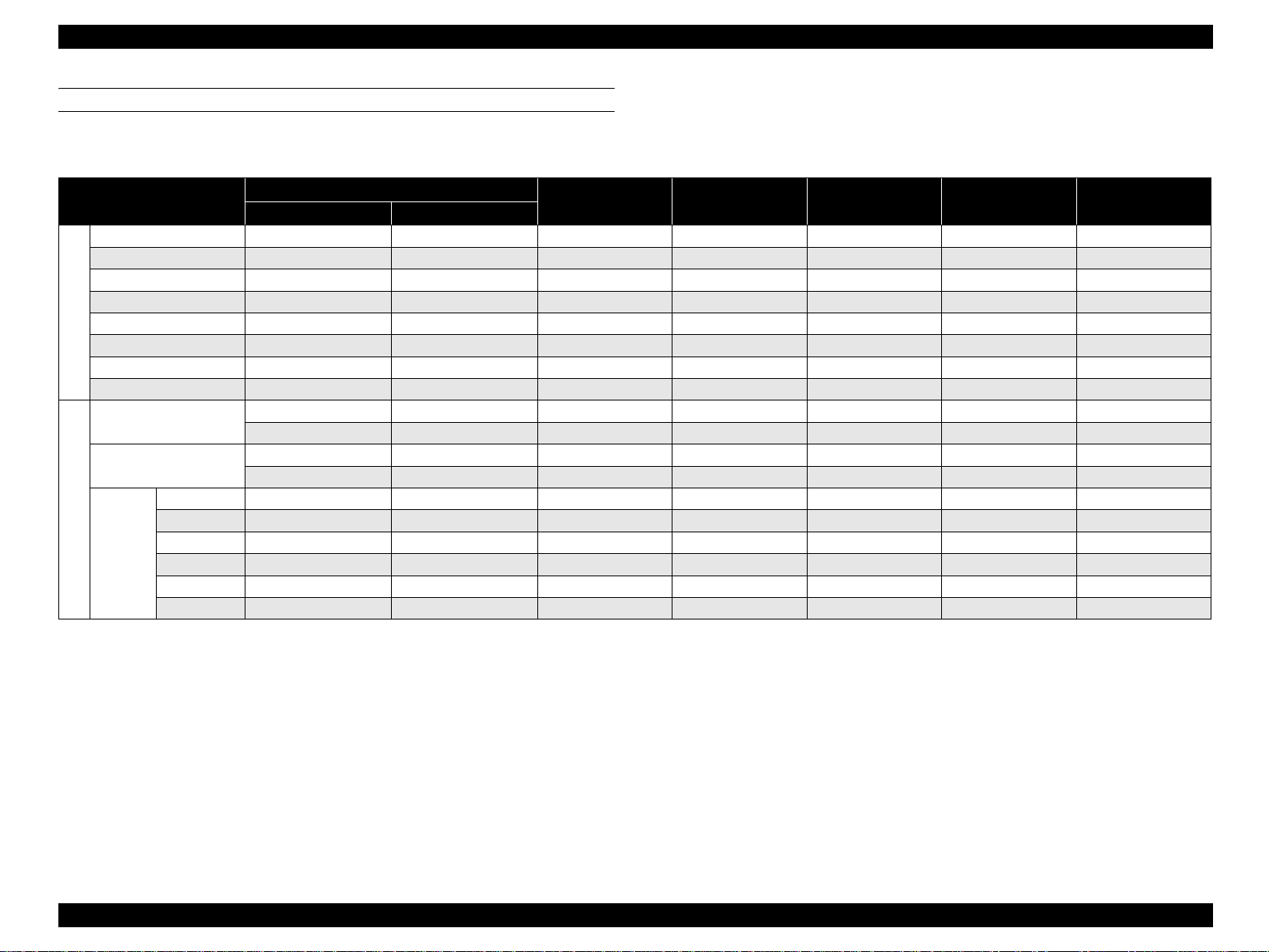
SUPPORTED PAPER SIZE, TYPE AND ORIENTATION
Supported paper
Table 1-8. List of Supported Paper Size, Type and Orientation
Paper
A4 297.00 210.00 {{{SEF {
A5 210.00 148.00 { – – SEF {
JIS-B5 257.00 182.00 { ––SEF{
LT 279.40 (11.00") 215.90 (8.50") { { { SEF {
HLT 215.90 (8.50") 139.70 (5.50") { ––SEF–
Standard
GLT 266.70 (10.50") 203.20 (8.00") { – – SEF –
EXE 266.70 (10.50") 184.15 (7.25") { ––SEF{
User defined pa p er s ize 148.00 to 297.00 98.00 to 216.00 { – – Free –
Transparency
Labels
MONARCH 190.50 (7 1/2) 98.43 (3 7/8) { ––SEF–
Com-#10 241.30 (9 1/2) 104.78 (4 1/8) { – – SEF –
Special paper
DL 220.00 110.00 { ––SEF–
C5 229.00 162.00 { – – SEF –
Envelopes
C6 162.00 114.00 { ––SEF–
ISO-B5 250.00 176.00 { – – SEF –
Paper size Dimensions in mm (inches)
Vertical (length) Horizontal (width)
A4: 297.00 A4: 210.00 { ––SEF–
LT: 279.40 LT: 215.90 { – – SEF –
A4: 297.00 A4: 210.00 { ––SEF–
LT: 279.40 LT: 215.90 { – – SEF –
MP tray
Standard lower
paper cassette
Optional pape r
cassette unit
Paper orientation Duplex printing
Note 1: SEF (Short Edge Feed): Set paper to be loaded from its short side.
2: The supported sizes differ depending on the destination.
3: For the orientation of envelopes, refer to
4: Curls must be straightened.
“Envelope orientation” (p.18).
Product Description Basic Specifications 17
Page 18
EPSON AcuLaser C2600/2600 Revision A
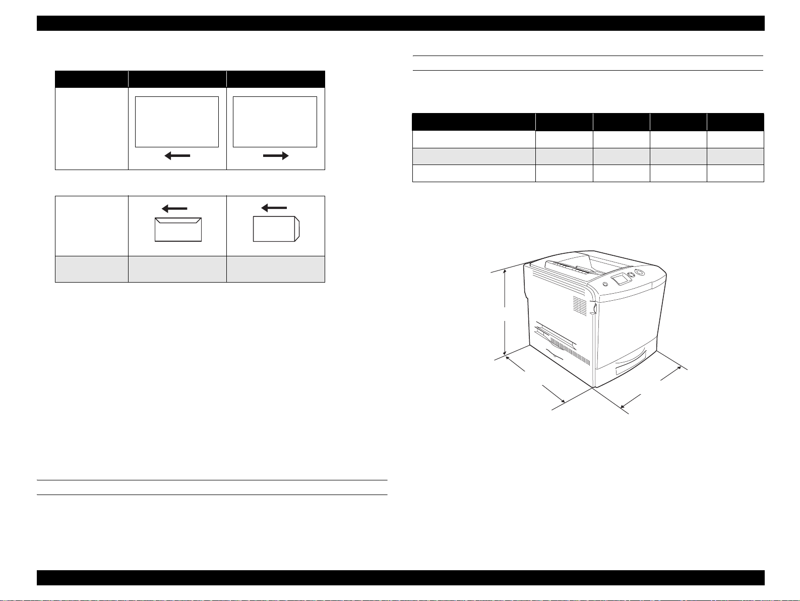
Paper orientation
Paper Feed MP Tray Cassette (C1/C2)
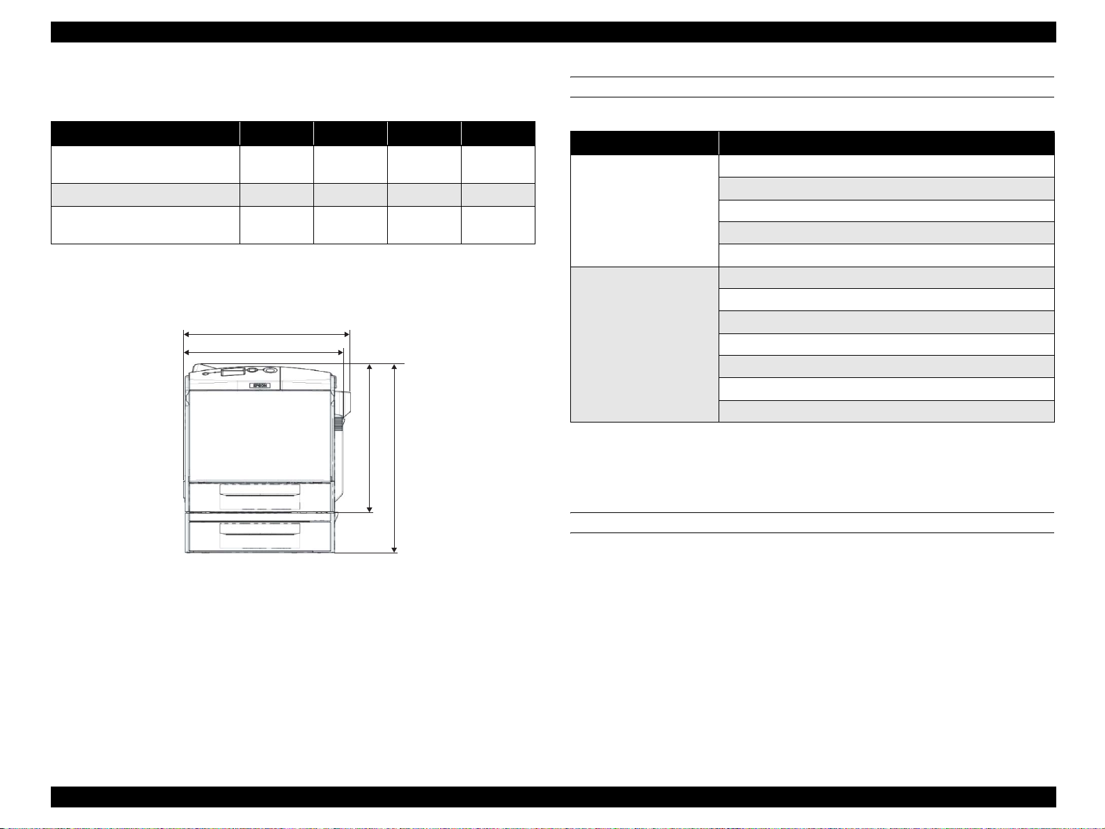
DIMENSIONS AND WEIGHT
Stand alone outline dimensions and weight
Table 1-9. Stand Al one Outline Di m e ns i ons and Weight
Paper Orientation/
Feeding Direction
Place Print Side Down. Place Print Side Up.
Width (mm) Depth (mm) Heigh t (mm) Weight (kg)
Main unit 431 518 425
500-sheet cassette unit (option)
Duplex unit (option)
408 482 140 5
132 282 220 0.9
37*1 / 33*
Envelope orientation
Note : Ma nufacturing tolerance is ± 5 mm in dimensions and ± 0.5 kg in weight.
Note *1: Includes consumables.
Feeding Direction
*2 : Initial condition (exc. Toner Cartridges)
2
01000201
C5
Envelope Types
01000101
MONARCH, DL,
Com- #10, C6
NOTE 1: Place papers in the MP tray with the printable side face down.
2: When the flap is closed, printing on the reverse (flap side) is not
available.
(The flap may adhere to the transfer belt and open, which may
result in paper wrinkles and paper jams.)
3: O nly envelop es without tape or glue can be used.
4: Change the fuser unit lever when printing envelopes.
(For details, refer to “1.14 Notes on Fuser Pressure” (p.35).)
5: Only envelopes with trapezoid shaped flaps can be fed with the
flap opened.
Envelopes with triangular shaped flaps should not be used. (It
may cause a slip off or stack defect.)
PAPER EJECT
Only for face-down (FD) 250 sheets
NOTE: Standard paper: EPSON high quality plain paper (82 g/m
2
)
425 mm
518 mm
431 mm
01000301
Figure 1-1. Dimensions (Main Unit)
Product Description Basic Specifications 18
Page 19
EPSON AcuLaser C2600/2600 Revision A
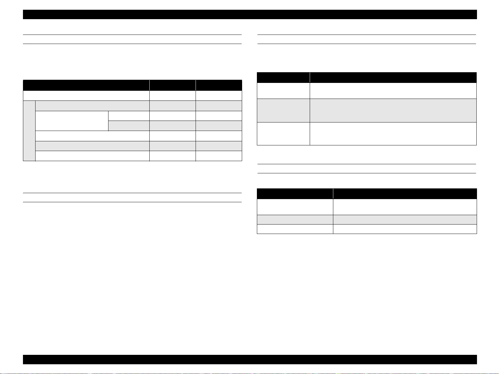
Outline dimensions and weight with options installed
Table 1-10. Outline Dimensions and Weight With Opti ons Installed
Width (mm) Depth (mm) Height (mm) Weight (kg)
Main unit + Optional paper cassette
unit
Main unit + Duplex unit
Main unit + Optional paper cassette
unit + Duplex unit
Note : Manufacturing tolerance is ± 5 mm in dimensions and ± 0.5 kg in wei ght.
Note *: Includes consumables.
431 518 538
447 518 425 38*
447 518 538 43*
447 mm
431 mm
42*
CONSUMABLES AND PERIODIC REPLACEMENT UNIT
Table 1-11. List of Consumables and Periodic Replacement Unit
Classification Replacement unit
Toner cartridge (Black, Cyan, Yellow, Magenta)
Photoconductor un it
Consumables
Periodic replacement units
Fuser unit
Waste toner collector
Filter
Transfer belt unit (TRANSFER, Assy; ASP)
Cleaning tape (MOUNTING PLATE, ANTI-STATIC; ASP)
Cleaner clutch (CLUTCH, CLEANER)
2nd transfer clutch (CLUTCH, 2ND TRANSFER)
Paper eject roller (COVER Assy., FU; ASP)
Post-fixing roller (COVER Assy., FU; ASP)
Pickup roller (ROLLER ASSY, PICK UP)
425 mm
538 mm
Replacement Unit” (p.30).
POWER SUPPLY
Power supply operating voltage/frequency
NOTE: For detailed specifica tions, refer to “1.9 Consumables/P eri od ic
01000401
Figure 1-2. Dimensions (Including Options)
AC 110 V to 120 V ± 10 %, 50 Hz / 60 Hz ± 3 Hz
AC 220 V to 240 V ± 10 %, 50 Hz / 60 Hz ± 3 Hz
Power supply for the controller
DC 5.0 V ± 5 %, 2A
DC 3.3 V ± 5 %, 5A
Product Description Basic Specifications 19
Page 20
EPSON AcuLaser C2600/2600 Revision A
POWER CONSUMPTION
The maximum rated current is measured with all engine options and controller options
installed.
Table 1-12. List of Power Consumption
120V 230V
Maximum rated curr ent 10 A or less 6 A or less
Maximum 880 W 900 W
Continuous printing average
Average during standby with the heater on 96 W 99 W
Sleep mode* 10 W or less 12 W or less
Power consumption
Power supply off 0 W 0 W
Note *: Refer to “Table 1-13. Operating State” (p.20).
Color 335 W 332 W
Monochrome 567 W 583 W
CONSUMPTION CURRENT
500-sheet cassette unit (op tion)
5 V / 0.3 A or less
24 V / 0.35 A or less
Du plex unit (option)
5 V / 0.1 A or less
24 V / 1.0 A or le ss
OPERATING STATE
This printer operates in the following 3 operating states.
Table 1-13. Operating State
Operational mode Explanation
Operating state
Standby state
Sleep state
Performs a print job in va rious printi ng mode upon receiv ing a comma nd
from the controller.
Standby state. Switches to this mode auto matic a lly after comp le tin g a
print job (exits out of the operating state) without receiving any
commands.
Switches to this mode on receiving a comman d from the con trol le r.
Supporting BAM and International Energy Star Program (power
consumption 21W or less within 30 minutes after the printing operation)
PRODUCT LIFETIME
Table 1-14. Product Lifetime
Product lifetime
1
Main unit
Optional paper cassette unit 400,000 pages*
Duplex unit 600,000 pages*
Note *1: 1,200,000 pages for single color images
*2: 480,000 pages when the ratio of color and monochr ome is 1:1 (1,200,000 images)
*3: 2/3 of the main unit max pages (Monochrome 600,000 pages)
*4: When all of the main unit m a x pages (Monochrome 600,000 pages) are made by
duplexing.
300,000 pages (color*
5 years; whichever comes first.
) or 600,000 pages (monochrome)*2 or
3
4
Product Description Basic Specifications 20
Page 21
EPSON AcuLaser C2600/2600 Revision A
NOISE
Sound pressure
Table 1-15. Sound Pressure
Operating state Standby state Sleep state
Main unit
Note : Reference values
Color mode 56 dB (A) 40 dB (A)
Monochrome mode 56 dB (A) 40 dB (A)
Background noise
Sound power
Table 1-16. Sound Power
Operating state Standby state Sleep state
Main unit
With all optional installations
(reference value)
Note *: The method of measu ring and calculation conforms to ISO-7779 and ISO-9296.
Color mode 68 dB (A)* 52 dB (A)
Monochrome mode 66 dB (A)* 52 dB (A)
Exceeds the main
unit values by less
than 1 db
(Employing standard values for RAL-UZ85 (BAM standard))
52 dB (A)
Background noise
Note : (A) indicates that the valu e has be en adju sted with c on side ra tio n of hu ma n sen sitiv ity
to frequencies (correction by A characteristic).
EXHAUST GAS
Table 1-17. Exhaust Gas
Value
3
Ozone Concentration 0.02 mg/m
Styrene Concentration 0.07 mg/m3 or less (the measurin g me thod conforms to BAM)
Fine Particles Concentration 0.075 mg/m
TVOC 0.40 mg/m3 or less
or less (the measurin g me thod conforms to BAM)
3
or less (the measuring met hod conforms to BAM)
Product Description Basic Specifications 21
Page 22

EPSON AcuLaser C2600/2600 Revision A
1.3 Paper Specifications
1.3.1 Paper Type
Standard paper
RX-80 paper (Monochrome), 4024 paper (20 lb) (Monochrome),
EPSON high quality plain paper (A4)
Plain paper
64 g/m
Recommended recycled paper: Recommended Recycling Copy classic
Special paper
EPSON transparency sheets (A4, LT)
Labels
Thick papers (91 g/m
Envelopes (75 g/m
EPSON coated papers (A4) (Guarantees only the paper feedability)
C H E C K
P O I N T
2
to 90 g/m2 (17 lb to 24 lb)
(General purpose copy papers and recycled papers.)
2
to 163 g/m2)
2
to 105 g/m2)
lb: Ream weight = Total weigh of 500 sheets of 17" x 22"
sized paper
g/m
2
:1 g/m2 = 0.2659763 lb
Before purchasing a large amount of paper, test the paper if it
can be printed normally.
1.3.2 Paper That May Cause Printing Defects, Paper Jams or Printer Malfunction
Transfer paper (carbon paper, non-carbon paper), thermal paper, impact paper,
acid paper
Paper that is too thin or too thick
Paper that is wet or damp
Paper with special coatings or color printer paper with processed surfaces
Glossy (too slick) paper, or paper with too rough surface
Paper that the roughness is significantly different by side
Paper with punch holes or perforations
Creased, curled or torn paper
Irregularly shaped paper or paper with non-perpendicular corners
Labels that peel off easily
Paper with glue, staples or paper clips attached to it
Special paper for ink jet applications (super-fine, glossy, glossy film, etc.)
Paper previously used in a thermal or ink jet printer
Transparencies for other color laser printers or color photocopiers
Paper that has been already printed with other color/monochrome laser printers or
photocopiers
Sheets of paper stuck together
Postcards for ink jet printers, unofficial postcards, and adhesive postcards
Iron print coated paper (for both ink jet and laser printers)
Paper that is deteriorated or discolored, due to temperatures lower than 235 ºC.
Product Description Paper Specifications 22
Page 23
EPSON AcuLaser C2600/2600 Revision A
1.3.3 Paper Feed Types
Table 1-18. Paper Feed Types
Special paper
Feeder
MP tray {
Paper
Standard
cassette
Paper
cassette unit
Option
Duplex unit { X X X X
Note :
{ : Paper feed and image quali ty is guaranteed.
: Paper feed and printing is possible. However, this is limited to types of paper for general
applications. Image quality is not guaranteed.
X : Paper feed is impossible.
Standard
paper
{ X X X X
{XXXX
Plain
paper
Transpar-
ency
Labels
Thick
paper,
Coated
paper
Envelopes
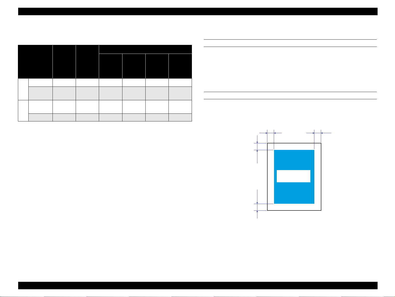
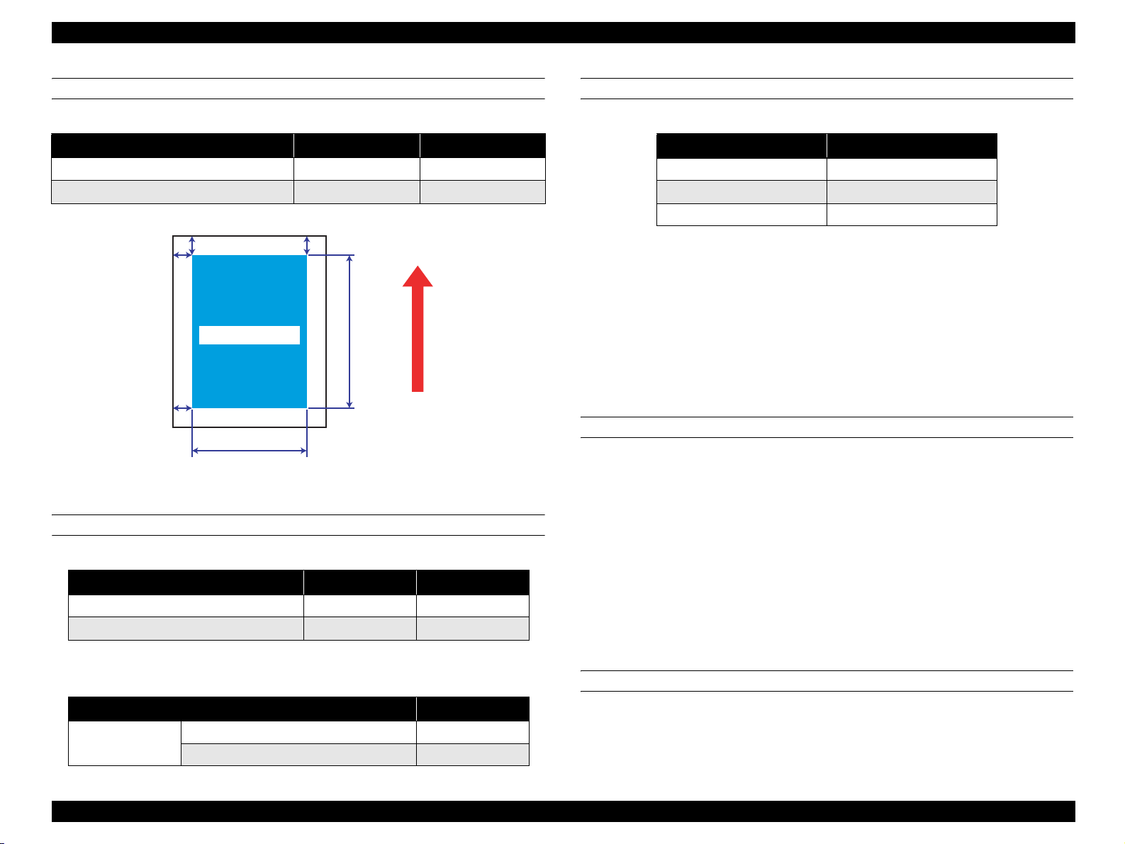
1.3.4 Printing Area
MAXIMUM PRINTABLE AREA
208 mm (width) x 289 mm (length)
NOTE: Although papers smaller than the maxi mum pr int abl e s ize ca n be printed
without margins, continuous printing on such papers, especially if the
left, right, top, and bottom margins beyond the paper exceed 4 mm,
causes contamination inside the printer and paper jam.
GUARANTEED PRINTING AREA
The guaranteed printing area is sho wn b elow. Th e min imum left, rig ht, to p an d bottom
margins are 4 mm for any type of paper.
4 mm4 mm
4 mm4 mm
Guaranteed
Printing Area
01000501
Figure 1-3. Guaranteed Printing Area
Product Description Paper Specifications 23
Page 24
EPSON AcuLaser C2600/2600 Revision A
1.4 Reliability and Serviceability
1.4.1 Reliability
MPBF/MTBF
60, 000 pages or more*
NOTE *1:
Assuming the ratio of color and monochrome is 1:1
*2:
Assuming an average power-on time is 300 hours per month.
1
/ 3,000 hours or more*
2
PAPER FEED RELIABILITY
Jam r a te
Table 1-19. Jam Rate
Paper Type
Reliability issue
Standard paper
Plain paper
Special paper
Simplex printing Duplex printing Simplex printing Duplex printing
1/4000 sheets or
less
1/2000 sheets or
less
1/100 sheets or
less
Environment A*
Paper feed error / multiple sheet feeding*
Table 1-20. Paper Feed Error/Multiple Sheet Feeding/
Paper Wrinkles/Creased Corner Rate
Reliability issue
Simplex printing Duplex printing Simplex printing Duplex printing
Standard paper
Plain paper
Special paper 1/25 sheets or less – 3/25 sheets or less –
1/1000 sheets or
less
1/500 sheets or
less
Environment A*
1
2/4000 sheets or
less
2/2000 sheets or
less
–
3
/ paper wrinkles / creased corner rate*
Paper Type
1
2/1000 sheets or
less
2/500 sheets or
less
Environment B*
3/4000 sheets or
less
3/2000 sheets or
less
3/100 sheets or
less
Environment B*
3/1000 sheets or
less
3/500 sheets or
less
6/4000 sheets or
less
6/2000 sheets or
less
6/1000 sheets or
less
6/500 sheets or
less
2
–
4
2
Note *1: Conditions for environment A (15 to 28 °C / 35 to 70 % RH)
Paper size: Standard-size
Humidity control: no regulation
*2: Conditions for environment B (10 to 30 °C / 15 to 65, 85 % RH)
Paper size: Standard-size
Humidity control: uncontrolled packed papers
*3 : The multiple sheet feeding rate does not include the performance at the boundary of
the originally loaded papers and additionally replenished papers.
*4: Counts creases more than C1 mm.
Product Description Reliability and Serviceability 24
Page 25
EPSON AcuLaser C2600/2600 Revision A
PRINTING START POSITION ACCURACY
Table 1-21. Printing Start Position Accuracy
A4/A3 Simplex printing Duplex printing
Main scanning direction Reference point (c)
Sub-scanning direction Reference point (a) ± 2.5 mm ± 2.5 mm
a
c
Printable Area
± 2.0 mm ± 3.0 mm
b
f
Feed Direction
d
e
01000601
Figure 1-4. Printing Start Position Accuracy
HEIGHT OF CURL ON OUTPUT PAPER
Table 1-24. Height of Curl on Output Paper
Paper type Height of Curl
Standard paper, P lain paper 30 mm or less
Transparency 15 mm or less
Other special papers No regulation
Note 1: The same for simplex and duplex printing
2: Measurement conditions:
Image occupation rate 5 % misaligned monochrome printing, or color
printing with 5 % of each color (total 20 %).
Print 10 sheets of 1p/J intermittent printing, then measure after an
interval of 1 minute.
Differs in accordance with the image occupation rate/array pattern
printing conditions.
1.4.2 Durability
PRINT VOLUME
Average: 8,000 pages/month*
Maximum: 48,000 pages/month (Color mode)*
120,000 pages/month (Monochrome mode)*
1
2
3
SKEW
Table 1-22. Skew
A4 Simp le x pr intin g Duplex printi ng
Main scanning direction (| a-b |) 1.47 mm 2.21 mm
Sub-scanning direction (| c-d |) 2.05 mm 3.07 mm
NOTE *1:
*2:
*3:
Product lifetime 480,000 pa ges as sumin g the ratio of color and mo nochro me
printing i s 1:1; 5 years assuming the usage is 8,000 page/months.
The ratio of color and monochrome printing is 1:1
Color printing only:30,000 pages/month
6,000 pages (MaxPV/day) x 20 day s
1.4.3 Serviceability
Table 1-23. Length Standard of Measurement
A4
Simplex printing
Duplex printing
Main scanning direction (e) 208 mm
Sub-scanning direct ion (f) 289 mm
Product Description Reliability and Serviceability 25
MTTR
Average 30 minutes or less
The MTTR value indicated above represents the time for service personnel to
locate and correct the malfunction only, and the time for ex amining malfunction is
not included.
Page 26
EPSON AcuLaser C2600/2600 Revision A
1.5 Service Conditions
AMBIENT TEMPERATURE AND HUMIDITY
Table 1-25. Ambient Temperature and Humidity
Temperature (ºC) Humidity (%RH) Other
Operating 1 0 to 35 15 to 85
Non-operating 0 to 35 10 to 85
AIR PRESSURE (ALTITUDE)
76 kPa or more (2,500 m or less)
LEVELNESS
Difference between front and back or left and right should be 1 º or less
No condensation allowed
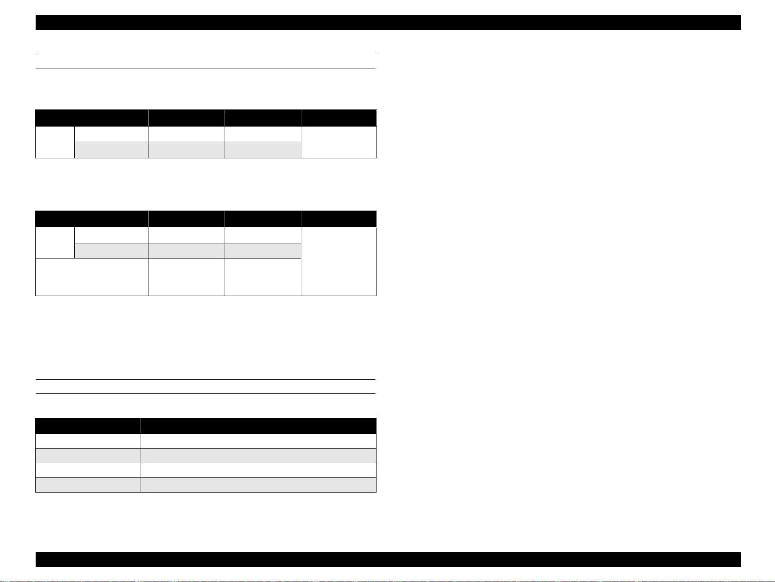
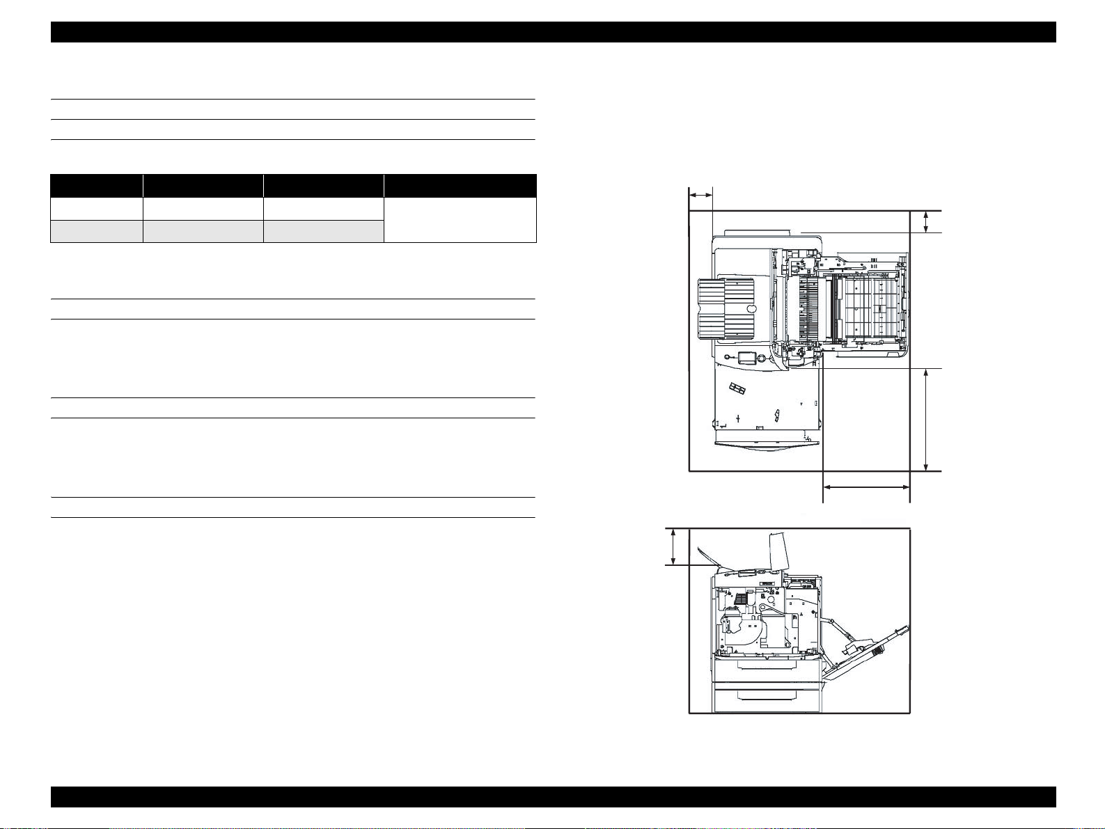
1.5.1 Space Requirements
In order to ensure that the printer operates properly, provide at least as much space as
shown in the diagram below.
100
100
430
ILLUMINATION
330
3,000 lx or less (do not expose to direct sunlight)
130
Unit: mm
01000701
Figure 1-5. Space Requirements
Product Description Service Conditions 26
Page 27

EPSON AcuLaser C2600/2600 Revision A
1.6 Conditions for Storage and Transport
AMBIENT TEMPERATURE AND HUMIDITY CONDITIONS
Table 1-26. Ambient Temperature and Humidity Conditions
Condition Tem perature (°C)
Normal conditions 0 to 35 15 to 80
Harsh condition s
High 35 to 40 High 80 to 95
Low -20 to 0 Low 5 to 15
Humidity (%RH)
(No condensation allowed)
RESISTANCE TO AIR PRESSURE (ALTITUDE)
0 to 2,500 m
(However, this is not applicable when pressurized to 70.9275 kPa or more during air
transportation.)
DROPPING
Guarantee
period
12 months after
manufacture
Maximum of
one month
VIBRATION
No damage under the following conditions
Conforms to divisional Assessment Standard of Transport (T-AE-05-001).
Frequency 5 to 55 Hz
1.5 G
Acceleration
Direction of application XYZ 3 directions
Frequency sweep Logarithmic sweep 10 minutes one way.
Number of cycles 3 cycles for each direction (1 hour each)
(However, constant 7.5 mm double amplitude is assumed between 5
and 10 Hz.)
COMPRESSION
Conforms to divisional Assessment Standard of Transport (T-AE-05-001).
No damage with 1 corner, 3 edges, and 6 sides dropping when packed.
Conforms to divisional Assessment Standard of Transport (T-AE-05-001).
Table 1-27. Dropping
Dropping height
Standard Main unit 42 cm 45.4 kg
Option
Duplex unit 82 cm 1.7 kg
500-sheet cassette unit 82 cm 6.8 kg
Package weight
(referential)
Product Description Conditions for Storage and Transport 27
Page 28
EPSON AcuLaser C2600/2600 Revision A
1.7 Electrical Characteristics
NOTE: The following sections do not include any optional units.
ELECTRICAL FAST TRANSIENT /BURSTS (AC LINE NOISE)
Ensure the following conditions using evaluation methods compliant with IEC610004-4.
1 kV: No errors excluding insignificant dot errors
2 kV: No damage to parts
INSTANTANEOUS OUTAGES
No effect on printing quality.
DIP: 1 cycle 100 % (at -10 % of rated current)
RESISTANCE TO STATIC ELECTRI CITY
Ensure the following conditions using evaluation methods compliant with IEC610004-2 and CISPR 24.
INSULATION RESISTANCE
10 MΩ or more
WITHSTAND VOLTAGE
No dielectric break down during application of the voltages shown below for a one
minute period.
Table 1-28. Withstand Voltage
Model Type
120 V AC 1250 V AC 1000 V
230 V AC 1500 V AC 3000 V
LEAK CURRENT
Between prima ry and s econd ary
supply transformers
Between power supply line and
chassis
120 V: 0.25 mA or less
230 V: 3.5 mA or less
Contact electric discharge 4.5 kV: No error on any device after applying
Aerial electric discharge 8.5 kV: No error on any device after applying
INRUSH CURRENT
100 A and 1/2 cycles or less for a cold start in an atmosphere at 23 ºC or more.
Product Description Electrical Characteristics 28
Page 29
EPSON AcuLaser C2600/2600 Revision A
1.8 Compatible Specification
SAFETY STANDARD
Table 1-29. Safety Standards
Model Type Applicable Sta nda r ds
120 V
230 V IEC60 95 0 3rd Edition
SAFETY STANDARD (LASER TRANSMISSION)
Table 1-30. Safety Standards (Laser Transmission)
Model Type Applicable Sta nda r ds
120 V FDA21CFR Chapter 1, Subchapter J, Section 1010, 1040
200 V series Compliant with IEC60825-1
Note : Refer to the Laser Specification
Wave length: 770-800 nm
Maximum output r a ting: 15 mW
UL60950 3rd Edition
CSA C22.2 No.60950
ELECTRICAL POWER HIGH FREQUENCY
230V: EN61000-3-3 (Flicker)
POWER CONSUMPTI O N
Conforms to International Energy Star Program standards
MISCELLANEOUS
Toner: Have no affect on the human body (conforms to OSHA,
TSCA, EINECS)
OPC: Have no affect on the human body (conforms to OSHA)
Ozone generation: Conforms to UL478 5th edition
Materials: Does not contain any materials prohibited in each country,
nor harmful substances above the permitted values
EMI STANDARDS
Table 1-31. EMI Standards
Model Type Applicable Sta nda r ds
120 V FCC Part 15 Subpart B, Class B
230 V
EN55022 (CIRSPR Publication 22), Class B
EN61000-3-2 (Harmonics) Class A
Product Description Compatible Specification 29
Page 30
EPSON AcuLaser C2600/2600 Revision A
1.9 Consumables/Periodic Replacement Unit
C A U T I O N
The print page-based service life values of the Consumables and
Periodical Replacement Parts are guidelines. The number of
printable pages changes depending on how they are printed. The
number of printable pages decreases depending on the intermittent
printing (where a few pages, one to several pages, are printed each
time), paper size, paper orientation, thick paper print ing, printed
document, frequent power-on/off, etc. Hence, the number of
printable pages of the consumables and periodical replacement
parts may become less than a half depending on the operating
conditions and environment of the user.
1.9.1 Specifications
Consumables (replaced by the user)
Table 1-32. Consumables
1
1
1
External
dimensions
(mm)
336 (W)
82 (D)
67 (H)
378 (W)
111 (D)
159 (H)
256 (W)
50 (D)
225 (H)
327 (W)
37 (D)
46 (H)
113 (D)
140 (H)
Weight
(kg)
0.9
0.8
0.9
1.3
0.2
0.1
2.3
Name Configuration
Toner cartridge (K)
(developer car tridge)
Toner cartridge (C)
Toner cartridge (M)
Toner cartridge (Y)
(developer car tridge)
Photoconductor unit
(a Waste toner collect or and a filter
unit are included in the package)
Waste toner collector*
(A filter is included in the package)
2
Filter*
Fuser unit (120V) Fuser 80,000 394 (W)
Fuser unit (230V) Fuser 80,000 2.3
Note *1: Approximate number of printed pages using A4 continuous printing at 5 % image
occupation rate.
The cartridge lifetime varies accordi ng to the paper size and type of printing (toner
save mode etc.).
*2: Rep laced at the same time as photoconductor unit o r the Waste toner collec tor.
2
Development,
Toner hopper
Waste toner
collection space
integrated drum
cartridge
Waste toner tank
Toner filter
Ozone filter
Lifetime
(pages)
5,000*
2,000*
5,000*
Monochrome:
40,000
Color: 10,000
Monochrome:
60,000
Color: 15,000
15, 000
Note : For details on the part life, see
“1.15 Life Details” (p.36).
Product Description Consumables/Periodic Replacement Unit 30
Page 31

EPSON AcuLaser C2600/2600 Revision A
Periodic replacement units (replaced by service personnel)
Table 1-33. Periodic Replacement Units
Name Lifetime (pages)
Transfer unit
Cleaning tape
Cleaner cl utc h 150,000
2nd transfer clutch 150,000
Paper eject roll e r 300,000
Post-fixing roller 300,000
Pickup roller 200,000
Monochrome: 100,000
Color: 60,000
1.9.2 Conditions for Storage and Transport
Ambient temperature and humidity cond itions
Table 1-34. Ambient Temperature and Humidity Conditions
Condition Temperature (°C)
Normal conditions 0 to 35 15 to 80
Harsh conditions
Note *: Storage time after opening is 12 months in the normal operating environment.
High 35 to 40 High 80 to 95
Low -20 to 0 Low 5 to 15
Humidity (%RH)
(No condensation allowed)
Resistance to Air Pressure (altitude)
Guarantee
period
18 months
(unopened*)
Maximum of
one month
740 to 1013 hPa (2,500 m or less)
(However, this is not applicable when pressurized to 70.9275 kPa or more during
air transportation.).
Package dropping
Direction of drop: 1 corn er, 6 sides, 3 edges
Dropping height: No damage with the conditions below
Table 1-35. Package Dropping
Package name Configuration
Toner cartridge (Y, M, C) 2,000 Toner cartridge 82 c m 1.2 kg
Toner cartridge (K, Y, M, C) 5,000 Toner cartridge 82 cm 1.3 kg
Photoconductor unit,
Photoconductor unit
Waste toner collector
Fuser unit Fuser unit 82 cm 3.2 kg
Waste toner collector,
Filter unit
Waste toner collector,
Filter unit
Dropping
height
82 cm 1.98 kg
82 cm 0.43 kg
Reference
(package
weight)
Product Description Consumables/Periodic Replacement Unit 31
Page 32

EPSON AcuLaser C2600/2600 Revision A
1.10 Maintenance
Table 1-36. Maintenance
Maintena nce item Period Maintenance method
• Paper f e ed roller
• Paper f e ed pad
• Retard roller
• Photoconductor wire cleaning
• Exposure window cleaning
• Patch sensor cleaning
When paper feed
problem occurs
When a warning is
issued (Clean Parts a)
When a warning is
issued (Clean Parts b)
When an error is
issued (Clean Sensor)
Wipe with a wet or dry cloth.
Clean by pulling out the cleaning knob
on the photocon ductor cartridge.
Clean by repeatedly pulling out the
cleaning knob.
Clean by opening and closing co ver D.
Product Description Maintenance 32
Page 33

EPSON AcuLaser C2600/2600 Revision A
1.11 External Appearance and Unit Names
1.11.1 Unit Names
Table 1-37. List of Unit Names
No. Name No. Name No. Name
1 Operation panel 7 Lock release lever (Cover A) 13 Rear cover
2 Cover B 8 MP tray 14 AC inlet
3 Output tray 9 Lock release lever (MP tray) 15 Duplex unit (Option)
4 Cover D 10 Handle (right) 16 Optional paper cassette unit
5 Lower paper cassette 11 Handle (left) 17 Cover E
6 Cover A 12 Power switch
<Top View>
2
3
1
<Front View> <Right Side View>
6
4
5
7 9
10
8
01000801
<Left Side View> <Rear View>
11
12
<Right Side View> Options installed
13
14
15
1617
01000901
Figure 1-6. External Appearance 1 Figure 1-7. External Appearance 2
Product Description External Appearance and Unit Names 33
Page 34

EPSON AcuLaser C2600/2600 Revision A
1.12 Engine Restrictions
1.12.1 Factors Limiting Printing Speed
Fuser cool down control
When the temperature of the Fusing roller edge reaches 235 °C, printing operation
stops for about 40 seconds until the temperature falls to 225 °C. If the temperature of
the Fusing roller edge reaches 194 °C when printing on smaller width papers, printing
operation stops for about 55 seconds until the temperature falls down enough.
(Monochrome printing speed becomes slow.)
Toner supply operations within a cartridge during a continuous Monochrome
printing.
When performing monochrome printing continuously, the rotary starts rotating in
process of print job in order to supply toner. (The speed of simplex monochrome
printing turns down.)
1. When the number of continuously printed pages reaches 255 (counted with
Vsync), the print process is interrupted while the rotary rotates 360° (until the
Vsync counts another 1) to supply toner.
2. When the integrated value of the toner counter reaches a certain level, the
print process is interrupted while the rotary rotates 360° (until the Vsync
counts another 1) to supply toner.
When performing duplex printing, the printing speed does not turn down as the rotary
rotates while the duplex unit is re-feeding the paper.
Patch Control (AIDC)
Patch control is activated by the engine factors on occasions described below.
At power on
When the Photoconductor unit is replaced
When the Toner cartridge is replaced
When the target value is changed due to the lifetime of the toner cartridge. (It
may affect printing speed.)*
Note *: Approximate frequency is as follows. (5 % duty or color printing with 5
% of each color, in case printing 5,000 pages continuously.)
•
In color mode of color model: Max. 16 times
•
In B/W mode (4xB/W mode) of color model: 4 times
•
B/W mode: 4 times
•
4xB/W mode: 1-2 times (4 times in
20,000 pages)
Printing stop time is as follows.
Color mode: 60 seconds
B/W mode: 22 seconds
4xB/W mode: 52 seconds
Toner supply control
After 3 hours have passed since the power-on without any printing operations,
developer rollers are rotated to stir toner inside of them in order to prevent banding on
printout from occurring. (This may cause delay in printing.)
1.12.2 Toner Duty Limiting Value
150 % (to prevent Fuser unit from twisting paper jam)
NOTE: Even if it exceeds 150 %, the engine (mechanical controller) does not
force a hard stop.
Product Description Engine Restrictions 34
Page 35

EPSON AcuLaser C2600/2600 Revision A
1.13 Notes When Replacing Consumables and Installing Optional Products
1.13.1 Consumables
Toner cartridge
When replacing the toner cartridges on occasion other than the toner end
occurs, move the toner cartridge to the replacement position using the control
panel.
Photoconductor unit
Can be replaced while the power supply to the main unit is either on or off.
Avoid replacing with a second hand u nit before the pro duct lifetime oth erwise
the lifetime will not be counted correctly.
Fuser unit
Can be replaced while the power supply to the main unit is either on or off.
Avoid replacing with a second hand u nit before the pro duct lifetime oth erwise
the lifetime will not be counted correctly.
1.13.2 Options
Duplex Unit
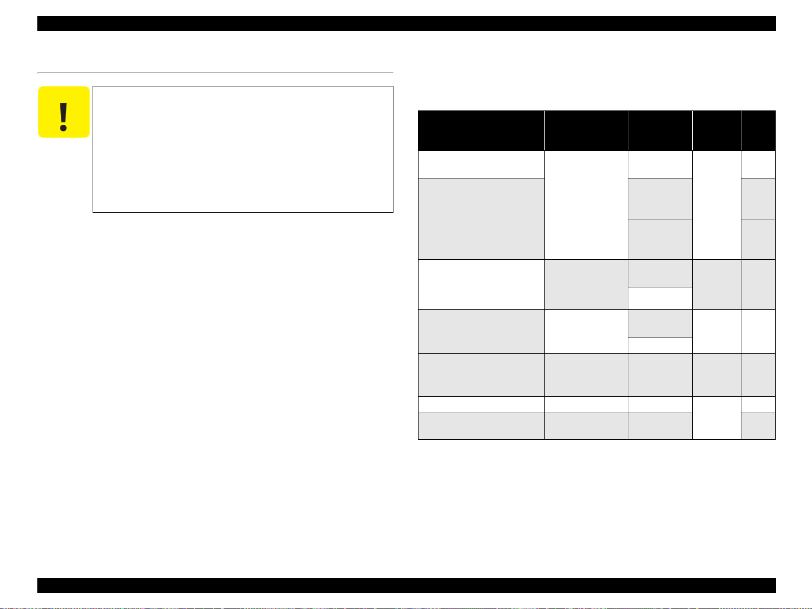
1.14 Notes on Fuser Pressure
Fuser unit is equipped with a pressure setting lever to switch between 2 levels of
pressures.
When the lever is not correctly set, toner offset, fix level reduction, paper wrinkle, or
OHP haze defects may be caused.
The relation between the fuser pressure and speed mode is as follows.
Table 1-38. The Relation between the Fuser Pressure and Speed Mode
Fuser pressure
Low pressure – – Envelopes
Standard
Std. mode Low speed mode 1 Low speed mode 2
Standard paper,
plain paper
Printing speed mode
Thick paper,
labels
Transparency
Turn off the main unit before installing.
When installed with the main unit power supply turned on, the unit will not be
detected.
Optional paper casse tte unit
Turn off the main unit before installing.
When installed with the main unit power supply turned on, the unit will not be
detected.
Option parts to expand the controller function
Turn off the main unit before installing, or the parts may be broken.
Product Description Notes When Replacing Consumables and Installing Optional Products 35
Page 36

EPSON AcuLaser C2600/2600 Revision A
1.15 Life Details
Regarding the lifetime of consumables and periodic replacement units:
Lifetime management methods
When the followings are fulfilled, it is required to replace the consumables or the
periodic replacement unit. (For more information, refer to “2.5.5 Control of
Consumables and Components Needing Periodic Replacement” (p.134).)
Table 1-39. Lifetime Management Methods
Unit Conditions
Toner cartridge
Photoconductor
unit
Fuser unit
Transfer belt unit
• Dot count value
• Development operation time
• Cumulative counted number of the Vsync.
• Cumulative number of pages counted per color.
• Waste toner full detection
• Cumulative time of rotation of the Gate roller (duration gate clutch is
ON)
• Cumulative time of rotation of the Main Drive Motor while the
temperature of the thermistor l ocated at the edge of the heat roller rises
above given level.
• Cumulative time of rotation of the Main Drive Motor.
• Cumulative time of rotation of the Main Drive Motor while the
temperature of the thermistor located at the center of the heat roller rises
above given level in Plain paper 2 mode.
• Cumulative number of cool -down cycles performed after print i ng on
narrow papers.
• Time period that the temperature of the center of the pressure roller is
kept above a prescribed level.
• Cumulative counted number of the Vsync.
• Number of paper feed for 2nd transfer
Product Description Life Details 36
Page 37

EPSON AcuLaser C2600/2600 Revision A
Life Details
Color Model
Table 1-40. Monochrome Mode (CMYK installed)
Print Volume: 1kp/M Print Volume: 8kp/M
Unit
Photoconductor unit*
Fuser uni t *
Transfer belt unit*
Cleaner clutch 150,000 cycle
2nd transfer clutch 150,0 00 cycle
2
Note *1: Print volume: 1 kp/M, 8kp/M
Average print r at i o is 5 %.
Power ON: Once a day
This indicates the value when the waste toner collector full is not detected in advance.
(If the average print ratio of all colors is 5 %, the collector still has room for waste toner when the part life is detected by the cumulative pages.)
*2: Print volume: 1 kp/M, 8kp/M
Power ON: Once a day
*3: 50 kp/j, ma k es a pa use fo r mor e tha n 1 minute.
*4: Shorten its l ife when the fusing roller has been used with its edges at high temp. for a long time due to the co ntinuous printing.
*5: Print volume: 1 kp/M, 8kp/M
Average print r at i o is 5 %.
Power ON: Once a day
Specification (page)
1
5
40,000
80,000
100,000
Printing speed Continuous printing (page) 1p/J (page) 2p/J (page) 4p/J (page) Continuous printing (page) 1p/J (page) 2p/J (page) 4p/J (pag e)
Std. mode (plain paper 1)
Std. mode (plain paper 2)
Low speed mode 1
Low speed mode 2
Std. mode (plain paper 1) 80,000*
Std. mode (plain paper 2) 78,000 37,000 51,000 62,000 50,000 49,000 80,000 60,000
Low speed mode 1
Low speed mode 2
Std. mode (plain paper 1)
Std. mode (plain paper 2)
Low speed mode 1
Low speed mode 2
Std. mode (plain paper 1)
Std. mode (plain paper 2)
Low speed mode 1
Low speed mode 2
Std. mode (plain paper 1)
Std. mode (plain paper 2)
Low speed mode 1
Low speed mode 2
31,100 11,700 17,300 22,700 40,000 13,300 21,000 29,500
9,500 7,100 8,200 8,900 10,600 7,700 9,000 9,800
3
4
/50,000*
40,000 40,000 40,000 40,000 40,000 40,000 40,000 40,000
100,000 63,900 93,900 100,000 100,000 72,600 100,000 100,000
52,600 39,000 44,800 48,400 58,400 42,000 48,900 53,300
1,673,900 140,200 263,200 468,800 5,289,500 148,700 294,800 579,700
140,200 72,500 95,500 140,200 148,700 74,700 99,400 149,200
1,681,300 73,200 142,800 272,700 3,299,200 74,800 149,000 296,300
140,300 49,200 73,200 115,700 146,300 49,900 74,800 119,400
51,000 62,000 70,000 80,000*3/50,000*
4
80,000 80,000 80,000
Product Description Life Details 37
Page 38

EPSON AcuLaser C2600/2600 Revision A
Table 1-41. Color Mode
Print Volume: 1kp/M Print Volume: 8kp/M
Unit
Photoconductor unit*
Fuser uni t *
Transfer belt unit *
Cleaner clutch 150,000 cycle
2nd transfer clutch 150,0 00 cycle
2
Note *1: Print volume: 1 kp/M, 8kp/M
Average print r at i o is 5 %.
Power ON: Once a day
This indicates the value when the waste toner collector full is not detected in advance.
(If the average print ratio of all colors is 5 %, the collector still has room for waste toner when the part life is detected by the cumulative pages.)
*2: Print volume: 1 kp/M, 8kp/M
Power ON: Once a day
*3: 50 kp/j, ma k es a pa use fo r mor e tha n 1 minute.
*4: Shorten its l ife when the fusing roller has been used with its edges at high temp. for a long time due to the co ntinuous printing.
*5: Print volume: 1 kp/M, 8kp/M
Average print r at i o is 5 %.
Power ON: Once a day
Specification (page)
1
5
10,000
80,000
60,000
Printing speed Continuous printing (page) 1p/J (page) 2p/J (page) 4p/J (page) Continuous printing (page) 1p/J (page) 2p/J (page) 4p/J (pag e)
Std. mode (plain paper 1)
Std. mode (plain paper 2)
Low speed mode 1
Low speed mode 2
Std. mode (plain paper 1) 60,000 42,000 49,000 54,000 80,000 72,000 80,000 80,000
Std. mode (plain paper 2) 60,000 32,000 42,000 49,000 80,000 38,000 60,000 60,000
Low speed mode 1
Low speed mode 2
Std. mode (plain paper 1)
Std. mode (plain paper 2)
Low speed mode 1
Low speed mode 2
Std. mode (plain paper 1)
Std. mode (plain paper 2)
Low speed mode 1
Low speed mode 2
Std. mode (plain paper 1)
Std. mode (plain paper 2)
Low speed mode 1
Low speed mode 2
10,000 7,000 8,700 9,900 10,000 7,600 9,600 10,000
6,200 5,100 5,600 5,900 6,700 5,300 5,900 6,300
40,000 40,000 40,000 40,000 40,000 40,000 40,000 40,000
60,500 38,200 47,300 53,600 68,200 41,200 51,800 59,500
33,900 27,600 30,500 32,100 36,200 29,200 32,300 34,100
137,600 72,500 95,500 140,200 145,800 74,700 99,400 148,700
137,600 72,500 95,500 140,200 145,800 74,700 99,400 148,700
138,900 73,200 96,800 142,800 146,000 74,800 99,600 149,000
138,900 73,200 96,800 142,800 146,000 74,800 99,600 149,000
Product Description Life Details 38
Page 39

EPSON AcuLaser C2600/2600 Revision A
Monochrome Model
Table 1-42. Monochrome Mode
Print Volume: 1kp/M Print Volume: 8kp/M
Unit
Photoconductor unit*
Fuser uni t *
Transfer belt unit *
Cleaner clutch 150,000 cycle
2nd transfer clutch 150,0 00 cycle
2
Note *1: Print volume: 1 kp/M, 8kp/M
Average print r at i o is 5 %.
Power ON: Once a day
This indicates the value when the waste toner collector full is not detected in advance.
(If the average print ratio of all colors is 5 %, the collector still has room for waste toner when the part life is detected by the cumulative pages.)
*2: Print volume: 1 kp/M, 8kp/M
Power ON: Once a day
*3: 50 kp/j, ma k es a pa use fo r mor e tha n 1 minute.
*4: Shorten its l ife when the fusing roller has been used with its edges at high temp. for a long time due to the co ntinuous printing.
*5: Print volume: 1 kp/M, 8kp/M
Average print r at i o is 5 %.
Power ON: Once a day
Specification (page)
1
5
40,000
80,000
100,000
Printing speed Continuous printing (page) 1p/J (page) 2p/J (page) 4p/J (page) Continuous printing (page) 1p/J (page) 2p/J (page) 4p/J (pag e)
Std. mode (plain paper 1)
Std. mode (plain paper 2)
Low speed mode 1
Low speed mode 2
Std. mode (plain paper 1) 80,000*
Std. mode (plain paper 2) 78,000 37,000 51,000 62,000 50,000 49,000 80,000 60,000
Low speed mode 1
Low speed mode 2
Std. mode (plain paper 1)
Std. mode (plain paper 2)
Low speed mode 1
Low speed mode 2
Std. mode (plain paper 1)
Std. mode (plain paper 2)
Low speed mode 1
Low speed mode 2
Std. mode (plain paper 1)
Std. mode (plain paper 2)
Low speed mode 1
Low speed mode 2
40,000 12,800 19,800 27,200 40,000 13,600 21,600 30,600
10,200 7,500 8,700 9,500 10,700 7,800 9,100 99,00
3
4
/50,000*
40,000 40,000 40,000 40,000 40,000 40,000 40,000 40,000
100,000 63,900 93,900 100,000 100,000 72,600 100,000 100,000
52,600 39,000 44,800 48,400 58,400 42,000 48,900 53,300
1,673,900 140,200 263,200 468,800 5,289,500 148,700 294,800 579,700
140,200 72,500 95,500 140,200 148,700 74,700 99,400 149,200
1,681,300 73,200 142,800 272,700 3,299,200 74,800 149,000 296,300
140,300 49,200 73,200 115,700 146,300 49,900 74,800 119,400
51,000 62,000 70,000 80,000*3/50,000*
4
80,000 80,000 80,000
Product Description Life Details 39
Page 40

EPSON AcuLaser C2600/2600 Revision A
1.16 Controller Specifications
1.16.1 Controller Basic Specifications
CPU: VR5532A (350 MHz)
Enhanced technology: nPGI, CRIT, RIT (CLC)
RAM: SDRAM
Standard: 64 MB (64 MB SDRAM DIMM in the expansion
RAM slot (S0))
Expansion RAM slot: 2-slot expansion RAM slot (1 slot is already used by
standard RAM) Maximum 512 MB
Expansion RAM: 16 MB, 32 MB, 64 MB, 128 MB, and 256 MB RAM
DIMM for Epson (from Buffalo)
Program ROM: 16 MB Flash ROM
Expansion ROM : 1 slot. Ca n be used for installing enhanced fonts or
PCL5C option.
Panel: LCD 22 digits, 5 line; 3 LEDs; 6 buttons
Interface
Standard
• USB interface: 1 ch (Rev. 2.0 HS (with D4 support))
• Network interface: 1 ch (10Base-T/100Base-TX)
• Parallel interface: 1 ch (IEEE1284 compliant bi-directional B-type
connector, Compatibility, Nibble, ECP)
• Type-B interface: 1 slot
Printer setting: Panel setting, EJL command, and MIB.
Memory element - 128 Kbits serial type EEPROM
Printer mode
Standard: ESC/Page Color, Adobe PostScript 3 (17 fonts), PCL6,
PCL5e, ESC/P2, FX, I239X
Option: PCL5C
Possible to operate in color mode of AcuLaser C2600 or of
AcuLaser 2600 that upgraded to color model
Other: EJL mode
DCC mode
RCC mode
Auxiliary software: Status Sheet, Toner Check Sheet
Maintenance Mode (Engine Status Sheet, Print Log Report)
Update function for mechanical controller firmware
EpsonNet Config (Web)
Installation method: Fixed to the main body
1.16.2 Controller Configuration
Two types of controllers are defined in the EEPROM to enable switching between
color (AcuLaser C2600) and monochrome (AcuLaser 2600) models. Switching
between AcuLaser C2600 and AcuLaser 2600 is done by using the model information
in the EEPROM.
Soft jumper 1
1 AcuLaser C2600
2 AcuLaser 2600
Soft jumper 2-16
Undefined
NOTE: This definition is set by the EJL command, not by the control panel
and MIB. This setting is changed if the main board is replaced while
at work. (Refer to “5.1.3 Adjustment Execution Timing” (p.366).)
Product Description Controller Specifications 40
Page 41

EPSON AcuLaser C2600/2600 Revision A
1.16.3 External Interface Specifications
The printer provides the following host interfaces.
USB interface (Rev. 2.0 HS, Supports bi-directional (D4))
Network interface (10Base-T/100Base-TX)
Parallel interface (IEEE1284)
Type-B interface
The locations of the respective interfaces are shown below.
Network Interface
Type-B Interface
Parallel Interface
PARALLEL INTERFACE SPECIFICATIONS
Interface type: IEEE1284 bidirectional high-speed parallel interface
Operation mode: Compatibility, Nibble, ECP
Connector type name: 57RE-40360-830B (D7A) DDK or equivalent one
Compliant plug: Equivalent to AMPHENOLE
CMD: PJL, EJL, PCL, ESCPAGE-04, ESCPAGECOLOR-01, PCLXL, POSTSCRIPT, PCL5C*1, *
Note *1: Hidden when operating in monochrome mode.
*2 : Added when the PCL5C option DIMM is installed.
At the factory default settings, there are two types of MDL and DES which remain
unchanged even if the printer operating mode of the model is changed to color or to 1or 4-cartridge monochrome.
MDL for the color model is AcuLaser C2600 and for the monochrome model is
AcuLaser 2600.
DES for the color model is EPSON AcuLaser C2600 and for the monochrome model is
EPSON AcuLaser 2600.
USB INTERFACE SPECIFICATIONS
2
Universal Serial Bus Specification Rev.2.0 HS is supported.
USB model specific number: 33
USB Interface
When the printer is connected to the PC by the USB port, the interface does not support
01001001
Figure 1-8. Location of External Interfaces
D4. However D4 support is available if the EPSON external LAN option is connected.
The CMD of Device ID differs from the parallel interface with D4L3 being added.
Printer Name and Product Name are common to both AcuLaser C2600 and AcuLaser
2600.
CMD: PJL, EJL, PCL, ESCPAGE-04, ESCPAGECOLOR-01, PCLXL, POSTSCRIPT,
PCL5C*
Note *1: Hidden when operating in monochrome mode.
*2 : Added when the PCL5C option DIMM is installed.
1, *2
, D4L3
Product Description Controller Specifications 41
Page 42

EPSON AcuLaser C2600/2600 Revision A
NETWORK INTERFACE SPECIFICATIONS
This printer supports 10BaseT/100BaseTX Ethernet interfaces as standard.
Printing protocol
TCP/IP
LPR, FTP, IPP, PORT2501, PORT910 0
Microsoft N etwork
Net BIOS over TCP/IP, Net BIOS over NetBEUI
Netware
Operation mode: Standby (facto ry default s etting), NDS Print Ser ver, Bindery
Print Server, Remote Printer
AppleTalk
Management protocol
TCP/IP
SNMP, HTTP, TELNET, DHCP, BOOTP, APIPA, PING, DDNS, mDNS*,
SNTP, SSDP, ENPC
MS Network (NetBEUI)
SNMP, ENPC
NetWare
SNMP, ENPC
AppleTalk
SNMP, ENPC
Note *: mDNS is used with Rendezvous.
NOTE: Entity Typ e
Refer to “Option interface specifications” (p42).
OPTION INTERFACE SPECIFICATIONS
The printer is provided with one Type-B optional interface slot as standard.
Main System Type: MTP600dpi, PW5100dt600dpi, PRG(*****)rev,
AP800ma, SPD0fast, D4
Asterisks (*****) indicate ROM version.
Printer Name: The factory default setting is the same as Product
Name.
Product Name*
1
: Color model : AcuLaser C2600
monochrome model: AcuLaser 2600
Emulation Type/Entity Type
Table 1-43. Emulation Type/Entity Type
Emulation Emulation Type Entity Type
PS POSTSCRIPT-00 LaserWriter
ESC/Page Color ESCPAGECOLOR-01 EPSONPAGECOLOR1
ESC/Page ESCPAGE-04 –
LJ4 PCL5E-00 EPSONPCL5
I239X PRPXL24-01 EPSONPRPXL24
GL2 HPGL2-01 EPSONHPGL2
FX ESCP9 EPSONFX
ESCP2 ESCPL2 EPSONLQ2
PCLXL PCLXL EPSONPCLXL
PCL5C*
Note *1: The product name remains unchanged even if the printer operating mode is switched
*2: Only when the PCL5C option DIMM is installed.Hidden when operating in
2
between color and monochrome. (Remains at factory default settings.)
monochrome mode.
PCL5C-00 EPSONPCL5C
Product Description Controller Specifications 42
Page 43

EPSON AcuLaser C2600/2600 Revision A
1.17 Control Panel
1.17.1 External Appearance and Names
Table 1-44. Indicators
Indicators Function
LCD 4 lines x 20 characters (132 x 65 dots)
On: The printer is ready to print.
Ready LED
Data LED
Error LED
Note : Blinking 1:The LED blinks on and off at 0.3 second intervals.
Off: The printer cannot print.
If an error occurs, the printer cannot print and the Ready LED goes off.
On: Received data still remains in the printer unprinted.
Off: Valid print data does not exist in the printer.
Blinking: The printer is receiving or processing print data.
Blinking 1:The printer can recover from the error and continue the job when the
[Start/Stop] button is pressed.
If “Auto Cont” is set to ON, the error is cancell ed automa tically after a
certain interval without pressing the [Start/Stop] button.
On: An error that must be canceled by th e operator has occurred.
When the error is canceled the printer recovers aut omatically.
Blinking 2:An error where the operator must cancel the error and press the [Start/
Stop] button has occurred.
Setting “Auto Cont” to ON has no effect.
Blinking 2:The LED blinks on and off at 0.6 second intervals.
LCD (4 Lines x 20 Characters)
[Cancel Job] Button
Data LED (Yellow)
Ready LED (Green)
[ (2)] Button
[ (1)] Button
[ (4)] Button
[ (3)] Button
Figure 1-9. External View of Control Panel
Error LED (Red)
[Start/Stop] Button
01001102
Product Description Control Panel 43
Page 44

EPSON AcuLaser C2600/2600 Revision A
Summary of Button Functions
Table 1-45. Summary of Button Functions
Button
Name
Start
/Stop
Cancel Job
(1) Disabled Disabled
Sets printer to offline.
1. Short press:
Deletes printing data.
2. Long press
(2 seconds or longer):
Deletes all p r inting data.
Enters the Informat io n Menu in
(3)
the Panel Setting mode.
(2) Disabled Disabled Disabled
(4) Disabled Disabled Disabled
Ready Offline Error Warning Panel Setting Help
1. Short press:
Sets printe r to Ready.
2. Long press
(2 seconds or longer):
Forcibly ejects paper.
1. Short press:
Deletes printing data.
2. Long press
(2 seconds or longer):
Deletes all printing data.
Enters the Information Men u in
the Panel Setting mode.
1. Recoverable error:
Cancels the error.
2. Unrecoverable error:
Displays “Unable Clea r
Error”.
1. Short press:
Deletes printing data.
2. Long press
(2 seconds or longer):
Deletes all p r inting data.
Enters the Information Menu in
the Panel Setting mode.
1. When Help is available:
Enters Help.
2. When Help is not available:
Disabled
Switches betwe en Ready/Offline
while a warning is displayed
1. Short press:
Deletes printing data.
2. Long press
(2 seconds or longer):
Deletes all printing data.
Enters the Information Men u in
the Panel Setting mode.
1. When Help is availa ble:
Enters Help.
2. When Help is not avai lable:
Disabled
Switches the warning displaye d
when multiple warnings occur.
Switches the warning displaye d
when multiple warnings occur.
Leaves Panel Setting and returns to the
original mode
Leaves Panel Setting
1. Short press:
Deletes print data.
2. Long press
(2 seconds or longer):
Deletes all print data .
1. When a Menu is displayed:
Switches to displaying an Item.
2. When a non-executable Item is dis played:
Switches to displaying a Value.
3. When an executab le Ite m is displayed:
Executes printing or processing.
4. When a Value is displayed:
Sets the Valu e.
1. When a Menu is displayed:
Returns to the normal mode.
2. When an Item or Value is di spla yed:
Returns to the p revious level.
1. When a Menu is displayed:
Displays the previous/next Menu
2. When an Item is displaye d:
Displays the previous/next Item
3. When a Value is displayed:
Displays the previous/next Value
1. When a Menu is displayed:
Displays the previous/next Menu
2. When an Item is displaye d:
Displays the previous/next Item
3. When a Value is displayed:
Displays the previous/next Value
In the Help mode
Switches be tween
Ready/Offline
Leaves Help
1. Short press:
Deletes print data.
2. Long press
(2 seconds or longer):
Deletes all p r int data.
Disabled
Leaves the Help mode
and returns to the
original mode.
Displays the previous/
next Help screen.
Displays the previous/
next Help screen.
Product Description Control Panel 44
Page 45

EPSON AcuLaser C2600/2600 Revision A
1.17.2 Panel Settings List
The printer settings are listed below.
Underlined value in the Setting value column are factory default settings.
Information Menu
Setting Setting values
Status Sheet –
9
8*9
1
2
3
4
5
6
7
–
–
–
–
–
–
–
E******F to EF
E******F to EF
E******F to EF
E******F to EF
E******F to EF
E******F to EF
E******F to EF
Toner Check Sheet*
Reserve Job List*
Form Overlay List*
Network Status Sheet*
AUX Status Sheet*
USB Extl/FstatusSht*
PS3 Status Sheet –
PS3 Font List –
ESC/Page Font Sample*
LJ4 Font Sample –
ESCP2 Font Sample –
FX Font Sample –
I239X Font Sample –
C Toner*
8*9
M Toner*8*
Y Toner*
K Toner*8*
8*9
9
Toner Ave.*
Photocon*
Fuser Unit*
8
8
Setting Setting values
Total Pages*
Color Pages*
B/W Pages*8*
8
8*10
0 to 99999999
0 to 99999999
10
0 to 99999999
Note *1: Not displayed when operat ing in B/W mode.
*2: Displayed only when job is registered in Quick Print Job.
*3: Displayed only when there is Form Overlay. All the registered color forms and
monochrome forms are printed.
It will be printed that each form is a color or monochrome.
*4: Displayed only when “Network I/F = On”.
*5: Displayed only when Type-B interface with Level 3 support is installed and started up
with “AUX I/F = On”.
*6: Displayed only when a USB device with D4 support is connected and started up with
“USB I/F = On”.
*7: Not displayed on the panel .
*8: This item is for display only and cannot be changed.
*9: If the printer is operating in B/W mode, only K toner is displayed. When operating in
4xB/W mode, the dis play change as follows.
C Toner → KC Toner
M Toner → KM Toner
Y Toner → KY Toner
K Toner → KK Toner
Toner Ave.: Added when operating in 4xB/W mode.
*10:Availabe only in the color mode.
Product Description Control Panel 45
Page 46

EPSON AcuLaser C2600/2600 Revision A
Tray Menu
Setting Setting values
MP Tray Size A4
, A5, B5, LT, HLT, GLT, EXE, MON, C10, DL, C5, C6, IB5
LC1 Size A4, LT
LC2 Size*
1
A4, LT
MP Type Plain, Letterhead, Recycled, Color, Transprncy, Labels
LC1 Type Plain
LC2 Type*
1
, Letterhead, Recycled, Color
Plain, Letterhead, Recycled, Color
Note *1: Displayed only when the optional paper cassette unit is installed.
Emulation Menu
Setting Setting values
Parallel Auto
, LJ4, ESCP2, FX, I239X, PS3, GL2, P5C*
USB Auto, LJ4, ESCP2, FX, I239X, PS3, GL2, P5C*
Network Auto, LJ4, ESCP2, FX, I239X, PS3, GL2, P5C*
1
AUX*
Auto, LJ4, ESCP2, FX, I239X, PS3, GL2, P5C*
Note *1: Displayed only when the Type-B interface is installed.
*2 : Displayed only when the optional P5C module is installed.
2
2
2
2
Printing Menu
Setting Setting values
, A5, B5, LT, HLT, GLT, EXE, MON, C10, DL, C5, C6, IB5,
Page Size
Wide A4 Off, On
Orientation Port
Resolution 600, 300
RITech On
Toner Save Off, On
Image Optimum Auto
Top Offset -99.0 to 0.0 to 99.0 mm step 0.5 mm
Left Offset -99.0 to 0.0
Top Offset B -99.0 to 0.0 to 99.0 mm step 0.5 mm
Left Offset B -99.0 to 0.0
Note *1: CUSTOM (user defined) size (width x length) is as follows.
Length: 148 mm ~ 297 mm
Width: 98 mm ~ 216 mm
A4
CTM*
, Off
1
, Land
, Off, On
to 99.0 mm step 0.5 mm
to 99.0 mm step 0.5 mm
Product Description Control Panel 46
Page 47

EPSON AcuLaser C2600/2600 Revision A
Setup Menu
Setting Setting values
Lang
Lang
Sprache
Lingua
IDIOMA
SPRÅK
Sprog
Taal
Kieli
Líng.
Time Out 0, 5 to 60 to 300 step 1
Paper Source Auto
MP mode Normal, Last
ManualFeed Off
Copies 1 - 999
Quantity*
2
Duplex Off, On
Binding Long Edge
Start Page*
3
Paper Type Normal
Page Side Front, Back
Skip Blank Page*
4
Auto Eject Page Off, On
Size Ignore Off
Auto Cont Off, On
Page Protect Auto
English
Français
Deutsch
Italiano
ESPAÑOL
SVENSKA
Dansk
Nederlands
SUOMI
Português
, MP, LC1, LC2*
, 1st Page, EachPage
1 - 999
, Short Edge
Front, Back
, Thick, Trnsprnc
Off, On
, On
, On
Setting Setting values
Toner Out Stop, Continue
LCD Contrast 0 to 7
Panel Lock*
5
to 15
Off, On
Note *1: Displayed and selectable only when the optional paper cassette unit is installed.
*2: Not displayed on the pane l nor printed on the Status Sheet. Can be set with EJL and
PJL. It is not stored on EEPROM.
*3 : Displayed and selectable only when the duplex unit is installed. The following paper
sizes are available for duplex printing; A4, A5, Letter, EXE, and B5. Other sizes are
available for simplex printing.
*4: Valid in the PCL5e and ESC/Pa ge, ESC/P2, FX, and I239X modes.
*5: Not displayed on the pane l nor printed on the Status Sheet. Can b e s e t with EJL,
EPSON Net Config (Web), etc.
1
Product Description Control Panel 47
Page 48

EPSON AcuLaser C2600/2600 Revision A
Mode Config Menu
Setting Setting values
Remove All Toner *
Change Mode*2 B/W –
Change Mode*
Change Mode*2 Color –
KC Toner*
3
KM Toner*
KY Toner*
KK Toner*
3
3
Note *1: Removes all C, M, Y, and K toners. Used for example, at shipping.
This operation is executable only from the pa nel. Ope ration fro m EJL and MIB are no t
supported.
*2: Switches the printer operating mode (B/W mode, 4xB/W mode, or color mode).
This operation is executable only from the pa nel. Ope ration fro m EJL and MIB are no t
supported.
Current mode is not displayed.
B/W Starts the process for removing C, M, and Y toners. Reboot the printer
4xB/W Replaces the C, M, and Y toners with K toners. Reboot the printer after
Color Changes from the monochrome mode (B/W mode or 4xB/W mode) to
*3 : The toner cartridge specified with KC, KM, KY and KK is made disabling. It is
displayed only 4xB/W mode.
This operation is executable only from the pa nel. Ope ration fro m EJL and MIB are no t
supported.
1
2
4xB/W –
Enable, Disable
3
Enable, Disable
Enable, Disable
Enable, Disable
after removing the C, M and Y toners. After the reboot, the printer
becomes a B/W mode.
replacing the C, M and Y toners. After the reboot, the p rin t er becomes a
4xB/W mode.
the color mode. When changing from B/W mode, reboot the printer after
installing the C, M and Y toners. When changing from 4xB/W mode,
reboot the printer after replacing the K toners in the C, M, and Y toner
positions with the C, M, and Y toners. After the reboot, the printer
becomes a color printing mode.
–
Reset Menu
Setting Setting values
Clear Warning –
Clear All Warnings –
Reset –
Reset All –
SelecType Init –
Change Toner*
Change Toner*
Change Toner*
1
1
1
C (KC)*
M (KM)*
Y (KY)*
Change Toner K (KK)*
Note *1: Not displayed operating in B/W mode.
*2: Charac te r s in the brac k et are displayed in 4xB/W mo de .
Quick Print Job Menu*
1
Setting Setting values
User xxxxxxxxxxxxxxxx
2
Job*
Copies*
Delete*3*
3
4
xxxxxxxxxxxxxxxx
1 ~ 999
Note *1: Thi s menu is not displayed when none of Verify Job, Re- print Job, or Stored Job is
registered.
*2 : This item is displayed when at the User display, “Value” (User name) is selected and
the Enter switch is pressed.
*3 : This item is displayed, selectable, and executable when at the Job display, “Value”
(Job name) is selected and the Enter switch is pressed.
Exits the SelecType mode after execution.
*4: By executing “Delete” the menu changes to “Job”. User is displayed when no jobs are
registered.
Exits SelecType when there are no users.
2
2
2
2
–
Product Description Control Panel 48
Page 49

EPSON AcuLaser C2600/2600 Revision A
Confidential Job Menu*
1
Setting Setting values
User xxxxxxxxxxxxxxxx
Enter Password*
3
Job*
4
Copies*
4*5
Delete*
2
xxxx
xxxxxxxxxxxxxxxx
1 ~ 999
–
Note *1: This menu is not displayed when no Confidential Job is registered.
*2: This item is displayed when at the User display, “Value” (User name) is selected and
the Enter switch is pressed.
Passwords are ente red using the 1 [ ], 2 [ ], 3 [ ], and 4 [ ] buttons.
*3 : After the password is input at the Enter Password display, if the password entered is
correct, this item is displayed.
*4: This item is displayed, selectable , and executable when at the Job display, “Value”
(Job name) is selected and the Enter switched is pressed.
Exits the SelecType mode after execution.
*5: By executing “Delete”, the menu changes to “Job” User is displayed when no jobs are
registered.
Exits SelecType when there are no users.
Parallel Menu*
1
Setting Value
Parallel I/F On
, Off
Speed Fast, Normal
Bi-D Nibble, ECP
, Off
Buffer Size Normal, Maximum, Minimum
Note *1: After this item is changed, the setting value takes effect after a warm boot or after the
power is turned on again. While it is reflected in the Status Sheet and EJL read-back,
the actual change takes effect after a warm boot or after the power is turned on again.
USB Menu
Setting Value
USB I/F*
USB Speed*
USB ExtI/Fconfg*
Get IP Address*
IP Address*
Subnet Mask*
Gate Way*
Netware*
AppleTalk*
MS Network*
Rendezvous*
USB Ext I/F Init*
Buffer Size*
Note *1: After this item is changed, the setting value takes effect after a warm boot or after the
1
1
2
3
3*4*5
3
3
3
3
3
3
3
1
On, Off
HS, FS
No, Yes
Panel, Auto, PING
0.0.0.0 to 25 5.255.255.255
0.0.0.0 to 25 5.255.255.255
0.0.0.0 to 25 5.255.255.255
On, Off
On, Off
On, Off
On, Off
–
Normal, Maximum, Mi nimum
power is turned on again. While it is reflected in the Status Sheet and EJL read-back,
the actual change takes effect after a warm boot or after the power is turned on again.
*2: Displayed only when a USB external device with D4 support is connected.
Changed to “USB Config = No” automatically when exiting the pan el setting s.
*3: Displayed only when a USB external device with D4 support is connected, and “USB
Config = Yes”
Content of the display depends on the USB external device settings.
*4: Displayed only when “Get IPAddress = Auto”. Cannot be changed.
*5 : When Get IPAddress is changed from “Panel” or “PING” to “Auto”, the panel setting
values are saved.
Then when “Auto” is changed to “Panel” or “PING”, the saved setting valu es are
displayed.
192.168.192.168 if the settings are not made from the panel.
Product Description Control Panel 49
Page 50

EPSON AcuLaser C2600/2600 Revision A
Network Menu*
1
Setting Value
Network I/F On, Off
Network Config No, Yes
Get IP Address*
IP Address*2*
Subnet Mask*
Gate Way*
Netware*
AppleTalk*
MS Network*
Rendezvous*
Link Speed*
2
3
2
2
2
2
2
2
2
Panel, Auto, PING
0.0.0.0 to 255 .255.255.255
0.0.0.0 to 255 .255.255.255
0.0.0.0 to 255 .255.255.255
On, Off
On, Off
On, Off
On, Off
Auto, 100 Full, 100 Half, 10 Full, 10 Half
Buffer Size Normal, Maximum, Minimum
Note *1: After this item is changed, the setting value takes effect after a warm boot or after the
power is turned on again. While it is reflected in the Status Sheet and EJL read-back,
the actual change takes effect after a warm boot or after the power is turned on again.
*2: Displayed and selectable only when “Network Config = Yes”.
*3: The actual valid value is displayed (but cannot be changed) when “Get IPAddress =
Auto”.
When “Get IPAddress = Auto” is changed to “Panel” or “PING”, the former value set
for “Panel” or “PING” is displayed.
When “Get IPAddress = Auto”, IP Address is not shown on the Status Sheet.
AUX Menu*1*
2
Setting Value
AUX I/F On, Off
AUX Config*
Get IP Address*3*
IP Address*3*4*
Subnet Mask*3*
Gate Way*3*
Netware*3*
AppleTalk*3*
MS Network*3*
Rendezvous*3*4*
AUX Init*3*
3
4
5
4
4
4
4
4
6
4
No, Yes
Panel, Auto, PING
0.0.0.0 to 25 5.255.255.255
0.0.0.0 to 25 5.255.255.255
0.0.0.0 to 25 5.255.255.255
On, Off
On, Off
On, Off
On, Off
–
Buffer Size Normal, Maximum, Minimum
Note *1: After this item is changed, the setting value takes effect after a warm boot or after the
power is turned on again. While it is reflected in the Status Sheet and EJL read-back,
the actual change takes effect after a warm boot or after the power is turned on again.
*2: Displayed only when Type-B host interface is installed
*3: Displayed and selectable or executable when a Type-B host interface supporting Level
3 is installed. When the printer becomes printing ready, “AUX Config = No” returns
automatically.
*4: Displayed and selectable or executable when “AUX Config = Yes” is selected.
The value of the setti ng is v a lid whe n the p rin te r is re ady to p rin t a nd th e netwo r k card
is started again. For this reason, once the setting value is changed, executin g “AUX
Status Sheet” of the Test Print menu before the panel setting mode is exited results in
the setting value before the change being used in printing. Not displayed in the Status
Sheet of the main unit.
*5: The actual valid value is displayed (but cannot be chang ed) when “Get IPAddress =
Auto”.
When “Get IPAddress = Auto” is changed to “Panel” or “PING”, the former value set
for “Panel” or “PING” is displayed.
*6: Displayed and can be set when Type-B supporting Rendezvous is installed.
Product Description Control Panel 50
Page 51

EPSON AcuLaser C2600/2600 Revision A
ESC/Page Menu*
1
Setting Value
Auto CR On, Off
Auto FF On, Off
CR Function CR, CR+LF
LF Function CR+LF, LF
FF Functio n CR+FF, FF
Error Code Ignore, Space
Avoid Error Off, On
PGI On, Off
TriColorSpace Normal, sRGB
CM Media Type Off, Opt1, Opt2
Process Mode 1, 2
Note *1: Not displayed on the panel nor printed on the St atus Sheet.
LJ4 Menu
Setting Value
FontSource Resident, Download*1, ROM A*
Font Number 0 to available (Max 65535)
3
Pitch*
Height*
3
0.44 to 10.00 to 99.99 cpi step 0. 01cpi
4.00 to 12.00 to 999.75 pt. step 0.25 pt.
2
Setting Value
IBM-US
, Roman-8, Roman -9, EC M9 4-1, 8859-2 ISO, 88 59 -9
ISO, 8859-10 ISO, 8859-15 ISO,PcBlt775, IBM-DN,
PcMultiling, PcE.Europe, PcTk437, PcEur858, Pc1004, WiAnsi,
WiE.Europe, WiTurkish, WiBALT, DeskTop, PsText,
VeInternati, VeUS, MsPublishin, Math-8, PsMath, VeMath,
PiFont, Legal, UK, ANSI ASCII, Swedis2, Italian, Spanish,
German, Norweg1, French2, Windows, McText, PcIcelandic,
PcLt774, PcTurk1, PcPortugues, PcEt850, PcTurk2,
SymSet
PcCanFrench, PcS l43 7, PcNordic, 8859-3 I SO, 88 59 - 4 ISO ,
WiBaltic, WiEstonian, WiLatvian, Mazowia, CodeMJK,
BpBRASCII, BpAbico m p, PcGk437, PcGk851, PcGk869,
8859-7 ISO, WiGreek, Europe3, PcCy8 55, PcCy866, PcLt866,
PcUkr866, PcLit771 8859-5 ISO, WiCyrillic , Bulg a ria n,
Hebrew7, 8859-8 ISO, Heb rew8, PcHe862, Arabic8, PcAr864,
8859-6 ISO, OCR A, OCR B, Pc866Cyr, Pc866Ukr,WinCyr,
ISOCyr, Pc8Grk, Pc851Grk, WinGrk, ISOGrk, Greek8,
Pc862Heb, Pc864Ara, HPWARA
Form 5 to 60*4 to 64*4 to 128 Lines
Source SymSet*
5
0 to 277 to 3199
Dest SymSet 0 to 277 to 3199
CR Function CR, CR+LF
LF Function LF, CR+LF
Tray Assign 4, 4K, 5S
Note *1: Displayed on ly whe n some download fonts exist.
*2 : Displayed only when the optional font is installed in the ROM socket.
*3: One of them is displayed, depending on the type of font selected. Fixed pitch font is
“Pitch” and proportional font is “Height”. For bitmap fonts, neither is displayed. Both
“Pitch” and “Height” ma y be displayed. (when “Font Source” or “Font Number” i s
changed when PCL5 is not started internally)
*4 : 60 when A4/LT configuration is LT, and 64 when it is A4.
*5: When Value of SymSet is changed, when the font specified by Font Number does not
have its Symbol Set, this causes Font Source = Resident and Font Number = 0.
Therefore, if printing using this Symbol set is desired, values of Font Source and Font
Number must be set to the font supporting this Symbol set.
Product Description Control Panel 51
Page 52

EPSON AcuLaser C2600/2600 Revision A
GL2 Menu
Setting Value
GLMode LJ4GL2, GLlike
Scale Off, A0, A1, A2, A3
Origin Corner, Center
Pen Pen0, Pen1, Pen2*1, Pen3*1, Pen4*1, Pen5*1, Pen6*
1
End Butt, Square, Triangular, Round
Join Mitered, Miteredbeveled, Triangular, Round, Beveled, None
Pen0 0.05 to 0.35 to 5.00 mm step 0.05 mm
Pen1 0.05 to 0.35 to 5.00 mm step 0.05 mm
1
Pen2*
Pen3*
Pen4*
Pen5*
Pen6*
1
1
1
1
0.05 to 0.35 to 5.00 mm step 0.05 mm
0.05 to 0.35 to 5.00 mm step 0.05 mm
0.05 to 0.35 to 5.00 mm step 0.05 mm
0.05 to 0.35 to 5.00 mm step 0.05 mm
0.05 to 0.35 to 5.00 mm step 0.05 mm
Note *1: Displayed only in the GLlike mode.
PS3 Menu
Setting Value
Error Sheet Off, On
Coloration*
Image Protect Off, On
Note *1: Displ ayed only when operating in color mode.
1
Color, Mono
ESCP2 Menu
Setting Value
Font
Pitch 10cpi, 12 cpi, 15cpi, Prop.
Condensed Off, On
T.Margin 0.40 to 0.50 to 1.50 inch step 0.05 inch
Text 1 to 62*1 to 66*1 to available (Max: 67) Lines
CGTable
Country
Auto CR On, Off
Auto LF Off
Bit Image Dark, Light, BarCode
ZeroChar 0, φ
Note *1: 62 when A4/LT configuration is LT, and 66 when it is A4.
Courier, Prestige, Roman, Sans serif, Roman T, Orat or S, Sans
H, Script, OCR A, OCR B
PcUSA, Italic, PcMultilin, PcPortugue, PcCanFrenc, PcNordic,
PcTurkish2, PcIcelandic, PcE.Europe, BpBRASCII,
BpAbicomp, Roma n-8, PcEur858, ISO L atin1, 8859-15ISO,
PcSl437, PcTurkish1, 8859-9 ISO, Mazowia, CodeMJK,
PcGk437, PcGk851, PcGk869, 8859-7 ISO, PcCy855, PcCy866,
PcUkr866, PcLit771, Bulgarian, Hebrew7, Hebrew8, PcHe862,
PcAr864, PcAr864Ara, PcAr720, PcLit774, Estonia, ISO
Latin2, PcLat866
, France, Germany, UK, Denmark, Sweden, Italy, Spain1,
USA
Japan, Norway, Denmark2, Spain2, LatinAmeric, Korea, Legal
, On
Product Description Control Panel 52
Page 53

EPSON AcuLaser C2600/2600 Revision A
FX Menu
Setting Value
Font
Pitch 10cpi, 12cpi, 15cpi, Prop.
Condensed Off, On
T.Margin 0.40 to 0.50 to 1.50 inch step 0.05 inch
Text 1 to 62*1 to 66*1 to available (Max:67) Lines
CGTable
Country
Auto CR On, Off
Auto LF Off, On
Bit Image Dark, Light, BarCode
ZeroChar 0
Note *1: 62 when A4/L T config uratio n is LT, and 66 when it is A4.
Courier, Prestige, Roman, Sans serif, Script, Orat or S, OCR A,
OCR B
PcUSA, Italic, PcMultilin, PcPortugue, PcCanFrenc, PcNordic,
PcTurkish2, PcIcelandic, PcE.Europe, BpBRASCII,
BpAbicomp, Roman -8, PcEur858, ISO L a tin1, 8859-15 ISO
USA, France, Germany, UK, Denmark, Sweden, Italy, Spain1,
Japan, Norway, Denm ark2, Spain2, LatinAmeric
, φ
I239X Menu
Setting Value
Font Courier, Prestige, Gothic, Orator, Script, Presentor, Sans serif
Pitch 10cpi, 12 cpi, 15cpi, 17cpi, 20cpi, 24cpi, Prop .
Code Page 437, 850, 858, 860, 863, 865
T.Margin 0.30 to 0.40 to 1.50 inch step 0.05 inch
Text 1 to 63*1 to 67*1 to available (Max:67) Lines
Auto CR Off, On
Auto LF Off, On
Alt. Graphics Off, On
Bit Image Dark, Light
ZeroChar 0, φ
CharacterSet 1*2, 2*
Note *1: 63 when A4/LT configuration is LT, and 67 when it is A4.
*2: 1 when A4/LT configuration is LT, and 2 when it is A4.
2
Product Description Control Panel 53
Page 54

EPSON AcuLaser C2600/2600 Revision A
Support Menu*
1
Setting Value
HDD Format*
2
PS3 HDD Init*
Sleep Mode*
3
LCD Backlight*
2
5, 15, 30, 60, 120, 180, 240Min
4
Auto, On, Off
–
–
Note *1: Displayed only when the “Support Mode” has been activated by a special operation
when the power is turned on.
*2 : Displayed and executable only when the optional HDD unit is installed.
*3 : Default switching time to Sleep Mode is 30 minutes.
Sleep Mode cannot be disabled by panel setting.
*4 : Cannot be set with EJL and MIB.
Printer Adjust Menu*
1
Setting Value
Normal*
Normal Back*
Thick*
Trnsprnc*
Envelop*
Highland*
Feed Offset*
Scan Offset*
Feed Offset2*
Scan Offset2*
2
2
2
2
2
3
4
4
4
4
-4 ~ 5
-4 ~ 5
-4 ~ 5
-4 ~ 5
-4 ~ 5
0, 1
0 ~ 5 ~ 15
-3.5 to 0.0 to 3. 5 step 0.5 mm
-3.5 to 0.0 to 3. 5 step 0.5 mm
-3.5 to 0.0 to 3. 5 step 0.5 mm
Note *1: Displayed only when the “Support Mode” has been activated by a special operation
when the power is turned on.
This menu is not localized.
*2 : Adjusts the secondary transfer bias. The setting value is held by the engine.
If this setting value is ch anged, the printe r reboots after the setting is change d and e xits
the menu.
*3: Set the highland support mode. 1: Highland mode, 0: Normal mode.
If this setting value is ch anged, the printe r reboots after the setting is change d and e xits
the menu.
*4: If this setting value is changed, the pr inter rebo ots aft er the setti ng is c hanged and exi ts
the menu.
Product Description Control Panel 54
Page 55

EPSON AcuLaser C2600/2600 Revision A
Maintenance Menu*
C A U T I O N
1
“Definition Noise” and “Gradation Noise” in the Maintenance
Menu is designed for developing/ev aluating the product. Never
execute these items while servicing.
Setting Value
Engin Status Sheet –
Print Log Report –
Reset TR Counter –
Reset CT Counter –
Reset CL Counter*
Configuration Sheet –
Roller Timing 0 ~ 255*
Cleaner Timig 0 ~ 255*
Clear Error Log –
Definition Noise 0 ~ 3 ~ 7
Gradation Noise 0 ~ 3
Note *1: Displ ayed only when the “Maintenan ce Mode” has been activated by a hi dden
operation when the power is turned on.
This menu is not localized.
*2: Resets both the Cleaner clutch and the 2nd transfer clutch counters. The printer reboots
after the execution.
*3: The setting holds in engi ne contro ller.
If this setting value is changed, the printer does not reboot.
2
3
3
~ 7
–
USER SETTING ITEMS OTHER THAN T HE ON ES I N TH E S E TTING MENU
The following is a list of user settings not included in the Setup Menu.
These items are not cleared with Initialization in the Initialization Menu.
Item Setting value Default Setting Method
PrinterName
Device ID MFG
Device ID MDL
Device ID DES
Device ID CID
32-byte character
string
32-byte character
string
32-byte character
string
32-byte character
string
32-byte character
string
Product name
abbreviation
(Undefined) EJL
(Undefined) EJL
(Undefined) EJL
(Undefined) EJL
EJL,
PrinterN a me command
Product Description Control Panel 55
Page 56

EPSON AcuLaser C2600/2600 Revision A
1.17.3 Explanation of Menu and Settings
The following are items specific to this printer.
Information Menu
Toner Check Sheet
Prints a check sheet for checking the level of toner remaining in each of the toner
cartridges when operating in color or 4xB/W mode.
When operating in color mode, the check sheet is printed using all C, M, Y, and K
toners.
When operating in 4xB/W mode, the check sheet is printed using the black toner
and each of the black toners in the C, M, and Y toner positions. (Refer to “1.24
Toner Check Sheet” (p.79).)
Toner Ave.
This menu is available only when the printer is in the B/W mode. It displays the
average amount of toner left in the four black toner cartridges.
Color Pages, B/W Pages
Displayed only when operating in col or mode. When operating i n 1- or 4-cartridge
monochrome mode, only the Total Pages is displayed.
On the Engine Status Sheet, all information is printed regardless of the mode.
Setup Menu
Lang
Simplified Chinese (China), traditional Chinese (Taiwan), and Korean are added
to language settings.
Toner Out
Sets whether to stop printing by causing “Toner Out” error or continue printing
without causing the error.
By default, printing is stopped by causing “Toner Out” error.
When operating in 4xB/W mode, printing continues until all toners meet the
“Toner Out” condition. P ri nti ng does n ot s top if there is at least one cartridge with
remaining toner.
In color mode, it is poss ible to conti nue prin ting in mo nochrom e mode if th e black
toner is not in “Toner Out” conditions even when the color toners are.
Mode Config Menu
Remove All Toner
Specify this operation when removing all toners from the printer.
Execution of the operation is as follows.
Table 1-46. Remove All Toner
Step Panel Message Operation
1 Please Wait
Remove Toner
2
(first (Y) toner cartridge)
3 Please Wait Jump to the last step when operating in B/W mode.
Remove Toner
4
(second (M) toner cartridge)
5 Please Wait
Remove Toner
6
(third (C) toner cartridge)
7 Please Wait
Remove Toner
8
(fourth (K) toner cartridge)
9 Please Wait
10 Please Shutdown Turn off the power.
Open the cover and remove the corresponding toner.
Close the cover.
Open the cover and remove the corresponding toner.
Close the cover.
Open the cover and remove the corresponding toner.
Close the cover.
Open the cover and remove the corresponding toner.
Close the cover.
Turn on the power again after all toners are removed. “Install x Toner” is
displayed and the printer enters the toner installation mode. Operation cannot be
canceled during processing. When operating in B/W mode, “Please Shutdown” is
displayed after “Please Wait” when the first cartridge is removed, and then the
process finishes.
Change Mode B/W
Execute this operation for replacing the toner cartridges when switching from
color or 4xB/W mode to B/W mode. When the operation is complete, the printer
reboots automatically and switches to B/W mode.
Product Description Control Panel 56
Page 57

EPSON AcuLaser C2600/2600 Revision A
Change Mode 4xB/W
Executes this operation for replacing the toners when switching from color or B/W
mode to 4xB/W mode. When the operation is complete, the printer reboots
automatically and switches to 4xB/W mode.
Cha nge Mode Color
Executes this operation for replacing the toners when switching from B/W mode
or 4xB/W mode to color mode. When the operation is complete, the printer
reboots automatically and switches to color mode. Operation for switching from
B/W mode is different from that from 4xB/W mode.
KC Toner, KM Toner, KY Toner, KK Toner
Specifies a toner cartridge(s) to stop using it (them). This item is displayed only
when the printer is in 4xB/W mode. To specify the cartridge, print the Toner
Check Sheet and check the four bars p rinted on the sheet. The b ars are printed with
the corresponding cartridge’s names (KK, KM, KC, and KY). Enter the name to
stop using the cartridge whose bar is light and faint. This enables the printer to
provide stable print quality. Disabling all cartridges is not allowed. And when an
incorrect cartridge or no cartridge is installed, this setting cannot be made. The
cartridges disabled should be set to “Enable” to be used again.
The setting is not saved in controller's EEPROM. The setting is saved in each toner
cartridge. This operation is executable only from the panel. Operation from EJL and
MIB are not supported.
NOTE 1:
For example, when “Change Mode 4xB/W” is selected, and if a cyan toner
cartridge is installed instead of a black toner cartridge while “Install C
TnrCart” is displayed on the panel, the message turns to "Please wait"
followed by “Replace Toner C
→
K” to prompt the operator to replace the
cartridge with a black one. This process continues until three black toner
cartridges are set in place. If the selected color mode is different from the
combination of the toner cartridge(s) installed in the prin ter for some rea son
(such as turning off the power while replacing the cartridges), the same
process will occur.
2:
About Change Mode
If the printer power is off before the finish of Change Mode process (before
the insertion or installation or exchange the last toner cartridge), the mode
does not change to new mode.
The mode will change to new mode after detecting last correct toner
cartridge.
Therefore, the mode switch can be canceled by turning off the power while
displaying “Change Toner to y”, “Remove Toner”, or “Install x TnrCart”.
Do not turn off the power while displaying “Please Wait”.
Support Menu
Sleep Mode
Specifies the time to enter Sleep Mode. (Unit is in minutes.)
The printer enters Sleep Mode after the specified time.
LCD Backlight
Controls the panel’s backlight.
Table 1-47. Backlight Status by Condition
Setting
Auto OFF ON OFF ON
On OFF ON ON ON
Off OFF ON OFF OFF
When Power is
OFF
From Power ON to
End of the Self
Test
During S leep Mode
Other Than the
Statuses Left
Printer Adjust Menu
Secondary transfer bias setting
Sets the secondary transfer bias for Normal (plain paper), Normal Back (reverse
side of plain paper), Thick, Trnsprnc, and Envelop sheets.
Values can be set in 10 levels, from - 4 to 5.
If this setting value is changed, the printer reboots after the setting is changed and
exits the menu.
Highland
Correct abnormal printing by the abnormal electrical discharge in highland area.
0: Normal, 1: Highland set ting on
Table 1-48. Highland
FRAM Address Setting value Comment
Highland = 0
Highland = 1
56, 57, 58, 59
28
56, 57, 58, 59
28
0
0
-50
1
Vpp
Highland Flag
Vpp
Highland Flag
Product Description Control Panel 57
Page 58

EPSON AcuLaser C2600/2600 Revision A
Maintenance Menu
C H E C K
P O I N T
Basically, the adjustment program (LPssp) is used to make the
adjustments described below. For details, refer to Chapter 5
“ Adjustment” (p.364).
Reset TR Counter
Resets the counter of the trans fer belt un it consumpt ion. The co unter m ust be reset
after the transfer belt unit is replaced with a new one. Performing this operation
reboots the printer.
The setting of the Separation roller timing (FRAM Address 98) and Cleaner
timing (FRAM Address 97) will be reset simultaneously. After end of this setting,
print “Configuration Sheet” and set the Roller Timing and Cleaner Timing.
Res e t CT Counter
Resets the counter of the cleaning tape consumption. This operation must be
performed whenever the cleaning tape is replaced with a new one, regardless of
the reason. Performing this operation reboots the printer.
Configuration Sheet, Roller Timing, Cleaner Timing
Configuration Sheet:
Print the adjustment sheet for contact timing for the transfer roller and
cleaner.
The adjustment is done according to the following procedures.
1. Confirm the Roller Timing and Cleaner Timing of Maintenance Menu is
zero.
2. Print the Configuration Sheet.
3. Calculate the Roller Timing and Cleaner Timing from the print result.
4. Input the Roller Timing and Cleaner Timing from above results.
5. Again, print the Configuration Sheet and check the result.
Roller Timing: Set the value to FRAM Address 9 8
Cleaner Timing: Set the value to FRAM Address 97
Res e t CL Counter
Resets the counter of the cleaner clutch and the 2nd transfer clutch consumption.
1.17.4 Special Operations
LIST OF SPECIAL OPERATING FUNCTIONS
The following is a list of the special operating functions supported by this printer.
Do not let these functions (except Hex Dump, Support mode, and Initialization of panel
settings) available to users.
Table 1-49. List of Special Operating Functions
Function O perating procedure
Hex Dump Turn on the power while pressing the [Start/Stop] button.
Support mode Turn on the power while pressing the [ ] button.
Initialization of EEPROM
Initialization of panel settings Turn on the power while pressing the [Cancel Job] button.
Forced erase of flash ROM
module
Update program ROM
Copy ROM module
Maintenance mode
Update engine progr am ROM
RAM check of all sectors
Reset CPU when a service call
occurs
Display detailed informati on
when a service call occurs
Print an error sheet
Turn on the power while pressing the [Start/Stop] +
[Cancel Job] + [
Turn on the power while pressing the [Cancel Job] + [
[
] + [ ] buttons.
Turn on the power while pressing the [Start/Stop] +
[Cancel Job] + [
Turn on the power while pressing the [Start/Stop] +
[Cancel Job] + [ ] button.
Turn on the power while pressing the [ ] + [ ] + [ ] +
[ ] buttons.
Turn on the power while pressing the [Start/Stop] +
[Cancel Job] + [
Turn on the power while pressing the [Start/Stop] + [ ] +
] + [ ] buttons.
[
Press the [Cancel Job] + [
buttons when a service call error occurs.
Press the [Cancel Job] + [ ] + [ ] buttons when a
service call error occurs
Press the [ ] button after CPU reset when a service call
error occurs.
] buttons.
] +
] buttons.
] + [ ] buttons.
] + [ ] + [ ] + [ ]
Product Description Control Panel 58
Page 59

EPSON AcuLaser C2600/2600 Revision A
1.18 Printer Status
1.18.1 List of Printer Messages
The following is a list of messages displayed by the printer.
Table 1-50. List of Printer Messages
Display Sort Error LED status Status code
(Displays when turn on the power)
Service Req Cffff
Service Req Eggg
Formatting HDD Status
Optional RAM Error Error
ROM CHECK Status
RAM CHECK Status
HDD CHECK Status
Unable Clear Error Status
SELF TEST Status
Reset All Sta tus
Reset Status
Cancel All Print Job Status
Cancel Print Job Status
Please Shutdown Status
Jam- Paper Size Error Error On 4016
Paper Jam W W W W W*
2
NonGenuineToner uuuu Error Blinking 2 4241 to 4255
Toner Cart Error uuuu Error On 4238
Remove Toner Error On 4258
Install uuuu TnrCart Error On 4235
Install Photocondu c tor Error On 4235
Status – –
Service call
1
error*
Service call
1
error*
Blinking (All
LEDs blink
simultaneously)
Blinking (All
LEDs blink
simultaneously)
6001 to 6999
– –
On –
– –
––
– –
On –
– –
All blinking
–
–
–
––
Error On 4234
6000
1004
1004
1003
1003
Table 1-50. List of Printer Messages
Display Sort Error LED status Status code
Install Waste T Box Error On 4235
Install Fuser Error On 4235
Clean Sensor Error On 4228
Replace Toner uuuu Error Blinking 2 4236
Change Toner to x Error On 4259 to 4262
Replace Photocon du c t or Error On 4236
Replace Waste T Box Error On 4236
Replace Fuser Error On 4236
Printer Open Error On 4239
4
sss*
3
5
5
Error Blinking 2 1013
Error On 4010
Error Blinking 1 3003
– –
–
1005
– –
Manual Feed sss*
Turn Paper Error On 4013
Can't Print Duplex Error Blinking 1 3005
Paper Out ttt*
Paper Set ttt*4 sss*
Print Overrun Error Blinking 1 3000
Mem Overflow Error Blinking 1 3001
Duplex Memory Overflow Error Blinking 1 3004
Invalid Data Error Blinking 1 3007
Color Data Received Error Blinking 1 3008
Invalid HDD Error On 4202
Invalid N/W Module Error On 4240
Invalid PS3 Error On 4201
Invalid P5C Error On 4256
Invalid AUX I/F Card Error On 4014
Invalid ROM A Error On 4003
Write Error ROM P Error On 4006
Please Wait Status – 1019
Reset to Save Status
Writing ROM P Status
Menus Locked Warning
Product Description Printer Status 59
Page 60

EPSON AcuLaser C2600/2600 Revision A
Table 1-50. List of Printer Messages
Display Sort Error LED status Status code
(Displayed during Panel Setting)
Reserve JobCanceled Warning
Form Data Canceled Warning
Hard Disk Full Warning
PS3 Hard Disk Full Warning
Can't Print Warning
Collate Di s abled Warning
Check Paper Size Warning
Image Optimum Warning
Check Paper Type Warning
Need Memory Warning
Format Error ROM A Warning
Form Feed Status
(Displayed during test printing)
Warming Up Status – 1006
Calibrating Printer Status – 1014
Cooling Down Status 1016
Offline Status – 1001
Cancel Print Job ( by host) Status – 1003
Clean Parts v v Warning – 2065~2071
uuuu Toner Low Warning – 2571
Worn Photoc onductor Warning – 2571
Waste Toner Box Near full Warning 2571
Worn Fuser Warning – 2571
Worn Transfer Unit W arning – 2571
Sleep Status – 1007
NonGenuine Toner Cartridge Warning – 2571
Ready Status – 1000
(Displayed during printing) Status – 1009
– 2565
–2570
– 2569
–2561
– 2072
–2013
– 2004
–2002
– 2008
–2003
– 2000
–1008
Table 1-50. List of Printer Messages
Display Sort Error LED status Status code
(Communication with inactive I/F) Status – 1012
(Job being executed (ready)) Status – 1002
Note *1:For details, refer to “1.18.6 Service Call Error Messages” (p71).
*2: W = MP, A (feed cover), B (fuser top cover), C1, or C2
*3: The appropriate value amo ng those for Paper Size in the panel settings is displayed.
*4: The appropriate value amo ng those (except Auto) for Paper Source in the panel
settings is displayed.
*5: The appropriate value among those for paper size in the panel settings Tray Menu is
displayed.
Product Description Printer Status 60
Page 61

EPSON AcuLaser C2600/2600 Revision A
1.18.2 Status Messages and Troubleshooting
The following are items specific to this printer.
Sleep
Explanation
The Sleep Mode in AcuLas er C2600/2600 is applying to Blue Ange l Mark and
Energy Star Program.
Turns to sleep mode automatically in 30 minutes. (Default)
1.18.3 Warning Messages and Troubleshooting
The following lists the items in the specification specific to this printer.
Warnings do not affect the status of the LEDs.
Clean Parts v v (v = a, b)
Explanation/Remedy
Open cover D (front cover), pull and push the lever indicated by “v” several times,
and then close the cover to clear the error.
a: For cleaning the photoconductor wire (Cleaning Knob a)
b: For cleaning the exposure window (Cleaning Knob b)
The bit allocation of status code is as follows.
uuuu Toner Low
Explanation
When remaining toner is low level, this message will appear.
Mode uuuu
Color Mode
B/W mode
4xB/W mode
NOTE: In 4xB/W mode, this message will appear when the mean value of four
cartridges reaches the low level.
C, M, Y, K
K
KC, KM, KY, KK
a: bit 0
b: bit 1
For details on cleaning, refer to
(p.388)
.
“Patch Sensor” (p.388)
or
“Exposure Window”
Product Description Printer Status 61
Page 62

EPSON AcuLaser C2600/2600 Revision A
1.18.4 Error Messages and Troubleshooting
The following are items specific to this printer.
Remove Toner
Explanation
This message is displayed to indicate the specific toner cartridge to be removed
when switching the printer operating mode (color, B/W, or 4xB/W).
Remedy
Open the cover, remove the specified cartridges, and close the cover to proceed to
the next step.
Install uuuu TnrCart
Explanation
The uuuu indicates a name of toner cartridge that is not installed. Even when two
or more Toner cartridges are not installed, only one color is displayed at a time.
Even in 4xB/W mode, only K is displayed as uuuu.
Remedy
Open the cover, install the cartridge(s) indicated in the message, and close the
cover to proceed to the next step.
Change Toner to x
Explanation
When replacing the toner, this message is displayed to indicate that the toner needs
to be replaced with toner “x”.
x = Y, M, C, or K in color mode
x = K in B/W mode or 4xB/W mode
Remedy
Open the cover, replace the specified cartridges with the cartridges indicated on
the panel, and close the cover to proceed to the next step.
NonGenuineToner uuuu
Explanation
A non-genuine Toner cartridge is installed.
uuuu = YMCK in color mode.
uuuu = KK KC KM KY in 4xB/W mode.
Remedy
This is cleared when a correct toner cartridge is installed and the cover is closed.
If the [Start/Stop] button is pressed without replacing the toner cartridge, the error
changes to a warning and the printer becomes printable state.
NOTE: Do not disclose the following information to the users.
Criteria for judging a tone r as non-genuine.
• Manufacturer of the toner is not EPSON (when the character string
“EPSON” cannot be detected).
• Toner Low Flag is set but the toner remaining is not reached to the
rated value.
• Toner capacity is not the rated value, (2 K: 80, 5 K: 200)
Clean Sensor
Explanation
The ADC sensor is stained.
Remedy
Open and close Cover D (front cover) until “Clean Sensor” is cleared.
Printer Open
Explanation
Cover A, B, D and/or E is opened.
E is not displayed unless paper is fed from the optional cassette.
Remedy
Close all the covers to clear the error.
NOTE: The bit allocation of compo site cover open errors is as follows.
bit 0: A, B, D and/or E cover is open. Other bits are not in use.
Product Description Printer Status 62
Page 63

EPSON AcuLaser C2600/2600 Revision A
Paper Jam W W W W (W = MP, C1, C2, E, A, B)
Explanation
There is a paper jam at the position W indicated above.
The priority order when there are multiple paper jams is as follows.
MP > A > B > E > C1 > C2
NOTE: The bit allocation of status code (composite jam) is as follows.
A: bit1, B: bit2, C1: bit3, C2: bit4, MP: bit5
No bit is allocated to E. Displayed together with C2.
Remedy
MP: Paper jam in MP Tray
Remove the paper from the MP Tray, and op en and clos e Cover A to clear the
error.
C1: Paper jam in the standard cassette
Remove the jammed paper from the standard cassette and then set the cassette
again to clear the error.
C2: Paper jam in the optional cassette
Remove the paper from the optional cassette, set the cassette again, and open
and close Cover E to clear the error.
A, B: Paper jam in the paper feed
Remove the paper from the paper feed and close Cover A or Cover B to clear
the error.
Explanation
Paper eject in sensor not reached (jam in front of the
paper eject)
Retained at gate in sensor (jam in the standard tray or
near the duplex refeed)
Retained before the paper eject (jam ne ar the paper
output area)
Remaining before the gate (jam i n the sta nda rd t ray
or near the duplex refeed)
Remaining after transfer (jam near the intermediate
transfer media)
Remaining at the fuser out sensor (jam near the fuser
unit)
Remaining before the paper eject (jam in front of the
paper exit)
Cover B
Cover A
MP tray
MP
bit5Abit1Bbit2C1bit3C2bit4
{ { A, B
{ A
{ { A, B
{ A
{ A
{{ A, B
{ { A, B
C1
Panel/MIB
View
Cover E
Explanation
Jam in the MP tray {{ MP, A
Jam in the standard cassette { { A, C1
Jam in the op tional cassette {{A, E, C2
Retained after fixing (paper is retained in the fuser) { { A, B
Gate in sensor not reached (jam in the standard tray
or near the duplex refeed)
Transfer out sensor not reach ed (j am near the
intermediate tra nsf er media)
Fuser out sensor not reached (jam near the fuser unit) {{ A, B
MP
bit5Abit1Bbit2C1bit3C2bit4
{ A
{ A
Panel/MIB
View
Cover D
C2
Figure 1-10. Cover Names
01001201
Product Description Printer Status 63
Page 64

EPSON AcuLaser C2600/2600 Revision A
Color Data Received
Explanation
This error occurs when the printer is in B/W mode or 4xB/W mode and receives
color data. It occurs as soon as the printer receives the data (at beginning of the
job).
Remedy
Press the [Job Cancel] button to delete the job, or press the [Start/Stop] button after
converting the color data into monochrome.
NOTE: Setting the “Auto Continue” to ON allows color data to be automatically
converted to monochrome and printed without the error.
Valid only for ESC/Page and PS3.
Invalid P5C
Explanation
This error occurs when the P5C option other than for this printer is installed or
when the P5C option is installed when operating in monochrome mode .
Remedy
This error is cleared if the P5C option is removed after turning off the power.
Toner Cart Error uuuu
Explanation
This error occurs when the toner cartridge is broken.
Turn Paper
Explanation
After printing, printer detects if the width of the paper that is set on MP Tray is
narrower than that specified by the driver.
Remedy
The error is cleared by removing paper from the MP Tray. Set the paper in the
correct direction.
This error will occur when the paper width specified by the printer driver is 210
mm or more and actual paper width of printing is 180mm or less.
Replace Toner uuuu
Explanation/Remedy
This message will appear when the toner out or the toner cartridge is reached to
exchange position after execution of the “Change Toner x” of “Reset Menu”.
Remedy
This error is cleared after the corresponding cartridge is changed to normal one
and the printer is rebooted.
The corresponding toner cartridge automatically moves to the exchange position
when the error occurs.
uuuu = KK KC KM KY in 4xB/W mode.
NOTE: The condition is judged by GSOD (Video I/F status);
• Bit6: Abnormality Y of the CS memory
• Bit5: Abnormality M of the CS memory
• Bit4: Abnormality C of the CS memory
• Bit3: Abnormality K of the CS memory
Product Description Printer Status 64
Page 65

EPSON AcuLaser C2600/2600 Revision A
1.18.5 Help Messages
The following are the contents of the Help messages displayed on the LCD panel.
Jam-Paper Size Error: 4016
The page is printed on
the different size of
paper, set correct size
paper to the tray
Paper JAM MP: 4234
Remove all
paper from
MP tray
Paper Jam A: 4234
Remove all
paper from
MP tray and
close it
Remove all
paper from
MP tray and
close it
Pull out any
sheet of
paper and
close MP
Tray
Open Cover
A and pull
out any
sheet of
paper
Open Cover
A and pull
out any
sheet of
paper
Open and
close Cover
A
Pull out any
sheet of
paper in
duplex unit
Pull out any
sheet of
paper in
duplex unit
Press the
button to
close the
help
01001601
Close cover A and set
paper to MP Tray
Close cover A and set
paper to MP Tray
Press the
button to
close the
help
01001601
Press the
button to
close the
help
01001601
Paper Jam B: 4234
Open Cover
A and B
Pull out any
sheets of
paper
Close covers B and A Press the
button to
close the
help
01001601
Paper JAM C1: 4234
Pull out the
standard
lower
cassette
Pull out any
sheet of
paper
Reinsert the paper
cassette
Press the
button to
close the
help
01001601
Paper Jam C2: 4234
Pull out the
optional
paper
cassette
Pull out any
sheet of
paper
Reinsert the optional
paper cassette
Press the
button to
close the
help
01001601
Product Description Printer Status 65
Page 66

EPSON AcuLaser C2600/2600 Revision A
Paper Jam E: 4234
Open Cover
E
Pull out any
sheet of
paper
Close Cover E Press the
button to
close the
help
01001601
Rem ove Toner: 4258
Open Cover
D
Open the
toner
cartridge
cover
Remove the
toner
cartridge
Close the
toner
cartridge
cover
Close Cover D Press the
button to
close the
help
01001601
Install uuuu TnrCart: 4235
Open Cover
D
Open the
toner
cartridge
cover
Install the
toner
cartridge
Close the
toner
cartridge
cover
Close Cover D Press the
button to
close the
help
01001601
Install Photoconductor: 4235
Open Cover
D
Remove the
waste toner
collector
Turn the
blue knob to
release
position
Insert phot oconductor
unit
Turn the
blue knob to
the original
position
Set the
waste toner
collector
Close cover D Press the
button to
close the
help
01001601
Install Waste T Box: 4235
Open Cover
D
Set the
waste toner
collector
Close Cover D Press the
button to
close the
help
01001601
Install Fuser: 4235
Open Cover
A and B
Install Fuser
unit
Turn the
handles to
lock
position
Close covers B and A Press the
button to
close the
help
01001601
Product Description Printer Status 66
Page 67

EPSON AcuLaser C2600/2600 Revision A
Clean Sensor: 4228
Open Cover
D
Close Cover D Press the
button to
close the
help
01001601
Replace Toner uuuu/Change Toner to x:4236/4259 to 4262
Open Cover
D
Open the
toner
cartridge
cover
Remove the
toner
cartridge
Insert n ew
toner
cartridge
shown by
panel
Close the
toner
cartridge
cover
Close Cover D Press the
button to
close the
help
01001601
Replace Photoconductor: 4236
Open Cover
D
Press the
button to
close the
help
01001601
Remove the
waste toner
collector
Turn the
blue knob to
release
position
Remove the
photoconductor unit
Insert phot oconductor
unit
Turn the
blue knob to
the original
position
Set the
waste toner
collector
Close cover D
Replace Waste T Box: 4236
Open Cover
D
Remove the
waste toner
collector
Take the cap
off and close
the lid with
it
Set the new
waste toner
collector
Close Cover D Press the
button to
close the
help
01001601
Replace Fuser: 4236
Open Cover
A and B
Turn the
handles to
unlock
position
Remove
fuser unit
Install Fuser
unit
Turn the
handles to
lock
position
Close covers B and A Press the
button to
close the
help
01001601
Product Description Printer Status 67
Page 68

EPSON AcuLaser C2600/2600 Revision A
Can't Print Duplex: 3005
Make sure you are
using an appropriate
type and size of paper
for duplex unit.
Pressing Start/Stop
button print the rest of
print job on one side of
the paper
Press the
button to
close the
help
01001601
Paper Se t ttt sss: 3003
The paper loaded in the
specified paper source
does not match the
required paper size.
Replace the loaded
paper with the correct
size paper and press
Start/Stop button
Press the
button to
close the
help
01001601
Mem Overflow: 3001
Adding printer memory
is recommended. Press
the Start/Stop button to
resume printing or
press the Cancel button
to cancel the print job
Press the
button to
close the
help
01001601
Du plex Mem Over flow: 3004
Adding printer memory
is recommended. Press
the Start/Stop button to
print back of the next
sheet or
press the Cancel button
to cancel the print job
Press the
button to
close the
help
01001601
Color Data Received: 3008
Color print data is
received. Press the
Start/Stop button to
print data in
monochrome or
press the Cancel button
to cancel the print job
Press the
button to
close the
help
01001601
Collate Di sabled: 2013
Specified number of
copies is no longer
possible due to a lack of
memory or free disk
space of HDD
Press the
button to
clear the
warning
Product Description Printer Status 68
Page 69

EPSON AcuLaser C2600/2600 Revision A
Check Paper Size: 2004
The paper size sett ing is
different from the size
of loaded paper
Remove all
paper from
MP tray
Put correct size paper to
MP Tray
Press the
button to
clear the
warning
Image Optimum: 2002
The print quality is
automatically reduced
by the printer. Adding
printer memory is
recommended
Press the
button to
clear the
warning
Check Paper Type: 2008
The media loaded in the
printer does not match
the paper type setting in
the printer driver
Press the
button to
clear the
warning
Need Memory: 2003
Adding printer memory
is recommended.
Press the
button to
close the
help
01001601
Offline: 1001
Press the
button to
return
Ready state
Press the
button to
close the
help
01001601
Clean Parts a: 2065 to 2071
Open Cover
D
Remove the
waste toner
collector
Move the
cleaning
knob a in
and out a
few times
Set the
waste toner
collector
Close Cover D Press the
button to
close the
help
01001601
Product Description Printer Status 69
Page 70

EPSON AcuLaser C2600/2600 Revision A
Clean Parts b: 2065 to 2071
Open Cover
D
Remove the
waste toner
collector
Move the
cleaning
knob b in
and out a
few times
Set the
waste toner
collector
Close Cover D Press the
button to
close the
help
01001601
Waste Toner Box Near Full: 2571
Prepare Waste toner
collector
To clear the warning,
execute Clear All
Warning on the control
panel
Press the
button to
close the
help
01001601
Worn Photoconductor: 2571
Prepare
Photoconduct or un it
To clear the warning,
execute Clear All
Warning on the control
panel
Press the
button to
close the
help
01001601
Worn Fuser: 2571
Prepare Fuser unit To clear the warning,
execute Clear All
Warning on the control
panel
Press the
button to
close the
help
01001601
Worn Transfer Unit: 2571
Transfer unit is a
service parts Contact
your dealer
To clear the warning,
execute Clear All
Warning on the control
panel
Press the
button to
close the
help
01001601
uuuu Toner Low: 2571
Prepare Toner cartridge To clear the warning,
execute Clear All
Warning on the control
panel
Press the
button to
close the
help
01001601
Product Description Printer Status 70
Page 71

EPSON AcuLaser C2600/2600 Revision A
1.18.6 Service Call Error Messages
This section shows the service call error message of this printer. (For details, refer to
Chapter3 “Troubleshooting”.)
SERVICE CALL ERRORS
Table 1-51. List of Service Call Errors
Category Error code Explanation
E090 Patch sensing error
E091 Low voltage power supply error
E092 Fuser fuse cut-off error
E093 Photoconductor unit fuse cu t-off error
E094 Inside thermistor error
E095 HSYNC error
E096 VSYNC error
E111 Optional drive motor error
E112 Photoconductor drive moto r error
E113 Rotary drive motor error
E115 Whole drive motor error
Engine
Related
E116 Scanner motor error
E123 Large temperature variat i on
E124 Hig h t em perature er r or
E125 Low temp erature error 2
E126 Low temperature error 1
E132 Mechanism controller memory error
E144 Transfer belt un it life
E153 Ozone fan error
E154 Toner fan error
E155 Fuser fan error
E156 Power supply fan error
E256 The transfer belt unit lever is not set back
E998 Engine communication error
Table 1-51. List of Service Call Errors
Category Error code Explanation
C0017 CPU error (undefined interruption)
C0081 CPU error (TLB modification exception)
C0082 CPU error (TLB miss exception [Load/Fetch])
C0083 CPU error (TLB miss exception [Store])
C0084 CPU error (address error exception [Load/Fetch])
C0085 CPU error (address error exception [Store])
C0086 CPU error (bus error exception [Fetch])
C0087 CPU error (bus error exception [Load/Store])
C0088 CPU error (SYSCALL exception)
C0089 CPU error (Break exception)
C0090 CPU error (reserving command exception)
C0091 CPU error (unused coprocessor exception)
C0092 CPU error (FPU exception)
C0093 CPU error (TLB exception)
Controller
Related
C0094 CPU error (XTLB exception)
C0095 CPU error (cache exception)
C0096 CPU error (Trap exception)
C0097 CPU error (FPU exception)
C0098 CPU error (watch exception)
C0128 ~
C0254
C0255 CPU error (NMI exception)
C0256 CPU error (divide by 0)
C0257 CPU error (arithmetic overflow)
C0258 CPU error (break occurrence)
C0800 IPL error (controller defect)
C0998 Engine communication error (on ly at power-on)
C0999 Engine flash ROM has no program data
C1002 Standard RAM error (standard size is undefined, etc.)
C1010 Verification error
CPU error (undefined trap)
Product Description Printer Status 71
Page 72

EPSON AcuLaser C2600/2600 Revision A
Table 1-51. List of Service Call Errors
Category Error code Explanation
C1020 RAM error (slot 0)
C1021 RAM error (slot 1)
C1120 ROM checksum error (bit 0 to 7) (program)
C1121 ROM checksum error (bit 8 to 15) (program)
C1122 ROM checksum error (bit 16 to 23) (program)
C1123 ROM checksum error (bit 24 to 31) (program)
C1200 EEPROM writing error
C1210 EEPROM writing times limit
Controller
Related
C1400 Engine initialization error
C1500 CCNV hardware error
C1550 Initialization hardware error for SRAM for compression
C1600 Video series hardware error (including PWM IC calibration error)
C1610 Video series hardware error (VCNV error)
C1800 Illegal SPD
C1999 Other hardware errors
C2000 Software error
C0017 CPU error (undefined interruption)
C0081 CPU error (TLB modification exception)
C0082 CPU error (TLB miss exception [Load/Fetch])
Product Description Printer Status 72
Page 73

EPSON AcuLaser C2600/2600 Revision A
1.19 Expanding the RAM
When the memory is insufficient, the printer displays the following error messages.
Mem Overflow
Image Optimum
Need Memory
Du plex Mem Over flow
The following methods can be used to clear the errors.
To ensure a stable operation, add more memory.
In color printing, change the compression format to the non-reversible
compression.
Set an unused I/F to Off.
1.20 Handling Precautions
1.20.1 Precautions When Turning Off the Power
This printer is equipped internally with nonvolatile memory (EEPROM). This
nonvolatile memory preserves the settings for printer functions. If the power is turned
off during writing to the nonvolatile memory, the contents of the nonvolatile memory
cannot be guaranteed. Therefore, when the power is turned on again, or when R eset All
is executed, the panel setting values may return to the factory default settings, or a
Service Call Error may occur.
And if the power is turned off during writing to HDD, the contents of the HDD cannot
be guaranteed and unexpected problem may occur.
Accordingly, the power must not be turned off in the following cases when data is
being written to the nonvolatile memory.
From the time the power is turned on until th e Read y LED lights up steadily
When the Ready LED is blinking
When the printer is printing (while the paper feed motor is operating)
To stop printing, make printing unavailable, or perform Job Cancel.
When the Data LED is on or blinking
1.20.2 Precautions for High Temperature Parts
Since the fuser unit inside of the printer becomes very hot, be sure not to touch the
fuser unit when you open the covers to handle paper jam, etc.
Product Description Expanding the RAM 73
Page 74

EPSON AcuLaser C2600/2600 Revision A
1.21 Status Sheet
As this printer has two models; AcuLaser C2600 (color model) and AcuLaser 2600
(monochrome model), there are two types of Status Sheet for corresponding each of th e
two models. Even though the color model can be used in monochrome mode, and the
monochrome model can be switched to color mode, the model names printed on the
Status Sheet remains unchanged from the original ones.
Status Sheet is shown in Figure 1-11 (p.76) and Figure 1-12 (p.76).
INFORMATION
The Status Sheet contains the product names (English only), remaining amount,
warnings, and part number of consumables that can be replaced by the user. “Needed
soon” is added when the amount reaches the level where a warning occurs. Two Part
Numbers are indicated for C, M, and Y toners: one for 5,000 and the other for 2,000.
Also, two Part Numbers are indicated for the Fuser unit: one for 120 V and the other
for 220 V. The Part Number of consumables is indicated with the lower digits
excluding S05.
Name Part Numbers
Toner Cartridge Cyan 5,000: 0228 / 2,000: 0232
Toner Cartridge Magenta 5,000: 0227 / 2,000: 0231
Toner Cartridge Yellow 5,000: 0226 / 2,000: 0230
Toner Cartridge Black 0229 (only 5,000 for black)
Photoconductor Unit 1107
Fuser Unit 120 (110-120 V)/220 (220 -240 V) 3019/3018
Waster Toner Coll ec tor 0233
The toner remaining amount for Toner cartridge Cyan, Magenta, and Yellow are not
printed in the case of B/W mode. However, the part numbers of the color toners are
indicated.
In the case of 4xB/W mode, the printout changes as follows.
Toner Cartridge Cyan → Toner Cartridge Black (C)
Toner Cartridge Magenta → Toner Cartridge Black (M)
Toner Cartridge Yellow → Toner Cartridge Black (Y)
The printed part numbers correspond to the color toners. (Not the black Toner
cartridge.)
Print copies
Total Pages This is the number of printed pages.
Color Pages This is the number of pages printed in color
B/W Pages
This is the number of pages printed in
monochrome
The above is in the case of color mode. Color Pages and B/W Pages are not printed in
monochrome mode.
For checking the number of color pages when operating in monochrome mode, print
the Engine Status Sheet.
The following information is added when options are installed.
RAM DIMM Added to Installed Memory and Available
Memory.
Type B AUX is added to Installed Interface.
Lower Cassette Unit Lower Cassette 2 is added to Other Options.
Duplex Unit Duplex Print Unit is added to Other Options.
HDD Hard Disk xx GB is added to Other Options.
P5C P5C is added to Installed Em ula t ion.
A 5-digit Version is added in the Firmwa re
Revision, se par ate d by a spac e. I t is add ed af ter the
PS3 version.
When “NonGenuine Toner” occurs, the following message is printed in Other Options.
Other Options
The installed toner cartridges differ from the genuine EPSON cartridges for this printer. Printouts and
remaining toner readi ngs m ay be di fferent from those obtained using genuine EPSON cartridges.
Product Description Status Sheet 74
Page 75

EPSON AcuLaser C2600/2600 Revision A
THE LOWEST DESCRIPTION SECTION OF THE STATUS SHEET
1. Firmware version in DDYM format beginning with IA
2. Type of code ROM device
*: Flash
space: Mask ROM
Always “*” in the case of this printer.
3. Version of CMTD in 4 digits beginning with A or @.
4. Version of mechanical controller of the engine in 10 digits beginning with MC.
5. USB ID
A string of 18-digit alphanumeric characters with the below format.
29: Fixed value
P: Fixed value
Digits 4 to 7: Product code
Digits 8 to 13: 6-digit serial number
14 digits: Last digit of the year (4 for 2004)
Digits 15 to 16: Month of production (01, 02, ..., 11, 12)
Digits 17 to 18: Day of production (01, 02, ..., 30, 31)
The information is written in the main unit assembly line. All 18 digits are “*” before
any value is written.
9. IEEE1284 negotiation result
e: ECP connection
n: Nibble
space: Compatibility
10. Number of jams in 6 digits beginning with JC.
11. Number of replacements (xxxxxxxxxxxx) and number of error recoveries
(yyyyyyyyyyyy) for each Toner cartridge beginning with IC.
Each 3-digit x or y correspond to C, M, Y, and K. xxxxxxxxxxxx and yyyyyyyyyyyy
are separated by a space.
In 4xB/W mode, the information on the three black cartridges installed in the C, M,
and Y positions are indicated corresponding to the position.
In B/W mode, the indicating style is the same as the color mode.
COLOR CALIBRATION INFORMATION
G: Increase Gradation, D: Increase Definition, 600: means 600 dpi. Displayed only
when calibration data is registered in EEPROM, and they mean cal ibration data fo r 600
dpi, Increase Gradation, etc. depending on the combination.
MMMM: Month, DD: Day, YYYY: Year, HH: Hour, MM: Minutes, and th ey indicate
the date and time the calibration data was created.
6. Latest connection status of the USB communication mode
H: HS
F: FS
space: No USB connection
7. USB’s communication mode
D: D4 compliant device connected
space: non D4 compliant device
8. Type-B level
3: Type B with L3 support
space: other than L3
Product Description Status Sheet 75
Page 76

EPSON AcuLaser C2600/2600 Revision A
Figure 1-11. Status Sheet for color mode Figure 1-12. Status Sheet for monochrome mode
Product Description Status Sheet 76
Page 77

EPSON AcuLaser C2600/2600 Revision A
1.22 Engine Status Sheet
C A U T I O N
It can be output from the Maintenance Menu. For details of the Engine Status Sheet,
refer to Chapter6 “Maintenance”.
Do not disclose this information to the user.
Product Description Engine Status Sheet 77
Page 78

EPSON AcuLaser C2600/2600 Revision A
1.23 Paper Handling Algorithm
ENGINE CONTROL, CM
Table 1-52. Engine control, CM
Page Size
Envelop*
IB5 — — — — —
Other than
Envelope
Paper
Type
1
—— — — —
Normal —
Thick
Trnsprnc — — —
Rough — — — —
EJL
PAPER
FACE
FRONT — — —
BACK — — —
Paper
Source
Auto
Other than
Auto
.
Paper type
(set by driver)
Specified
Not specified —
——
MP or
LC1, 2
Type*
Plain
Letterhead
Recycled
Color
Trnsprnc
Labels
Engine Cont rol
(Video sheet
2
specified)
Envelope specified
(8EH)
Envelope specified
(8EH)
Plain paper
specified (8AH) +
Fuser Level 1
Transparency
specified (8CH)
Label or thick pape r
specified (8BH) +
Fuser Level 1
Plain paper
specified (8AH) +
Fuser Level 1
Plain paper
specified (8AH) +
Fuser Level 1
Label or thick pape r
specified (8BH) +
Transfer Level 1
(ABH)
Label of thick pape r
specified (8BH) +
Transfer Level 2
(ACH)
Transparency
specified (8CH)
Plain paper
specified (8AH) +
Fuser Level 2
Note *1: MON, C10, C5, C6, DL
*2: The paper type actually supplied, set in the panel for the paper source.
PAPER FEED
In AcuLaser C2600/2600, papers other than plain A4 and LT paper are fed from the
MP Tray.
DUPLEX
Page Size Paper Type Auto duplex
A4, A5, B5, LT, EXE Normal Possible
Note : In cases other than above, duplex printing is not possible
PRINTER ADJUST MENU
Set the second transfer bias. It reads by FRAM data setting command (FAH), and it
sets by setting command (7AH).
Product Description Paper Handling Algorithm 78
Page 79

EPSON AcuLaser C2600/2600 Revision A
1.24 Toner Check Sheet
1.24.1 For Color Mode
The following pattern is printed. Each pattern is printed with the basic K, C, M, and Y
colors.
EPSON AL-C2600 /AL-2600 Toner Check Sheet
KMYC KMYC KMYC
1.24.2 For 4xB/W Mode
The following pattern is printed. The pattern is printed using the K cartridges installed
in the positions corresponding to K, C, M, and Y colors.
EPSON AL-C2600 /AL-2600 Toner Check Sheet
KK KM KC KY KK KM KC KY KK KMKC KY
Figure 1-14. Toner Check Sheet for 4xB/W mode
Figure 1-13. Toner Check Sheet for color mode
Product Description Toner Check Sheet 79
Page 80

EPSON AcuLaser C2600/2600 Revision A
1.25 Form Overlay List
The following shows the sample of Form Overlay List. The color information (color or
monochrome) of Form that is registered in the last row will be added to all the models
that follows the AcuLaser C2600/2600.
EPSON AL-C2600
Name
Form1
Form2
Form3
Comment Date Mode
A4 Portrait 600dpi
A4 Lanscape 300dpi
A4 Portrait Test
Nov 07
Nov 31
Dec 31
Color
Mono
Color
Figure 1-15. Form Overlay List
Product Description Form Overlay List 80
Page 81

EPSON AcuLaser C2600/2600 Revision A
1.26 Switching between Color Mode and Monochrome Mode
The printer is designed to function in the following three models.
Color mode
B/W mode (monochrome printing mode with 1 black toner cartridge)
4 x B/W mode (monochrome printing mode with 4 black toner cartridges)
The methods to switch the print mode are given in the table below.
1.26.1 Switching of Operation Mode
Table 1-53. Switching of Operation Mode
Mode Step Panel Message Operation
1 “Ready” or “Sleep” Press the [Enter ( )] button to access the control panel menu s.
Press the [Down ( )] button r e peatedly until Mode Config. Menu appears on the LCD panel, then press the [Enter ( )]
button.
After all color toner cartridges are removed from the printer, the printer automatically changes to the B/W mode.
Color mode to B/W mode
2 “Mode Config. Menu”
3 “Change Mode B/W” Press the [Down ( )] button repeatedly until Change Mode B /W is displayed, th en press the [Enter ( ) ] button.
4 “Remove Toner” Remove the currently installed color toner cartridge.
Note : I f EPSON Status Monitor 3 is not installed, make sure that the Color Toner Cartridges check box on the Optional
Settings dialog box is not selected.
The Optional Settings dialog box appears by clicking the [Settings...] button on the Optional Settings tab.
Press the [Down (
button.
Remove the currently installed color toner cartridge and install a black toner cartridge.
Note : If the wrong toner cartridge is installed, th e pri nter d oes not go to th e nex t ste p. Follo w the instructions that appear o n
the LCD panel.
After all color toner cartridges are replaced by the black cartridges, the printer automatically changes to the 4 x B/W mode.
Note : I f EPSON Status Monitor 3 is not installed, make sure that the Color Toner Cartridges check box on the Optional
Settings dialog box is not selected.
The Optional Settings dialog box appears by clicking the [Settings...] button on the Optional Settings tab.
)] button repeatedly until Mode Co nfig. Menu appears on the LCD panel, then press the [Enter ( )]
Color mode to 4 x B/W mode
5–
1 “Ready” or “Sleep” Press the [Enter ( )] button t o access the control panel menus.
2 “Mode Config. Menu”
3 “Change Mode 4 x B/W” Press the [Down ( )] button r e peatedly until Cha nge Mode 4 x B/W is displayed, then press the [Enter ( )] button.
4“Change Toner to K”
5 –
Product Description Switching between Color Mode and Monochrome Mode 81
Page 82

EPSON AcuLaser C2600/2600 Revision A
Table 1-53. Switching of Operation Mode
Mode Step Panel Message Operation
1 “Ready” or “Sleep” Press the [Enter ( )] button to access the control panel menu s.
Press the [Down ( )] button r e peatedly until Mode Config. Menu appears on the LCD panel, then press the [Enter ( )]
button.
)] button repeatedly until Change Mode Color is displayed, then press the [Enter ( )] button.
Insert a toner cartridge of the color indicated as xx (C, M, or Y) into the printer.
Note : If the wrong toner cartridge is installed, th e pri nter d oes not go to th e nex t ste p. Follo w the instructions that appear o n
the LCD panel.
After all color toner cartridges are installed, the printer changes to the Color mode.
B/W mode to color mode
2 “Mode Config. Menu”
3 “Change Mode Color” Press the [Down (
4 “Insta ll xx TnrCart”
B/W mode to 4 x B/W mode
4 x B/W mode to B/W m ode
5–
1 “Ready” or “Sleep” Press the [Enter ( )] button t o access the control panel menus.
2 “Mode Config. Menu”
3 “Change Mode 4 x B/W” Press the [Down ( )] button r e peatedly until Cha nge Mode 4 x B/W is displayed, then press the [Enter ( )] button.
4 “Insert K TnrCart”
5 –
1 “Ready” or “Sleep” Press the [Enter ( )] button to access the control panel menu s.
2 “Mode Config. Menu”
3 “Change Mode B/W” Press the [Down (
4 “Remove Toner” Remove the currently installed black toner cartridge.
5–
Note : If EPSON Status Monitor 3 is not installed, select the Color Toner Cartridges check box on the Optional Settings
dialog box.
The Optional Settings dialog box appears by clicking the [Settings...] button on the Optional Settings tab.
Press the [Down (
button.
Insert a black toner cartridge into the printer.
Note : If the wrong toner cartridge is installed, th e pri nter d oes not go to th e nex t ste p. Follo w the instructions that appear o n
the LCD panel.
After three black toner cartridges are installed, the printer automatically changes to the 4 x B/W mode.
Note : I f EPSON Status Monitor 3 is not installed, make sure that the Color Toner Cartridges check box on the Optional
Settings dialog box is not selected.
The Optional Settings dialog box appears by clicking the [Settings...] button on the Optional Settings tab.
Press the [Down ( )] button r e peatedly until Mode Config. Menu appears on the LCD panel, then press the [Enter ( )]
button.
After three of the black toner cartridges are removed from the printer, the printer automatically changes to the B/W mode.
Note : I f EPSON Status Monitor 3 is not installed, make sure that the Color Toner Cartridges check box on the Optional
Settings dialog box is not selected.
The Optional Settings dialog box appears by clicking the [Settings...] button on the Optional Settings tab.
)] button repeatedly until Mode Co nfig. Menu appears on the LCD panel, then press the [Enter ( )]
)] button repeatedly until Change Mode B/W is displayed, then press the [Enter ( )] button.
Product Description Switching between Color Mode and Monochrome Mode 82
Page 83

EPSON AcuLaser C2600/2600 Revision A
Table 1-53. Switching of Operation Mode
Mode Step Panel Message Operation
1 “Ready” or “Sleep” Press the [Enter ( )] button t o access the control panel menus.
)] button repeatedly until Mode Co nfig. Menu appears on the LCD panel, then press the [Enter ( )]
4 x B/W mode to color mode
2 “Mode Config. Menu”
3 “Change Mode Color” Press the [Down ( )] button repeatedly until Change Mode Color is displayed, then press the [Enter ( )] button.
4 “Change Toner to xx”
5 –
Press the [Down (
button.
Remove the currently installed black toner cartridge and insert a toner cartridge of the color indicated as xx (C, M, or Y).
Note : If the wrong toner cartridge is installed, th e pri nter d oes not go to th e nex t ste p. Follo w the instructions that appear o n
the LCD panel.
After three of the black toner cartridges are replaced by the color toner cartridges, the printer automatic al ly changes to the
Color mode.
Note : If EPSON Status Monitor 3 is not installed, select the Color Toner Cartridges check box on the Optional Settings
dialog box.
The Optional Settings dialog box appears by clicking the [Settings...] button on the Optional Settings tab.
Product Description Switching between Color Mode and Monochrome Mode 83
Page 84

EPSON AcuLaser C2600/2600 Revision A
1.26.2 Switching of Printer Driver
EPSON STATUS MONITOR 3 IS INSTALLED.
The driver switches to the corresponding mode automatically when it acquires the
information on the toner cartridges installed on the printer.
Color Mode Monochrome Mode
EPSON STATUS MONITOR 3 IS NOT INSTAL LED.
The mode setting of the printer driver should be changed manually to switch the mode.
1. Control Panel → Printer and FAX → Properties → “Optional Settings” tab
2. Click [Settings...]
→
Check/Uncheck the “Color Toner Cartridges”
01005201
Figure 1-17. Printer Driver Setup
01005101
Figure 1-16. Printer Driver
C H E C K
P O I N T
If the setup above is not performed, U/I remains its original state.
In monochrome mode (Only black toner is installed), if the printing
is carried out with “Color Toner Cartridges” selected on the printer
driver, “Color Data Received” (flashing error) is displayed on the
LCD panel of the printer.
Once the message is displayed, press [Start/Stop] button to convert
and print the data in monochrome.
Product Description Switching between Color Mode and Monochrome Mode 84
Page 85

OPERATING PRINCIPLE
CHAPTER
2
Page 86

EPSON AcuLaser C2600/2600 Revision A
2.1 Print Process
2.1.1 Print Process Overview
This printer is a full color laser printer that uses the principle of electrophotographic
recording. A color image, which consists of four colors; yellow, magenta, cyan and
black (simply called YMCK from here o n), can be printed w ith the four colors of toner.
The printer creates an image for one color with a corresponding toner on the
photoconductor drum and transfers it on the intermediate transfer belt. The process is
repeated for each color to complete a full-col or toner image on the belt, which is finally
transferred on the paper.
The major steps of the print process are described below.
1. Charging: Charges the photoconductor drum surface.
2. Exposure: A laser beam electrostatically draws images to be printed on
the drum.
3. Developing: Develops the image on the drum with toner.
4. Prim ary transfer: Transfers the toner image on the drum to the intermediate
transfer belt.
5. Discharging: Discharges the drum surface.
6. Cleaning: Removes remnants of toner on the drum.
7. Repeat: In the full color mode, steps (1) to (6) are repeated for each
of four colors of toner overlaying them onto the tran sfer belt
to form a color toner image on the belt. (This step is not
performed in the B/W mode since the mode uses single
(black) toner only.)
(7) Repeat
Drum
(1) Charging
(2) Exposure
(3) Developing
(4) Primary transfer (Drum Belt)
(5) Discharging
(6) Cleaning
(Secondary transfer roller)
(6) Formation of complete toner image
(10) Cleaning
Figure 2-1. Print Process Overview
Belt
(8) Secondary transfer (Drum Paper)
Paper
(8) Discharging
(11) Fusing
02000101
8. Secondary transfer: Transfers the complete monochrome or color toner image
on the belt to the paper as the paper is pressed against the
belt.
9. Discharging: Discharges the paper.
10. Cleaning: Cleans the belt surface.
11. Fusing: Fixes the toner image on the paper with heat and pressure.
Operating Principle Print Process 86
Page 87

EPSON AcuLaser C2600/2600 Revision A
2.1.2 Print Process Diagram
The diagram below illustrates the entire print process.
Cleaner
[10. Cleaning (Belt)]
Transfer Belt
[4. Primary Transfer (Drum → Belt)]
[7. Repeat (Forming a Complete Toner Image)]
[8. Secondary Transfer (Belt → Paper)]
Tower Cartridge + Developer Assy
[3. Developing]
Primary Transfer Roller
[4. Primary Transfer (Drum → Belt)]
Heat Roller
[11. Fusing]
Pressure Roller
[11. Fusing]
Paper feed path
Laser beam path
Cleaning Tape
[9. Discharging]
Secondary Transfer Roller
[8. Secondary Transfer (Belt → Paper)]
Eraser
[5. Discharging]
Photoconductor (Drum)
Laser Scanner
[2. Exposure]
Electrostatic Charger
[1. Charging]
Cleaning Blade
[6. Cleaning]
02000201
Figure 2-2. Prin t Process Diagram
Operating Principle Print Process 87
Page 88

EPSON AcuLaser C2600/2600 Revision A
2.1.3 Technical Explanation of Print Process
This section describes the operating principles of the printing process and the main
components.
2.1.3.1 Charging Process
PRINCIPLE OF CHARGING
In charging process, the surface of the photoconductor drum, which rotates at a
constant rate, is uniformly charged to a negative charge by a corona discharge
generated by the scorotron charger in the photoconductor unit.
PHOTOCONDUCTOR UNIT
Photoconduc to r Drive Motor
Drives the photoconductor unit.
Charging Device
This printer employs a scorotron charger, which generates a corona discharge, as
drum charging system. The scorotron charger, consists of a corona discharging
wire (a tungsten wire) with a grounded backing plate, parts to support the wire,
and a grid, maintains a fix ed g a p wi th t he d rum. When a hi gh vol ta ge is app lied t o
the corona discharging wire, the wire produces negative ions. The negative ions
move through the grid and adhere to the surface of the drum to ch arge it unif ormly.
The potential of the surface is controlled to the des ired poten tial b y the grid which
is charged and maintained at the desired potential. The corona discharging wire
(tungsten wire) is gold pl ated to prot ect the wire and to incr ease its life. The wire is
cleaned by taking in and out the finger grip located on the Photoconductor Unit
when dust or spattered toner adheres to it causing an unevenness of printout
(because the foreign matters on the wire prevent the drum from being charged
uniformly). An unevenness of printout can also be caused by discharge products
on the wire. They are formed by the degeneration of ozone which is produced by
corona discharging.
There is a mechanism to blow air to the wire(s) to prevent ozone from
accumulating and forming extraneous products on the wire(s), .
Drum Surface
Potential on the Drum
Parts to Support the Wire
: Negative Charge
: Positive Charge
Scorotron
Figure 2-3. Charging
Grounded
Backing Plate
Grid
Tungsten Wire
HV
POWER
SUPPLY
02000301
Parts to Support
the Wire
02000401
Figure 2-4. Scorotron
Operating Principle Print Process 88
Page 89

EPSON AcuLaser C2600/2600 Revision A
2.1.3.2 Exposure
At the "Exposure" process, a laser beam is applied to th e nega tively ch arged s urf ace of
the drum to form an invisible electrostatic latent image onto the drum.
PRINCIPLE OF EXPOSURE
The laser beam is emitted from a laser diode in the ROS ASSY, and directed by
the polygon mirror, fixed mirror and lens of the Scanner Assy in the ROS ASSY.
A single laser beam is output from the laser diode.
The laser beam is irradiated according to the print data (image data) from the
printer controller. The laser beam is output only when a pixel data (minute dot
composing the print data) exists. (On parts to be developed by toner, the laser
diode turns ON, and on parts not to be developed, the laser diode turns OFF.) The
drum surface irradiated by the laser beam becomes a conductor, the negative
charge on the drum flows to the positive side, and the potential on the surface of
the drum is reduced in the result. The section of the drum surface where the
potential has reduced becomes the electrostatic latent image.
Drum Surface
(Laser Beam)
Electrostatic
Latent Image
02000501
Drum Surface Potential
(Laser Beam)
<Formation of Electrostatic Latent Image on Drum>
(Laser Beam)
LSU
Laser Beam
Photosensitive Material
Conductor
Drum
Electrostatic Latent Image
Negative Charge
Positive Charge
Photoconductor
Electric Conductor
02000601
Figure 2-5. Principle of Exposure
Operating Principle Print Process 89
Page 90

EPSON AcuLaser C2600/2600 Revision A
LASER SCANNING UNIT
LSU is the exposure unit that outputs the laser beam to make an electrostatic latent
image on the drum surface.
The main components of the LSU are described below.
Laser Diode/Monitor Circuit
An image data is input to LSU as electric signals.
The laser diode converts image data (electric signals) to optical signals that switch
the laser on and off.
The output state of the laser diode (the amount of light emitted from the diode) is
monitored by the monitor circuit at any time and the circuit controls the light
intensity to keep it constant because a variation of the intensity causes an
inadequate electrostatic latent image. This is called “APC (Auto Power Control)”.
Scanner Motor
Scanner motor consists of a motor that operates at a fixed speed and a polygon
mirror attached to the motor’s rotary shaft. The polygon mirror is octagon-shaped
and its eight lateral sides are covered with reflecting mirrors. The laser beam
emitted from the laser diode is irradiated on the polygon mirror which is rotating
by the polygon motor. As the mirror is rotating, the reflecting angle of the laser
beam changes each time it is bounced off the mirror. This allows the laser to scan
across on the drum from side to side. The laser can scan one h orizon tal line on the
drum while it hits on one reflecting mirror.
Lens, Fixed Mirror and Window
The laser beam reflected by the polygon mirror pas ses through the lens, mirror and
window on the way to the drum surface. The lens functions to compensate for
aberration, the mirror ensures an optical path, and the window prevents foreign
bodies from entering into the LSU.
Monitor
Circuit
Laser Diode
Lens
Hsync
Sensor
Drum
Window
Fixed Mirror
Lens
Lens
Fixed Mirror
Scanner Motor
Fixed MirrorLens
Hsync Sensor
The timing to start scanning on the drum by the laser must be accurate to create an
electrostatic latent image precisely corresponding to the image data. The Hsync
sensor is used to correct the timing . W hen the Hsync sensor receives a laser beam,
it generates an electric signal for detecting the initial position for each scanning
line (reference position to start scanning). Then the signal is sent to the printer
controller via the engine controller and the printer controller returns a command to
start scanning. Scanning by the laser beam starts upo n receiving the command sent
to the exposure control circuit in the LSU via the same route.
02000701
Figure 2-6 . LSU
Operating Principle Print Process 90
Page 91

EPSON AcuLaser C2600/2600 Revision A
2.1.3.3 Development Process
In the development process, toner is electrically applied to a pattern of electrical
charges (an electrostatic image) on the drum to form a visible image on it.
PRINCIPLE OF DEVELOPMENT
Rotary Developmen t System
This printer employs the Rotary Development System, which rotates a wheel
composed of four toner and developer units (toner cartridges) to set the units into
position one -by-one to develop the ele ctrostatic image with one color at a time.
Single Component Noncontact Development System
The toner used for the pr inter is one component type and non magnetic. To p roduce
negative electrostatic charge on the toner, the toner is rubbed against the
development roller which is negatively charged by the HVPS. Then the toner
jumps the gap between the roller and the photoconductor drum by being attracted
to the electrostatic image on the drum because the image is charged positively in
comparison with the other part on the drum. This system, which transfers toner to
the drum without mechanical contact, is called noncontact developing system.
Developer Unit (Toner cartridge)
Photoconductor Drum
Developer
Roller
Developing
Toner Storing
Space
Position Time
Image Area
Space
Supply Roller
Control Blade
Image Area
Developing
Voltage Supply
02000801
DC + AC
Developing
Bias
DC
02000901
Potential on the Photoconductor Drum
Other than
the Image
Area
Other than
the Image
Area
Developing
Bias (DC)
Other than
the Image
Area
Potential on
the Development Roller
Figure 2-7. Principle of Developmen t
Operating Principle Print Process 91
Page 92

EPSON AcuLaser C2600/2600 Revision A
Toner Supply
The inside of the developer unit is separated into two spaces with a low partition,
which is a part of the unit’s housing. The one space is used to store toner and an
amount of toner needed for developing is moved to the other space (developing
space) from the storing space. The movement of the toner is performed in the order
given below when the rotary unit, which contains the four developer units, rotates.
1. A developer unit is set to the position to develop an image on the drum with
the toner.
2. The remaining toner in the developing space flows into the toner storing
space.
3. All the toner falls down to the upper area of the developer unit as the unit
becomes upside-down and the toner is stirred so that the remaining toner and
toner that was in the storing space are mixed well.
4. The toner required for development is supplied to the developing space again.
2
1
Photoconductor
Drum
4
3
02001001
Figure 2-8. Movement of Toner
Operating Principle Print Process 92
Page 93

EPSON AcuLaser C2600/2600 Revision A
ROTARY UN IT
The rotary unit is designed to hold the four developers (toner cartridge) and bring them
into position for developing one- by-one by rotation of itself.
Rotary Drive Motor
Rotates the rotary unit.
Development Drive Motor
Rotates the Developer Roller.
Rotary HP Sensor
This is a photo-interrupter sensor that detects the position of the rotary unit so that
the rotary unit stops in a correct position. It detects the position by detecting the
tab (tab for HP detection) attached to the side surface of the unit.
Lock Assy, RT
Stops the rotary unit at a prescribed position.
When the rotary unit stops, the lock lever is pulled down by the spring to lock the
stop tab attached to one side surface of the rotary unit.
Releasing the lock to rotate the rotary unit again is made possible by pulling down
the lock lever using the solenoid.
Rotary
HP Sensor
Rotary Drive
Motor
Development Drive
Motor
Developer Roller
Rotary Unit
Lock Assy, RT
Locked
Unlocked
Tab for
HP Detection
Stop TabRotary Lock Solenoid
Lock Lever
02001101
Figure 2-9. Rotary Unit
Operating Principle Print Process 93
Page 94

EPSON AcuLaser C2600/2600 Revision A
DEVELOPER ASSY (TONER CARTRIDGE)
Supply Roller
The two rollers rotate simultaneously and the toner in the developing space in the
developer unit is supplied to the developer roller from the supply roller. The
supplied toner is charged by friction when it is rubbed against the developer roller,
and coats the entire surface of the roller.
Developer Roller
The toner on the developer roller is transferred to the surface of the
photoconductor drum in a prescribed position. The roller and the drum does not
make contact with each other since the printer employs the noncontact method as
described in “ 2.1.3.3 Development Process (p91)”. To maintain a constant gap
between them, the developer roller is equipped with two gap-bearings, whose
diameter is larger than that of the roller, on its both ends.
Control Blade
The amount of toner adhered to the developer roller is adjust ed to the right amount
by the control blade. The blade also charges the toner negatively.
Member for Collection of Toner
The collection member scrapes off the toner remaining on the developer roller and
return it into the developing space.
(Developer Unit)
Toner Storing
Space
Photoconductor Drum
Developer
Roller
Developing
Space
Supply Roller
Control Blade
02001201
Figure 2-10. Developer Assy
Operating Principle Print Process 94
Page 95

EPSON AcuLaser C2600/2600 Revision A
2.1.3.4 Primary Transfer (Drum to Belt)
In the primary transfer process, the toner image formed on the photoconductor drum
surface is transferred to the transfer belt surface.
PRINCIPLE OF PRIMARY TRANSFER
The entire surface of the transfer belt carries a positive charg e supplied fr om HVPS via
the electrode roller. As the toner on the drum is neg atively charged, it is attracted to the
belt accordingly.
HVPS
Electrode Roller
Drum SurfaceDrum Surface Potential
Toner
Primary
Transfer
Roller
Transfer Belt
Drum
Beft Surface
Untransferred
Toner
02001301
Figure 2-11. Primary Transfer (Drum to Belt)
Operating Principle Print Process 95
Page 96

EPSON AcuLaser C2600/2600 Revision A
TRANSFER BELT UNIT
Photoconduc to r Drive Motor
Rotates the transfer belt.
Primary Transfer Support Roller/Primary Transfer Back-up Roller
To ensure the primary transfer, the two rollers press the transfer belt from its
backside against the drum by operation of the tension lever. The normal position
of the rollers is designed to make the transfer belt be in contact with the drum,
however, in the following cases, the rollers should be set to the position to keep the
belt away from the drum.
When replacing the drum (Photoconductor unit):
To avoid an accidental contact with the belt.
When transporting: To prevent the belt from getting a trace of rollers.
In this case, the rollers are moved away from the
belt a little enough to release the belt tension.
Electrode Roller
The electrode roller is in contact with the conductive layer that is on one end of the
transfer belt. The roller is positively charged with the primary transfer bias from
HVPS and charges the entire surface of the belt positively through the conductive
layer.
Vsync Sensor
While the transfer belt rotates, the Vsync sensor detects the rotational position and
rotation number of the belt by detecting a Vsync detection portion.
Vsync detection portion
Vsync Sensor
Photoconductor
Drive Motor
Electrode Roller
Conductive
Layer
02001402
Figure 2-12. Primary Transfer (Drum to Belt)
Normal Position
When Transporting
When Replacing the Drum
Primary Transfer
Back-up Roller
Primary Transfer
Support Roller
02001501
Figure 2-13. Transfer Belt Position
Operating Principle Print Process 96
Page 97

EPSON AcuLaser C2600/2600 Revision A
2.1.3.5 Cleaning and Discharging the Drum
In this process, remnant toner and charge on the drum surface are removed.
PRINCIPLE OF CLEANING
Toner that was not transferred to the belt in the primary transfer process remains on the
drum surface. Since the remaining toner hinders subsequent processes, it is scraped off
by a cleaning blade that is in contact with the drum, and is collected in the waste toner
collection space in the photoconductor unit.
PHOTOCONDUCTOR UNIT
The waste toner collected in the waste toner collection space is stirred by the spiral
stirrer to be spread evenly in the space. If the amount of the waste toner exceeds a
certain level, the toner moves to a transparent box in the collection space. If the amount
of the toner in the transparent box exceeds the given level, the waste toner full state
detection sensor (a photo-interrupter sensor) detects that the box is full.
PRINCIPLE OF DISCHARGING
The charge remains on the drum surface after the primary transfer process. Since
remnant charge on the drum surface hinders subsequent processes, it is removed by
LED light emitted from the eraser.
After the Primary
Transfer
After removing
electricity
After removing
electricity
LED Light
Image
Area
Developer
Roller
Laser Beam
Figure 2-14. Cleaning the Drum
Photoconductor Drum
Electrostatic
Charger
Eraser
Cleaning Blade
02001601
Waste Toner
Collection Space
Spiral Stirrer Waste Toner Full State
Detection Sensor
02001701
Figure 2-15. Photoconductor Unit
Operating Principle Print Process 97
Page 98

EPSON AcuLaser C2600/2600 Revision A
2.1.3.6 Repeat (Forming a Complete Toner Image)
When printing in color mode, the whole process for the primary transfer is repeated for
each of four colors (YMCK) to complete a full color toner image on the transfer belt.
Transfer Belt
Drum
02001801
Figure 2-16. Repeat 1
Drum Surface
(Black Toner Image)
Drum Surface
(Magenta Toner Image)
Drum Surface
(Cyan Toner Image)
Blet Surface
Black
Toner Image
Cyan
Toner Image
Magenta
Toner Image
Yellow
Toner Image
Drum Surface
(Y ellow Toner Image)
02001901
Figure 2-17. Repeat 2
Operating Principle Print Process 98
Page 99

EPSON AcuLaser C2600/2600 Revision A
2.1.3.7 Secondary Transfer (Belt to Paper)
The secondary transfer is the final transferring process, which applies the complete
toner image on the belt to the paper.
PRINCIPLE OF SECONDARY TRANSFER
The complete toner image is retained on the Transfer Belt surface because of the
primary transfer bias applied to the belt. In the secondary transfer process, a bias
voltage higher than that of the primary transfer is supplied to the 2nd Transfer Roller.
The roller moves toward the Transfer Belt from backside of the paper to press it against
the belt. This causes the paper to carry a high positive charge and attract the toner
image from the Transfer Belt to it. With the toner image transferred on it, the paper
goes toward the fusing section by the belt rotation. When completing the secondary
transfer, the 2nd Transfer Roller moves away from the Transfer Belt.
Transfer Belt
Backup Roller
Paper
2ND TRANSFER ROLLER UNIT
2nd Transfer Roller
This is a conductive roller and carries a high positive bias supplied from HVPS. It
makes contact with the backside of the paper (the opposite side of the side to be
printed) to charge the paper positively.
2nd Transfer Roller Clutch
This clutch switches the drive force of the main drive motor to the 2nd transfer
roller cam.
2nd Transfer Roller Cam
The cam, which is driven by the main drive motor, moves the 2nd transfer roller
to/away from the transfer belt.
2nd Transfer Roller
2nd Transfer
Roller Cam
2nd
Transfer
Roller
HVPS
02002001
2nd Transfer
Roller Clutch
02002101
Figure 2-18. Secondary Transfer (Belt to Paper)
Figure 2-19. 2nd Transfer Roller Unit
Operating Principle Print Process 99
Page 100

EPSON AcuLaser C2600/2600 Revision A
2.1.3.8 Discharging
PRINCIPLE OF DISCHARGING
In the discharging process, the charge on the backside of the paper is neutralized/
removed by the discharging cloth.
Transfer Belt
Backup Roller
Paper
Cleaning Tape
2ND TRANSFER ROLLER UNIT
Cleaning Tape
A cleaning tape neutralizes/removes the remnant charge generated during the
“second transfer” process in order to prevent toner from splashing on surrounding
metal parts as well as to keep papers from sticking or winding in the paper path,
fusing part, or paper eject tray.
Cleaning Tape
02002201
Figure 2-20. Discharging
02002301
Figure 2-21. 2nd Transfer Roller Unit
Operating Principle Print Process 100
 Loading...