

Page 1

®
SERVICE MANUAL
A4 Color Page Printer
EPSON AcuLaser C1900
AcuLaser C900
SEPG02003
Page 2

Notice
All rights reserved. No part of this manual may be reproduced, stored in a retrieval system, or transmitted in any form or by any means electronic, mechanical,
photocopying, or otherwise, without the prior written permission of SEIKO EPSON CORPORATION.
All effort have been made to ensure the accuracy of the contents of this manual. However, should any errors be detected, SEIKO EPSON would greatly
appreciate being informed of them.
The contents of this manual are subject to change without notice.
The above not withstanding SEIKO EPSON CORPORATION can assume no responsibility for any errors in this manual or the consequences thereof.
EPSON is a registered trademark of SEIKO EPSON CORPORATION.
General Notice: Other product names used herein are for identification purpose only and may be trademarks or registered trademarks of their
respective owners. EPSON disclaims any and all rights in those marks.
Copyright © 2002 SEIKO EPSON CORPORATION.
Imaging & Information Product Division
TPCS Quality Assurance Department
Page 3

PRECAUTIONS
Precautionary notations throughout the text are categorized relative to 1)Personal injury and 2) damage to equipment.
DANGER Signals a precaution which, if ignored, could result in serious or fatal personal injury. Great caution should be exercised in performing procedures preceded by
DANGER Headings.
WARNING Signals a precaution which, if ignored, could result in damage to equipment.
The precautionary measures itemized below should always be observed when performing repair/maintenance procedures.
DANGER
1. ALWAYS DISCONNECT THE PRODUCT FROM THE POWER SOURCE AND PERIPHERAL DEVICES PERFORMING ANY MAINTENANCE OR REPAIR PROCEDURES.
2. NO WORK SHOULD BE PERFORMED ON THE UNIT BY PERSONS UNFAMILIAR WITH BASIC SAFETY MEASURES AS DICTATED FOR ALL ELECTRONICS
TECHNICIANS IN THEIR LINE OF WORK.
3. WHEN PERFORMING TESTING AS DICTATED WITHIN THIS MANUAL, DO NOT CONNECT THE UNIT TO A POWER SOURCE UNTIL INSTRUCTED TO DO SO. WHEN
THE POWER SUPPLY CABLE MUST BE CONNECTED, USE EXTREME CAUTION IN WORKING ON POWER SUPPLY AND OTHER ELECTRONIC COMPONENTS.
4. WHEN DISASSEMBLING OR ASSEMBLING A PRODUCT, MAKE SURE TO WEAR GLOVES TO AVOID INJURIER FROM METAL PARTS WITH SHARP EDGES.
WARNING
1. REPAIRS ON EPSON PRODUCT SHOULD BE PERFORMED ONLY BY AN EPSON CERTIFIED REPAIR TECHNICIAN.
2. MAKE CERTAIN THAT THE SOURCE VOLTAGES IS THE SAME AS THE RATED VOLTAGE, LISTED ON THE SERIAL NUMBER/RATING PLATE. IF THE EPSON
PRODUCT HAS A PRIMARY AC RATING DIFFERENT FROM AVAILABLE POWER SOURCE, DO NOT CONNECT IT TO THE POWER SOURCE.
3. ALWAYS VERIFY THAT THE EPSON PRODUCT HAS BEEN DISCONNECTED FROM THE POWER SOURCE BEFORE REMOVING OR REPLACING PRINTED CIRCUIT
BOARDS AND/OR INDIVIDUAL CHIPS.
4. IN ORDER TO PROTECT SENSITIVE MICROPROCESSORS AND CIRCUITRY, USE STATIC DISCHARGE EQUIPMENT, SUCH AS ANTI-STATIC WRIST STRAPS, WHEN
ACCESSING INTERNAL COMPONENTS.
5. DO NOT REPLACE IMPERFECTLY FUNCTIONING COMPONENTS WITH COMPONENTS WHICH ARE NOT MANUFACTURED BY EPSON. IF SECOND SOURCE IC OR
OTHER COMPONENTS WHICH HAVE NOT BEEN APPROVED ARE USED, THEY COULD CAUSE DAMAGE TO THE EPSON PRODUCT, OR COULD VOID THE
WARRANTY OFFERED BY EPSON.
Page 4

About This Manual
This manual describes basic functions, theory of electrical and mechanical operations, maintenance and repair procedures of the printer. The instructions and procedures included
herein are intended for the experienced repair technicians, and attention should be given to the precautions on the preceding page.
Manual Configuration
This manual consists of six chapters and Appendix.
CHAPTER 1.PRODUCT DESCRIPTIONS
Provides a general overview and specifications of the product.
CHAPTER 2.OPERATING PRINCIPLES
Describes the theory of electrical and mechanical operations of
the product.
CHAPTER 3.TROUBLESHOOTING
Describes the step-by-step procedures for the troubleshooting.
CHAPTER 4.DISASSEMBLY / ASSEMBLY
Describes the step-by-step procedures for disassembling and
assembling the product.
CHAPTER 5.ADJUSTMENT
Provides Epson-approved methods for adjustment.
CHAPTER 6.MAINTENANCE
Provides preventive maintenance procedures and the lists of
Epson-approved lubricants and adhesives required for servicing
the product.
APPENDIX Provides the following additional information for reference:
• Connector pin assignments
• Electric circuit boards components layout
• Electrical circuit boards schematics
• Exploded diagram & Parts List
Symbols Used in this Manual
Various symbols are used throughout this manual either to provide additional
information on a specific topic or to warn of possible danger present during a
procedure or an action. Be aware of all symbols when they are used, and
always read NOTE, CAUTION, or WARNING messages.
A D J U S T M E N T
R E Q U I R E D
C A U T I O N
C H E C K
P O I N T
W A R N I N G
Indicates an operating or maintenance procedure, practice or
condition that is necessary to keep the product’s quality.
Indicates an operating or maintenance procedure, practice, or
condition that, if not strictly observed, could result in damage to,
or destruction of, equipment.
May indicate an operating or maintenance procedure, practice or
condition that is necessary to accomplish a task efficiently. It may
also provide additional information that is related to a specific
subject, or comment on the results achieved through a previous
action.
Indicates an operating or maintenance procedure, practice or
condition that, if not strictly observed, could result in injury or loss
of life.
Page 5
Safety Precautions for Inspection and Service
When performing inspection and service procedures, observe the
following precautions to prevent accidents and ensure utmost safety.
* Depending on the model, some of the precautions given in the
following do not apply.
Different markings are used to denote specific meanings as detailed
below.
W A R N I N G
C A U T I O N
The following graphic symbols are used to give instructions that need to
be observed.
Indicates a potentially hazardous situation which, if not
avoided, could result in death or serious injury.
Indicates a potentially hazardous situation which, if not
avoided, may result in minor or moderate injury. It may
also be used to alert against unsafe practices.
Used to call the service technician's attention to what is
graphically represented inside the marking (including a
warning).
Used to prohibit the service technician's from doing what is
graphically represented inside the marking.
Used to instruct the service technician's to do what is
graphically represented inside the marking.
W A R N I N G
WARNING
1.Always observe precautions.
Parts requiring special attention in this product will include a
label containing the mark shown on the left plus
precautionary notes. Be sure to observe the precautions.
Be sure to observe the “Safety Information” given in the
Operator's Manual.
2.Before starting the procedures, be sure to unplug the power
cord.
This product contains a high-voltage unit and a circuit with a
large current capacity that may cause an electric shock or
burn.
The product also contains parts that can jerk suddenly and
cause injury.
If this product uses a laser, laser beam leakage may cause
eye damage or blindness.
3.Use the specified parts.
For replacement parts, always use the genuine parts
specified in the manufacturer's parts manual. Installing a
wrong or unauthorized part could cause dielectric
breakdown, overload, or undermine safety devices resulting
in possible electric shock or fire.
Replace a blown electrical fuse or thermal fuse with its
corresponding genuine part specified in the manufacturer's
parts manual. Installing a fuse of a different make or rating
could lead to a possible fire. If a thermal fuse blows
frequently, the temperature control system may have a
problem and action must be taken to eliminate the cause of
the problem.
Page 6
4.Handle the power cord with care and never use a multiple outlet.
9.Do not remodel the product.
Do not break, crush or otherwise damage the power cord.
Placing a heavy object on the power cord, or pulling or
bending it may damage it, resulting in a possible fire or
electric shock.
Do not use a multiple outlet to which any other appliance or
machine is connected.
Be sure the power outlet meets or exceeds the specified
capacity.
5.Be careful with the high-voltage parts.
A part marked with the symbol shown on the left carries a
high voltage. Touching it could result in an electric shock or
burn. Be sure to unplug the power cord before servicing this
part or the parts near it.
6.Do not work with wet hands.
Do not unplug or plug in the power cord, or perform any kind
of service or inspection with wet hands. Doing so could
result in an electric shock.
7.Do not touch a high-temperature part.
A part marked with the symbol shown on the left and other
parts such as the exposure lamp and fusing roller can be
very hot while the machine is energized. Touching them
may result in a burn.
Wait until these parts have cooled down before replacing
them or any surrounding parts.
Modifying this product in a manner not authorized by the
manufacturer may result in a fire or electric shock. If this
product uses a laser, laser beam leakage may cause eye
damage or blindness.
10.Restore all parts and harnesses to their original positions.
To promote safety and prevent product damage, make sure
the harnesses are returned to their original positions and
properly secured in their clamps and saddles in order to
avoid hot parts, high-voltage parts, sharp edges, or being
crushed.
To promote safety, make sure that all tubing and other
insulating materials are returned to their original positions.
Make sure that floating components mounted on the circuit
boards are at their correct distance and position off the
boards.
8.Maintain a grounded connection at all times.
(This item may not apply in the USA.)
Be sure to connect the ground wire to the ground terminal
even when performing an inspection or repair. Without
proper grounding, electrical leakage could result in an
electric shock or fire.
Never connect the ground wire to a gas pipe, water pipe,
telephone ground wire, or a lightning conductor.
Page 7
C A U T I O N
CAUTION
1.Precautions for Service Jobs
A toothed washer and spring washer, if used originally,
must be reinstalled. Omitting them may result in contact
failure which could cause an electric shock or fire.
When reassembling parts, make sure that the correct
screws (size, type) are used in the correct places. Using the
wrong screw could lead to stripped threads, poorly secured
parts, poor insulating or grounding, and result in a
malfunction, electric shock or injury.
Take great care to avoid personal injury from possible burrs
and sharp edges on the parts, frames and chassis of the
product.
When moving the product or removing an option, use care
not to injure your back or allow your hands to be caught in
mechanisms.
2.Precautions for Servicing with Covers and Parts Removed
Wherever feasible, keep all parts and covers mounted when
energizing the product.
If energizing the product with a cover removed is absolutely
unavoidable, do not touch any exposed live parts and use
care not to allow your clothing to be caught in the moving
parts. Never leave a product in this condition unattended.
Never place disassembled parts or a container of liquid on
the product. Parts falling into, or the liquid spilling inside, the
mechanism could result in an electric shock or fire.
Never use a flammable spray near the product. This could
result in a fire.
Make sure the power cord is unplugged before removing or
installing circuit boards or plugging in or unplugging
connectors.
Always use the interlock switch actuating jig to actuate an
interlock switch when a cover is opened or removed. The
use of folded paper or some other object may damage the
interlock switch mechanism, possibly resulting in an electric
shock, injury or blindness.
3.Precautions for the Working Environment
The product must be placed on a flat, level surface that is
stable and secure.
Never place this product or its parts on an unsteady or tilting
workbench when servicing.
Provide good ventilation at regular intervals if a service job
must be done in a confined space for a long period of time.
Avoid dusty locations and places exposed to oil or steam.
Avoid working positions that may block the ventilation ports
of the product.
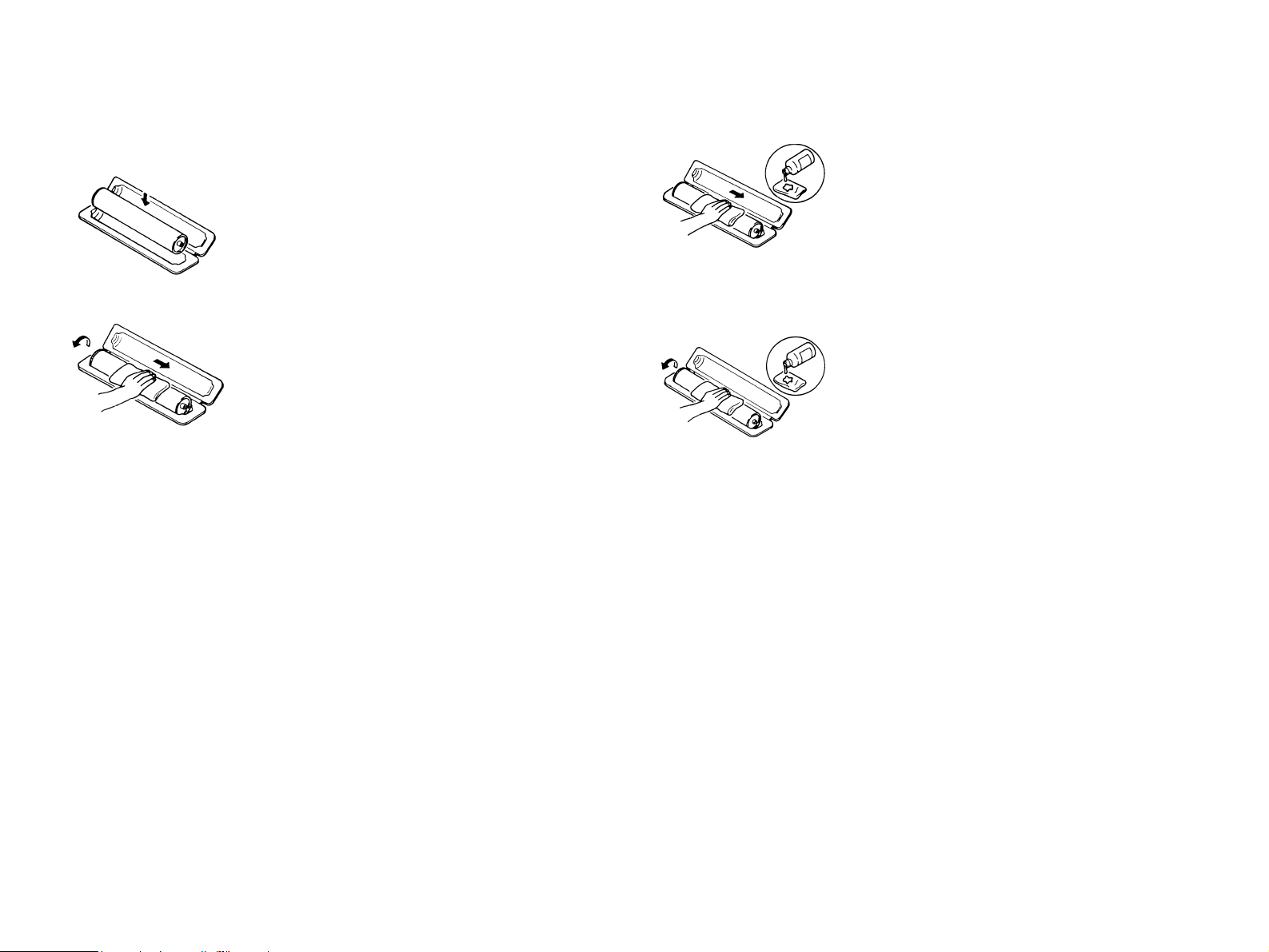
4.Precautions for Handling Batteries
(Lithium, Nickel-Cadmium, etc.)
Replace a rundown battery with the same type as specified
in the manufacturer's parts manual.
Before installing a new battery, make sure of the correct
polarity of the installation or the battery could burst.
Dispose of used batteries according to the local regulations.
Never dispose of them at the user's premises or attempt to
try to discharge one.
Page 8
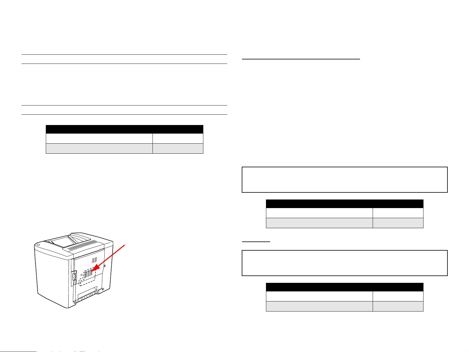
5.Precautions for the Laser Beam
(Only for Products Employing a Laser)
Removing the cover marked with the following caution label
could lead to possible exposure to the laser beam, resulting
in eye damage or blindness. Be sure to unplug the power
cord before removing this cover.
If removing this cover while the power is ON is unavoidable,
be sure to wear protective laser goggles that meet
specifications.
Make sure that no one enters the room when the machine is
in this condition.
When handling the laser unit, observe the “Precautions for
Handling Laser Equipment.”
Other Precautions
When handling circuit boards, observe the “HANDLING of PWBs”.
The PC Drum is a very delicate component. Observe the precautions
given in “HANDLING OF THE PC DRUM” because mishandling may
result in serious image problems.
Note that replacement of a circuit board may call for readjustments or
resetting of particular items, or software installation.
Page 9

Precautions for Service
When performing inspection and service procedures, observe the
following precautions to prevent mishandling of the machine and its
parts.
All troubleshooting procedures contained herein assume that
there are no breaks in the harnesses and cords and all
connectors are plugged into the right positions.
The procedures preclude possible malfunctions due to noise
and other external causes.
* Depending on the model, some of the precautions given in the
following do not apply.
PRECAUTIONS BEFORE SERVICE
When the user is using a word processor or personal computer from
a wall outlet of the same line, take necessary steps to prevent the
circuit breaker from opening due to overloads.
Never disturb the LAN by breaking or making a network connection,
altering termination, installing or removing networking hardware or
software, or shutting down networked devices without the
knowledge and express permission of the network administrator or
the shop supervisor.
HOW TO USE THIS BOOK
DIS/REASSEMBLY, ADJUSTMENT
To reassemble the product, reverse the order of disassembly
unless otherwise specified.
TROUBLESHOOTING
PRECAUTIONS FOR SERVICE
Check the area surrounding the service site for any signs of
damage, wear or need of repair.
Keep all disassembled parts in good order and keep tools under
control so that none will be lost or damaged.
After completing a service job, perform a safety check. Make sure
that all parts, wiring and screws are returned to their original
positions.
Do not pull out the toner hopper while the toner bottle is turning.
This could result in a damaged motor or locking mechanism.
If the product is to be run with the front door open, make sure that
the toner hopper is in the locked position.
Do not use an air gun or vacuum cleaner for cleaning the ATDC
Sensor and other sensors, as they can cause electrostatic
destruction. Use a blower brush and cloth. If a unit containing these
sensors is to be cleaned, first remove the sensors from the unit.
If a component on a PWB or any other functional unit including a
motor is defective, the text only instructs you to replace the
whole PWB or functional unit and does not give troubleshooting
procedures applicable within the defective unit.
Page 10

PRECAUTIONS FOR DISASSEMBLY/REASSEMBLY
PRECAUTIONS FOR CIRCUIT INSPECTION
Be sure to unplug the copier from the outlet before attempting to
service the copier.
The basic rule is not to operate the copier anytime during
disassembly. If it is absolutely necessary to run the copier with its
covers removed, use care not to allow your clothing to be caught in
revolving parts such as the timing belt and gears.
Before attempting to replace parts and unplug connectors, make
sure that the power cord of the copier has been unplugged from the
wall outlet.
Be sure to use the Interlock Switch Actuating Jig whenever it is
necessary to actuate the Interlock Switch with the covers left open
or removed.
While the product is energized, do not unplug or plug connectors
into the circuit boards or harnesses.
Never use flammable sprays near the copier.
A used battery should be disposed of according to the local
regulations and never be discarded casually or left unattended at
the user's premises.
When reassembling parts, make sure that the correct screws (size,
type) and toothed washer are used in the correct places.
Never create a closed circuit across connector pins except those
specified in the text and on the printed circuit.
When creating a closed circuit and measuring a voltage across
connector pins specified in the text, be sure to use the GND wire.
HANDLING OF PWBS
During Transportation/Storage:
During transportation or when in storage, new P.W. Boards must
not be indiscriminately removed from their protective conductive
bags.
Do not store or place P.W. Boards in a location exposed to
direct sunlight and high temperature.
When it becomes absolutely necessary to remove a Board from
its conductive bag or case, always place it on its conductive mat
in an area as free as possible from static electricity.
Do not touch the pins of the ICs with your bare hands.
Protect the PWBs from any external force so that they are not
bent or damaged.
During Inspection/Replacement:
If it becomes necessary to replace the thermal fuse or any other
fuse mounted on a board, be sure to use one of the rating marked
on the blown fuse. Always note the rating marked on the fuse, as
the rating and mounting site or number used are subject to change
without notice.
Avoid checking the IC directly with a multimeter; use connectors
on the Board.
Never create a closed circuit across IC pins with a metal tool.
Before unplugging connectors from the P.W. Boards, make sure
that the power cord has been unplugged from the outlet.
Page 11

When removing a Board from its conductive bag or conductive
case, do not touch the pins of the ICs or the printed pattern.
Place it in position by holding only the edges of the Board.
When touching the PWB, wear a wrist strap and connect its cord
to a securely grounded place whenever possible. If you cannot
wear a wrist strap, touch a metal part to discharge static
electricity before touching the PWB.
HANDLING OF THE PC DRUM
* Only for Products Not Employing an Imaging Cartridge.
During Transportation/Storage:
Use the specified carton whenever moving or storing the PC
Drum.
Note that replacement of a PWB may call for readjustments or
resetting of particular items.
HANDLING OF OTHER PARTS
The magnet roller generates a strong magnetic field. Do not bring it
near a watch, floppy disk, magnetic card, or CRT tube.
The storage temperature is in the range between -20°C and
+40°C.
In summer, avoid leaving the PC Drum in a car for a long time.
Handling:
Ensure that the correct PC Drum is used.
Whenever the PC Drum has been removed from the copier,
store it in its carton or protect it with a Drum Cloth.
The PC Drum exhibits greatest light fatigue after being exposed
to strong light over an extended period of time. Never, therefore,
expose it to direct sunlight.
Use care not to contaminate the surface of the PC Drum with oil-
base solvent, fingerprints, and other foreign matter.
Do not scratch the surface of the PC Drum.
Do not apply chemicals to the surface of the PC Drum.
Do not attempt to wipe clean the surface of the PC Drum.
Page 12
If, however, the surface is contaminated with fingerprints, clean it using
the following procedure.
1. Place the PC Drum into one half of its carton.
3. Soak a small amount of either ethyl alcohol
or isopropyl alcohol into a clean, unused
Dust-Free Cotton Pad which has been
folded over into quarters. Now, wipe the
surface of the PC Drum in one continuous
movement from its rear edge to its front
edge and off its surface one to two times.
2. Gently wipe the residual toner off the
surface of the PC Drum with a dry, DustFree Cotton Pad.
A.Turn the PC Drum so that the area of its
surface on which the line of toner left by the
Cleaning Blade is present is facing straight
up. Wipe the surface in one continuous
movement from the rear edge of the PC
Drum to the front edge and off the surface
of the PC Drum.
B. Turn the PC Drum slightly and wipe the
newly exposed surface area with a CLEAN
face of the Dust-Free Cotton Pad. Repeat
this procedure until the entire surface of the
PC Drum has been thoroughly cleaned.
*At this time, always use a CLEAN face of the dry
Dust-Free Cotton Pad until no toner is evident on
the face of the Pad after wiping.
*Never move the Pad back and forth.
4. Using the SAME face of the Pad, repeat the
procedure explained in the latter half of
step 3 until the entire surface of the PC
Drum has been wiped. Always OVERLAP
the areas when wiping. Two complete turns
of the PC Drum would be appropriate for
cleaning.
NOTE:
Even when the PC Drum is only locally dirtied, wipe the entire
surface.
Do not expose the PC Drum to direct sunlight. Clean it as
quickly as possible even under interior illumination.
If dirt remains after cleaning, repeat the entire procedure from
the beginning one more time.
Page 13

HANDLING OF THE IMAGING CARTRIDGE
* Only for Products Employing an Imaging Cartridge.
During Transportation/Storage:
The storage temperature is in the range between -20°C and
+40°C.
In summer, avoid leaving the Imaging Cartridge in a car for a
long time.
Handling:
Store the Imaging Cartridge in a place that is not exposed to
direct sunlight.
Precautionary Information on the PC Drum Inside the Imaging
Cartridge:
Use care not to contaminate the surface of the PC Drum with oil-
base solvent, fingerprints, and other foreign matter.
Do not scratch the surface of the PC Drum.
Do not attempt to wipe clean the surface of the PC Drum.
W A R N I N G
WARNING
Do not throw the toner cartridge or toner into an open
flame. The hot toner may scatter and cause burns or
other damage.
Page 14
SAFETY INFORMATION
LASER SAFETY
This is a digital machine certified as a class 1 laser product. There is no
possibility of danger from a laser, provided the machine is serviced
according to the instruction in this manual.
INTERNAL LASER RADIATION
semiconductor laser
Maximum average radiation power(*) 4.68 µW
Wavelength 770-795 nm
*:Laser Aperture of the Print Head Unit
This product employs a Class 3b laser diode that emits an invisible
laser beam. The laser diode and the scanning polygon mirror are
incorporated in the print head unit.
The print head unit is NOT A FIELD SERVICE ITEM. Therefore, the
print head unit should not be opened under any circumstances.
the U.S.A., Canada (CDRH Regulation)
This machine is certified as a Class I Laser product under
Radiation Performance Standard according to the Food, Drug
and Cosmetic Act of 1990. Compliance is mandatory for Laser
products marketed in the United States and is reported to the
Center for Devices and Radiological Health (CDRH) of the U.S.
Food and Drug Administration of the U.S. Department of Health
and Human Services (DHHS). This means that the device does
not produce hazardous laser radiation.
The label shown to page 15 indicates compliance with the
CDRH regulations and must be attached to laser products
marketed in the United States.
CAUTION
Use of controls, adjustments or performance of procedures other than those
specified in this manual may result in hazardous radiation exposure.
semiconductor laser
Maximum power of the laser diode 5 mW
Wavelength 770-795 nm
Laser Aperture of the Print Head Unit
All Areas
CAUTION
Use of controls, adjustments or performance of procedures other than those
specified in this manual may result in hazardous radiation exposure.
semiconductor laser
Maximum power of the laser diode 5 mW
Wavelength 770-795 nm
Page 15

Denmark
Finland, Sweden
ADVARSEL
Usynlig laserstråling ved åbning, når sikkerhedsafbrydere er ude af funktion.
Undgå udsættelse for stråling. Klasse 1 laser produkt der opfylder IEC60825
sikkerheds kravene.
halvlederlaser
Laserdiodens højeste styrke 5 mW
bølgelængden 770-795 nm
Norway
ADVERSEL
Dersom apparatet brukes på annen måte enn spesifisert i denne
bruksanvisning, kan brukeren utsettes för unsynlig laserstrålning, som
overskrider grensen for laser klass 1.
halvleder laser
Maksimal effekt till laserdiode 5 mW
bølgelengde 770-795 nm
LUOKAN 1 LASERLAITE
KLASS 1 LASER APPARAT
VAROITUS!
Laitteen käyttäminen muulla kuin tässä käyttöohjeessa mainitulla tavalla
saattaa altistaa käyttäjän turvallisuusluokan 1 ylittävälle näkymättömälle
lasersäteilylle.
puolijohdelaser
Laserdiodin suurin teho 5 mW
aallonpituus 770-795 nm
VARNING!
Om apparaten används på annat sätt än i denna bruksanvisning
specificerats, kan användaren utsättas för osynlig laserstrålning, som
överskrider gränsen för laserklass 1.
halvledarlaser
Den maximala effekten för laserdioden 5 mW
våglängden 770-795 nm
VARO!
Avattaessa ja suojalukitus ohitettaessa olet alttiina näkymättomälle
lasersäteilylle. Älä katso säteeseen.
VARNING!
Osynlig laserstråining när denna del är öppnad och spärren är urkopplad.
Betrakta ej stråien.
Page 16
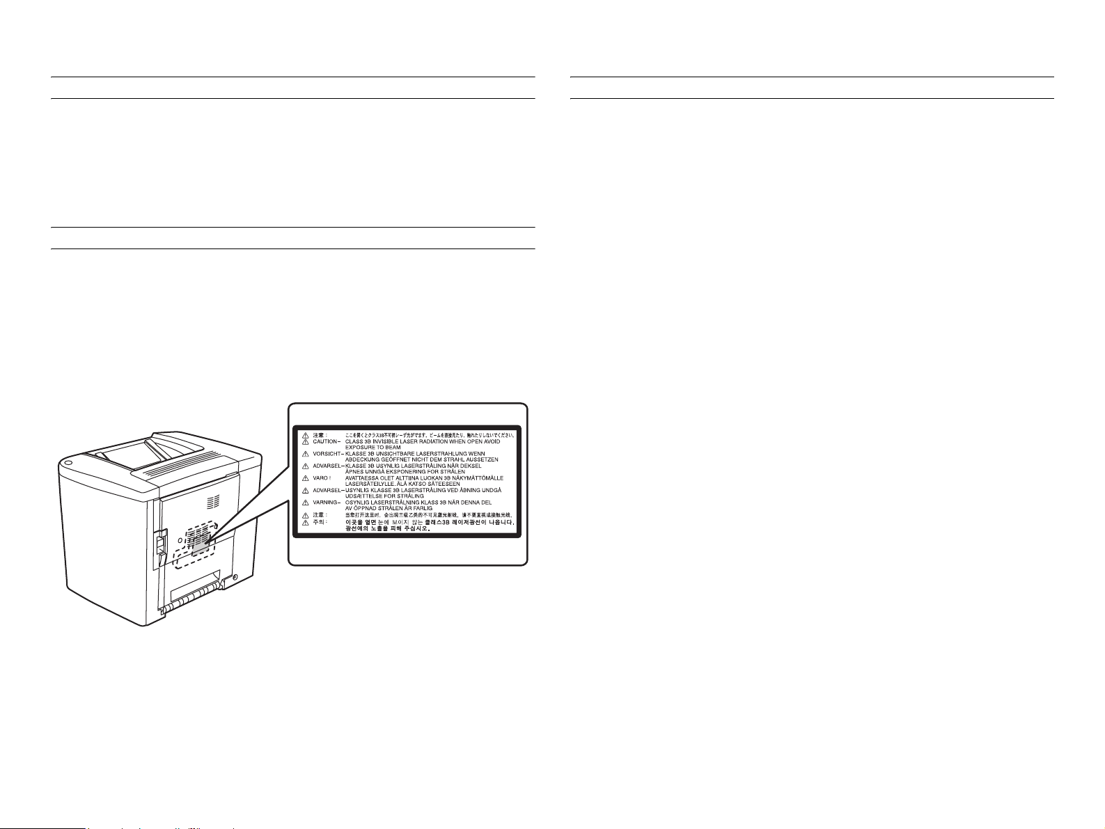
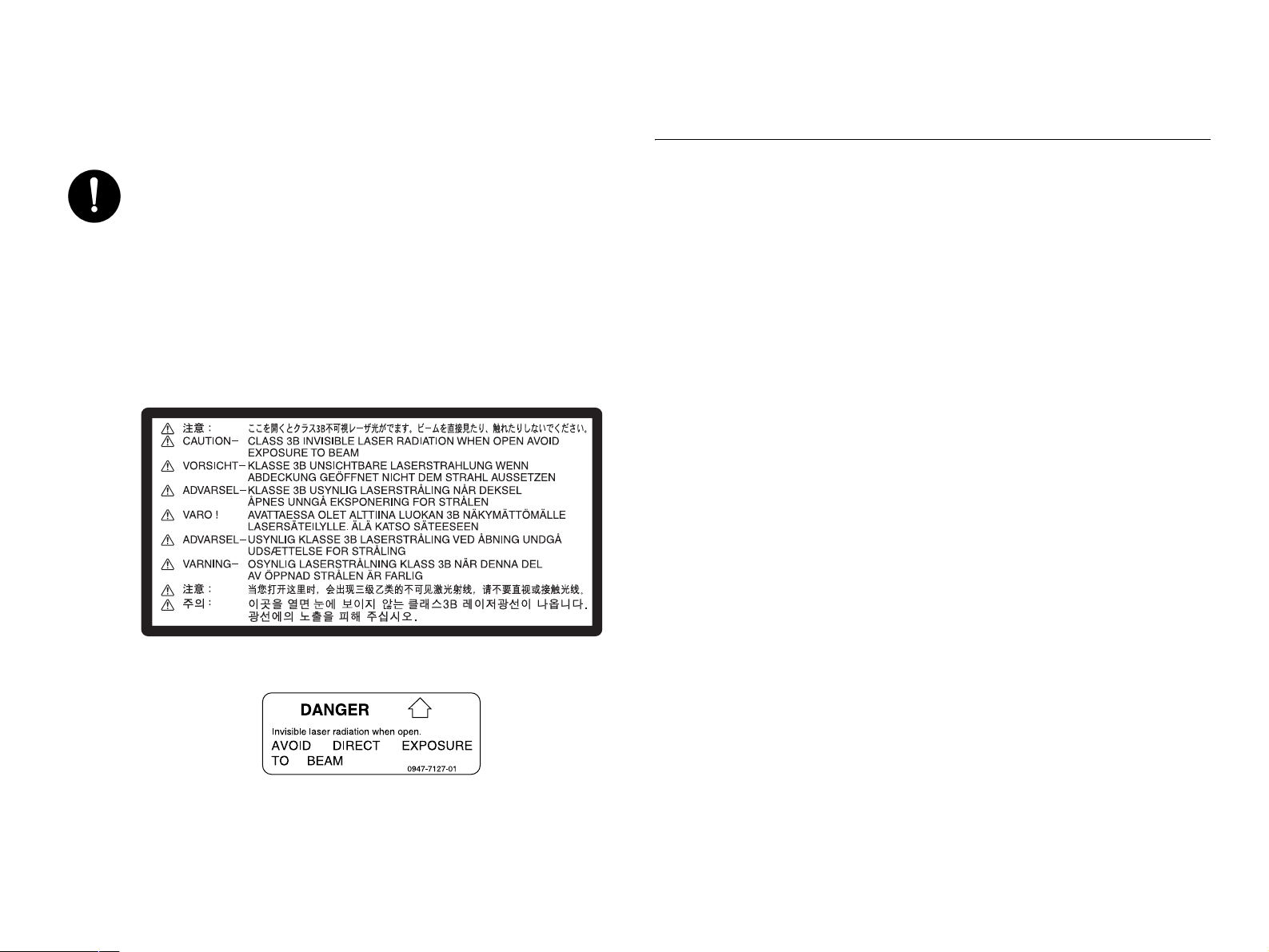
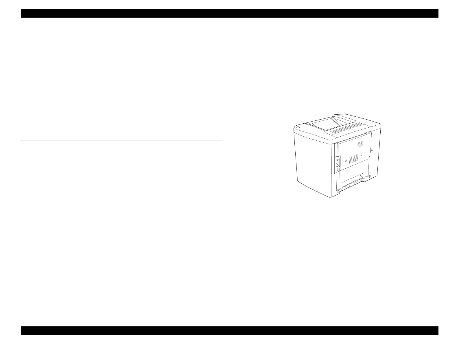
LASER SAFETY LABEL
PRECAUTIONS FOR HANDLING THE LASER EQUIPMENT
A laser safety label is attached to the outside of the machine as shown
below.
LASER CAUTION LABEL
A laser caution label is attached to the inside of the machine as shown
below.
When laser protective goggles are to be used, select ones with a
lens conforming to the above specifications.
When a disassembly job needs to be performed in the laser beam
path, such as when working around the printerhead and PC Drum,
be sure first to turn the printer OFF.
If the job requires that the printer be left ON, take off your watch and
ring and wear laser protective goggles.
A highly reflective tool can be dangerous if it is brought into the laser
beam path. Use utmost care when handling tools on the user's
premises.
Page 17

Revision Status
Revision Date of Issue Description
0 June 3, 2002 Partial release (Chapter 1/ Chapter4) (provisional)
A September 30, 2002 First release
Page 18

EPSON AcuLaser C1900/AcuLaser C900 Revision A
Contents
Chapter 1 Product Description
1.1 Product Description............................................................................................. 22
1.1.1 Features....................................................................................................... 22
1.2 Basic Specifications............................................................................................. 24
1.2.1 Process Specifications ................................................................................ 24
1.2.2 Printer Basic Specifications........................................................................ 24
1.2.3 Paper Specifications.................................................................................... 30
1.2.3.1 Paper type ............................................................................................ 30
1.2.3.2 Paper Feeding ...................................................................................... 31
1.2.3.3 Printing Area ....................................................................................... 31
1.2.4 Reliability and Maintainability ................................................................... 32
1.2.4.1 Reliability ............................................................................................ 32
1.2.4.2 Durability............................................................................................. 33
1.2.4.3 Maintenance ........................................................................................ 33
1.2.5 Operating Conditions (Including Consumables) ........................................ 33
1.2.6 Storage and Transport Environments of the Packaged Printer Main Unit and
Optional Products ...................................................................................... 35
1.2.7 Electrical Feature........................................................................................ 35
1.2.8 Compatible Standard .................................................................................. 36
1.2.9 Consumable / Regular Replacement Component Specifications ............... 37
1.2.9.1 Specifications ...................................................................................... 37
1.2.9.2 Storage and Transport Environments for Packages ............................ 38
1.2.9.3 Lives of Components........................................................................... 39
1.3 Controller Unit Specifications............................................................................. 41
1.3.1 Controller Basic Specifications .................................................................. 41
1.3.2 Differences in Jumper Settings between Designated Markets ................... 42
1.3.3 External I/F Specifications ......................................................................... 42
1.3.3.1 Parallel Interface Specifications.......................................................... 43
1.3.3.2 USB Interface Specifications .............................................................. 44
1.3.3.3 Ethernet Interface Specifications (AcuLaser C1900).......................... 45
1.3.3.4 Type B Interface Specifications .......................................................... 46
1.4 Control Panel....................................................................................................... 47
1.4.1 External Appearance and Names of Parts .................................................. 47
1.4.2 List of Panel Settings (Only with AcuLaser C1900).................................. 49
1.4.3 Explanation of Each Setting Menu and Items
(Only with AcuLaser C1900) .................................................................... 56
1.4.4 Special Operations (Only with AcuLaser C1900)...................................... 58
1.4.5 Printer Setting Items (Only with AcuLaser C900) ..................................... 59
1.4.5.1 Setting Items stored on the Printer Side .............................................. 59
1.4.5.2 Setting Items which are Valid only in the Job and are not
Stored in Printer................................................................................... 60
1.4.5.3 Setting Items Requiring Control by the Printer for
Each Printing or Status Change ........................................................... 62
1.4.5.4 Settings controlled by the mechanical controller, but requiring reading out
and changing the values....................................................................... 64
1.4.5.5 Settings specified regardless of Job and not stored in the printer ....... 65
1.4.6 Special Setting Operation (Only with AcuLaser C900) ............................. 66
1.4.7 Printer Status Checking .............................................................................. 69
1.4.7.1 Status sheet.......................................................................................... 69
1.4.8 Reserve Job List (Only for AcuLaser C1900)............................................ 72
1.4.9 Form Overlay List (Only for AcuLaser C1900)......................................... 72
1.4.10 Network Status Sheet (Only for AcuLaser C1900) .................................. 73
1.4.11 Engine Status Sheet .................................................................................. 75
1.5 RAM Expansion.................................................................................................. 79
1.6 Handling Precautions .......................................................................................... 80
1.6.1 Caution when there is a Power Failure....................................................... 80
1.6.2 Caution Regarding High Temperature Parts .............................................. 80
1.7 Network Environment (Only for AcuLaser C900).............................................. 81
1.8 Host Requirements (Only for AcuLaser C900)................................................... 82
1.9 AIDC Control...................................................................................................... 82
1.10 External Appearance and Parts Name............................................................... 83
1.10.1 Overall Dimensions .................................................................................. 83
1.10.2 Names of Parts.......................................................................................... 84
1.11 Differences in Specifications............................................................................. 85
1.11.1 Differences between AcuLaser C1900 and AcuLaser C2000.................. 85
1.11.2 Differences between AcuLaser C900 and AcuLaser C1000.................... 86
18
Page 19

EPSON AcuLaser C1900/AcuLaser C900 Revision A
Chapter 2 Operating Principles
2.1 Mechanism Overview.......................................................................................... 88
2.1.1 Locations of Electric Parts.......................................................................... 89
2.2 Operation Sequence............................................................................................. 92
2.3 Image Stabilization Control................................................................................. 93
2.3.1 Execution Conditions for Image Stabilization Control (Only for AcuLaser
C900) ......................................................................................................... 95
2.3.2 Engine Restrictions..................................................................................... 96
2.4 Description of Mechanisms................................................................................. 97
2.4.1 Paper Path ................................................................................................... 97
2.4.2 Photoconductor Unit................................................................................... 98
2.4.2.1 OPC Drum........................................................................................... 98
2.4.2.2 Charging Process................................................................................. 99
2.4.3 Exposure Process...................................................................................... 100
2.4.4 Development Process................................................................................ 101
2.4.4.1 Toner Cartridge Rack ........................................................................ 101
2.4.4.2 Development Position ....................................................................... 102
2.4.4.3 Toner Cartridge ................................................................................. 103
2.4.5 Transfer Process........................................................................................ 105
2.4.5.1 Transfer Belt Unit.............................................................................. 105
2.4.5.2 Secondary Transfer Roller Cleaning ................................................. 106
2.4.5.3 Transfer Belt Cleaner Mechanism..................................................... 107
2.4.5.4 Waste Toner Box............................................................................... 108
2.4.5.5 Waste Toner Box Detection .............................................................. 108
2.4.6 Fusing Process .......................................................................................... 109
2.4.6.1 Fuser Unit.......................................................................................... 109
2.4.7 Fusing Temperature Control..................................................................... 110
2.4.8 Paper Feed Mechanism............................................................................. 112
2.4.8.1 MP Tray............................................................................................. 112
2.4.8.2 500-sheet Cassette Unit (Option) ...................................................... 113
2.4.9 Other Mechanisms.................................................................................... 114
2.4.9.1 Duplex Unit (option) ......................................................................... 114
2.5 Controller Board Operating Principles.............................................................. 117
Chapter 3 Troubleshooting
3.1 Overview ........................................................................................................... 122
3.2 Status Display (AcuLaser C1900)..................................................................... 123
3.2.1 Service Call Error Status .......................................................................... 123
3.2.1.1 Details of Service Call Errors and Remedy ...................................... 124
3.2.2 Printer Status............................................................................................. 130
3.2.3 Details of Status Messages and Treatment Method.................................. 132
3.2.4 Details of Error Status and Remedy ......................................................... 134
3.2.5 Details of Warning Status and Remedy.................................................... 139
3.3 Status Display (AcuLaser C900)....................................................................... 142
3.3.1 Service Call Error Status .......................................................................... 142
3.3.1.1 Details of Service Call Errors and Remedy ...................................... 144
3.3.2 Printer Status............................................................................................. 150
3.3.3 Details of Status Messages and Treatment Method.................................. 151
3.3.4 Details of Error Status and Remedy ......................................................... 152
3.3.5 Details of Warning Status and Remedy.................................................... 155
3.4 Check Points and Remedy for Paper Jam ......................................................... 158
3.4.1 Initial Checking ........................................................................................ 158
3.4.2 Locations of Jam Detection Sensors......................................................... 158
3.4.3 Jam Detection Timing / Action to be Taken............................................. 159
3.4.4 Checking Method for Electric Parts ......................................................... 161
3.5 Details of Print Quality Trouble and Remedy................................................... 163
Chapter 4 Disassembly and Assembly
4.1 Overview ........................................................................................................... 166
4.1.1 Precautions................................................................................................ 166
4.1.2 Tools ......................................................................................................... 168
4.1.3 Screws....................................................................................................... 168
4.2 Main Unit Disassembly..................................................................................... 169
4.2.1 Before Disassembling the Printer ............................................................. 171
4.2.1.1 Toner Cartridge Removal.................................................................. 171
4.2.1.2 Removal of Other Units .................................................................... 172
4.3 Periodical Replacement Parts Removal ............................................................ 174
4.3.1 Secondary Transfer Roller........................................................................ 174
4.3.2 Fuser Unit ................................................................................................. 174
4.4 Cover Removal.................................................................................................. 176
4.4.1 Upper Front Cover.................................................................................... 176
4.4.2 Top Cover................................................................................................. 176
4.4.3 Front Door ................................................................................................ 177
4.4.4 Rear Cover................................................................................................ 177
4.4.5 Upper Rear Cover..................................................................................... 177
4.4.6 Left Cover................................................................................................. 178
19
Page 20

EPSON AcuLaser C1900/AcuLaser C900 Revision A
4.4.7 Front Cover............................................................................................... 178
4.4.8 Right Door ................................................................................................ 179
4.5 Printer Main Parts Disassembly and Assembly................................................. 182
4.5.1 Main Board (C485MAIN/C494MAIN).................................................... 182
4.5.2 Engine Board (PWB-A)............................................................................ 183
4.5.3 Exhaust Fan Motor (M6) .......................................................................... 184
4.5.4 Power Supply Fan Motor (M4)................................................................. 184
4.5.5 Power Supply Unit (PU)........................................................................... 185
4.5.6 AIDC Sensor............................................................................................. 186
4.5.7 High Voltage Unit (HV) ........................................................................... 187
4.5.8 Cleaner Pressure Flapper Solenoid (SL4)................................................. 188
4.5.9 Rack Motor (M2)...................................................................................... 189
4.5.10 Main Motor Ass’y................................................................................... 190
4.5.11 Multi Purpose Tray................................................................................. 191
4.5.12 Paper Empty Sensor................................................................................ 192
4.5.13 Fuser Unit Removal................................................................................ 193
4.5.14 Fusing Cooling Fan Motor (M5) ............................................................ 195
4.5.15 Paper Load Roller................................................................................... 196
4.5.16 Separation Roller .................................................................................... 196
4.5.17 Printer Head Unit (PH) ........................................................................... 197
4.5.18 Manual Paper Feed Solenoid (SL1)........................................................ 199
4.5.19 Fuser Deceleration Drive Assy............................................................... 200
4.5.20 Rack ........................................................................................................ 201
4.6 Extension Unit Disassembly and Assembly...................................................... 203
4.6.1 The 2nd Paper Load Roller....................................................................... 203
4.6.2 500-sheet Cassette Unit Control Board (PWB-A).................................... 204
4.7 Duplex Unit Disassembly and Assembly.......................................................... 205
4.7.1 Duplex Unit Control Board (PWB-A)...................................................... 205
4.7.2 Paper Feed Sensor..................................................................................... 205
4.7.3 Reverse Motor / Transfer Motor............................................................... 206
5.3.1 Overview .................................................................................................. 211
5.3.1.1 Operating Environment ..................................................................... 211
5.3.1.2 Conditions for Use ............................................................................ 211
5.3.2 How to Use the Service Utility................................................................. 212
5.3.2.1 Starting the Service Utility ................................................................ 212
5.3.2.2 Functions ........................................................................................... 214
5.3.3 Operation .................................................................................................. 214
5.3.3.1 Engine Status Sheet........................................................................... 214
5.3.3.2 Reset Counter .................................................................................... 214
5.3.3.3 USB ID.............................................................................................. 215
Chapter 6 Maintenance
6.1 Maintenance ...................................................................................................... 217
6.1.1 Consumables and Regular Replacement Parts ......................................... 217
6.1.2 Cleaning.................................................................................................... 217
Chapter 7 Appendix
7.1 Schematic Wiring Diagram............................................................................... 219
7.2 Connectors and Jumpers on Circuit Boards ...................................................... 220
7.3 ASP List ............................................................................................................ 248
7.4 Circuit Diagram................................................................................................. 258
Chapter 5 Adjustment
5.1 Overview ........................................................................................................... 208
5.2 USB ID Input..................................................................................................... 209
5.2.1 Installation Procedure for Program........................................................... 209
5.2.2 Procedure for Program Operation............................................................. 209
5.2.3 USB ID Confirmation............................................................................... 210
5.3 Service Utility (AcuLaser C900)....................................................................... 211
20
Page 21

PRODUCT DESCRIPTION
CHAPTER
1
Page 22

EPSON AcuLaser C1900/AcuLaser C900 Revision A
1.1 Product Description
AcuLaser C1900/AcuLaser C900 are non-impact color page printer that takes
advantage of the laser and electrophotographic technology.
1.1.1 Features
ENGINE FEATURES
True 600 dpi high resolution full color printing engine. (AcuLaser C900)
New, low-price color engine supporting A4-size paper (AcuLaser C1900)
4.0 ppm (A4 color) /16.0 ppm (A4 monochrome) print speed.
Duplex printing supported (A4/LT).
Compact and light weight, with body size about 70%, weight about 65%, and foot
print about 85% of AcuLaser C2000
Resolution
AcuLaser C1900 : 600dpi
AcuLaser C900 : 600dpi / 300dpi
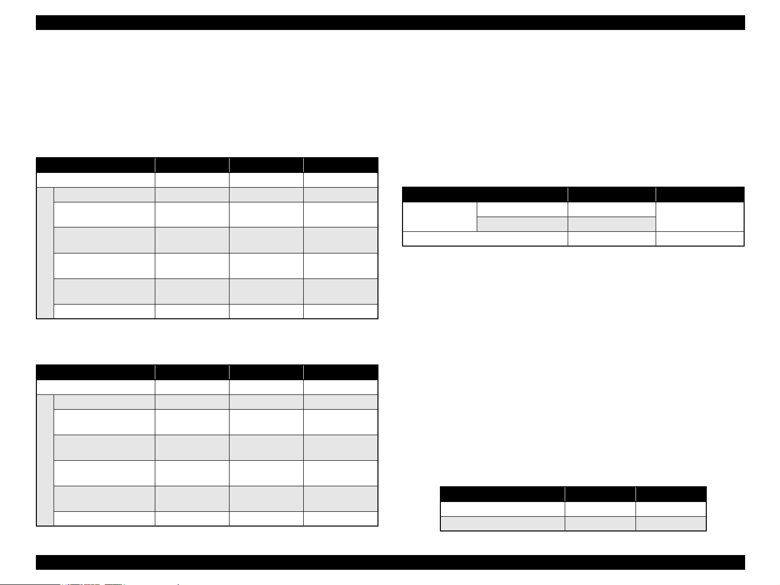
Paper feed
Table 1-1. Paper feed
Postcards,
Model Standard paper feed
AcuLaser
C1900
AcuLaser
C900
MP Tray (200 sheets) -
MP tray (200 sheets) MP tray (50 sheets)
Transparencies, Thick
Paper, or Labels
A maximum of 200 sheets can be output face-down.
Optional (Lower Cassette Unit)
Paper Source (500 sheets)
An optional paper cassette unit
(500 sheet, A4/LT only)
option
1.5 K pre-installed toner
1.5 K toner for each color included with package
4.5 K toner for Optional use
CONTROLLER FEATURES
<AcuLaser C1900>
New RISC CPU: PowerPC 300 MHz (SPC603ei)
RAM: Standard 32MB
Expandable up to a maximum of 1GB
SDRAM DIMM supporting standard PC100 and PC133 (32, 64, 128, 256, or
512 MB) can be used. For memory expansion of 544 MB or more, the standard
32 MB DIMM must be replaced.
Color technologies
AcuLaser Color Halftoning installed
Three types of standard interfaces installed
10/100baseTx Ethernet
IEEE1284 parallel interface (Compatibility, Nibble, ECP)
USB 1.1 (2.0 FS 12Mbps Certified)
NOTE:
Support for optional Type-B interface
RAM expansion can increase the performance and speed of the AcuLaser Color
Halftoning drawing area, print speed, resolution, receive buffer size, and collated
printing (Collate in Printer).
HDD (optional) can be installed
New HDD that is also used by AcuLaser C8600 is supported.
(The old type of HDD cannot be used)
Improved color stability brought by new AIDC control Color stability matching or
exceeding AcuLaser C1000 is targeted.
Low noise level (target)
Sleep Mode : 39dB (A)
While printing : 54dB (A)
Use of newly developed polymerized toner, making oil-less fixing possible
Product Description Product Description 22
Page 23
EPSON AcuLaser C1900/AcuLaser C900 Revision A
<AcuLaser C900>
Host based controller
CPU: VR4305-48MHz
Standard RAM: 16 MB,
with additional RAM DIMM expanding to a maximum of 144 MB
Color technologies
CPGI, CRIT (Color RIT) installed
Two types of standard interfaces installed
IEEE1284 compatible parallel interface supporting ECP
USB I/F
SOFTWARE FEATURE
<AcuLaser C1900>
Emulation included as standard
ESC/Page Color mode
LJ4, GL2, ESC/P2, FX, I239X, ESC/Page (monochrome mode)
Optional emulation
Adobe PostScript 3
<AcuLaser C900>
ESC/PageS installed
Color supported
Duplex printing supported
Network compatibility
Use of background job commands establish network connections.
Ability to update the firmware
Supply of program on Flash DIMM makes update of firmware possible
(no MASK during mass production).
Figure 1-1. External Appearance
Ability to update the engine controller program.
This function is only supported for the evaluation sample.
DCC command support.
Diag command only.
Product Description Product Description 23
Page 24

EPSON AcuLaser C1900/AcuLaser C900 Revision A
1.2 Basic Specifications
1.2.1 Process Specifications
Printer formula
Semi-conductor laser beam scan and elector photography with dry single
component no electromagnetic toner.
Light Source
Semi-conductor laser
Photoconductor Unit
OPC (organic photoconductive conductor) drum
Charging
Needle electrode scorotron charger
Development
Exposed area development
Toner
Nonmagnetic one-component toner
Primary Transfer
Electrode roller transfer method
Intermediate Transfer
Intermediate transfer belt method
1.2.2 Printer Basic Specifications
Resolution
600 dpi
Warming Up Time
100 V, 120 V : 180 seconds or less (in 23 °C 55%RH, rated voltage)
220~240 V : 180 seconds or less (in 23 °C 55%RH, rated voltage)
Printing Mode
B/W mode : A regular monochrome mode that prints fastest.
Color mode : A color mode that uses Y, M, C, K toners.
Speed Mode
Standard mode : Paper feeding at the main unit's fastest speed.
Low-speed <1> mode : Reduce the envelope feeding speed to retain the
quality.
Low-speed <2> mode : Reduces paper feeding speed to ensure satisfactory
fusing at printing on thick paper, label sheets or
coated paper exceeding 90g/m
Low-speed <3> mode : Reduce the paper feeding speed to retain the fixity of
printing on transparencies.
2
(24 lb).
Secondary Transfer
Roller transfer method
Fixing
Heated roller fuser method
Density Adjustment
Automatic adjustment (not adjustable by user)
Product Description Basic Specifications 24
Page 25
EPSON AcuLaser C1900/AcuLaser C900 Revision A
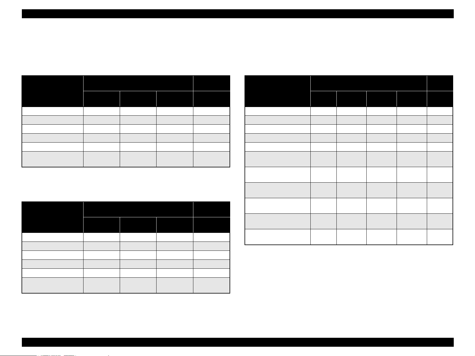
First Printing Time
*1
B/W mode
Table 1-2. First Printing Time (Unit: seconds max.)
Printing mode
\
Paper size
A4 14.0 23.0 28.0 25.0
A5 14.0 23.0 - -
B5 14.0 23.0 - -
Letter 14.0 23.0 28.0 25.0
Japanese official postcard - 22.0 - -
Japanese official returned
postcard
Standard
mode
- 23.0 - -
Simplex printing
Low-speed
<2> mode
Low-speed
<3> mode
Duplex
printing
Standard
mode
Color mode
Table 1-3. First Printing Time (Unit: seconds max.)
Printing mode
\
Paper size
A4 25.0 34.0 40.0 39.0
A5 25.0 34.0 - -
B5 25.0 34.0 - -
Letter 25.0 34.0 40.0 39.0
Japanese official postcard - 33.0 - -
Japanese official returned
postcard
Standard
mode
- 34.0 - -
Simplex printing
Low-speed
<2> mode
Low-speed
<3> mode
Duplex
printing
Standard
mode
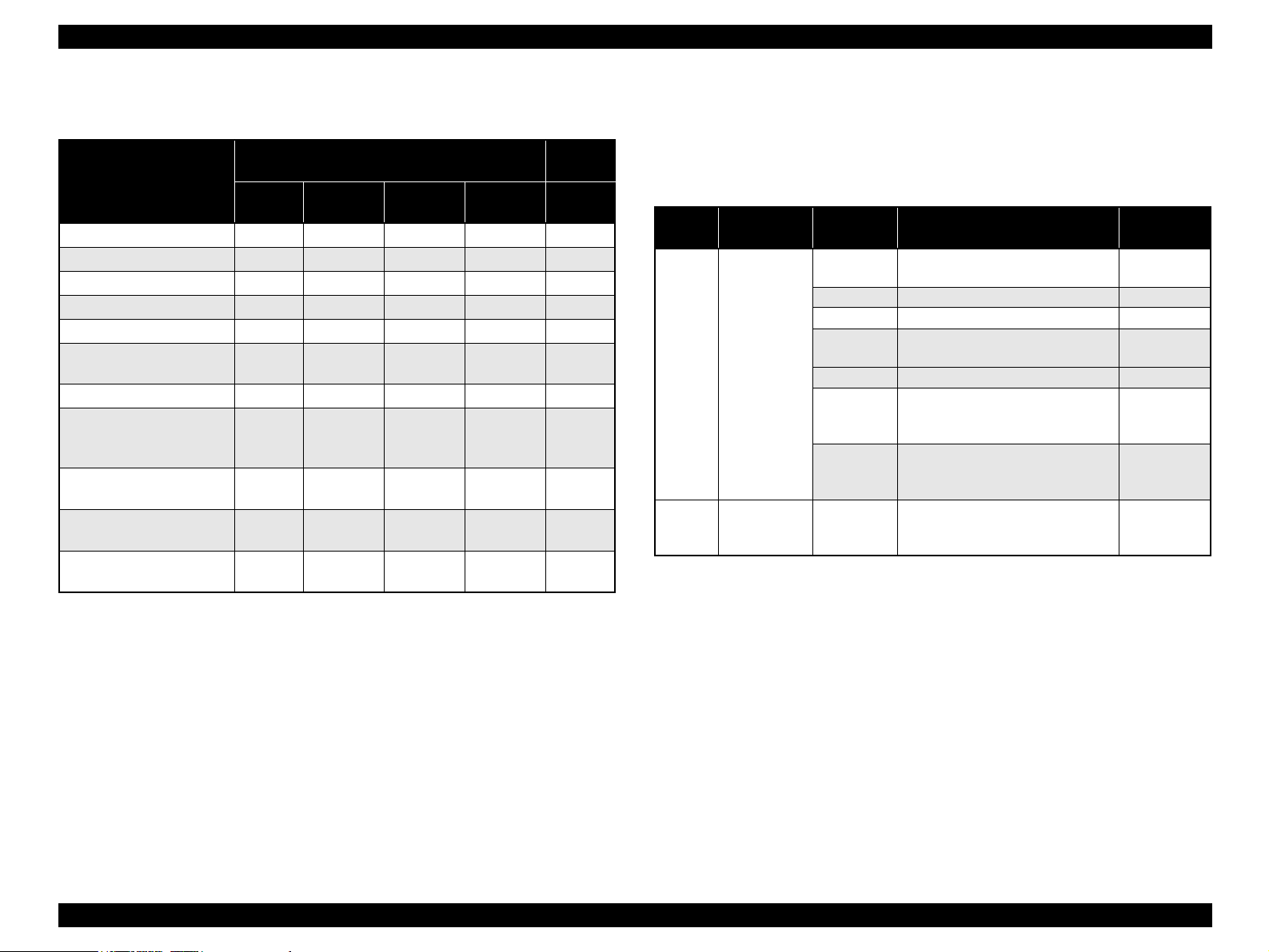
Continuous Printing Speed
B/W mode
Table 1-4. Continuous Printing Speed (Unit: ppm)
*2
*2
Printing mode
\
Paper size
A4 16.0 - 3.3 2.5 10.0
A5 16.0 - 3.5 - -
B5 16.0 - 3.4 - -
Letter 16.0 - 3.3 2.5 10.0
Japanese official postcard - - 3.6 - -
Japanese official returned
postcard
Envelope C6 Yokei #6
/MON/DL
Envelope Yokei #0
/Yokei #4
User defined
148 mm ≤ L<210 mm
User defined
210 mm ≤ L ≤ 297 mm
User defined
297 mm <L ≤ 356 mm
Note *: JIS envelope
NOTE 1:
*
C5/Com-#10
L: Paper length
2:
Paper width is between 92 mm and 216 mm
Standard
mode
- - 3.5 - -
*
-4.1 - - -
- 4.0 - - -
- - 3.5 - -
16.0 - 3.3 - -
8.0----
Simplex printing
Low-speed
<1> mode
Low-speed
<2> mode
Low-speed
<3> mode
Duplex
printing
Standard
mode
Note *1: The above values are periods from when the printer receives the start command to
when it completes ejecting the first sheet.
*2: The above periods are the same in all the paper feed bins.
Product Description Basic Specifications 25
Page 26
EPSON AcuLaser C1900/AcuLaser C900 Revision A
Color mode
Table 1-5. Continuous Printing Speed (Unit: ppm)
Printing mode
\
Paper size
A4 4.0 - 2.0 1.6 4.0
A5 4.0 - 2.0 - -
B5 4.0 - 2.0 - -
Letter 4.0 - 2.0 1.6 4.0
Japanese official postcard - - 2.1 - -
Japanese Official both-way
postcard
Envelope C6 - 2.3 - - -
Envelope MON/C5/Com#10/DL Yokei #0*/Yokei #4*
Yokei #6
User defined
148 mm
User defined
210 mm ≤ L ≤ 297 mm
User defined
297 mm < L ≤ 356 mm 2.0
*
≤ L<210 mm
Standard
mode
- - 2.0 - -
- 2.2 - - -
- - 2.0 - -
4.0 - 2.0 - -
2.0 - - - -
Simplex printing
Low-speed
<1> mode
Low-speed
<2> mode
Low-speed
<3> mode
Duplex
printing
Standard
mode
Paper Feed Reference
Centerline reference for each paper size, and for both the MP tray and optional
cassette unit (option).
Paper Feed
Table 1-6. Paper Feed
Paper source
Standard MP tray 200 sheets
Optional Optional
500sheets
cassette unit
Note *: JIS envelope
Capacity
(Height)
(23mmMax)
50 sheets Transparency: A4, Letter 50 sheets Label: A4, Letter -
50 sheets
50 sheets Label: A4, Letter -
10 sheets
50 sheets
500 sheets
(57mmMax)
Paper size for paper feed
A4,A5,B5,Letter,GLT,HLT,Exective Plain paper
Thick paper:
A4,A5,B5,Letter,GLT,HLT,Exective
Envelope:
C5, C6, Com-10, DL, Monarch,
Yokei #0
Postcard (for domestic models):
Japanese official postcard,
Japanese official returned postcard
A4 or Letter
(fixed on the factory default) 60 ~ 90 g/m
*
,Yokei #4 *,Yokei #6
*
Applicable
paper type
60 ~ 90 g/m
91 ~ 163 g/m
-
190 g/m
2
2
2
2
Note *: JIS envelope
NOTE 1:
L: Paper length
2:
Paper width is between 92 mm and 216 mm
Product Description Basic Specifications 26
Page 27
EPSON AcuLaser C1900/AcuLaser C900 Revision A
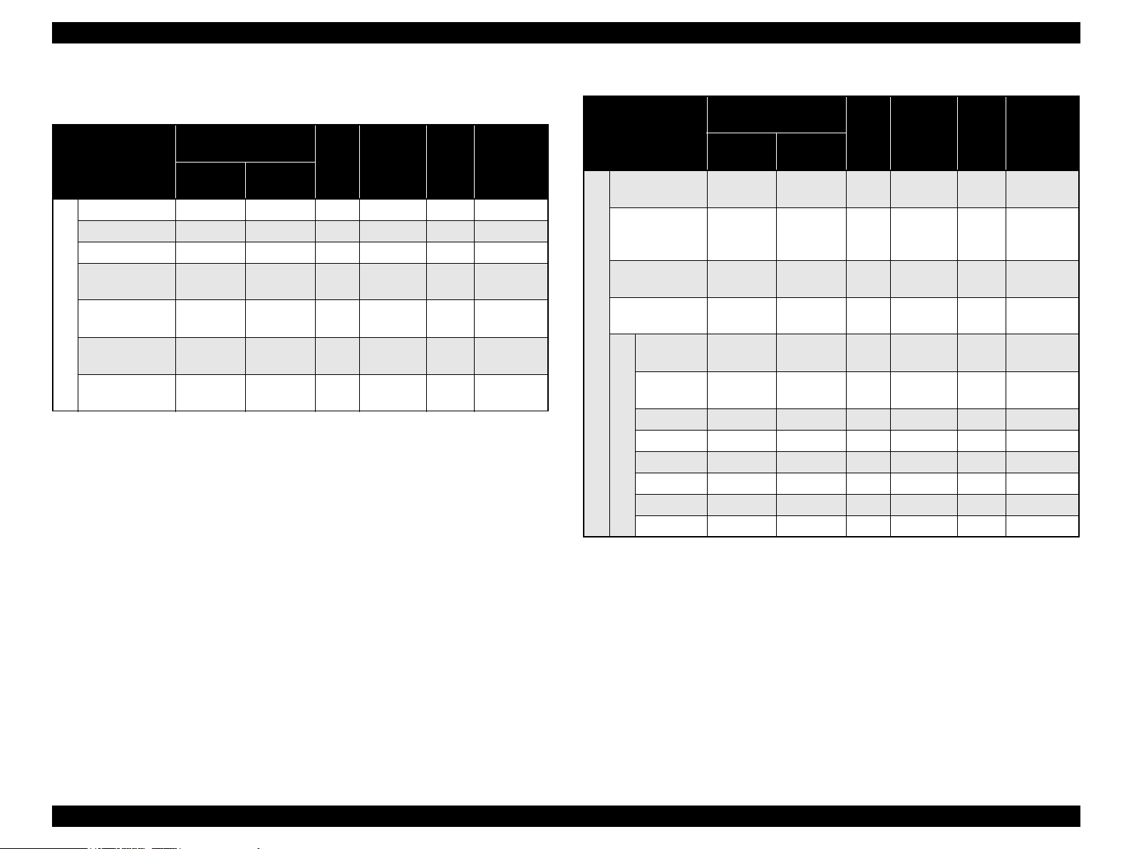
Applicable Paper Sizes, Paper Types, and Paper Orientation
Table 1-7. Applicable Paper Sizes, Paper Types, and Paper Orientation
Paper size Unit mm
Paper Size
Vertical
(length)
(inch)
Horizontal
(width)
A4 297.00 210.00 {{ {SEF
A5 210.00 148.00 { - - SEF
B5 257.00 182.00 { --SEF
Letter 279.40
(11.00)
Half Letter 215.90
Plain paper
(8.50)
EXECUTIVE 266.70
(10.50)
G.Letter 266.70
(10.50)
215.90
(8.50)
139.70
(5.50)
184.15
(7.25)
203.20
(8.00)
MP
tray
Optional*1
cassette
unit
Duplex
print
unit
Paper
Orientation
{ { { SEF
{ --SEF
{ - - SEF
{ --SEF
Table 1-7. Applicable Paper Sizes, Paper Types, and Paper Orientation (continued)
Paper size Unit mm
Paper Size
Japanese official
postcard
*4
Japanese official
returned postcard
*4
148.00 100.00
200.00 148.00
Transparency A4:297.00
LT:279.40
Label A4:297.00
LT:279.40
MONARCH 190.5
(7 1/2)
Com-10 241.30
Special applications
*2
DL 220.00 110.00 { - - SEF
(9 1/2)
Vertical
(length)
(inch)
Horizontal
(width)
A4: 210.00
LT:215.90
A4: 210.00
LT:215.90
98.43
(3 7/8)
104.78
(4 1/8)
C5 229.00 162.00 { --SEF
Envelope
C6 162.00 114.00 { - - SEF
Yokei #0 *5235.00 120.00 { --SEF
Yokei #4 *5235.00 105.00 { - - SEF
Yokei #6 *5190.00 98.00 { --SEF
MP
tray
Optional*1
cassette
unit
Duplex
print
unit
Paper
Orientation
{ - - SEF
{ --SEF
{ - - SEF
{ --SEF
{ - - SEF
{ --SEF
*3
*3
*3
*3
*3
*3
*3
*3
Note *1: The dedicated cassette for A4 only or Letter only (by factory default).
*2: The supported envelope sizes differ depending on destination.
*3: Refer to “Envelope Orientation” (p.28) for details on feeding direction of envelopes.
*4: Curls must be straightened.
*5: JIS envelope.
NOTE 1:
SEF (Short Edge Feed): The short edge of the paper is fed to the printer.
2:
“-”: Not supported.
Product Description Basic Specifications 27
Page 28
EPSON AcuLaser C1900/AcuLaser C900 Revision A
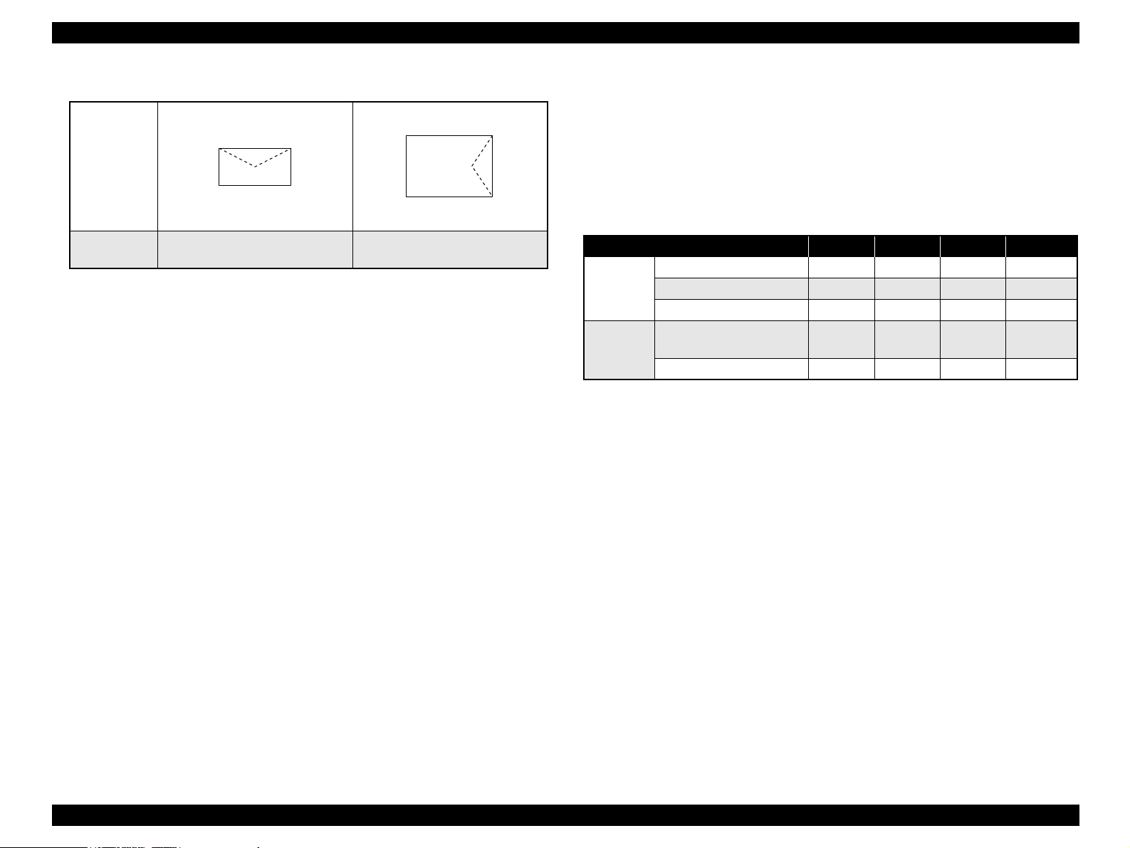
Envelope Orientation
Optional 500-sheet cassette unit
Paper size: Fixed on A4 or Letter
Feeding
direction
→
Paper thickness: 60 g/m
Output Paper Capacity
Face-down (FD) tray only 200 sheets
2
~ 90 g/m
2
Dimensions and Weights
Table 1-8. Outline Dimensions and Weight
Envelope types
Note *: JIS envelope.
NOTE 1:
Envelopes must be loaded facing the printing side up with the flaps heading
MONARCH, DL Com-#10, C6
Yokei #0*, Yokei #4* Yokei #6
*
C5
forward or backward to the paper feed direction.
2:
Opened flaps must be closed.
3:
Printing on the backside (where a flap seal is being sealed) is not possible.
4:
Only envelopes without adhesive or adhesive tapes can be used.
Paper Sizes for Feeding
Regular paper sizes or user defined paper sizes within applicable paper sizes below.
Main unit
Paper width: 92.00 mm ~ 216.00 mm
Paper length: 148.00 mm
Paper thickness: 60 g/m
*1
~ 356.00 mm
2
~ 163 g/m2 (190 g/m2: Japanese official postcard)
Note *1: 148.00 mm ~ 356.00 mm in low-speed <2> mode only and
210.00 mm ~ 356.00 mm in standard mode
Duplex print unit
Paper size: A4, Letter
Paper thickness: 60 g/m
NOTE:
Only regular sizes are supported, while user defined paper size
cannot be used.
2
~ 90 g/m
2
Stand-alone
Options
Installed
Note *1: This value includes the height of the right-side paper path.
*2: This value includes the weight of the consumables, controller circuit board and
Note : Dimensions have a tolerance of ±5mm and weights have a tolerance of ±0.5kg.
Consumables
Developer cartridge (Black, Cyan, Yellow, Magenta)
Photoconductor unit
Transfer belt unit
Waste toner collector
Regular Replacement Parts
Fuser unit
Second transfer roll
Power Supply
Paper source Width Depth Height Weight
Main unit 429 mm 521 mm 406 mm 29 kg
Optional cassette unit 380 mm 485 mm 178 mm 5.3 kg
Duplex print unit 96 mm 340 mm 330 mm 2.0 kg
Main unit+
Optional cassette unit
Main unit + Duplex print unit 473 mm 521 mm 406 mm 31.0 kg
operation panel.
100 V
± 10% : 50Hz
120 V ± 10% : 50Hz
220 ~ 240 V ± 10% : 50Hz
469 mm 521 mm 526 mm 34.3 kg
±3Hz
±3Hz
±3Hz
/ 60 Hz
/ 60 Hz
/ 60 Hz
±3Hz
±3Hz
±3Hz
*2
Product Description Basic Specifications 28
Page 29
EPSON AcuLaser C1900/AcuLaser C900 Revision A
Power supply to the controller
5.0 V
± 5%, 2 A or less
3.3 V
± 5%, 5 A or less
Power Consumption
<AcuLaser C1900>
Table 1-9. Power Consumption (AcuLaser C1900)
100 V 120 V 230 V
Maximum current rated 100 V:13 A or less 11 A or less 7 A or less
Maximum 1100 W 1100 W 1100 W
Average at continuous
printing in B/W
Average at continuous
printing in color
Average during standby
with heating ON
Average during sleep mode
Power Consumption
with heater OFF
Powered off mode 0Wh 0Wh 0Wh
- 372 Wh 352 Wh
- 247 Wh 241 Wh
- 108 Wh 107 Wh
30 W or less 15 W or less 12 W or less
<AcuLaser C900>
Table 1-10. Power Consumption (AcuLaser C900)
100 V 120 V 230 V
Maximum current rated 100 V:13 A or less 11 A or less 7 A or less
Maximum 1100 W 1100 W 1100 W
Average at continuous
printing in B/W
Average at continuous
printing in color
Average during standby
with heating ON
Average during sleep mode
Power Consumption
with heater OFF
Powered off mode 0Wh 0Wh 0Wh
352Wh 351 Wh 352 Wh
253Wh 243 Wh 243 Wh
108Wh 111 Wh 100 Wh
10 W or less 11 W or less 8 W or less
Product Lifetime
Main unit : 200 k pages printed or five years, whichever
comes first
Optional cassette unit : 200 k pages printed or five years, whichever
comes first
Duplex print unit : 200 k pages printed or five years, whichever
comes first
Noise
Table 1-11. Noise
In printing In standby
Main unit Color mode 54 dB(A) or less
B/W mode 54 dB(A) or less
When full-options are installed
Note *: The noise with all options installed is the value actually measured.
*
54 dB(A) or less 39 dB(A) or less
39 dB(A) or less
Exhaust Gas
Ozone concentration : 0.02m g/m
(New Blue Angel standard compliance)
Styrene concentration : 0.07m g/m
(New Blue Angel standard compliance)
Dust concentration : 0.150m g/m
(New Blue Angel standard compliance)
Nitrogen dioxide : 5 ppm or less
Carbon monoxide : 30 ppm or less
3
or less
3
or less
3
or less
Hazardous Materials
None of the Photoconductor (OPC), toners, or plastic contains is hazardous
material.
NOTE: Note: For the standards, refer to “1.2.8 Compatible Standard (p. 36)”.
Current Consumed (Rating)
Table 1-12. Current Consumed
5V 24V
Optional 500-sheet Cassette Unit 0.2A 1A
Duplex Unit 0.1A 0.4A
Product Description Basic Specifications 29
Page 30
EPSON AcuLaser C1900/AcuLaser C900 Revision A
1.2.3 Paper Specifications
Paper that Causes Printing Defects, Paper Jams or Printer
Malfunctions if Used
• Copy papers (carbon papers, non-carbon papers), thermal papers,
impact papers, acid-based papers
• Papers that are too thin or too thick
• Papers that are wet or damp
• Papers with special coatings or paper for color printers with processed
surfaces
• Papers that are too smooth (slick and slippery) or too rough on its
surfaces
• Papers with significantly different roughness on each surface of front
and back side
• Papers with punch holes for binders or perforations
• Creased, curled or torn paper
• Irregularly shaped paper or paper with non-perpendicular corners
• Labels that peel off easily
• Papers with glue, staples or paper clips attached to it
• Special applications for ink jet papers
(super-fine, glossy paper or film, etc.)
• Papers that were previously used in a thermal or ink jet printer
• Transparencies for other color/monochrome laser printers or
photocopiers
• Sheets already printed on other color / monochrome laser printers or
photocopiers
• Sheets of paper stuck together
• 4-page jointed postcard, and Japanese official postcard, nonofficial
postcard, sealed postcard for ink jet printers
• Iron print coated paper (for both inkjet and laser printers)
• Sheets deteriorate or discolor by at 180
°
C or cooler
1.2.3.1 Paper type
Standard Paper
Domestic:
FX P paper (B/W), EPSON high-quality plain paper (A4/LT)
Overseas:
4024 paper (20 lb) (B/W), EPSON high-quality plain paper (A4/LT)
Plain paper
2
60 g/m
Generally applied copy paper, recycled paper
Special Applications
EPSON Dedicated transparency sheet (A4/LT)
EPSON dedicated coated paper (A4)
Japanese official postcard (for domestic models)
Japanese official returned postcard (for domestic models) with no crease
Label
Thick paper (91 g/m
Envelope
NOTE 1:
~ 90 g/m2 (16 lb ~ 24 lb)
2
~ 163 g/m2)
lb: Ream weight = lb / 500 sheets / 17” × 22”
2
g/m
: 1 g/m2 = 0.2659763 lb
2:
When purchasing bulk paper, be sure to check that the paper can be properly
fed beforehand.
C A U T I O N
C H E C K
P O I N T
When “Kamo mail” Japanese official postcards or illustrated
postcards are used, paper feed roller may be soiled with paper
dust, causing difficulties in feeding these postcards properly. In
this case cleaning is required following the “6.1.2 Cleaning”
(p.217).
Product Description Basic Specifications 30
Page 31

EPSON AcuLaser C1900/AcuLaser C900 Revision A
1.2.3.2 Paper Feeding
Table 1-13. Paper Feeding
Special applications
)
2
Paper source
Recommended paper
Standard MP tray {
Optional Optional 500-sheet
cassette unit
Duplex print unit
{ : The paper feed reliability and image quality assured.
∆
: Paper feeding and printing are possible, however only for the use of generally applied types
of paper.
The Image quality is not assured.
{
{
× : Paper feeding is impossible.
Plain paper
∆∆∆∆ ∆ ∆
∆
∆
Transparency
Japanese official
postcard
Label
Thick paper
(91 ~ 163 g/m
Coated paper
× × × × ×
ЧЧЧЧЧ
Envelope
1.2.3.3 Printing Area
Maximum Printable Area: Width 208 mm / length 348 mm
Guaranteed Printing Area: All area of a sheet, which is up to the paper size 216
mm × 297 mm or less, except 4 mm of vertical and
horizontal margins
NOTE:
A Paper that exceeds the paper length 297 mm is not supported
(refer to the diagram below).
Guaranteed
printing area
Figure 1-2. Guaranteed printing area
NOTE: The printing area may differ depending on each printer product
specification (emulation mode).
Product Description Basic Specifications 31
Page 32

EPSON AcuLaser C1900/AcuLaser C900 Revision A
1.2.4 Reliability and Maintainability
1.2.4.1 Reliability
MPBF/MTBF
Main unit: 35,000 pages or more / 3,000 hours or more
NOTE:
Paper Feed Reliability
Paper jam rate 1/2000 sheets or less 1/1000 sheets or less
Miss-feed 1/2000 sheets or less -
Multiple-sheet feed rate
Wrinkled paper 1/1000 sheets or less 1/500 sheets or less
Creased paper at the top edge
(for 1 c or more
Note *1: Standard environment: 15 ~ 25°C, 35 ~ 70%RH
*2: Multiple-sheet feed rate does not include performance at the boundary between the
*3: 1 C indicates 1 mm of crease at a corner.
*1: Monthly operating hours: Over 300 hours (average)
*1
Table 1-14. Paper Feed Reliability
Simplex printing Duplex printing
*2
*3
)
Defines the reliability of humidity-no adjusted paper of the plain paper (A4, Letter).
original paper and the replenished paper that occurs after replenishing paper.
1/500 sheets or less -
1/1000 sheets or less 1/500 sheets or less
*1
Printing Start Position Accuracy
Main scanning
Simplex
printing
Duplex
printing
direction
reference
position (c)
Sub scanning
direction
reference
position (a)
Main scanning
direction
reference
position (c)
Sub scanning
direction
reference
position (a)
±2.0mm
±2.5mm
Printing Area
±3.0mm
±2.5mm
Skew
The table below shows specification values converted to dot-2 pattern reference.
Table 1-15. Skew
A4
Simplex
printing
Duplex
printing
Main scanning direction (|c-d|)
Sub scanning direction (|a-b|)
Main scanning direction (|c-d|)
Sub scanning direction (|a-b|)
2.12 mm
1.56 mm
3.19 mm
2.60 mm
Paper Feed Direction
Metric length
Table 1-16. Skew
A4
Simplex
printing
Duplex
printing
Main scanning direction (|c-d|)
Sub scanning direction (|a-b|)
Main scanning direction (|c-d|)
Sub scanning direction (|a-b|)
195.58 mm
281.61 mm
195.58 mm
281.61 mm
Product Description Basic Specifications 32
Page 33

EPSON AcuLaser C1900/AcuLaser C900 Revision A
Height of Curl of Printed Pages
1.2.5 Operating Conditions (Including Consumables)
Table 1-17. Height of Curl of Printed Pages
Paper type Height of curl
Standard paper, plain paper 30 mm or less
Transparency 15 mm or less
Other special applications Not regulated
NOTE 1:
Same in both simplex printing and duplex printing
2:
Measuring conditions
Non arrayed monochrome printing with 5% of image occupation rate, or
color printing with 5% of image occupation rate for each color (20% in
total). Measured after 1 p/J of intermittent printing for 10 sheets and leaving
unattended for one minute.
Image occupation rate and alignment pattern differ depending on printing
condition.
1.2.4.2 Durability
Printing Volume
Average 3,000 pages / per month
Maximum 35,000 pages / per month
NOTE: The standard mode provides print ratio between color <2P/J> and
monochrome <3P/J> as color: monochrome = 1: 3
Air Temperature and Humidity
Table 1-18.
Temperature (°C) Humidity (%RH) Others
Printer is in operation 10 ~ 35 15 ~ 85 With no condensation
Printer is stopped
0 ~ 35 10 ~ 85
Unattended time:
72 hours or less
Air Pressure (Altitude)
741 hPa or more (2,500 m or less)
Level
1° difference or less in front and back, or left and right.
Lighting
3,000 lx or less (no exposure to direct sunlight)
1.2.4.3 Maintenance
MTTR Within 30 minutes in average.
(Time required for service personnel to determine and correct the cause of the
malfunction)
Product Description Basic Specifications 33
Page 34

EPSON AcuLaser C1900/AcuLaser C900 Revision A
Space Requirements
In order to ensure that the printer operates properly, provide at least as sufficient
space as shown in the figure below.
NOTE: The space height required above the top cover is 200 mm or more.
1225 mm
426 mm
200 mm
406 mm
Figure 1-3. Required Surrounding Space (Front View)
300 mm
500 mm
521 mm
1372 mm
700 mm 150 mm
Figure 1-4. Required Surrounding Space (Top View)
Product Description Basic Specifications 34
Page 35

EPSON AcuLaser C1900/AcuLaser C900 Revision A
1.2.6 Storage and Transport Environments of the Packaged Printer Main Unit and Optional Products
NOTE: Including Bundled Consumables
Temperature and Humidity Conditions
Table 1-19.
Temperature Humidity Warranty period
*2
Normal Conditions 0 to 35 °C 30 to 85% RH
Severe Conditions High temperature:
35 ~ 40 °C *1
Low temperature:
-20 ~ 0 °C
Note *1: 35 ~ 55 °C when the DEVELOPER cartridges and photoconductor unit are
uninstalled.
*2: Condensation must be avoided.
High humidity:
85 ~ 95% RH *2
Low humidity:
10 ~ 30% RH
Barometric Pressure for Storage (Altitude):741 ~ 1013 hPa
NOTE:
1 613 ~ 1013 hPa when the DEVELOPER cartridges and
photoconductor unit are uninstalled.
Dropping : No damage must occur for packaged products in dropping from
52 cm height, and in 1 corner, 3 edges, 6 sides of direction.
Compliant with the EPSON transport assessment standard (TAE05-001-001).
18 month after production
1/30 of 18 months
*2
1.2.7 Electrical Feature
In the following items, all options are excluded.
Fast Transient / Burst (AC Line Noise)
The following conditions shall be met in the “IEC61000-4-4” compliant evaluation.
1kV : No error excepting minor dot errors.
1.8kV : No Component damaged.
Instantaneous Outages
DIP 100% of instantaneous outages (at rated voltage - 10%) for 1-cycle
No deterioration in the printing quality.
The following condition shall be met in the “IEC61000-4-11” compliant
evaluation.
• 95% lowered 0.5 cycle : No error excepting minor dot errors.
• 30% lowered 25 cycle : No component damaged.
• 95% lowered 250 cycle : No component damaged.
Resistance to Static Electricity
The following condition shall be met in the “IEC61000-4-2” compliant evaluation.
Contact discharge 8 kV : No error in any devices.
Discharge into the air 15 kV : No error in any devices.
Inrush Current
Vibration : Must conform to the JIS Z0200-1999 level 1
Compression : Refer to Packing Specifications.
Size : Refer to Packing Specifications.
Weight : Refer to Packing Specifications.
Loading : Refer to Packing Specifications.
Pallet Size : Refer to Packing Specifications.
1/2-cycle : 50 A or less (0-peak) (At 23
<Reference: Actually measured value including heater inrush>
• 100V: 1/2 cycle 88.0 A (0-peak)
• 120V: 1/2 cycle 66.0 A (0-peak)
• 220V: 1/2 cycle 35.6 A (0-peak)
• 240V: 1/2 cycle 38.0 A (0-peak)
(
By cold start at 23°C
)
°
C or higher)
Insulation Resistance
10 MΩ or more
Product Description Basic Specifications 35
Page 36

EPSON AcuLaser C1900/AcuLaser C900 Revision A
Withstand Voltage
Breakdown must not occur when the voltages shown in the table below are applied for
1.2.8 Compatible Standard
Safety Standard
one minute.
100 V/120 V UL1950 3rd Edition
For 100/120 V system models AC1,000 V
For 220 V system models AC1,500 V
Leak Current
100 V: 0.25 mA or less
120 V: 3.5 mA or less
Table 1-20. Withstand Voltage
Across primary and chassis
*1
200 V system IEC60950 2nd + Amd 1, 2, 3, 4
Safety Standard (Laser Transmission)
120 V FDA21CFR Chapter 1 Subchapter J Part1040
200 V system EN60825-1 + A11
CSA C22.2 No.950-95 3rd
EN60950: 2nd + Amd 1, 2, 3, 4, 11 (1997)
Annex ZB, ZC
220 V: 3.5 mA or less
<Reference>
NOTE: *1: The measuring method is compliant with “PC-11-1988”.
• Laser diode
Wavelength (Min. ~ Max.:)) 770 ~ 795 nm
Max. output rating: 5 mW
EMI
100 V VCCI Class B J55022 Class B
120 V FCC 47CFR Part 15 Subpart B, Class B
CNS13483 Class B
ICES-003 Issue 3 Class B (C108.8-M1983)
200 V system EN 55022 Class B
CISPR Publication22 Class B
Electrical higher harmonics wave
Complies with the Higher Harmonics Restraint Guidelines
100 V: Compliant with JBMG-3 (1995)
200 V: Compliant with EN61000-3-2 Class A
Electrical Power Consumption
Conforms to the International Energy Star Program standards
Product Description Basic Specifications 36
Page 37

EPSON AcuLaser C1900/AcuLaser C900 Revision A
Others
Toner : No materials hazardous to human health
(conforms to OSHA, TSCA, and EINECS)
OPC : No materials hazardous to human health
(conforms to OSHA)
Ozone generation : Compliance with UL 478, the 5th edition
Materials : Compliance with the Swiss Environmental Protection
Standards (contains no CdS)
1.2.9 Consumable / Regular Replacement Component Specifications
1.2.9.1 Specifications
Consumables
Table 1-21. Consumable Specifications
Name Component
Developer cartridge
(Black, Magenta, Cyan,
Yellow
Photoconductor unit
Transfer unit Transfer belt unit, etc. 210 K images
Waste toner collector Waste toner collector 25 K images
Developer,
toner hopper
Photoconductor unit
method
Lifetime
specifications
4.5 K images or
*1
more
1.5 K images or
*1
more
45 K images
*1
*2
*2
*3
External
dimension
80 (W)
300 (D)
60 (H)
101 (W)
365 (D)
65 (H)
252 (W)
373 (D)
133 (H)
284 (W)
48 (D)
288 (H)
Weight
0.7 kg 150 g
0.6 kg 63 kg
0.56 kg -
3.0 kg -
0.2 kg -
Initial
toner
filling
Note *1: Average number of printed pages in printing with 5% of image occupation rate (A4).
The lifetime differs according to paper sizes and printing methods (such as toner
save processing).
*2: The lifetime differs by number of times of powering on and off, and media used. The
lifetime is shortened in printing on special applications such as thick paper, postcard,
envelope, transparency.
*3: Average number of printed pages in printing with 5% of image occupation rate (A4).
The lifetime differs according to printing occupation rate
*4: See “1.2.9.3 Lives of Components (p.39) ”.
Product Description Basic Specifications 37
Page 38

EPSON AcuLaser C1900/AcuLaser C900 Revision A
Regular Replacement Parts
Table 1-22. Regular Replacement Parts
Name Lifetime specifications
Fuser Unit 120 K pages
Second transfer roll 120 K pages
Note *1: See “1.2.9.3 Lives of Components (p.39)”
*1
1.2.9.2 Storage and Transport Environments for Packages
Temperature and Humidity Conditions
Table 1-23.
Temperature Humidity
Normal conditions 0 ~ 35 °C 30 ~ 85%RH
Severe conditions
Note *1: Condensation must be avoided
*2: Storage period after unsealing is up to 12 months under operating environments.
Condensation must be avoided
High temperature:35 ~ 40 °C
Low temperature:-20 ~ 0 °C
High humidity:85 ~ 95%RH *1
Low humidity:10 ~ 30%RH *1
*1
Warranty
Period
18 month
(unopened)
1/30 of 18
month
Barometric Pressure in Storage (Altitude)
740 ~ 1013 hPa
Dropping for Packages
No damage in JIS Z0200-1999 Level 1.
Vibration for Packages
No damage in the following conditions.
*2
Frequency : 5 ~ 100 Hz (5 minutes)
Acceleration : 7.35 m/s
2
(0.75 G)
Excitation direction : X, Y, Z directions
Excitation time : 60 minutes for each direction of X, Y, Z
(180 minutes in total)
Packaging Specifications
Refer to the packing specifications.
Product Description Basic Specifications 38
Page 39

EPSON AcuLaser C1900/AcuLaser C900 Revision A
1.2.9.3 Lives of Components
B/W mode
Table 1-24. Lives of Components (B/W mode)
Component Specification Speed Mode
Developer
Cartridge
Photoconductor
Unit
Transfer Belt
Unit
Waste Toner
Collector
Fuser Unit 120k pages Standard 120k 120k
Second
Transfer roll
4.5k images
*1
<Black>
1.5k images
*2
<Black>
45k images Standard 45k 24k 10k
210k images Standard 210k 70k
25k images Standard 25k 25k 21.6k
120k pages Standard 120k 120k 120k
Continuous
Printing
(Unit: Pages)
4P/J
(Unit:
Pages)
1P/J
(Unit:
Pages)
Standard 4.5k 4.5k 4.5k
Low-speed <2> 4.5k 3.2k
Low-speed <3> 4.5k 4.5k 3.2k
Standard 1.5k 1.5k
Low-speed <2> 1.5k 1.5k 1.0k
Low-speed <3> 1.5k 1.0k
Low-speed <2> 15k 5k
Low-speed <3> 15k 10k 5k
Low-speed <2> 70k 60k 42k
Low-speed <3> 70k 42k
Low-speed <2> 25k 14.4k
Low-speed <3> 25k 23.3k 14.4k
Low-speed <2> 120k 120k 120k
Low-speed <3> 120k 120k
Low-speed <2> 120k 120k
Low-speed <3> 120k 120k 120k
Color mode
Table 1-25. Lives of Components (Color mode)
Component Specification Speed Mode
Developer
Cartridge
Photoconductor
Unit
Transfer Belt
Unit
Waste Toner
Collector
Fuser Unit 120k pages Standard 120k 120k 120k
Second Transfer
roll
4.5k images
<Y,M,C>
Continuous
Printing
(Unit: Pages)
*1
Standard 4.5k 4.5k 4.5k
Low-speed <2> 4.5k 4.5k 4.5k
4P/J
(Unit:
Pages)
1P/J
(Unit:
Pages)
Low-speed <3> 4.5k 4.5k 4.5k
4.5k images
<Black>
*1
Standard 4.5k 4.5k 4.5k
Low-speed <2> 4.5k 4.5k 3.5k
Low-speed <3> 4.5k 4.5k 3.5k
1.5k images
<Y,M,C>
*1
Standard 1.5k 1.5k 1.5k
Low-speed <2> 1.5k 1.5k 1.5k
Low-speed <3> 1.5k 1.5k 1.5k
1.5k images
<Black>
*1
Standard 1.5k 1.5k 1.5k
Low-speed <2> 1.5k 1.5k 1.1k
Low-speed <3> 1.5k 1.5k 1.1k
45k images Standard 11.25k 10k 7.5k
Low-speed <2> 7.5k 6.2k 4.1k
Low-speed <3> 7.5k 6.2k 4.1k
210k images Standard 52.5k 46.7k 35k
Low-speed <2> 35k 32.3k 26.5k
Low-speed <3> 35k 32.3k 26.5k
25k images Standard 6.25k 6.25k 6.25k
Low-speed <2> 6.25k 6.25k 6.25k
Low-speed <3> 6.25k 6.25k 6.25k
Low-speed <2> 120k 120k 120k
Low-speed <3> 120k 120k 120k
120k pages Standard 120k 120k 120k
Low-speed <2> 120k 120k 120k
Low-speed <3> 120k 120k 120k
Product Description Basic Specifications 39
Page 40

EPSON AcuLaser C1900/AcuLaser C900 Revision A
NOTE 1: Operation currently taken into consideration as conditions for life determination
•AIDC
•ATVC
• Preliminary operation at the time of consumables exchange. (T/C, D/C)
2: Operation currently witch not taken into consideration as conditions for life
determination.
• Power ON/OFF
• Jam processing
3: Paper kind
• Low-speed<2>: Thick paper / Coated paper
• Low-speed<3>: Transparency
Note *1: 4.5k cartridge: Up to 6000 pages (A4size) / print ratio less than 5%.
*2: 1.5k cartridge: Up to 2000 pages (A4size) / print ratio less than 5%.
Product Description Basic Specifications 40
Page 41

EPSON AcuLaser C1900/AcuLaser C900 Revision A
1.3 Controller Unit Specifications
1.3.1 Controller Basic Specifications
<AcuLaser C1900>
CPU : SPC603ei 300Mhz
Enhanced technology : AcuLaser Color Halftoning,
CRIT/RIT(VIPS + CDMC)
ROM : 4MB Flash (program) + 4MB MASK (fonts)
RAM : Standard 32MB
1 GB maximum (Standard 32 MB RAM DIMM must
be replaced) For RAM expansion, use 168-pin
SDRAM DIMM compatible with PC100 or PC133
available commercially.
NVRAM : 128Kbit (16KB)
Expansion slot : RAM DIMM 2 slots
(1 slot already used up by Standard RAM)
ROM DIMM 1 slot (for optional PS)
Control Panel : 20 digits × 1 LCD, 6 buttons and 3 LEDs
Interface : 10/100baseTx Ethernet
USB 1.1(2.0 FS 12Mbps Certified)
IEEE1284 parallel (ECP, Nibble, Compatibility),
B Type connector
Type-B 1 slot (Level 3 supported)
<AcuLaser C900>
CPU : VR4305-48MHz
Enhanced technology : CPGI (supporting monochrome) installed
CRIT, RIT
RAM : Standard:16MB, Maximum:144MB
DIMM Options : SDRAM DIMM dedicated to AcuLaser C1000/
AcuLaser C7000 (the shape of slot is different from PC
slots)
16 MB, 32 MB, 64 MB and 128 MB
Program ROM : 2MB (32bit width)
EEPROM : 256 byte
Control Panel : 2 LEDs
Interface
Standard
• Parallel : 1ch, IEEE1284 compatible bi-directional,
B-Type connector, Compatibility, Nibble, ECP
• USB1.1 : 1ch
Options : Type-B 1 slot (compatible with Level-2)
However, currently only Leo2.1 is supported.
Printer Mode : ESC/PageS Printing System
HDD : Installable as an option, which is common with
AcuLaser C8600
Printer Mode : ESC/Page Color mode, ESC/Page(B/W) mode
LJ4, GL/2, ESC/P2, FX, I239X
EJL, PJL, RCC, DIAG mode
Adobe PostScript 3 (Optional)
Installation Format : Fixed to the printer body
Product Description Controller Unit Specifications 41
Page 42

EPSON AcuLaser C1900/AcuLaser C900 Revision A
1.3.2 Differences in Jumper Settings between Designated Markets
For AcuLaser C1900 / AcuLaser C900, the following settings are made according to
the designated market. Settings are determined at the factory because of use of jumper
resistance.
<AcuLaser C1900>
Table 1-26. Jumper Setting
Jumper
JP501 1-2 SSCG Spread Setting
JP502 2-3
Pattern Jumper
DIC Jumper
JP503 1-2
JP504 1-2
JP505 2-3
JP403 Short Paper Unit System Designation (mm/inch)
JP404 Open Default Paper Setting (A4/Letter)
JP701 Open
JP702 Open
<AcuLaser C900>
Jumper
Pattern Jumper (INPT1)
: at WS, ES
DIC Jumper Switch
(INPT1): at production
Pattern Jumper (INPT0) R190
DIC Jumper Switch
(INPT2)
R191
JP103
JP102
Table 1-27. Jumper Setting
Open 1
Open 1 Default Setting for MP Tray Paper Size: A4
Short 0 Default Setting for MP Tray Paper Size: LT
Open 1 Parallel Interface Receive Mode: Nibble
Short 0 Parallel Interface Receive Mode: ECP
SSCG Setting (Clock rate)
SSCG Setting (Diffuse value designation)
Network Auto Negotiation Setting
1.3.3 External I/F Specifications
<AcuLaser C1900>
AcuLaser C1900 has the following host interfaces as standards:
IEEE1284 parallel interface
USB 1.1 (2.0 FS 12Mbps Certified)
10/100baseTx Ethernet
Option: Type-B interface (Level 3 supported)
Ethernet I/F
Type B I/F
Main Unit Side
Figure 1-5. Position of host interface
Parallel I/F
USB I/F
Product Description Controller Unit Specifications 42
Page 43

EPSON AcuLaser C1900/AcuLaser C900 Revision A
<AcuLaser C900>
AcuLaser C900 has the following host interfaces as standards:
IEEE1284 parallel interface
USB interface
Optional Type-B I/F 1slot -(Option)
NOTE: Switching between host interfaces is automatic only. Each interface
cannot be switched on and off individually.
Optional I/F
Parallel I/F
(IEEE1284 B-type)
USB I/F
Figure 1-6. Position of host interface
1.3.3.1 Parallel Interface Specifications
<AcuLaser C1900>
Interface Type
IEEE 1284 bi-directional high speed parallel interface
Operating Modes
Compatibility, Nibble, ECP
Connector Model Names
57RE-40360-830B(D7A) DDK or equivalent products
Conforming Plugs
Amphenol or equivalents
The initial value for this printer Device ID is as shown below.
In the following description, in order to make it easier to read, carriage returns have
been added, but actually, the character string is continuous without carriage return
codes being included. The CMD items are not in the same order. MODE and STATUS
items are not included. In the contents of DES items, MFG and MDL are connected by
a space.
*1
**
;
MFG:EPSON;
CMD:PJL,EJL,ESCPL2,ESCP9,PRPXL24-01,PCL,HPGL2-01,ESCPAGE04,ESCPAGECOLOR-01**
MDL:**
*3
;
CLS:PRINTER;
DES:**
*4
;
*2
;
Product Description Controller Unit Specifications 43
Page 44

EPSON AcuLaser C1900/AcuLaser C900 Revision A
MFG, MDL, DES and CID of Device ID are re-definable. (This must not be included
in the manual.) And the CID field does not respond with the default value, but responds
with the defined character string only when redefined.
Device ID when redefined is as follows. “xxxxx” is the user-defined character string.
MFG:*****;
CMD: PJL,EJL,ESCPL2,ESCP9,PRPXL24-01,PCL,HPGL2-01,ESCPAGE04,ESCPAGECOLOR-01**
*2
;
MDL:*****;
CLS:PRINTER;
DES:*****;
CID:*****;
Note *1: Contains a hexadecimal value od Device ID's “total number of characters+2”
*2: “POSTSCRIPT” is added only when the PostScript3 module is installed
*3: Indicates the model name AcuLaser C1900
*4: Indicates the maker and model name EPSON AcuLaser C1900
<AcuLaser C900>
The default device ID setting for AcuLaser C900 is as follows:
MFG:EPSON;CMD:ESCPAGES-02;MDL: AL-C900;CLS:PRINTER;
DES:EPSON AL-C900;
Switching between communication modes is achieved by changing the jumper setting
(JP102/jumper switch INPT2) on the controller board.
Table 1-28. Communication Mode by JP102 Setting
JP102 Setting Communication Mode Explanation
The ECP communication mode is not supported,
Open Nibble
Short ECP
and the Reverse mode is only available in the
Nibble communication mode.
The ECP communication is supported (ECP is
the default setting)
1.3.3.2 USB Interface Specifications
Universal Serial Bus Specification Rev.2.0 FS is supported, at 12 Mbps.
AcuLaser C1900/AcuLaser C900 has an 18-digit serial ID. The ID is printed on the
bottom of the Status sheet. Each of the 18 digits denotes the following information.
1, 2: A number of 00 to 99. Acquired for each model.
“16” for AcuLaser C1900. “17” for AcuLaser C900.
3: “P” for page printer
4, 5: PC number on the assembly belt
6, 7: Year of assembly
8, 9: Month of assembly
10, 11: Day of assembly
12, 13: Hour of assembly
14, 15: Minute of assembly
16, 17: Second of assembly
18: Reserved digit (0 is normally specified)
The specified USB serial numbers are confirmed in the Status Sheet. The numbers are
displayed on the bottom left of the Status Sheet, next to the ROM version.
C A U T I O N
If the Main Board is replaced for repair, the USB serial number
must be changed to another USB ID. Consequently, a computer
connected to the repaired printer recognizes the printer as a
different one, requiring the printer to reinstall a USB port driver.
Refer to USB ID Input (p.209)
.
NOTE: For details on the jumper setting, refer to “1.3.2 Differences in Jumper
Settings between Designated Markets” (p.42).
Product Description Controller Unit Specifications 44
Page 45

EPSON AcuLaser C1900/AcuLaser C900 Revision A
1.3.3.3 Ethernet Interface Specifications (AcuLaser C1900)
Interface Types:
10Base T, 100Base TX, Half Duplex, Full Duplex: auto switching when the power
is turned On.
Printing Protocols
TCP/IP
LPR, FTP, IPP, PORT2501, PORT9100
Microsoft Network
SMB
Netware
Operating mode
Standby (factory default), NDS Print Server, Bindery Print Server, Remote
Printer
AppleTalk
Control Protocols
TCP/IP
SNMP, ENPC, HTTP, TELNET, DHCP, BOOTP, PING
Microsoft Network
Auto-IP, SSDP
NetBEUI
SNMP, ENPC
Connector Name : RJ45
Compatible Cable : 2-pair STP (10BaseT, 100BaseTX)
In order to conform to FCC Class B, EN55022 Class B and VCCI Class B, a shielded
type cable shall be used.
Table 1-29. Pin Arrangement
Pin Signal Name I/O Pin Signal Name I/O
1 Tx+ O 5 N.C. –
2 Tx– O 6 Rx– I
3 Rx+ I 7 N.C. –
4 N.C. – 8 N.C. –
Entity Type : Refer to “1.3.3.4 Type B Interface Specifications” (p.46).
Netware
SNMP, ENPC
AppleTalk
SNMP, ENPC
NOTE: ENPC:EPSON Network Peripheral Control Protocol
IPP: Internet Printing Protocol
Product Description Controller Unit Specifications 45
Page 46

EPSON AcuLaser C1900/AcuLaser C900 Revision A
1.3.3.4 Type B Interface Specifications
AcuLaser C1900/AcuLaser C900 has one Type B optional interface slot as standards.
<AcuLaser C1900>
Main System Type:
MTP600dpi,PW5100dt600dpi,PRG(*****)rev,AP800ma,
SPD0fast,D4
NOTE:
Printer Name : The factory default setting is the same as Product Name.
Product Name : AcuLaserC1900
Emulation Type : See Table 1-30
Entity Type : See Table 1-30
Emulation Emulation Type Entity Type
*1
PS
ESC/Page Color ESCPAGECOLOR-01 EPSONPAGECOLOR1
ESC/Page ESCPAGE-04 -
LJ4 PCL5E-00 EPSONPCL5
I239X PRPXL24-01 EPSONPRPXL24
GL2 HPGL2-01 EPSONHPGL2
FX ESCP9 EPSONFX
ESCP2 ESCPL2 EPSONLQ2
***** ROM version.
Table 1-30. Emulation Type and Entity Type
POSTSCRIPT-00
*1
LaserWriter
*1
Entity Type
<If Emulation is set to AUTO>
• Refer to the above list.
<If Emulation is Fixed>
• The Default Emulation Type and EPSONPAGECOLOR1 are returned.
<AcuLaser C900>
Only Leo2.1 can be used for the Type-B optional interface of AcuLaser C900
Main System Type:
MTP600dpi,PW5100dt600dpi,PRG(*****)rev, AP800ma,
SPD0fast,GDI
NOTE:
***** ROM version.
Printer Name : AL-C900
Product Name : AL-C900
Emulation Type : ESCPAGES-02
Entity Type : EPSONPAGES2
Note *1: Added when the PostScript 3 module is installed.
Emulation Type
<If Emulation is set to AUTO>
• When PS is not started : AUTO (Emulation Types 1, 2, 3...)
• When PS is started : EJL
(POSTSCRIPT-00, other Emulation Types 1, 2, 3...)
<If Emulation is Fixed>
• EJL (Default Emulation Type, other Emulation Types 1, 2, 3,...)
Product Description Controller Unit Specifications 46
Page 47

EPSON AcuLaser C1900/AcuLaser C900 Revision A
1.4 Control Panel
1.4.1 External Appearance and Names of Parts
<AcuLaser C1900>
j
c
f
d e h
g
Figure 1-7. Control Panel of AcuLaser C1900
k
l
i
Table 1-31. Control Panel Description of AcuLaser C1900
No. Name Note
LCD Panel 1 line x 20 characters
c
Ready LED Color: Green
d
Data LED Color: Yellow
e
Error LED Color: Red
f
Start/Stop Button
g
Cancel Job Button
h
Enter Button 3 for password input *
i
Back Button 1 for password input *
j
Up Button 2 for password input *
k
Down Button 4 for password input *
l
Note *1: The key assignment of passwords in indicated (embedded) on the case.
1
1
1
1
Product Description Control Panel 47
Page 48

EPSON AcuLaser C1900/AcuLaser C900 Revision A
<AcuLaser C900>
Table 1-32. Control Panel Description of AcuLaser C900
No. Name Note
Ready LED Color: Green
c
Error LED Color: Red
d
d
c
Figure 1-8. Control Panel of AcuLaser C900
Meaning of LED Flashing
Table 1-33. Meaning of LED Flashing on AcuLaser C900
Ready LED Error LED Supplement Meaning
Off Off - Power off
Controller fatal errors
Off On -
Blink 1 Off -
Blink 3 Off - Warning of consumables (4 types)
Blink 1 Blink 1
Blink 1 Blink 1
Blink 1
and Off
Blink 1 On - Protocol error
On Off -
On Blink 1 -
On On -
Blink 1
Blink alternately Engine error
Blink simultaneously RAM check error, no installed RAM
Repeat this state two
times
• Video error
• Data expansion error
• EEPROM access error
• Software error
Warming up, and Data receiving, Reset, Calibrating
Printer, Cooling Down, Please Wait
Other IPL error
Ready to print, Printing Job, Standby, Warning (other
than consumables)
Recoverable errors
• Check Media Type
• Install consumables (3 types)
• Clean Sensor
• Replace Consumables (4 types)
•Paper Set
• Invalid Size
• Underrun Error
• Mem Overflow
• Duplex Mem Overflow
• Invalid AUX I/F Card
Paper Out, Paper Jam, Duplex Paper Size Error,
Cover Open (2 types)
NOTE 1: After the power on, two LEDs will light up and then go out about 1.5 seconds later.
2: During RAMCHECK, the Ready LED blinks faster than Blink 1
(On for 0.1 sec. and then off for 0.1 sec.)
3: Three types of blink are available:
Blink 1 is a fast blink that goes on and then off for 0.3 second each
Blink 2 goes on and then off for 0.6 second each
Blink 3 is a slow blink that goes on for 0.6 second and then off for 2.4 seconds.
Product Description Control Panel 48
Page 49

EPSON AcuLaser C1900/AcuLaser C900 Revision A
1.4.2 List of Panel Settings (Only with AcuLaser C1900)
This printer's setting item list is shown below.
Values shown in bold and underlined characters are the factory default setting values.
Table 1-34. Function Setting (1)
Menu Item Value
Information Menu Status Sheet
*1
*2
*3
*4, *5
*6
*6
*7
*8
E****F, E***F, E**F, E*F,
EF
*8
E****F, E***F, E**F, E*F,
EF
*8
E****F, E***F, E**F, E*F,
EF
*8
E****F, E***F, E**F, E*F,
EF
*8
E****F, E***F, E**F, E*F,
EF
*8
*8
*8
0 ~ 99999999
0 ~ 99999999
0 ~ 99999999
Status Menu
Reserve Job List
Form Overlay List
Network Status Sheet
AUX Status Sheet
PS3 Status Sheet
PS3 Font List
ESC/Page Font Sample
LJ4 Font Sample
ESCP2 Font Sample
FX Font Sample
I239X Font Sample
C Toner
M Toner
Y Toner
K Toner
Photocondctr
Total Pages
Color Pages
B/W Pages
*9
Table 1-34. Function Setting (1) (continued)
Menu Item Value
Tray Menu MP Tray Size A4
*10
, A5, B5, LT
C10, DL, C5, C6, IB5
LC Size
*11, *12
A4, LT
MP Type Plain, Letterhead, Recycled, Color, Trnsprncy,
Labels
LC Type Plain
, Recycled, Color
Note *1: Displayed only when a Job is registered in Quick Print Job
*2: Displayed and can be executed only when Form Overlay is implemented
*3: Displayed only when the printer starts with Network menu → Network I/F = On
*4: Displayed only when Type-B level 3 is installed
*5: Displayed only when the printer starts with AUX menu → AUX I/F = On
*6: Displayed only when the optional PostScript3 module is installed
*7: Not displayed on the panel, but can be executed from EJL
*8: Can only be viewed but not modified
*9: Displayed only when warning is occurred. All warnings occurred when entering
SelecType Mode can be confirmed in this menu.
*10: A4 or LT, depending on the default paper size of the controller configuration when
shipped from the factory.
*11: Displayed only when the optional Cassette Unit is installed
*12: Set the paper size of Paper Cassette Unit to use. The factory default is not depend on
the controller configuration and always set to A4.
*13: Can be automatically set to Envelope by the engine if MP Tray Size is set to
Envelope (MON, C10, DL, C5, C6, IB5). The print speed for Envelope is
approximately 2 ppm. Letter Head, Transparency, and Label cannot be used in the
LC.
*10
, HLT, GLT, EXE, MON,
Product Description Control Panel 49
Page 50

EPSON AcuLaser C1900/AcuLaser C900 Revision A
Table 1-35. Function Setting (2)
Menu Item Value
Emulation Menu Parallel Auto
USB Auto, LJ4, ESCP2, FX, I239X, PS3*1, GL2
Network Auto
*2
AUX
Printing Menu Page Size A4
Wide A4 Off, On
Orientation Port
Resolution 600, 300
RITech On
Toner Save Off, On
Image Optimum Auto
Top Offset -99.0 ~ 0.0 ~ 99.0 mm step 0.5 mm
LeftOffset -99.0 ~ 0.0
T Offset B
L Offset B
*4
*4
Setup Menu Lang English
Lang Francais
Sprache Deutsch
LINGUA ITALIANO
LENG ESPANOL
SPRAK SVENSKA
Sprog Dansk
Taal Nederl.
KIELI SUOMI
Ling. Portugues
Time Out 0, 5 ~ 60 ~ 300 step 1
Paper Source Auto
MP Mode Normal, Last
Manual Feed Off
, LJ4, ESCP2, FX, I239X, PS3*1, GL2
, LJ4, ESCP2, FX, I239X, PS3*1, GL2
Auto, LJ4, ESCP2, FX, I239X, PS3*1, GL2
*3
, A5, B5, LT*3, HLT, GLT, EXE, MON,
C10, DL, C5, C6, IB5, CTM
, Land
, Off
, Off, On
~ 99.0 mm step 0.5 mm
-99.0 ~ 0.0 ~ 99.0 mm step 0.5 mm
-99.0 ~ 0.0 ~ 99.0 mm step 0.5 mm
, MP, LC
, On
Table 1-35. Function Setting (2) (continued)
Menu Item Value
Setup Menu Copies 1 - 999
Quantity
Duplex
Binding
Start Page
*5
Paper Type Normal
Page Side
Skip Blank Page
*7
*8
*8
*8
*11
*9
Auto Eject Page Off, On
Size Ignore Off
Auto Cont Off, On
Page Protect Auto
Toner Out
*9
LCD Contrast 0 - 7
Panel Lock
*10
Note *1: Displayed only when the optional PostScript3 module is installed
*2: Displayed only when a Type-B interface card is installed
*3: Depending on the default paper size of the controller configuration when shipped
from the factory
*4: Displayed only when the optional Duplex Print Unit is installed
*5: For CTM (user defined) paper size (width x height), the minimum is 92 x 148 mm
and the maximum is 216 x 297 mm.
*6: Displayed only when the optional Cassette Unit is installed
*7: Not displayed on the panel, and not included in the Status sheet either. Possible to be
set at EJL or PJL. Not stored in NVRAM.
*8: Displayed only when the optional Duplex Print Unit is installed
*9: Valid in the ESC/Page, PCL5e, ESCP2, FX, and I239X modes
*10: Not displayed on the panel, and not included in the Status sheet either. Possible to be
*6
set at JL.
*11: Set “Back” when print on the backside of the manual duplex printing.
*12: Even if the toner out occurs, Replace Toner xxxx error will not occur when “Toner
Out = Continue”. As a result, the continuous printing is possible but in this case, the
print quality is not guaranteed. Note when this setting is used with Continue.
1 - 999
Off, On
Long Edge, Short Edge
Front, Back
, Thick, Envelope, Trnsprnc, Coated
Front, Back
Off, On
, On
, On
Stop, Continue
- 15
Off, On
Product Description Control Panel 50
Page 51

EPSON AcuLaser C1900/AcuLaser C900 Revision A
Table 1-36. Function Setting (3)
Menu Item Value
*1
Quick Print Job Menu
ConfidentialJob Menu*5User xxxxxxxxxxxxxx
Reset Menu Clear Warning
Parallel Menu
USB Menu
*11
*11
User xxxxxxxxxxxxxx
*2
Job
*3
Copies
*3,*4
Delete
Enter Password
*7
Job
*8
Copies
*8, *9
Delete
*6
xxxxxxxxxxxxxxx
1 ~ 999
XXXX
xxxxxxxxxxxxxxx
1 ~ 999
Clear All Warnings
Reset
Reset All
SelecType Init
Change Toner C
Change Toner M
Change Toner Y
Change Toner K
*10
*10
*10
*10
Parallel I/F On, Off
Speed Fast, Normal
Bi-D Nibble, ECP
, Off
Buffer Size Normal, Maximum, Minimum
USB I/F On, Off
Buffer Size Normal, Maximum, Minimum
Note *1: Not displayed when nothing is registered in Verify Job, Re-print Job, and Stored Job
*2: Displayed only when Quick Print Job menu → User=<User name> is selected
*3: Displayed only when Quick Print Job menu → Job=<Job name>is selected. After its
execution, the control returns after exiting the SelecType mode.
*4: By executing “Delete” the menu changes to “Job”. “User” is displayed when no job
is registered. When there is no “User”, quit the SelecType menu.
*5: Not displayed when nothing is registered in Confidential Job.
*6: Displayed only when ConfidentialJob menu → User=<User name> is selected.
Password is inputted by the 1(Back), 2(Up), 3(Enter) and 4(Down) buttons.
*7: Displayed only when there is a job matching the password entered after
ConfidentialJob menu → Enter Password=<password> is inputted.
*8: Displayed only when ConfidentialJob menu → Job=<Job name> is selected. After
its execution, the control returns after exiting the SelecType mode.
*9: By executing “Delete” the menu changes to “Job”. “User” is displayed when no job
is registered. When there is no “User”, quit the SelecType menu.
*10: Use this function when replacing a toner cartridge before “Replace Toner uuuu”
occurs. The selected toner cartridge moves to the replacing position.
*11: The value is reflected immediately on the Status sheet and EJL read-back, but
changed practically after a warm boot or restarting of the printer.
Product Description Control Panel 51
Page 52

EPSON AcuLaser C1900/AcuLaser C900 Revision A
Menu Item Value
Network Menu
AUX Menu
*5, *6
ESC/Page Menu
Table 1-37. Function Setting (4)
Note *1: The value is reflected immediately on the Status sheet and EJL read-back, but
changed practically after a warm boot or restarting of the printer.
*1
Network I/F On, Off
Network Config*2No, Yes
*3
Get IPAddress
*3, *4
IP
*3
SM
*3
GW
Panel, Auto, PING
0.0.0.0 ~ 192.168.192.168 ~ 255.255.255.255
0.0.0.0 ~ 255.255.255.0 ~ 255.255.255.255
0.0.0.0 ~ 255.255.255.255
Buffer Size Normal, Maximum, Minimum
AUX I/F On, Off
*7
AUX Config
Get IPAddress
*8, *9
IP
*8
SM
*8
GW
NetWare
AppleTalk
NetBEUI
AUX Init
*8
*8
*8
*10
No, Yes
*8
Panel, Auto, PING
0.0.0.0 ~ 255.255.255.255
0.0.0.0 ~ 255.255.255.255
0.0.0.0 ~ 255.255.255.255
On, Off
On, Off
On, Off
*2: After the printer moves to “On Line”, The value is automatically updated to No.
*3: Displayed only when Network menu→Network Config=Yes
*4: Not displayed when Network menu→Get IPAddress=Auto
*5: Displayed only when the Type-B host interface is installed
*6: The value is reflected immediately to the Status sheet and EJL read-back, but
changed practically after a warm boot or restarting of the printer.
*7: Displayed only when Type-B Level 3 is installed. After the printer moves to “On
Line”, The value is automatically updated to No.
*8: Displayed only when Type-B Level 3 is installed and when AUX menu→AUX
Config=Yes. The content of the setting depends on the Type-B Level 3 board setting.
The value of the setting is valid when the printer is ready to print and the network
card is started again. For this reason, when the value of the setting is changed, if
“AUX Status Sheet” of the Information menu is executed before exiting the panel
setting menu, the previous value of the setting before the change is printed.
*9: Not displayed when AUX menu → Get IPAddress=Auto
*10: Displayed only when Type-B Level 3 is installed and when AUX menu→AUX
Config=Yes
*11: Not displayed on the panel, and not included in the Status sheet either. Possible to be
set at EJL.
Buffer Size Normal, Maximum, Minimum
*11
Auto CR On, Off
Auto FF On, Off
CR Function CR
, CR+LF
LF Function CR+LF, LF
FF Function CR+FF
, FF
Error Code Ignore, Space
Avoid Error Off
, On
PGI On, Off
TriColorSpace Normal
, sRGB
CM Media Type Off, Opt1, Opt2
Product Description Control Panel 52
Page 53

EPSON AcuLaser C1900/AcuLaser C900 Revision A
Table 1-38. Function Setting (5)
Menu Item Value
LJ4 Menu FontSource Resident
Font Number 0 ~ available (Max 65535)
Pitch
Height
*3
*3
0.44 ~ 10.0 ~ 99.99 cpi step 0.01cpi
4.00 ~ 12.0 ~ 999.75 pt step 0.25 pt
SymSet IBM-US
2 ISO,8859-9 ISO, 8859-10ISO, 8859-15ISO,
PcBlt775, IBM-DN, PcMultiling, PcE.Europe,
PcTk437, PcEur858, Pc1004, WiAnsi,
WiE.Europe, WiTurkish, WiBALT, DeskTop,
PsText, VeInternati, VeUS, MsPublishin, Math8, PsMath, VeMath, PiFont, Legal, UK, ANSI
ASCII, Swedis2, Italian, Spanish, German,
Norweg1, French2, Windows, McText,
PcIcelandic
PcPortugues*4, PcEt850*4, PcTurk2*4,
PcCanFrench*4, PcSl437*4, PcNordic*4, 8859-3
ISO
WiLatvian*4, Mazowia*4, CodeMJK*4,
BpBRASCII*
PcGk851*4, PcGk869*4, 8859-7 ISO*4,
WiGreek*4, Europe3*4, PcCy855*4, PcCy866*4,
PcLt866
ISO*4, WiCyrillic*4, Bulgarian*4, Hebrew7*4,
8859-8 ISO*4, Hebrew8*4, PcHe862*4,
Arabic8
OCR B
Form 5 ~ 60*5 ~ 64*5 ~ 128 Lines
Source SymSet 0 ~ 277
Dest SymSet 0 ~ 277 ~ 3199
CR Function CR
LF Function LF, CR+LF
Tray Assign 4, 4K
, Download*1, ROM A
, Roman-8, Roman-9, ECM94-1, 8859-
*4
*4
, 8859-4 ISO*4, WiBaltic*4, WiEstonian*4,
*4
, PcUkr866*4, PcLit771*4, 8859-5
*4
, PcAr864*4, 8859-6 ISO*4, OCR A*4,
*4
~ 3199
, CR+LF
, 5S
*2
, PcLt774*4, PcTurk1*4,
*4
, BpAbicomp*4, PcGk437*4,
Table 1-38. Function Setting (5) (continued)
Menu Item Value
GL2 Menu GLMode LJ4GL2, Gllike
Scale Off
Origin Corner, Center
Pen Pen0
End Butt, Square, Triangular, Round
Join Mitered
Pen0 0.05 ~ 0.35 ~ 5.00 mm step0.05 mm
Pen1 0.05 ~ 0.35
*6
Pen2
*6
Pen3
*6
Pen4
*6
Pen5
*6
Pen6
Note *1: Displayed only when some download fonts exist
*2: Displayed when the optional font module is in the optional ROM DIMM socket
*3: One of them is displayed, depending on the type of font selected. If the font is Fixed
Pitch, “Pitch” is displayed. If the font is Proportional Spacing, “Height” is displayed.
For bitmap fonts, neither is displayed. If Font Source and Font Number are changed,
both “Pitch” and “Height” are displayed until the next LJ4 mode starts.
*4: When Value of LJ4 menu→SymSet is changed to this Symbol set, this causes Font
Source=Resident and Font Number=0. Therefore, if the printing using this Symbol
set is desired, values of Font Source and Font Number must be set to the font
supporting this Symbol set.
*5: The default is 64 if the default paper size of the controller configuration when
shipped from the factory is A4, or 60 if the paper size is LT.
*6: Displayed only in the GLlike mode
, A0, A1, A2, A3
, Pen1, Pen2*6, Pen3*6, Pen4*6, Pen5*6,
*6
Pen6
, Miteredbeveled, Triangular, Round,
Beveled, None
~ 5.00 mm step0.05 mm
0.05 ~ 0.35 ~ 5.00 mm step0.05 mm
0.05 ~ 0.35 ~ 5.00 mm step0.05 mm
0.05 ~ 0.35 ~ 5.00 mm step0.05 mm
0.05 ~ 0.35 ~ 5.00 mm step0.05 mm
0.05 ~ 0.35 ~ 5.00 mm step0.05 mm
Product Description Control Panel 53
Page 54

EPSON AcuLaser C1900/AcuLaser C900 Revision A
Table 1-39. Function Setting (6)
Menu Item Value
PS3 Menu
*1
ESCP2 Menu Font Courier, Prestige, Roman, Sans serif, Roman T, Orator
FX Menu Font Courier, Prestige, Roman, Sans serif, Script, Orator S,
Error Sheet Off, On
Coloration Color, Mono, TrueCol.
Image Protect Off
, On
S, Sans H, Script, OCR A, OCR B
Pitch 10cpi
, 12cpi, 15cpi, Prop.
Condensed Off, On
T.Margin 0.40 ~ 0.50
~ 1.50 inch step 0.05 inch
Text 1 ~ 62*2 ~ 66*2 ~ available(Max:67) Lines
CGTable PcUSA
, Italic, PcMultilin, PcPortugue, PcCanFrenc,
PcNordic, PcTurkish2, PcIcelandic, PcE.Europe,
BpBRASCII, BpAbicomp, Roman-8, PcEur858, ISO
Latin1, 8859-15ISO, PcSl437, PcTurkish1, 8859-9
ISO, Mazowia, CodeMJK, PcGk437, PcGk851,
PcGk869, 8859-7 ISO, PcCy855, PcCy866, PcUkr866,
PcLit771, Bulgarian, Hebrew7, Hebrew8, PcHe862,
PcAr864
Country USA, France, Germany, UK, Denmark, Sweden, Italy,
Spain1, Japan, Norway, Denmark2, Spain2,
LatinAmeric, Korea, Legal
Auto CR On
, Off
Auto LF Off, On
Bit Image Dark
ZeroChar 0,
, Light, BarCode
Ø
OCR A, OCR B
Pitch 10cpi, 12cpi, 15cpi, Prop.
Condensed Off
, On
T.Margin 0.40 ~ 0.50 ~ 1.50 inch step 0.05 inch
*2
Text 1 ~ 62
~ 66*2 ~ available(Max:67) Lines
CGTable PcUSA, Italic, PcMultilin, PcPortugue, PcCanFrenc,
PcNordic, PcTurkish2, PcIcelandic, PcE.Europe,
BpBRASCII, BpAbicomp, Roman-8, PcEur858, ISO
Latin1, 8859-15ISO
Table 1-39. Function Setting (6) (continued)
Menu Item Value
FX Menu Country USA, France, Germany, UK, Denmark, Sweden, Italy,
Spain1, Japan, Norway, Denmark2, Spain2,
LatinAmeric
Auto CR On, Off
Auto LF Off
Bit Image Dark, Light, BarCode
ZeroChar 0
I239X Menu Font Courier, Prestige, Gothic, Orator, Script, Presentor,
Pitch 10cpi
Code Page 437, 850, 858, 860, 863, 865
T.Margin 0.30 ~ 0.40
Text 1 ~ 63*3 ~ 67*3 ~ available(Max: 67) Lines
Auto CR Off
Auto LF Off, On
Alt. Graphics Off
Bit Image Dark, Light
ZeroChar 0
CharacterSet 1*4, 2
Note *1: Displayed only when the optional PostScript3 module is installed
*2: The default is 66 if the default paper size of the controller configuration when
shipped from the factory is A4, or 62 if the paper size is LT.
*3: The default is 67 if the default paper size of the controller configuration when
shipped from the factory is A4, or 63 if the paper size is LT.
*4: The default is 2 if the default paper size of the controller configuration when shipped
from the factory is A4, or 1 if the paper size is LT.
, On
,
Ø
Sans serif
, 12cpi, 15 cpi, 17 cpi, 20 cpi, 24 cpi, Prop.
~ 1.50 inch step 0.05 inch
, On
, On
,
Ø
*4
Product Description Control Panel 54
Page 55

EPSON AcuLaser C1900/AcuLaser C900 Revision A
Table 1-40. Function Setting (7)
Menu Item Value
Support Menu
*1
HDD Format
PS3 HDD Init
Sleep Mode
Printer Adjust Menu
*5
Developer Duty 0, 1, 2, 3, 4
Normal -15 ~ 0 ~ 15 step 1
Thick -15 ~ 0 ~ 15 step 1
Trnsprnc -15 ~ 0 ~ 15 step 1
Envelope -15 ~ 0 ~ 15 step 1
Thick Back -15 ~ 0 ~ 15 step 1
Maintenance Menu
*5
Engine Status Sheet
Reset Fuser Counter
Fuser Temp. -20 ~ 0 ~ 20 step 1
Clear Error Log
Note *1: This setting menu is displayed only when the support mode has been activated by the
hidden operation when the power is turned on.
*2: Displayed and possible to be executed only when HDD is installed
*3: Displayed only when the optional PostScript3 module is installed
*4: The STANDBYTIME command (nondisclosure) of EJL is also supported. The
default value is 30 minutes.
*5: This setting menu is displayed only when the maintenance mode has been activated
by the hidden operation when the power is turned on. Displayed always in English
regardless of the value of Setup→Lang.
*2
*2,*3
*4
Enable, Disable
A list of user setting items which are not included in the setup menu are shown below.
Depending on the panel initialization menu, these are not cleared when the settings are
initialized.
Product Description Control Panel 55
Page 56

EPSON AcuLaser C1900/AcuLaser C900 Revision A
1.4.3 Explanation of Each Setting Menu and Items (Only with AcuLaser C1900)
The followings describe the items which are specified only for AcuLaser C1900.
Information Menu
C Toner, M Toner, Y Toner, K Toner
C H E C K
P O I N T
The counter value is counted on the engine side. It is necessary to
convert into the remaining amount on the controller side because
the Photoconductor information received from the engine is a use
rate.
The remaining toner amount of C (cyan), M (magenta), Y (yellow), and K (black),
are displayed in five levels (read-only, for display only).
C H E C K
P O I N T
E****F : 100%
E***F : 74%
E**F : 50%
E*F : 24%
EF : Remaining Toner = 0%
The remaining amount of toner of each toner cartridge, as
measured on the engine side in the range from 0% to 100% in
units of 2%, is returned to the controller. This state is always
started from 100% even if 1.5K toner is installed. It is necessary to
convert into the remaining amount on the controller side because
the toner information received from the engine is a use rate.
≥
Remaining Toner ≥ 76%
≥
Remaining Toner ≥ 52%
≥
Remaining Toner ≥ 26%
≥
Remaining Toner ≥ 2%
Photocondctr
The life of the Photoconductor unit is displayed in five levels (read-only, for
display only).
E****F : 100%
E***F : 74%
E**F : 50%
E*F : 24%
EF : Remaining Toner = 0%
≥
Remaining Toner ≥ 76%
≥
Remaining Toner ≥ 52%
≥
Remaining Toner ≥ 26%
≥
Remaining Toner ≥ 2%
Status Menu
All warnings which have occurred when entered SelecType Mode are displayed in
this menu. When no warning is available, this menu is not displayed.
Setup Menu
Paper Type
Add Envelope and Coated. Use Envelope when printing undefined envelopes
and Coated when printing EPSON Color Laser Coated Paper. In case when
selected the standard envelope(C5, C6, C10 or Monarch), the printer setting
will automatically change to envelope setting. If Envelope, Thick, Transprnc
and Coated are selected, the continuous print speed becomes slower.
Reset Menu
Clear Warning
The warnings other than consumables and regular replacement components
are cleared now.
Clear All Warnings
All warnings are cleared now.
Change Toner C, Change Toner M, Change Toner Y, Change Toner K
Use them when replacing a toner cartridge before “uuuu Toner Cart Out”
occurs. When the toner cartridge to replace is specified and the Enter button
pressed, the panel displays “Please Wait” and the printer moves to the
position for replacing the toner cartridge. Then, the printer displays “Replace
Toner x” (x = C, M, Y or K that is specified) and enters the wait state.
Normally this process will be finished at several seconds, but if the printer is
entering the sleep mode, it may take several minutes occasionally.
When this operation is executed, the sleep mode is released once and the printing
process is not performed. Moreover, the Reset, Job Cancel, and Form Feed
specified with EJL or MIB during this process become invalid. Reset All is valid
during this process. This process ends when the cover is opened and closed
Product Description Control Panel 56
Page 57

EPSON AcuLaser C1900/AcuLaser C900 Revision A
without replacing the toner. This process can not be executed during the
occurrence of the operator call inside the printer, so that it is recommend to
confirms the state or the Sleep state before this process is executed.
Support Menu
This setting menu is displayed only when the support mode has been activated by
a special operation when the power is turned on, and can be selected.
HDD Format
Format the Hard Disk unit. This Item is displayed and execute only when the
optional HDD unit is installed. “Formatting HDD” is displayed while
executing the format. After finishing the format, the printer will execute the
warm boot. During this procedure, all interfaces shall not be connected to the
printer to avoid incorrect operations.
C H E C K
P O I N T
After FAT is initialized, “00H” is written in all data areas for
models before AcuLaser C1900 but for models after AcuLaser
C1900, only FAT is initialized. (HDD Format finished only a few
seconds.)
Sleep Mode
In the model after AcuLaser C1900, the name is changed from Standby Mode
to Sleep Mode. The name has been changed only in the name, and the
function is the same as Standby Mode. Sleep Mode = Disable is added at the
bottom of the setup menu of the status sheet only when this setting is set to
Disable.
Printer Adjust Menu
Developer Duty
This function is almost same as the Density of monochrome laser printer. The
amount of the adhesion of the toner is adjusted. The larger the value is, the
thicker the density gets. Normally, the print density is controlled
automatically. Use this function for the adjustment manually. This setting is
applied to all colors. (Individual setting is not possible.)
Maintenance Menu
This setting menu is displayed and can be selected only when the maintenance
mode has been activated by the hidden operation when the power is turned on.
This setting is used for maintenance by service persons.
Engine Status Sheet
Pressing the Enter button starts to print the Engine Status sheet. If data
remains in the mode, a paper is ejected. Always make sure there is no enginerelated service call before entering the maintenance mode. Printing is
performed with the RITech, Toner Save and Resolution settings when the
printer starts; for other settings, the factory defaults are used. Even after
printing, the User default environment (settings) does not change. When
printing is underway, the LCD display blinks.
Reset Fuser Counter
Reset the counter of the Fuser Unit consumption and count up the exchange
counter. This must be done after the Fuser Unit is replaced with a new one.
Pressing the Enter button triggers a warm boot of the printer.
Fuser Temp.
To change the fusing temperature in case of the printing with a special media.
The temperature setting can be changed to the standard value in 5°C/Step.
Consider enough when this function is used because it is possible to rise the
fuser temperature at 100 degree. Pressing the Enter button triggers a warm
boot of the printer.
Clear Error Log
Clear the Error Log List for printing the Engine Status sheet. (The Error Log
contains the latest 20 logs.) Pressing the Enter button triggers a warm boot of
the printer.
Normal, Thick, Trnsprnc, Envelope, Thick Back
Adjust the transfer voltage of each paper type. Normally, the transfer voltage
is controlled automatically. Use this function for the adjustment manually.
Thick Back is the transfer current adjustment for printing the back side of
thick paper.
Product Description Control Panel 57
Page 58

EPSON AcuLaser C1900/AcuLaser C900 Revision A
1.4.4 Special Operations (Only with AcuLaser C1900)
List of Operating Functions
The special service operations supported by AcuLaser C1900 are shown below.
C H E C K
P O I N T
Hex Dump Turn on the power while pressing the Start/Stop button
Support Mode Turn on the power while pressing the Down button
Initialization of EEPROM Turn on the power while pressing the Back, Job Cancel,
Panel Setting Value Initialization Turn on the power while pressing the Job Cancel button
Forced Deleting of the Flash ROM
A Module
Program ROM Update Turn on the power while pressing the Down, Job Cancel,
ROM Module Copy Turn on the power while pressing the Enter, Job Cancel,
Maintenance Mode Turn on the power while pressing the Back, Up, Down,
Engine program update Turn on the power while pressing the Up, Down, Job
CPU reset in a Service Call
occurrence
Detailed Information Display in a
Service Call occurrence
Functions other than Hex dump and the Support Mode are not
disclosed publicly to users.
Table 1-41. List of Operating Functions
Function Operating Method
and Start/Stop buttons
Turn on the power while pressing the Up, Down, Enter,
and Job Cancel buttons
and Start/Stop buttons
and Start/Stop buttons
and Enter buttons
Cancel, and Start/Stop buttons
Press the Back, Up, Down, Enter, and Job Cancel buttons
when a Service Call error occurs
Press the Back, Enter, and Job Cancel buttons when a
Service Call occurs
Table 1-41. List of Operating Functions (continued)
Function Operating Method
Printing of the Error sheet Press the Enter button after resetting the CPU when a
Service Call error occurs
Forcible AIDC Remove all papers from all input trays and open the cover
(Front Cover, Cover AB or Cover DM) in the Ready state
and then close it. (This operation is invalid in the sleep
mode or the error state.)
Specific Functions
This section describes functions specific to this printer.
EEPROM initialization
The consumptions of each toner, the Photoconductor unit, the intermediate
transfer unit, and the fixing unit are recorded on the engine side. This
information is not cleared by the Initializing of EEPROM.
Product Description Control Panel 58
Page 59

EPSON AcuLaser C1900/AcuLaser C900 Revision A
1.4.5 Printer Setting Items (Only with AcuLaser C900)
This section describes setting items for AcuLaser C900.
For setting of the items described below, use the “Printer Setting” dialog box on the
“Optional Settings” of the printer driver.
Since there are no character strings administrated by the printer, the names of setting
items and setting values referred to below are only for explanation. Therefore, these
names may not match the character strings displayed in driver's user interfaces or the
status sheet.
1.4.5.1 Setting Items stored on the Printer Side
Values shown in bold and underlined characters are the factory default setting values.
Table 1-42. Setting Items stored on the Printer Side
Setting Value
Sleep 30
Paper Source Priority MP Tray *1, LC *1, LC Only
MP Tray Size A4
LC Size A4, LT
Toner Out Error Stop
Fuser Temp. -20 ~ 0 ~ 20
Note *1: The default setting is determined depending on the destination.
Standby
Set the power saving function to reduce the power consumption when the printer is
in the standby mode.
The printer can use five setting values, while the driver is limited to:
ON (30 minutes), OFF
, 60, 120, 180 minutes, OFF
*1, A5, B5, LT*1, HLT, GLT, EXE, Postcard, W Postcard, MON,
C10, DL, C5, C6, IB5, Yokei#0, Yokei#4, Yokei#6
, Continue
Paper Source Priority
Set a priority order when Auto Selection is selected by the paper source setting and
the paper sources matches the designated paper size.
This is the same function as the “MP Mode” function of ESC/Page models.
MP Tray : MP tray > Cassette
LC : Cassette > MP tray
LC only : Cassette
However, to continue printing when the paper sources has no paper which matches the
target paper size, papers are fed from the paper sources in the order of MP tray >
cassette.
The default setting differs depending on the destinations: “MP tray” for worldwide
models.
NOTE: The printer can set “LC only”, but the driver cannot select it since the
same function is can be achieved by selecting a cassette from the paper
source.
MP Tray Size
Assign a paper size for the MP tray. If the printing is continued after the “Paper
Set” error occurrence and the paper size designated by the printing data matches
the paper size which is actually fed, the paper size will be stored in memory. The
default value is either “A4” or “LT” depending on the jumper setting (R190/
INPT0) on the controller board.
NOTE: The paper sizes which can be handled by the MP Tray Size function of
AcuLaser C900 driver is limited to:
A4, A5, B5, LT, HLT, GLT, EXE, MON, C10, DL, C5, C6, IB5
LC Size
Specify a paper size for the optional cassette size. The default value is not affected
by the controller configurations and is always set to “A4”.
Toner Out Error
Select whether “uuuu Toner Out” is to be indicated and the printing is to be
stopped or “uuuu Toner Low” is to be kept indicated when the amount of
remaining toner indicated by the toner counter reaches 0%.
Product Description Control Panel 59
Page 60

EPSON AcuLaser C1900/AcuLaser C900 Revision A
1.4.5.2 Setting Items which are Valid only in the Job and are not
Stored in Printer
Table 1-43. Setting Items which are Valid only
in the Job and are not Stored in Printer
Setting Value
Paper Source Auto, MP Tray, LC
Paper Size A4, A5, B5, LT, HLT, GLT, EXE, Postcard,W Postcard, MON, C10,
DL, C5, C6, IB5, Yokei#0, Yokei#4, Yokei#6, Undefined
Copies 1 ~ 999
Resolution FAST, FINE
Duplex Printing ON, OFF
RITech ON, OFF
Toner Save ON, OFF
Top Offset -30 ~ 0 ~ 30 mm
Left Offset -30 ~ 0 ~ 30 mm
Paper Type Normal, Thick, Transparency, Coated paper, Envelope
Page Side Front, Back
Size Ignore ON, OFF
Avoid Error ON, OFF
Paper Source
Paper feeders are selected by the paper source setting.
Actually, however, paper feeders are selected in the following priority order, since
the paper type and the paper size settings influence the selection of paper feeders.
Paper Type = Thick paper, Transparency, Coated paper, or Envelope:
The MP tray is selected
Paper Type = Normal, and Paper Size = postcards or envelope:
The MP tray is selected
Paper Type = Normal, and Paper Size ≠ postcards or envelope
• Paper Source =MP Tray or LC:
The designated paper feeders are selected.
• Paper Source=AUTO, when the feeders which match up to the designated
paper sizes are available:
According to the priority order, paper feeders are selected.
• Paper Source=AUTO, when the feeders which match up to the designated
paper sizes are not available:
According to the priority order, paper feeders are selected among the feeders
which have papers.
NOTE: By the driver, when Paper Type ≠ Normal or Paper Size = F4 or
envelope, the MP tray can be selected.
Users can select setting values above with the driver, and the printer operates according
to the selected setting values.
Paper Size
A paper size for printing is selected by the paper size setting.
Like the MP tray Size, paper size permits the setting of paper sizes supported by
the driver.
Undefined means the paper width is 92 to 216 mm and the paper length is 148 to
297 mm. However, for sheets of paper with a length not shorter than 148 mm but
shorter than 210 mm, printing is carried out in the low-speed <2> mode.
Copies
The number of multi-copies is designated by the copies setting.
Resolution
A resolution for internal processing is selected by the resolution setting.
Product Description Control Panel 60
Page 61

EPSON AcuLaser C1900/AcuLaser C900 Revision A
Duplex Printing
Select Simplex printing or Duplex printing.
Permit Duplex printing only when the paper size is A4 or LT. With any other
paper size, the selection of Duplex printing is invalid, displaying the error message
“Can't print duplex”.
NOTE: The driver also provides the ability to cancel Duplex printing in the
paper size and paper type settings.
RITech
The RITech function can be enabled or disabled in the RITech setting.
Toner Save
Select whether the Toner Save function is enabled or disabled.
Top Offset
Set the print starting vertical position on a sheet.
NOTE: The printer permits the setting in the range of about -30.0 ~ 30.0 mm in
1-dot increments, while the setting by the driver is limited to - 9 ~ 9mm in
1-millimeter increments.
Binding margins for Duplex printing with the Top Offset setting value are
limited to 0 ~ 30 mm in 1-millimeter increments.
Page Side
In the manual duplex printing mode, this setting determines whether to use the side
of a sheet being printed first (Front) or the opposite side to the already printed side
(Back).
NOTE: The user must be advised to select the paper side in combination with
paper types. This setting is required at printing on thick paper, coated
paper or postcards. For printing on a postcard (back side), set
“postcard” or “double postcard” as the paper size, “plain paper” as the
paper type and “back” as the paper side.
Size Ignore
Select whether or not to ignore the errors “Paper Set” and “Check Paper Size”.
Avoid Error
Select whether or not to avoid occurrence of any of the followings: “Paper Set”,
“Invalid Size”, “Mem Overflow”, “Duplex Mem Overflow”
ON: The printer continues printing without displaying any of the above
errors. “Paper Set” does not occur, but “Check Paper Size” appears if
the paper size of the fed sheet is not as designated. None of “Invalid
Size”, “Mem Overflow”, and “Duplex Mem Overflow” occurs, but
“Print Failure” appears.
Left Offset
Set the print starting horizontal position on a sheet.
NOTE: The printer permits the setting in the range of about - 30.0 ~ 30.0 mm in
1-dot increments, while the setting by the driver is limited to - 9 ~ 9 mm in
1-millimeter increments.
Binding margins for Duplex printing with the Top Offset setting value are
limited to 0 ~ 30 mm in 1-millimeter increments.
OFF: Once any of the aforementioned errors occur, the printer will not
recover until receiving a release command through the ESCPAGES02 protocol.
“Avoid Error” is intended not to suspend the printer for a long time such condition that
the printer is not monitored sufficiently, for example, in the case of printing with the
printer used as a shared printer.
Paper Type
Printing speed, fuser temperature and other necessary settings are determined for
the paper type for use.
When the paper type is Envelope, an envelope is printed using an undefined paper
size. Printing becomes 2/3 faster than the Thick paper setting.
Product Description Control Panel 61
Page 62

EPSON AcuLaser C1900/AcuLaser C900 Revision A
1.4.5.3 Setting Items Requiring Control by the Printer for Each Printing or Status Change
Table 1-44. Setting Items Requiring Control by the Printer
for Each Printing or Status Change
Control items Range of values
Monochrome Pages 0 ~ 99999999 pages
Color Pages 0 ~ 99999999 pages
MP Tray Feed Counter 0 ~ 200 pages
LC Feed Counter 0 ~ 500 pages
Jam Counter 0 ~ 65535 times
C Toner Change 0 ~ 255 times
M Toner Change 0 ~ 255 times
Y Toner Change 0 ~ 255 times
K Toner Change 0 ~ 255 times
Photoconductor Change 0 ~ 255 times
Error Code 6001 ~ 6999
Total Pages of Error occurrence 0 ~ 99999999 pages
AIDC value at C 25% 0 ~ 255
AIDC value at C 50% 0 ~ 255
AIDC value at C 75% 0 ~ 255
AIDC value at M 25% 0 ~ 255
AIDC value at M 50% 0 ~ 255
AIDC value at M 75% 0 ~ 255
AIDC value at Y 25% 0 ~ 255
AIDC value at Y 50% 0 ~ 255
AIDC value at Y 75% 0 ~ 255
AIDC value at K 25% 0 ~ 255
AIDC value at K 50% 0 ~ 255
AIDC value at K 75% 0 ~ 255
Monochrome Pages
*2
This indicates the total number of printed pages in monochrome only.
The total number of printed pages required for the status information etc. is the
sum of the number in color and in monochrome.
Color Pages
*2
The total number of printed pages in color only
MP Tray Feed Counter
Counter for controlling the remaining paper in the MP tray
LC Feed Counter
Counter for controlling the remaining paper in the Lower Cassette
Jam Counter
The number of paper jams
C Toner Change
The number of times the C Toner Cartridge has been replaced. The count is
triggered when a new C Toner Cartridge is detected.
M Toner Change
The number of times the M Toner Cartridge has been replaced. The count is
triggered when a new M Toner Cartridge is detected.
Y Toner Change
The number of times the Y Toner Cartridge has been replaced. The count is
triggered when a new Y Toner Cartridge is detected.
K Toner Change
The number of times the K Toner Cartridge has been replaced. The count is
triggered when a new K Toner Cartridge is detected.
Photoconductor Change
The number of times the Photoconductor Unit has been replaced. The count is
triggered when a new Photoconductor Unit is detected.
Error Code
The newest engine error code is saved. When an engine error occurs, the error
code is stored.
Total Pages of Error occurrence
The total number of printed pages when the latest engine error occurs
*1
*1
*1
*1
*1
*1
*1
*1
Product Description Control Panel 62
Page 63

EPSON AcuLaser C1900/AcuLaser C900 Revision A
AIDC value at C 25%
*1
AIDC value at C 25% determined by the last AIDC processing. The value is stored
when AIDC processes.
AIDC value at C 50%
*1
AIDC value at C 50% determined by the last AIDC processing. The value is stored
when AIDC processes.
AIDC value at C 75%
*1
AIDC value at C 75% determined by the last AIDC processing. The value is stored
when AIDC processes.
AIDC value at M 25%
*1
AIDC value at M 25% determined by the last AIDC processing. The value is
stored when AIDC processes.
AIDC value at M 50%
*1
AIDC value at M 50% determined by the last AIDC processing. The value is
stored when AIDC processes.
AIDC value at M 75%
*1
AIDC value at M 75% determined by the last AIDC processing. The value is
stored when AIDC processes.
AIDC value at Y 25%
*1
AIDC value at Y 25% determined by the last AIDC processing. The value is stored
when AIDC processes.
AIDC value at Y 50%
*1
AIDC value at Y 50% determined by the last AIDC processing. The value is stored
when AIDC processes.
AIDC value at Y 75%
*1
AIDC value at Y 75% determined by the last AIDC processing. The value is stored
when AIDC processes.
AIDC value at K 25%
*1
AIDC value at K 25% determined by the last AIDC processing. The value is stored
when AIDC processes.
AIDC value at K 50%
*1
AIDC value at K 50% determined by the last AIDC processing. The value is stored
when AIDC processes.
AIDC value at K 75%
*1
AIDC value at K 75% determined by the last AIDC processing. The value is stored
when AIDC processes.
The above values will be reset to zero when the InitializeEEPROM clear command of
the ESCPAGES-02 protocol is executed. This operation will be performed by a hidden
function of the printer driver.
Note *1: The information is used in the Engine status sheet.
*2: Possible to take a value of the ESCPAGES-02 protocol.
Product Description Control Panel 63
Page 64

EPSON AcuLaser C1900/AcuLaser C900 Revision A
1.4.5.4 Settings controlled by the mechanical controller, but
requiring reading out and changing the values
Table 1-45. Setting Item
Setting Item Outline of the operation
Amount of C Toner used Read-only, counter cleared when a new one is detected
Amount of M Toner used Read-only, counter cleared when a new one is detected
Amount of Y Toner used Read-only, counter cleared when a new one is detected
Amount of K Toner used Read-only, counter cleared when a new one is detected
Life counter of C Toner Read-only, counter cleared when a new one is detected
Life Counter of M Toner Read-only, counter cleared when a new one is detected
Life Counter of Y Toner Read-only, counter cleared when a new one is detected
Life Counter of K Toner Read-only, counter cleared when a new one is detected
Amount of Photoconductor Unit used Read-only, counter cleared when a new one is detected
Amount of Transfer Belt used Read-only, counter cleared when a new one is detected
Amount of Fuser Unit used Clearing counter, read-only
Development bias adjustment Changing a setting value (1 ~ 4), read-only
Normal paper second transfer voltage
adjustment
Thick paper second transfer voltage
adjustment
Transparency second transfer voltage
adjustment
Envelope second transfer voltage
adjustment
Postcard second transfer voltage
adjustment
Back side of Thick paper second
transfer voltage adjustment
Back side of Postcard second transfer
voltage adjustment
Back side of Duplex second transfer
voltage adjustment
Capacity of C Toner Changing a setting value (1.5k, 4.5k), read-only
Capacity of M Toner Changing a setting value (1.5k, 4.5k), read-only
Changing a setting value (-15 ~ 15), read-only
Changing a setting value (-15 ~ 15), read-only
Changing a setting value (-15 ~ 15), read-only
Changing a setting value (-15 ~ 15), read-only
Changing a setting value (-15 ~ 15), read-only
Changing a setting value (-15 ~ 15), read-only
Changing a setting value (-15 ~ 15), read-only
Changing a setting value (-15 ~ 15), read-only
Table 1-45. Setting Item (continued)
Setting Item Outline of the operation
Capacity of Y Toner Changing a setting value (1.5k, 4.5k), read-only
Capacity of K Toner Changing a setting value (1.5k, 4.5k), read-only
Mechanical control version Read-only
Amount of C Toner used/Amount of M Toner used/Amount of Y Toner used/
Amount of K Toner used:
Indicate the consumption amount, from 0 to 100% (in 2% increment), expressed as
a counter value using the dot counter circuit. For the 1.5 k capacity toner, this
value is same as above.
Life counter of C Toner/Life Counter of M Toner/Life Counter of Y Toner/
Life Counter of K Toner:
The total number of printed pages after a new one is detected.
Amount of Photoconductor Unit used
Indicate the consumption amount of the photoconductor unit, from 0 to 100%
(in 2% increment).
Amount of Transfer Belt used
Indicate the consumption amount of the transfer belt, from 0 to 100%
(in 2% increment).
Amount of Fuser Unit used
Indicate the consumption amount of the fuser unit, from 0 to 100%
(in 2% increment).
NOTE: Since the fuser unit does not support the new unit detecting function, the
controller clears the counter.
Normal paper second transfer voltage adjustment
Adjust the second transfer voltage determined by the picture stabilization control
on normal papers.
Thick paper second transfer voltage adjustment
Adjust the second transfer voltage determined by the picture stabilization control
on thick papers.
Transparency second transfer voltage adjustment
Adjust the second transfer voltage determined by the picture stabilization control
on transparencies.
Product Description Control Panel 64
Page 65

EPSON AcuLaser C1900/AcuLaser C900 Revision A
Envelope second transfer voltage adjustment
Adjust the second transfer voltage determined by the picture stabilization control
on envelopes.
Postcard second transfer voltage adjustment
Adjust the second transfer voltage determined by the picture stabilization control
on postcards.
Back side of Thick paper second transfer voltage adjustment
Adjust the second transfer voltage determined by the picture stabilization control
on back side of thick papers.
Back side of Postcard second transfer voltage adjustment
Adjust the second transfer voltage determined by the picture stabilization control
on back side of postcards
Back side of duplex second transfer voltage adjustment
Adjust the second transfer voltage determined by the picture stabilization control
on back side of duplex papers.
Capacity of C Toner/Capacity of M Toner/Capacity of Y Toner/
Capacity of K Toner:
Set the toner cartridge capacity to 1.5k (supplied with the main unit) or 4.5k. The
mechanical controller changes the setting to 4.5k when a new one is detected, so
this function purposes to set 1.5k in the manufacturing process.
Mechanical control version
Firmware version of the mechanical control
1.4.5.5 Settings specified regardless of Job and not stored in the printer
Table 1-46.
Setting Item Range of values
Change Toner C, M, Y, K
Change Toner
Specify the toner cartridge to replace in other cases than the “Toner Out” error.
Product Description Control Panel 65
Page 66

EPSON AcuLaser C1900/AcuLaser C900 Revision A
1.4.6 Special Setting Operation (Only with AcuLaser
C900)
With AL-C900, which is a host-based printer, the special setting as described below
can be made via the printer driver.
C A U T I O N
The special setting operation is not disclosed to users.
EEPROM INITIALIZATION
1. Open the “Optional Settings” page of the printer driver.
C H E C K
P O I N T
2.
While pressing the [ALT] + [CTRL] + [SHIFT] + “W” keys together on the Keyboard,
click any point in the blank area (area free from such images as buttons) on the
“Optional Settings” page.
This operation does not function if it is displayed through “printer
property” on Windows-NT.
Click here while pressing [ALT] +
[CTRL] + [SHIFT] + “W”
Figure 1-9. EEPROM Initialization
Product Description Control Panel 66
Page 67

EPSON AcuLaser C1900/AcuLaser C900 Revision A
3.
On the dialog screen for confirmation, click the “OK” button to execute EEPROM
initialization.
TRANSFER VOLTAGE OFFSET SETTING
1. Open the “Optional Settings” page of the printer driver.
2.
While pressing the [ALT] + [CTRL] + “Z” keys together on the Keyboard, click the
“Printer Setting” button.
C A U T I O N
Once you execute this operation, the cumulative number of
printed sheets and the cumulative replacement counts of toner
cartridges and photoconductor unit will be reset to zero.
Remember this before executing this operation.
Click while pressing
[ALT] + [CTRL] + “Z”
Figure 1-10. Transfer Voltage Offset Setting Screen
Product Description Control Panel 67
Page 68

EPSON AcuLaser C1900/AcuLaser C900 Revision A
3.
On the dialog screen for “Transfer Voltage Offset Setting”, select the item requiring
setting and make setting.
C A U T I O N
Usually, the transfer voltage is automatically adjusted. However,
you are advised to use the transfer voltage offset setting function
when automatic adjustment does not compensate adequately
(satisfactory image quality is not obtained), especially, when
special paper is used. With the same paper type for which the
setting has been changed, the image quality may be affected
depending on the specifications for the paper which is actually
used. Take due care.
Product Description Control Panel 68
Page 69

EPSON AcuLaser C1900/AcuLaser C900 Revision A
1.4.7 Printer Status Checking
The status sheet and engine status sheet can be output to check the settings, conditions
of use and other status of the printer.
1.4.7.1 Status sheet
<AcuLaser C1900>
The following page gives an example of the Status sheet printout.
The language used in the Status sheet changes depending on the selected language.
The printout example uses English in this case.
The IP address is printed only when GetIPAddress = Panel, but not printed when Auto
is selected. When the setting value is changed, the IP address to be used in the next
startup is printed, while the IP address in the operation is printed on the Network status
sheet.
Information
Describe Name (English only, 36 digits), Remaining Amount (10 digits), Warning (20
digits), and Model Number (30 digits) of consumables that can be replaced by the user.
“Needed Soon” is added when the amount reaches the level where a warning occurs.
Table 1-47. User Replaceable Consumables
Name Part Number
Developer Cartridge Cyan S050099
Developer Cartridge Magenta S050098
Developer Cartridge Yellow S050097
Developer Cartridge Black S050100
Photoconductor Unit S051083
Transfer Unit S053009
Waste Toner Collector S050101
When options are installed:
RAM DIMM : Memory size added to Installed memory and Available
memory.
Type-B I/F : AUX is added to Installed interface.
Lower Cassette : Lower cassette is added to other options.
Duplex Print Unit : Duplex print unit is added to other options.
HDD : Hard disk x.x GB is added to other options. x.x indicates
the hard disk drive capacity, expressed up to one decimal
point if required.
PS3 : Adobe PostScript3 is added to Installed emulation.
Version of PS3 is added to Firmware revision.
The lowest description section of the Status sheet gives:
IAxxxx : Date of firmware
e/n/none : Parallel interface's communication mode
e: ECP, n: Nibble, none: Compatibility
* : Displayed if the program can be updated (Flash DIMM)
Axxxx : Color lookup table version
Jxxxxxx : The number of jams
IC x x x x : The number of toner cartridge replacement for each color
(in order of CMYK). May be one or more digits are used,
depending on the number.
16Pxxxxxxxxxxxxxxx : USB ID
F/H : USB’s communication mode. This printer always uses F.
MCxxxxxxx : Mechanical control version
Product Description Control Panel 69
Page 70

EPSON AcuLaser C1900/AcuLaser C900 Revision A
Color calibration description
NOTE: This function will be realized in the Utility for Adobe PS3 kit.
This indicates G: Increase Graduation, D: Increase Definition, 600: 600 dpi, and C:
Coated, also means 600 dpi and the calibration data for Increase Graduation depending
on the combination, and is displayed only when the calibration data is registered in the
EEPROM.
This indicates MMMM: Month, DD: Day, YYYY: Year, HH: Hour, and MM: Minute
of the date and time when the calibration table is created.
EPSON (Logo) EPSON AcuLaser C1900
Status Sheet
Information Part Numbers
Developer Cartridge Cyan EF S050099
Developer Cartridge Magenta EF S050098
Developer Cartridge Yellow EF S050097
Developer Cartridge Black EF S050100
Photoconductor Unit EF S051083
Transfer Unit EF S053009
Waste Toner Collector S050101
Total Pages 456
Color Pages 400
B/W Pages 56
Default Settings
Tray Manu Setup Menu AUX Menu ESCP2 Menu
MP Tray Size = A4 Lang = English AUX I/F = On Font = Courier
LC Size = A4 Timeout = 60 AUX Config = No Pitch = 10cpi
MP Type = Plain Paper Source = Auto Buffer Size = Normal Condensed = Off
LC Type = plain MP Mode = Normal T.Margin = 0.50inch
Emulation Menu Copies = 1 FontSource = Resident CGTable = PcUSA
Parallel = Auto Duplex = Off Font Number = 0 Country = USA
USB = Auto Binding = Long Edge Pitch = 10.00cpi Auto CR = On
Network= Auto Start Page = Front SymSet = IBM-US Auto LF = Off
AUX = Auto Paper Type = Normal Form = 64Lines Bit Image = Dark
Printing Menu Skip Blank Page = Off Dest SymSet = 277
Page Size = A4 Auto Eject Page = Off CR Function = CR FX Menu
Wide A4 = Off Size Ignore = Off LF Function = LF Font = Courier
Orientation = Port Auto Cont = Off Tray Assign = 4K Pitch = 10cpi
RITech = On Page Protect = Auto Condensed = Off
Toner Save = Off LCD Contrast = 7 GL2 Menu T.Margin = 0.50inch
Image Optimum = Auto GL Mode = LJ4GL2 Text = 66Lines
Top Offset = 0.0mm Parallel Menu Scale = Off CGTable = PcUSA
Left Offset = 0.0mm Parallel I/F = On Origin = Corner Country = USA
T Offset B = 0.0mm Speed = Fast Pen = Pen0 Auto CR = On
L Offset B = 0.0mm Bi-D = ECP End = Butt Auto LF = Off
Manual Feed = Off LJ4 Menu Text = 66Lines
Page Side = Front Source SymSet = 277 ZeroChar = 0
Buffer Size = Normal Join = Mitered Bit Image = Dark
USB Menu Pen1 = 0.35mm
USB I/F = On I239X Menu
Buffer Size = Normal PS3 Menu Font = Courier
Network Menu Coloration = Color Code PAge = 437
Network I/F = On Image Protect = Off T.Margin = 0.40inch
Network Config = No Text = 67Lines
Get IPAddress = Auto Auto CR = On
IP = xxx.xxx.xxx.xxx Auto LF = Off
SM = xxx.xxx.xxx.xxx Alt.Graphics = Off
GW = xxx.xxx.xxx.xxx Bit Image = Dark
Buffer Size = Normal ZeroChar = 0
Pen0 = 0.35mm ZeroChar = 0
Error Sheet = Off Pitch = 10cpi
CharacterSet = 2
Hardware Configuration
Installed Memory 64_MB (65536KB) Other Options
Available Memory 58.3_MB (59774KB) Lower Cassette
Firmware Revision xxxxx Duplex Unit
Font Data Revision xxxxx Hard Disk 5.5_GB
Installed Emulation LJ4,GL2
Installed Interface Parallel
IAxxxxAxxxxJxxxxxxICx x x x16PxxxxxxxxxxxxxxxxFMCxxxxxxx
ESC/Page-Color
ESCP2,FX,I239X
USB
Network
AUX
SEIKO EPSON CORPORATION
Product Description Control Panel 70
Page 71

EPSON AcuLaser C1900/AcuLaser C900 Revision A
<AcuLaser C900>
An example of the printed status sheet is shown on the next page.
The status sheet draws up the printing data at the printer driver side. The information of
consumables is shown regarding the consumables where the consumables warning
status bit is ON.
IAxxxx indicates the firmware version.
Axxxxxxxx indicates the printer screen version in a 8-digit number.
MCxxxxxx indicates the mechanical controller version of the engine main
unit in a 6-digit number.
17Pxxxxxxxxxxxxxxx indicates the USB ID only when the status sheet is
executed from the parallel interface or the USB interface.
Product Description Control Panel 71
Page 72

EPSON AcuLaser C1900/AcuLaser C900 Revision A
1.4.8 Reserve Job List (Only for AcuLaser C1900)
Reserve job list printing.
Use this function to print the job attribute registered in the Quick print job menu.
Contents (in the order): User name (alphabetical order), Job name (alphabetical order),
and Job type
Example
EPSONAL-C1900
Reserve Job List
Quick Print Job
User Name Job Name Job Type
0unknown 0Untitled Verify
0unknown 9Untitled Stored
0unknown AUntitled Verify
0unknown zUntitled Verify
9unknown Untitled Verify
Aunknown Untitled Verify
unknown Untitled Re-Print
Total Job Number: XX
1.4.9 Form Overlay List (Only for AcuLaser C1900)
Print the form attribute for up to 200 forms of Form overlay registered on the HDD.
The contents are described as follows;
Name
Maximum 2420 bytes
Numerals : 0~9 (ASCII 30H~39H)
Capital letters : A~Z (ASCII 41H~5AH)
Small letters : a~z (ASCII 61H~7AH)
Form names are sorted and displayed.
Form names are sorted in the order of:
{(number(0>1..9))>alphabet(A>a>B>b>....>Z>z)}
For the same file name, the one added first takes priority. The one with a name
containing not even character comes on the top.
Comment
Maximum 40 bytes
Numerals : 0~9 (ASCII 30H~39H)
Capital letters : A~Z (ASCII 41H~5AH)
Small letters : a~z (ASCII 61H~7AH)
Space : (ASCII 29H)
Symbols : ! “ # $%& ‘ ( ) * + , - . / (ASCII 21H~2FH)
: ; < = > ?(ASCII 3AH~3FH)
[ (ASCII 5BH)
] (ASCII 5DH)
_ (ASCII 5FH)
{ (ASCII 7BH)
} (ASCII 7DH)
Date: 24 bytes
Product Description Control Panel 72
Page 73

EPSON AcuLaser C1900/AcuLaser C900 Revision A
Example
1.4.10 Network Status Sheet (Only for AcuLaser C1900)
EPSONAL-C1900
Name Comment Date
form1 MMMMDDYYYYHH:MM
form2 MMMMDDYYYYHH:MM
Total Number: XXX
The following page gives an example of the Network Status sheet printout. The
Network status sheet is not localized. The Network status sheet describes the current
operating status, but does not indicate the setting values.
If the values and names are unused or undefined, these are shown with (NONE).
HHHHHHHHHHHHHHHHHHHHHHHHHHHHHHHHHHHHHH
HH EPSON Network Status Sheet (1/2) HH
HHHHHHHHHHHHHHHHHHHHHHHHHHHHHHHHHHHHHH
<General Information>
Card Type Built-in 10Base-T/100BaseTX Print Server
MAC Address 00:00:48:XX:XX:XX
Hardware Ver.01.00
Software Ver.02.02
Printer Model AL-C1900
Network Link Status 10BASE-T,Half Duplex
<TCP/IP>
Get IPAddress Auto
IP Address 192.168.192.168
Subnet Mask 255.255.255.0
Default Gateway 255.255.255.255
Use a private IP address
when an IP address cannot
be assigned by the DHCP
server. Disable
Set by PING Disable
Universal Plug and Play Disable
Universal Plug and Play
Device Name (NONE)
<IPP>
IPP URL http://xxx.xxx.xxx.xxx:631/EPSON_IPP_Printer
Printer Name EPSON_IPP_Printer
Location (NONE)
<SNMP>
Read Community public
IP Trap 1 Disable
IP Trap Address 1 (NONE)
IP Trap Community 1 (NONE)
IP Trap 2 Disable
IP Trap Address 2 (NONE)
IP Trap Community 2 (NONE)
IPX Trap 1 Disable
IPX Trap Address 1 (NONE)
IPX Trap Community 1 (NONE)
IPX Trap 2 Disable
IPX Trap Address 2 (NONE)
IPX Trap Community 2 (NONE)
HHHHHHHHHHHHHHHHHHHHHHHHHHHH AL-C1900 HH
Product Description Control Panel 73
Page 74

EPSON AcuLaser C1900/AcuLaser C900 Revision A
HHHHHHHHHHHHHHHHHHHHHHHHHHHHHHHHHHHHHH
HH EPSON Network Status Sheet (2/2) HH
HHHHHHHHHHHHHHHHHHHHHHHHHHHHHHHHHHHHHH
<NetWare(R)> Enable
Network Address 00000000:000000000000
Primary Frame Type Ethernet_802.3
Mode Standby
Print Server Name (NONE)
Polling Interval (NONE)
NDS Tree (NONE)
NDS Context (NONE)
Primary File Server Name (NONE)
Primary Print Server Name (NONE)
Printer Port Number (NONE)
<NetBEUI> Enable
NetBIOS Name EPXXXXXX
Workgroup Name WORKGROUP
Device Name EPSON
<AppleTalk(R)> Enable
Printer Name AL-C1900-XXXXXX
Zone Name XXXX
Network Number Set Auto
Network Number XXXXX
Node ID XXXXX
Entity Type #1 EPSONPAGECOLOR1
Entity Type #2 EPSONPCL5
Entity Type #3 EPSONPRPXL24
Entity Type #4 EPSONHPGL2
Entity Type #5 EPSONFX
Entity Type #6 EPSONLQ2
HHHHHHHHHHHHHHHHHHHHHHHHHH AL-C1900 HH
Product Description Control Panel 74
Page 75

EPSON AcuLaser C1900/AcuLaser C900 Revision A
1.4.11 Engine Status Sheet
<AcuLaser C1900>
The following pages give an example of the Engine status sheet printout. The Engine
status sheet is not localized. The numerical values in the example are maximum limit
count values. As a new feature, the number of planes when the paper type is “Thick”,
“Transprnc”, “Envelope” or “Coated” is counted and then displayed.
Total Count
Total Pages : The total number of pages printed up to now, which is
same as Total Pages on the Information menu
Total Planes : Total print planes
Color Pages : The total number of color pages printed up to now, which
is same as Color Pages on the Information menu
Thick Planes : The total plane number of printed pages using the Thick
Paper, Transparency and Envelope setting
Thick Color Pages : The total page number of printed color pages using the
Thick Paper, Transparency and Envelope setting.
Total monochrome pages =
Thick planes - (Total color pages) x 4
Jam Count : Number of jam occurrence
ET Cartridge : Toner consumption and cartridge replacement count of
each toner cartridge. the consumption amount is a
value read from the engine.
C Toner : The C Toner's usage rate and number of Images. It is
cleared when a new toner cartridge is set.
M Toner : The M Toner's usage rate and number of Images. It is
cleared when a new toner cartridge is set.
Y Toner : The Y Toner's usage rate and number of Images. It is
cleared when a new toner cartridge is set.
K Toner : The K Toner's usage rate and number of Images. It is
cleared when a new toner cartridge is set.
C Toner Change : The number of C Toner replacement, which is counted
when a new toner cartridge is installed.
M Toner Change : The number of M Toner replacement, which is counted
when a new toner cartridge is installed.
Y Toner Change : The number of Y Toner replacement, which is counted
when a new toner cartridge is installed.
K Toner Change : The number of K Toner replacement, which is counted
when a new toner cartridge is installed.
Photoconductor :
Photoconductor Change :
Fuser :
Transfer Unit :
Transfer Unit Change :
The
photoconductor’s usage rate, which is a value read
from the engine and is cleared when a new
Photoconductor unit is installed
The
number of Photoconductor replacement, which is
counted when a new Photoconductor unit is installed
The
Fuser Unit’s usage rate, which is a value read from
the engine and is cleared when Reset Fuser Counter
from the Maintenance menu is executed
The
Transfer Unit’s usage rate, which is a value read
from the engine and is cleared when a new Transfer
Unit is installed
The
number of Transfer Unit replacement, which is
counted when a new Transfer Unit is installed
Fuser Temp. : Current Fuser Temperature, which is a value read from
the engine.
Developer Duty :
2nd BTR Offset :
The
current developer density, which is a value read
from the engine.
The
current transfer voltage setting for each paper type,
which is a value read from the engine.
Color : AIDC value(0 ~ 255) for CMYK color.
Engine Version MCU :
The
mechanism controller’s version, which is a value
read from the engine
Error Log : Display the latest 20 logs of panel message, EJL status
code, and Total Pages for the error that has occurred.
The latest item is displayed first. Target errors are
service errors (errors after printing is ready) and jams.
If an error occurs with the same Total Pages that has
already been recorded, then this error is not recorded.
Product Description Control Panel 75
Page 76

EPSON AcuLaser C1900/AcuLaser C900 Revision A
Table 1-48. Information and Methods of Management List
Count
Information
Name
Total Pages Controller ~99,999,999 Pages When printing (EEPROM initialization)
Total Planes Controller ~99,999,999 Planes When transcribing (EEPROM initialization)
Color Pages Controller ~99,999,999 Pages When printing (EEPROM initialization)
Thick Planes Controller ~99,999,999 Planes When printing (EEPROM initialization)
Thick Color
Pages
Jam Count Controller ~100,000 Counts When a jam occurs (EEPROM initialization)
C Toner Engine 0 ~ 100 % When printing Detecting a new C Toner
M Toner Engine 0 ~ 100 % When printing Detecting a new M Toner
Y Toner Engine 0 ~ 100 % When printing Detecting a new Y Toner
K Toner Engine 0 ~ 100 % When printing Detecting a new K Toner
C Toner
Changes
M Toner
Changes
Y Toner
Changes
K Toner
Changes
Photoconductor Engine 0 ~ 100 % When printing Detecting a new
Photoconductor
Change
Fuser Engine 0 ~ 100 % When printing SelecType
Transfer Unit Engine 0 ~ 100 % When printing Detecting a new Transfer
Transfer Unit
Change
Fuser Temp Controller -20 ~ 20 - - (EEPROM initialization)
Developer Duty Engine 1 ~ 5 - - None
Processing
and Storage
Location
Controller ~99,999,999 Pages When printing (EEPROM initialization)
Controller 0 ~ 10,000 Counts When replacing C
Controller 0 ~ 10,000 Counts When replacing C
Controller 0 ~ 10,000 Counts When replacing C
Controller 0 ~ 10,000 Counts When replacing C
Controller 0 ~ 10,000 Counts When replacing
Controller 0 ~ 10,000 Counts When replacing
Range Units
0 ~ 16,777,215 Images C toner TOD Detecting a new C Toner
0 ~ 16,777,215 Images M toner TOD Detecting a new M Toner
0 ~ 16,777,215 Images Y toner TOD Detecting a new Y Toner
0 ~ 16,777,215 Planes K toner TOD Detecting a new K Toner
Counting
Conditions
toner
toner
toner
toner
Photoconductor
Transfer Unit
Clear Conditions
(EEPROM initialization)
(EEPROM initialization)
(EEPROM initialization)
(EEPROM initialization)
Photoconductor
(EEPROM initialization)
Unit
(EEPROM initialization)
Table 1-48. Information and Methods of Management List (continued)
Count
Information
Name
2nd BTR Offset Engine -15 ~ 15 - - None
Color Controller 0 ~ 255 - - (EEPROM initialization)
MCU Controller - - - Error Code 1 Controller - - When an error occurs SelecType,
Error Page 1 Controller - - When an error occurs
:::::
Error Code 20 Controller - - When an error occurs
Error Page 20 Controller - - When an error occurs
Note : Values in parentheses in Clear Condition column are cleared as a result. If a value
exceeds the range, then there is no guarantee of the value managed by the controller to
exceed that.
Processing
and Storage
Location
Range Units
Counting
Conditions
Clear Conditions
(EEPROM initialization)
Product Description Control Panel 76
Page 77

EPSON AcuLaser C1900/AcuLaser C900 Revision A
Engine Status Sheet
Total Counts
Total Pages 99,999,999 pages
Total Planes 99,999,999 planes
Color Pages 99,999,999 pages
Thick Planes 99,999,999 Planes
Thick Color Pages 99,999,999 pages
ET Cartridge
C Toner 100 %, 16,777,215 images
M Toner 100 %, 16,777,215 images
Y Toner 100 %, 16,777,215 images
K Toner 100 %, 16,777,215 images
C Toner Change 10,000
M Toner Change 10,000
Y Toner Change 10,000
K Toner Change 10,000
Consumables
Photo Conductor 100 %
Photo Conductor Change 10,000
Fuser 100 %
Transfer Unit 100 %
Transfer Unit Change 10,000
Engine Setting
Fuser Temp. 0
Developer Duty 2
2nd BTR Offset
Normal 0
Thick 0
Transparency 0
Envelope 0
Thick Back 0
Color
C 123 156 245
M 123 156 245
Y 123 156 245
K 123 156 245
Engine Version
MCU xxxxxx
Error Log
Panel Message Code page
zzzzzzzzzzzzzzzzzzzzzz xxxx yy,yyy,yyy
zzzzzzzzzzzzzzzzzzzzzz xxxx yy,yyy,yyy
zzzzzzzzzzzzzzzzzzzzzz xxxx yy,yyy,yyy
zzzzzzzzzzzzzzzzzzzzzz xxxx yy,yyy,yyy
zzzzzzzzzzzzzzzzzzzzzz xxxx yy,yyy,yyy
zzzzzzzzzzzzzzzzzzzzzz xxxx yy,yyy,yyy
zzzzzzzzzzzzzzzzzzzzzz xxxx yy,yyy,yyy
zzzzzzzzzzzzzzzzzzzzzz xxxx yy,yyy,yyy
zzzzzzzzzzzzzzzzzzzzzz xxxx yy,yyy,yyy
zzzzzzzzzzzzzzzzzzzzzz xxxx yy,yyy,yyy
zzzzzzzzzzzzzzzzzzzzzz xxxx yy,yyy,yyy
zzzzzzzzzzzzzzzzzzzzzz xxxx yy,yyy,yyy
zzzzzzzzzzzzzzzzzzzzzz xxxx yy,yyy,yyy
zzzzzzzzzzzzzzzzzzzzzz xxxx yy,yyy,yyy
zzzzzzzzzzzzzzzzzzzzzz xxxx yy,yyy,yyy
zzzzzzzzzzzzzzzzzzzzzz xxxx yy,yyy,yyy
zzzzzzzzzzzzzzzzzzzzzz xxxx yy,yyy,yyy
zzzzzzzzzzzzzzzzzzzzzz xxxx yy,yyy,yyy
zzzzzzzzzzzzzzzzzzzzzz xxxx yy,yyy,yyy
zzzzzzzzzzzzzzzzzzzzzz xxxx yy,yyy,yyy
Product Description Control Panel 77
Page 78

EPSON AcuLaser C1900/AcuLaser C900 Revision A
<AcuLaser C900>
The engine status sheet can be output by using the dedicated program. For details, refer
to “ Printing the Engine Status Sheet” (p.213).
Engine Status Sheet
Total Counts
Total Pages 99999999 pages
Total Planes 99999999 planes
Color Pages 99999999 pages
Jam Counts 65535
ET Cartridge
C Toner 100 %, 10000 planes, 1500
M Toner 100 %, 10000 planes, 1500
Y Toner 100 %, 10000 planes, 1500
K Toner 100 %, 10000 planes, 4500
C Toner Change 255
M Toner Change 255
Y Toner Change 255
K Toner Change 255
Consumables
Photoconductor 100 %
Photoconductor Change 255
Fuser 100 %
Transfer Unit 100 %
Engine Setting
Fuser Temp. 0
Developer Duty 2
2nd BTR Offset
Normal 0
Thick 0
Transparency 0
Envelope 0
Card 0
Thick Back 0
Card Back 0
Duplex Back 0
Color
C 63 127 191
M 63 127 191
Y 63 127 191
K 63 127 191
Engine Version
MCU 999999
Error Log
Page 99999999
Code 6999
Product Description Control Panel 78
Page 79

EPSON AcuLaser C1900/AcuLaser C900 Revision A
1.5 RAM Expansion
<AcuLaser C1900>
Insufficient memory triggers to display the following errors:
“Mem Overflow”, “Image Optimum”, “Need Memory”, “Duplex Mem Overflow”
In these cases, it may be possible to overcome the problem by one of the following
methods.
Set the resolution on 300 dpi in the case of B/W printing.
In the case of color printing, change the compression format
(Lossy compression)
Make the receiving buffer size smaller.
Set an I/F which is not used to OFF.
C H E C K
P O I N T
Additional memories must be installed to avoid memory
insufficiency properly. Additional memory expanding to a
maximum of 1 GB.
(SDRAM DIMM compatible with PC-100 or PC-133 of 32/64/128/
256/512 MB)
<AcuLaser C900>
The following errors or warnings appear in this printer in case of insufficient memory.
“Print Underrun”, “Mem Overflow”, “Duplex Mem Overflow”, “Image Optimum”,
“Need Memory”
C H E C K
P O I N T
Changing the resolution to 300 dpi avoids these errors in some
cases, but to avoid memory insufficiency properly, additional
memories must be installed.
Additional memory expanding to a maximum of 144 MB.
SDRAM DIMM dedicated to Aculaser C1000/AcuLaser C7000
(The shape of slot is different from PC slots) 16 MB, 32 MB, 64
MB and 128 MB
Product Description RAM Expansion 79
Page 80

EPSON AcuLaser C1900/AcuLaser C900 Revision A
1.6 Handling Precautions
1.6.1 Caution when there is a Power Failure
AcuLaser C1900 / AcuLaser C900 is equipped internally with nonvolatile memory
(E2PROM). This nonvolatile memory preserves the settings for printer functions, and
if the power is cut during writing to the nonvolatile memory, the contents of the
nonvolatile memory can not be guaranteed, with the result that when the power is
turned on again, or when Reset All is executed, the panel setting values will return to
the default settings, or a Service call error will occur.
With AcuLaser C1900, HDD can also be connected to this printer, but if the power is
cut during writing to the HDD, the writing contents can not be guaranteed, so a HDD
error may occur. Accordingly, in the following cases, the power to AcuLaser C1900
should not be cut while writing to the nonvolatile memory or to the HDD.
From the time the power is turned on until the On Line LED lights up
continuously.
While the Ready LED is blinking.
While the printer is printing (while the paper feed motor is operating).
While the Data LED lights up, or when it is blinking.
1.6.2 Caution Regarding High Temperature Parts
Take care not to touch the Fuser unit while the printer, is being opened to remove a
paper jam, etc., since the temperature of the Fuser unit inside the printer becomes high.
Product Description Handling Precautions 80
Page 81

EPSON AcuLaser C1900/AcuLaser C900 Revision A
1.7 Network Environment (Only for AcuLaser C900)
The following restrictions apply to AcuLaser C900.
Network Environment
Table 1-49. Applicable Network Environment
Windows 95/98/Me Windows NT4.0/2000 Mac
LPR
Port 9100
FTP
IPP
NetBEUI
AppleTalk - -
Netware
NDPS Gateway
○ : Recommended environment
× : The print quality is not guaranteed.
(While printing is possible by sending the print data, the print results are not guaranteed.)
NOTE 1: Epson Net Direct Print is necessary for use of LPR or Port 9100 on Windows95/98/
Me.
2: For LPR or Port 9100 on Windows NT4.0/2000, Windows standard LPR or Epson Net
Direct Print can be used.
3: The default setting of NetBEUI and Netware is “ENABLE” in Leo 2.1. But AcuLaser
C900 does not support these protocols because Status Monitor can not communicate
with AcuLaser C900 via these protocols. The network setup section in AcuLaser C900
manual describes that users or administrators should set NetBEUI and Netware
protocol to DISABLE.
4: FTP, IPP and NDPS Gateway protocols can not be set to DISABLE and users can send
data to AcuLaser C900 via these protocols. But the Status Monitor can not
communicate with the printer via these protocols, so that protocols are out of
guarantee. The AcuLaser C900 users manual describes that these protocols are out of
guarantee.
○○
○ ○
××
× ×
××
××
× ×
-
-
-
-
-
○
-
-
Other Information
The Network status sheet of Leo2.1 can be printed.
The Paper source selection is set to the paper source that has the paper size of the
factory default setting of the MP Tray.
Limitations to Network Printing
Only Leo 2.1 can be used.
Leo 1.x and 2.0 can not be used. But Leo 2.0 can be updated to Leo 2.1.
Product Description Network Environment (Only for AcuLaser C900) 81
Page 82

EPSON AcuLaser C1900/AcuLaser C900 Revision A
1.8 Host Requirements (Only for AcuLaser C900)
Windows
Table 1-50. Windows
CPU RAM HDD free space Interface
Recommended
Host
Minimum
Requirements
Macintosh
Recommended Host PowerPC G3 500MHz or higher 128MB or more
Minimum Requirements PowerPC G3 233MHz 128MB
Pentium II 450MHz
or higher
Pentium 233MHz
Table 1-51. Macintosh
96MB or more
64MB
CPU RAM Interface
500MB
(for driver spool)
IEEE1284 ECP
USB
100BaseTx Ethernet
USB
AppleTalk
1.9 AIDC Control
Conditions for performing the AIDC control
When the power is ON or returned from the power saving after printing more
than 200 sheets following the previous AIDC control or the image stabilizing
control.
Conditions for performing the image stabilizing control.
When the power is ON or returned from the power saving after printing more
than 1000 sheets following the previous image stabilizing control.
Right after the Toners, the Photoconductor unit or the Transfer belt is
replaced.
After the Life counter is cleared following the replacement of the Fuser Unit.
(Because the 2nd Transfer roller which is replaced at the same time affects the
image quality.)
When Forced executions of the image stabilizing control are commanded.
When the environment such as humidity or the like has significantly changed
from the previous when the power is supplied.
Forced commands of the image stabilizing control
This is a function to perform the tone compensation control again when correct results
have not been obtained by the control.
1. The printer is not in error condition.
2. Remove papers from all paper feeders.
3. The image stabilizing control is performed after the cover which opens/closes
printer covers (the Front cover, the AB cover and the DM cover) is closed.
Product Description Host Requirements (Only for AcuLaser C900) 82
Page 83

EPSON AcuLaser C1900/AcuLaser C900 Revision A
1.10 External Appearance and Parts Name
473 mm
1.10.1 Overall Dimensions
426 mm
526 mm
406 mm
469 mm
Figure 1-12. Overall Dimensions (with Options installed)
521 mm
Figure 1-11. Overall Dimensions (Main Unit only)
Product Description External Appearance and Parts Name 83
Page 84

EPSON AcuLaser C1900/AcuLaser C900 Revision A
1.10.2 Names of Parts
Paper Eject Extension Tray
Control Panel
Ethernet I/F
Connector
Optional I/F Slot
Cover
Parallel I/F
Connector
Grounding
Screws (two)
Right Cover Open/Close Lock Lever
Figure 1-13. Names of Parts 1
MP Tray Cover
Grounding
Screws (two)
Optional I/F Slot
Cover
Parallel I/F
Connector
USB I/F Connector
Figure 1-15. Names of Parts 3 (AcuLaser C900)
Figure 1-16. Names of Parts 4 (with Options installed)
MP Tray Cover
Power Switch
MP Tray
Duplex Unit
(Option)
500-sheet Cassette Paper Feed Unit
(Option)
500-sheet Cassette Unit
(Option)
USB I/F Connector
MP Tray
Figure 1-14. Names of Parts 2 (AcuLaser C1900)
Power Switch
Transfer Belt Unit
Waste Toner Box Photoconductor Unit Toner Cartridge
Figure 1-17. Names of Consumables
Product Description External Appearance and Parts Name 84
Page 85

EPSON AcuLaser C1900/AcuLaser C900 Revision A
1.11 Differences in Specifications
1.11.1 Differences between AcuLaser C1900 and AcuLaser C2000
Engine specifications comparison
Table 1-52.
AcuLaser C1900 AcuLaser C2000 Remark
Print Speed 4 ppm / 16 ppm 5 ppm / 20 ppm
Paper Input Maximum 700 sheets 1150 sheets
MP Tray 200 150
LC1 500 (option) 500 (standard)
LC2 - 500 (option)
Paper Output 200 (face down) 500 (face down)
Print Volume Average 3 K sheets/month 8 K sheets/month
Maximum 35 K sheets/month 35 K sheets/month
Noise 39 / 54 dB (A) 41 / 55 dB (A) Sleep / Printing
Life 200 K sheets 500 K sheets
Toner Pre Install 1.5 K sheets 6 K sheets per color
After Market 4.5 K sheets 6 K sheets per color
Weight about 29 Kg about 44.5 Kg
Size Width 429 mm 463 mm
Depth 521 mm 559 mm
Height 406 mm 511 mm Avocet's size
includes the
projecting part
of the MP tray.
Consumables Photoconductor Unit 45 K images 30 K images
Second Transfer Unit 210 K images 100 K images
Waste Toner Collector 25 K images 30 K images
Fuser Unit 120 K sheets 100 K sheets
Transfer Roller 120 K sheets 100 K sheets
Fuser Oil Roll - 30 K sheets
Controller specifications comparison
Table 1-53.
AcuLaser C1900 AcuLaser C2000 Remark
CPU SPC603ei - 300 M R5000 - 266 M
RAM Standard 32 MB 32 MB
Maximum 1 GB 512 MB
Interface IEEE1284 IEEE1284
USB 1.1
(2.0 FS 12Mbps Certified)
10/100BaseTx 10/100BaseTx
Type-B slot Type-B slot
Panel 20 × 1 LCD 20 × 1 LCD
6 switch 8 switch
3 LEDs 6 LEDs
-
Product Description Differences in Specifications 85
Page 86

EPSON AcuLaser C1900/AcuLaser C900 Revision A
1.11.2 Differences between AcuLaser C900 and AcuLaser C1000
AcuLaser C900 is different from AcuLaser C1000 in the following points:
Usability
The both-way postcard is added to the paper sizes supported (for domestic
models).
The toner cartridge must be replaced while the printer is powered on.
Specify the toner to replace from the driver, when replacing it before it
expires.
The standard paper feed device is just one tray, but you can add one more
optional cassette.
Service
The fuser oil roll is removed, and the service life of Photoconductor Unit and
Transfer Belt are extended.
Improving the AIDC control upgrades the picture stabilization.
Since Waste T Box is not set with Photoconductor Unit, the packing box
becomes compact.
The printing density level, second transfer voltage, and fuser temperature can
be adjusted.
The ESCPAGES-02 command can be used to print Engine Status Sheet.
The life of the Fuser Unit is elongated and also there is no worry about
breakage of belts. Therefore, the “printing impossible” error caused by
expiration of life does not occur and the “near end” warning is not given.
The toner supplied with the main unit has a shorter service life than the one
designated commercially as consumable.
Since Waste T Box is not set with Photoconductor Unit, the Waste T Box has
a shorter service life than Photoconductor Unit.
After Fuser Unit is replaced, the counter must be cleared using the exclusive
tool.
Product Description Differences in Specifications 86
Page 87

OPERATING PRINCIPLES
CHAPTER
2
Page 88

EPSON AcuLaser C1900/AcuLaser C900 Revision A
2.1 Mechanism Overview
4
6
7
The following figure is the mechanism sectional drawing that helps you understand the
basic mechanism of AcuLaser C1900 / AcuLaser C900.
Table 2-1. Major Components
No. Name of Component
1 Toner Cartridge Rack
2 OPC Drum
3 Transfer Belt Unit
4 Paper Eject Roller
5Fusing Roller
6 Second Transfer Roll
7 Timing Roller
8 Transportation Roller
9 Paper Feed Roller
10 Second Paper Feed Roller
3
2
1
Bk
C
Y
M
5
8
10
Figure 2-1. Sectional View of Mechanism
Operating Principles Mechanism Overview 88
9
Page 89

EPSON AcuLaser C1900/AcuLaser C900 Revision A
2.1.1 Locations of Electric Parts
Table 2-2. Electric Parts
Symbol Name Symbol Name
H1 Fusing Roller Heater Lamp SL1 MP Tray Paper Feed Solenoid
H2 Pressure Roller Heater Lamp HS1 Temperature/Humidity Sensor
TH1 Thermistor PU Power Supply Unit
TS1 Thermostat S1 Power supply switch
SL5 Second Transfer Roller Pressure
Solenoid
M5 Fuser Cooling Fan Motor HV High Pressure Unit
SL3 Timing Roller Pressure Solenoid PC4 Rack Black Position Detection
PC11 Fuser Loop Detection Sensor SL4 Cleaner Pressure Flapper Solenoid
SL2 Transport Roller Solenoid CL1 Rack Clutch
S3 Right Door Switch PC9 Belt Cleaner Position Detection
PC12 Paper Transport Sensor M2 Rack Motor
S5 Waste Toner Box Setting Switch AIDC AIDC Sensor
PC7 2nd Transfer Roller Pressure
Position Detection Sensor
PC6 Waste Toner Full Sensor PWB-AMaster Board
PC3A OHP Sensor M4 Power Supply Cooling Fan Motor
PC2 Timing Roller Front Sensor M6 Exhaust Fan Motor
S4 Laser Safety Switch SL6 Fuser Loop Flapper Solenoid
S2 Front Door Switch PH Print Head Unit
PC1 MP Tray Paper Empty Sensor PC10 Eject Sensor
PC8 Toner Cartridge Detection Sensor
Sensor
Sensor
M1 Main Motor
AIDC
M2
PC9
CL1
SL4
PC4
HV
PWB-A
M1
PC8
S1
M4
PU
HS1
M6
SL1
PC1
SL6
S2
S4
PH
PC10
H1
H2
TH1
TS1
SL5
M5
SL3
PC11
SL2
S3
PC12
S5
PC7
PC6
PC3A
PC2
Figure 2-2. Locations of Electric Parts
Operating Principles Mechanism Overview 89
Page 90

EPSON AcuLaser C1900/AcuLaser C900 Revision A
Unit
Developer
Cartridge
Photoconductor
Unit
Table 2-3. Various Sensors
Detecting
matter
Presence
New product
Remaining
amount
Insertion when
powering on
Near end
Empty
Presence Contact conduction method
New product Fuse method (cuts new fuse)
Insertion when
powering on
Amount
consumed
Near end
End
Detecting method Remark
Reflection photo switch
detecting method
Reflection photo switch
detecting method
Acquires gas gauge
(0 ~ 100%, in 2% steps) and
image counter via controller
Reflection photo switch
detecting method
Near end value is not set for
engine
Counted faster detection
between gas gauge and
image counter
Contact conduction method
Gas gauge
(0 ~ 100%, in 2% steps)
Near end value is not set for
engine
Notifies a flag when gas
gauge reaches to 0%
Detects chipped gear
Detects chipped gear
Gas gauge:
Displays dot counter in 2%
steps
• Removal/installation and
replacement are possible
without powering off
• No mechanical defect
• Removal/installation state
is updated when cover is
closed
Controller sets near end value
Gas gauge:
When reaches to 0%
Image counter:
When reaches to 6000/2000
*1
images
• Insertion is possible
without powering off
• No mechanical defect
• Insertion state is updated
when cover is closed
Measures operating time
(rotation time of motor)
Accounts every 30 seconds
Controller sets near end value
Controller performs
processing of forbidding
printing
Table 2-3. Various Sensors (continued)
Unit
Waste Toner
Collector
Transfer Unit
MP tray Paper out Transmission photo switch
Optional 500sheet cassette
Detecting
matter
Presence Leaf switch
Near full, Full
Presence
New product
Amount
consumed
Near end
End
Unit Connector contact
Presence Transmission photo switch
Near empty Transmission photo switch
Paper out Transmission photo switch
Detecting method Remark
Near: Photo interrupter
End: Notifies a flag when
soft counter reaches to end
None
(However, when it fails in
initialization of a belt, it is
judged that it is not equipped
with the transfer belt unit.)
Fuse method
(cuts new fuse)
Near end value is not set for
engine
Near end value is not set for
engine
Near end value is not set for
engine
• Soft counter from when
detecting near to when
detecting full
• After detecting, forbids
printing in 200 images
(A service call error
displayed)
Controller sets near end value
Controller sets end value
(Refer to product
specifications)
Remaining amount:
Detects at 50 ± 30 (80 g/m2
paper) sheets
Operating Principles Mechanism Overview 90
Page 91

EPSON AcuLaser C1900/AcuLaser C900 Revision A
Table 2-3. Various Sensors (continued)
Unit
Fuser Unit
Second Transfer
Roll
Detecting
matter
Presence None
New product None
Insertion when
powering on
Amount
consumed
Near end
End
Presence None
New product None
Insertion when
powering on
Amount
consumed
Near end None
End None
None
Near end value is not set for
engine
Near end value is not set for
engine
End value is not set for
engine
None
None
Detecting method Remark
“Abnormal warm-up” error
occurs when it is not installed
When new product installed:
Performs counter reset from
controller
Controller sets near end value
(By service personnel)
Note "*1": 4.5k cartridge: Up to 6000 pages (A4size) / print ratio less than 5%.
1.5k cartridge: Up to 2000 pages (A4size) / print ratio less than 5%.
Operating Principles Mechanism Overview 91
Page 92

EPSON AcuLaser C1900/AcuLaser C900 Revision A
2.2 Operation Sequence
Full Color Printing on A4 Plain Paper
Lighting outside the image region
Y color
development
M color
development
C color
development
Bk color
development
Paper tail
end voltage
Operating Principles Operation Sequence 92
Page 93

EPSON AcuLaser C1900/AcuLaser C900 Revision A
2.3 Image Stabilization Control
The image stabilization control as described below is performed to stabilize the output
images.
Table 2-4. Image Stabilization Control
Purpose Control Sensor
To stabilize image density AIDC control AIDC sensor (AIDC detection)
To stabilize pixel depth
To stabilize transfer Transfer output control Temperature/humidity sensor
AIDC detection
Measures the amount of toner adhering to the transfer belt and stabilizes color
reproducibility.
Toner Adhesion Reflected Light Output
Much Small quantity Low
Little Large quantity High
1. An LED radiates infrared rays onto the toner pattern on the transfer belt.
2. The light receiver detects the infrared rays reflected by the toner pattern on the transfer
belt.
3. A voltage corresponding to the intensity of the reflected light is output to the Main
Board Assy (PWB-A).
AIDC sensor
Outline of AIDC control
AIDC control as described below is performed to ensure image stabilization.
Table 2-5. AIDC Control Items
Control Description
Ds correction control Sets development bias.
LED light adjustment
control
Belt surface level correction
control
Solid color toner adhesion
control
Laser light adjustment
control
Gamma correction control Corrects the pixel depth by the controller.
Adjusts the quantity of light to be emitted by the LED.
Used for laser light adjustment and gamma correction control.
Keeps the amount of toner adhesion to the OPC drum at a
constant level.
Ensures a constant level of black line reproduction and white
line reproduction.
Adjusts the quantity of laser light for a certain amount of toner
consumed.
Ds correction control
Sets an optimum development bias to prevent image fogging or uneven density.
LED light adjustment control
Adjusts the quantity of light emitted by the LED to ensure a constant output value
from the sensor relative to the surface of the intermediate transfer belt to which no
toner is adhering, in order to control the fluctuation in characteristics the AIDC
sensor which can occur due to the lapse of time or dirt.
Belt surface level correction control
Measures the variation of the reflection factor of the intermediate transfer belt due
to the lapse of time and uses the measurement result for correction in the laser light
adjustment control and gamma correction control.
Solid color toner adhesion control
Adjusts the ratio of the pulse width of development bias to ensure a constant
amount of toner adhesion (amount of development) formed on the OPC drum
relative to 100% solid image.
Operating Principles Image Stabilization Control 93
Page 94

EPSON AcuLaser C1900/AcuLaser C900 Revision A
Laser light adjustment control
Adjusts the quantity of laser light to ensure a constant black and white lines
reproducibility and a constant amount of toner consumed relative to environmental
variations and change with the lapse of time in photoconductor characteristics,
Temperature/humidity sensor
The output voltage is determined from the value calculated by ATVC control and the value
(environment) detected by the temperature/humidity sensor.
development characteristics or electric change characteristics.
Gamma correction control
Forms a pattern on the transfer belt, measures the density of the pattern with the
AIDC sensor and sends the measurement result to the controller for correction of
pixel depth.
Timing for control operation
In the image stabilization control, each control item is executed as required depending on
the circumstances.
Table 2-6. Operation Timing
Timing for Control Operation Processing
At detection of new intermediate
transfer belt
At detection of new Photoconductor
Unit/Toner Cartridge
At environmental change
After 1000-sheet printing
After 200-sheet printing
At indication by controller
*1
*2
Ds correction control
A
control
→ LED light adjustment
→ Belt surface level correction control → Solid
color toner adhesion control
→ Laser light adjustment control → Gamma
correction control
Solid color toner adhesion control → Laser light
B
adjustment control
→ Gamma correction control
Gamma correction control
C
Temperature/humidity
sensor (HS1)
Temperature
data
Humidity
data
Main Board Assy (PWB-A)
ATVC control
Note "*1": When 1000 sheets or more have been printed since the previous processing of A was
executed.
"*2": When 200 sheets or more have been printed since the previous processing of A or B
was executed.
High Voltage Unit (HV)
Secondary Transfer Bias
Operating Principles Image Stabilization Control 94
Page 95

EPSON AcuLaser C1900/AcuLaser C900 Revision A
2.3.1 Execution Conditions for Image Stabilization
Control (Only for AcuLaser C900)
EXECUTION TIMING FOR IMAGE STABILIZATION CONTROL
At turning power on or recovery from sleep mode after printing of 1,000 sheets or
more counted from the previous execution of image stabilization control
Immediately after replacement of a toner cartridge, the Photoconductor Unit or
intermediate transfer belt
After clearing of the life counter following the replacement of the Fuser Unit
(The secondary transfer roller replaced simultaneously can affect image quality.)
Forced execution of image stabilization control
At turning power on if ambient conditions, such as humidity, are detected to have
changed significantly compared with those at previous power turning on
AIDC CONTROL EXECUTION TIMING
At turning power on or recovery from sleep mode after printing of 200 sheets or more
counted from the previous execution of AIDC control or image stabilization control
FORCED EXECUTION OF IMAGE STABILIZATION CONTROL
When proper result is not obtained by pixel depth correction control, the image stabilization
control processing can be forcedly executed by the following procedure:
1. Make certain that the printer is not in “error” status, remove the paper from all the
paper feeders.
2. Open and close one of the printer covers (Front, AB and DM). After completion of
closing the cover, the image stabilization control will be executed.
Figure 2-3. Locations of Covers
“ACULASER C900” DIFFERENCE FROM ACULASER C1000
CONCERNING AIDC CONTROL EXECUTION
Concerning AIDC control execution, AL-C900 is different from AcuLaser C1000 in the
following points:
Table 2-7. “AcuLaser C900” Difference from AcuLaser C1000
AcuLaser C1000 AcuLaser C900
At turning power onAIDC control is always executed
at power on.
At opening and
closing cover
At recovery from
sleep mode
At opening and closing a cover
except at occurrence of paper jam,
AIDC control is always executed.
Not executed AIDC control is executed
The previous control value has
been stored and AIDC control is
executed only when necessary.
Control is executed only when a
cover is opened and closed for
replacement of consumable or
forced execution of image
stabilization control.
depending on the number of
printed sheets counted from the
previous execution of control.
Operating Principles Image Stabilization Control 95
Page 96

EPSON AcuLaser C1900/AcuLaser C900 Revision A
2.3.2 Engine Restrictions
TONER DUTY LIMIT VALUE
200% (to prevent from winding around the fuser unit)
NOTE: However, a hardware stop will not be forcibly performed when it exceeds
200% at the engine side.
FAN CONTROL
Rear Fan (Fan 1)
Reaching the full speed 20 seconds after start of printing
Slowing down to the half speed 15 seconds after completion of printing
Off during sleep mode
Sirocco Fan (Fan 2)
Turned on simultaneously with start of printing
Turned off 90 seconds after completion of printing
Off during sleep mode
FUSER CONTROL
Fuser roller modification prevention control
It prevents changing by passage of time.
1. The intermediate transfer belt rotate 4 times per holding the sleep mode for 14
days.
2. The intermediate transfer belt rotate 2 times per holding the standby mode for
13 hours.
Feed operation delay control of an envelope / Transparency
In the case that the inside temperature of printer is 28 and envelope is chosen as
paper type, the feed operation may be delayed by the fuser temperature around
that.
Delay time
Envelope: 0 ~ 80sec
Transparency: 0 ~ 44sec
(3) The feed operation
start of an envelope
and transparency.
If A seconds have
passed after front Job
is completed, there will
be no delay time.
A=envelope:110sec
A=transparency: 77sec
(1)The paper of the
last of pre-printing
was discharged.
30sec
(2)The temperature of a fuser
is detected and it decides on
the delay time of feeding.
Feed operation of printing of the
envelopes and transparency started
between 1 and 3 is from 3.
Delay time
Figure 2-4. Printing Start Delay Control for Envelope and Transparency
Operating Principles Image Stabilization Control 96
Page 97

EPSON AcuLaser C1900/AcuLaser C900 Revision A
2.4 Description of Mechanisms
Face-down Paper Eject
2.4.1 Paper Path
Paper feeding system
1-way paper feeding system from the MP Tray (200 sheets).
OPC Drum
Duplex Unit
(Option)
NOTE:
The paper fed by the Paper Feed Roller is transported in the route constituted by Transport
Roller
ejected into Paper Eject Tray.
The 2-way paper feeding system is available by adding the optional 500sheet Cassette Unit.
→
Timing Roller → Transfer Roller → Fusing Roller → Paper Eject Roller and
C
Bk
Y
M
MP Tray
500-sheet Cassette Unit (Option)
Figure 2-5. Paper Path
Operating Principles Description of Mechanisms 97
Page 98

EPSON AcuLaser C1900/AcuLaser C900 Revision A
2.4.2 Photoconductor Unit
2.4.2.1 OPC Drum
OPC (Organic Photoconductor):
This photoconductor is of a laminate type consisting of a carrier generation layer
and an electric charge retaining layer applied onto an aluminum base (cylinder).
Electric charge retaining layer
Carrier generation layer
Aluminum base
1167M007AA
1139M007AA
Figure 2-6. OPC Drum (Organic Photoconductor)
C A U T I O N
The organic photoconductor can deteriorate by sensitivity change
due to light fatigue if is exposed to light for an extended period of
time. To prevent such deterioration, when the OPC Drum has
been taken out of the printer body, cover it with a clean soft cloth
to protect it from exposure to light.
In handling the Photoconductor Unit, take great care that no dirt
adheres to the surface of the photoconductor.
Grounding of OPC drum
The grounding contact of the OPC drum is located in its rear inside and always in
contact with the shaft. When the Photoconductor Unit is installed in the printer
body, the shaft of the Photoconductor Unit comes in contact with the grounding
plate in the printer body to achieve grounding. Thus, the electric charge on the
OPC drum exposed to light is grounded through the Grounding Contact, the Shaft
and the Grounding Plate to the Frame.
Grounding Contact
Grounding
Plate
Shaft
Figure 2-7. Grounding of OPC drum
OPC Drum
Operating Principles Description of Mechanisms 98
Page 99

EPSON AcuLaser C1900/AcuLaser C900 Revision A
2.4.2.2 Charging Process
Charging is carried out by the needle electrode scorotron charger.
The OPC drum is charged evenly by the corona discharge from the charger via the Grid
Mesh.
Ozone generation is suppressed thanks to corona discharge concentration on the side of grid
mesh by use of the needle electrode type charger.
Needle Electrode Charger
OPC Drum
Grid Mesh
Electrification Bias
Charge Bias
Figure 2-8. Charging Mechanism
Operating Principles Description of Mechanisms 99
Page 100

EPSON AcuLaser C1900/AcuLaser C900 Revision A
2.4.3 Exposure Process
The laser beam from the print head creates an electrostatic latent image on the OPC drum
surface.
SUB SCANNING DIRECTION (VERTICAL SCANNING DIRECTION)
When the printer receives the PRINT signal, the polygon motor (M3) and the main motor
(M1) operate, and paper feeding is started.
Printing in the sub scanning direction is started when the belt location detection sensor is
turned on.
MAIN SCANNING DIRECTION (HORIZONTAL SCANNING DIRECTION)
Upon receiving the SOS sensor signal from the Laser Control Board, the printer starts
printing in the main scanning direction.
PRINTABLE AREA
Figure 2-10 at right shows the printable area in the sub scanning direction and the main
scanning direction.
OPC Drum
/HSYNC
/VIDEO
Loss width:4 mm
Loss width:4 mm
Polygon Motor (M3)
Figure 2-9. Exposure Control
/VIDEO /TOD
MAIN SCANNING DIRECTION:208 mm
80 ms
SUB SCANNING DIRECTION:345 mm
Figure 2-10. Printable Area
Operating Principles Description of Mechanisms 100
 Loading...