

Page 1
®
Color Image Scanner
EPSON Perfection 610
SESC990016
Page 2

EPSON Perfection 610 Rev. B
g
g
g
g
g
g
Notice:
All rights reserved. No part of this manual may be reproduced, stored in a retrieval system, or transmitted in any form or by any means, electronic,
mechanical, photocopyin
The contents of this manual are subject to change without notice.
All effort have been made to ensure the accuracy of the contents of this manual. However, should any errors be detected, SEIKO EPSON would greatly
appreciate bein
informed of them.
, recording, or otherwise, without the prior written permission of SEIKO EPSON CORPORATION.
The above not withstanding SEIKO EPSON CORPORATION can assume no responsibility for any errors in this manual or the consequences thereof.
EPSON is a re
General Notice: Other product names used herein are for identification purpose only and may be trademarks or re
Copyri
ht © 1999 SEIKO EPSON CORPORATION. Printed in Japan.
istered trademark of SEIKO EPSON CORPORATION.
respective owners. EPSON disclaims any and all ri
hts in those marks.
istered trademarks of their
Page 3

EPSON Perfection 610 Rev. B
g
g
PRECAUTIONS
Precautionary notations throughout the text are categorized relative to 1)Personal injury and 2) damage to equipment.
DANGER
in performin
WARNING
The precautionary measures itemized below should always be observed when performin
procedures preceded by DANGER Headings.
Signals a precaution which, if ignored, could result in serious or fatal personal injury. Great caution should be exercised
Signals a precaution which, if ignored, could result in damage to equipment.
repair/maintenance procedures.
DANGER
1. ALWAYS DISCONNECT THE PRODUCT FROM THE POWER SOURCE AND PERIPHERAL DEVICES PERFORMING ANY MAINTENANCE OR REPAIR
PROCEDURES.
2. NOWORK SHOULD BE PERFORMED ON THE UNIT BY PERSONS UNFAMILIAR WITH BASIC SAFETY MEASURES AS DICTATED FOR ALL
ELECTRONICS TECHNICIANS IN THEIR LINE OF WORK.
3. WHEN PERFORMING TESTING AS DICTATED WITHIN THIS MANUAL, DO NOT CONNECT THE UNIT TO A POWER SOURCE UNTIL INSTRUCTED TO
DO SO. WHEN THE POWER SUPPLY CABLE MUST BE CONNECTED, USE EXTREME CAUTION IN WORKING ON POWER SUPPLY AND OTHER
ELECTRONIC COMPONENTS.
WARNING
1. REPAIRS ON EPSON PRODUCT SHOULD BE PERFORMED ONLY BY AN EPSON CERTIFIED REPAIR TECHNICIAN.
2. MAKE CERTAIN THAT THE SOURCE VOLTAGES IS THE SAME AS THE RATED VOLTAGE, LISTED ON THE SERIAL NUMBER/RATING PLATE. IF THE
EPSON PRODUCT HAS A PRIMARY AC RATING DIFFERENT FROM AVAILABLE POWER SOURCE, DO NOT CONNECT IT TO THE POWER SOURCE.
3. ALWAYS VERIFY THAT THE EPSON PRODUCT HAS BEEN DISCONNECTED FROM THE POWER SOURCE BEFORE REMOVING OR REPLACING
PRINTED CIRCUIT BOARDS AND/OR INDIVIDUAL CHIPS.
4. IN ORDER TO PROTECT SENSITIVE MICROPROCESSORS AND CIRCUITRY, USE STATIC DISCHARGE EQUIPMENT, SUCH AS ANTI-STATIC WRIST
STRAPS, WHEN ACCESSING INTERNAL COMPONENTS.
5. REPLACE MALFUNCTIONING COMPONENTS ONLY WITH THOSE COMPONENTS BY THE MANUFACTURE; INTRODUCTION OF SECOND-SOURCE
ICs OR OTHER NONAPPROVED COMPONENTS MAY DAMAGE THE PRODUCT AND VOID ANY APPLICABLE EPSON WARRANTY.
Page 4

EPSON Perfection 610 Rev. B
g
g
PREFACE
This manual describes basic functions, theory of electrical and mechanical operations, maintenance and repair procedures of EPSON Perfection 610. The
instructions and procedures included herein are intended for the experienced repair technicians, and attention should be
e. The chapters are organized as follows:
pa
CHAPTER 1. PRODUCT DESCRIPTIONS
Provides a general overview and specifications of the product.
CHAPTER 2. OPERATING PRINCIPLES
Describes the theory of electrical and mechanical operations of the product.
CHAPTER 3. TROUBLESHOOTING
Provides the step-by-step procedures for troubleshooting.
CHAPTER 4. DISASSEMBLY AND ASSEMBLY
Describes the step-by-step procedures for disassembling and assembling the
product.
iven to the precautions on the preceding
CHAPTER 5. ADJUSTMENTS
This product reqires no adjusment.
CHAPTER 6. MAINTENANCE
Provides preventive maintenance procedures and the lists of Epson-approved
lubricants required for servicing the product.
APPENDIX
Provides the following additional information for reference:
• Connector Pin Assignments
• Parts List
• Exploded Diagrams
Page 5

EPSON Perfection 610 Rev. B
g
Revision Status
Revision Issued Date Description
A June 16, 1999 First Release
BAu
ust 2, 1999 Parts list and exploded digrams have been added to Appendix.
Page 6

EPSON Perfection 610 Rev. B
Contents
Product Description
Features ................................... ....... ...... ....... ...... ....... ..................................... 8
Specifications ..................... ...... ....................................... ....... ...... ....... ...... ..... 8
Interface Specifications ................................................................................ 11
USB Specifications.................................................................................. 11
Control Codes............................................................................................... 12
Lamp Descriptions........................................................................................ 12
Error Indications ........................................................................................... 13
Manuscript Table.......................................................................................... 14
Operating Principles
Engine Mechanism....................................................................................... 16
Carriage Unit ........................................................................................... 16
Carriage Drive Mechanism...................................................................... 17
Power Supply Circuit............................................................................... 18
Control Circuit.......................................................................................... 20
Troubleshooting
Overview....................................................................................................... 22
Self-Diagnostic Function............................................................................... 22
Troubleshooting............................................................................................ 23
Document Cover Removal ...................................................................... 28
Upper Housing Removal ......................................................................... 29
Inverter Lamp / Inverter Board Removal................................................. 30
Carriage Unit Removal............................................................................ 32
Carriage Motor / Timing Belt Removal.................................................... 36
Main Board Removal............................................................................... 38
Panel Board Removal ............................................................................. 40
Power Supply Board Removal ................................................................ 41
Adjustment
Maintenance
Overview ...................................................................................................... 46
Cleaning.................................................................................................. 46
Lubrication............................................................................................... 46
Appendix
Overview ...................................................................................................... 48
Interconnection........................................................................................ 48
Connector Assignment............................................................................ 48
Parts List and Explode Diagrams................................................................. 50
Assembly and Disassembly
Overview....................................................................................................... 26
Precautions ............................................................................................. 26
Tools........................................................................................................ 26
Screws..................................................................................................... 26
Disassembly Procedures.............................................................................. 27
Releasing the Carriage Lock................................................................... 27
Page 7

PRODUCT DESCRIPTION
Page 8
EPSON Perfection 610 Revision B
1.1 Features
The major features of the EPSON color image scanner Perfection 610 are as
follows.
Easy to use: USB I/F, Friendly user interface TWAIN
Start Button (Ease of use with Page Manager)
High quality:
Resolution: 600 dpi (Optical resolution by 3 line CCD with
15300 pixels)
Gray scale levels: 12bits (In: 12bits, Out: 8bits)
Command level: ESC/I-D1
1.2 Specifications
GENERAL SPECIFICATIONS
Product type: Flatbed color image scanner
Sub-scanning method: Movement of the scanning head
Photoelectric device: Color CCD line sensor
Maximum read area: 8.5 x 11.7” (216 x 297 mm)
Maximum effective picture element:
5100 x 7020 pixels (600 dpi)
Scanning resolution:
Main: 600 dpi (Optical resolution by 3 line CCD with
15300 pixels)
Sub: 2400 dpi with micro step
Output resolution: 75, 150, 300, 600, 1200, 2400 dpi
Gray scale levels: 12bits/pixel (In: 12bits, Out: 8bits)
Color separation: By the color filter of CCD
Scanning speed (600 dpi): Color: 16 msec/line
Monochrome (bi-level):5.3 msec/line
Command level: ESC/I-D1
Gamma correction: User defined 1 level
Interface: USB (Type-B Receptacle Connector)
Operating system: Microsoft Windows 98 (pre-install model only)
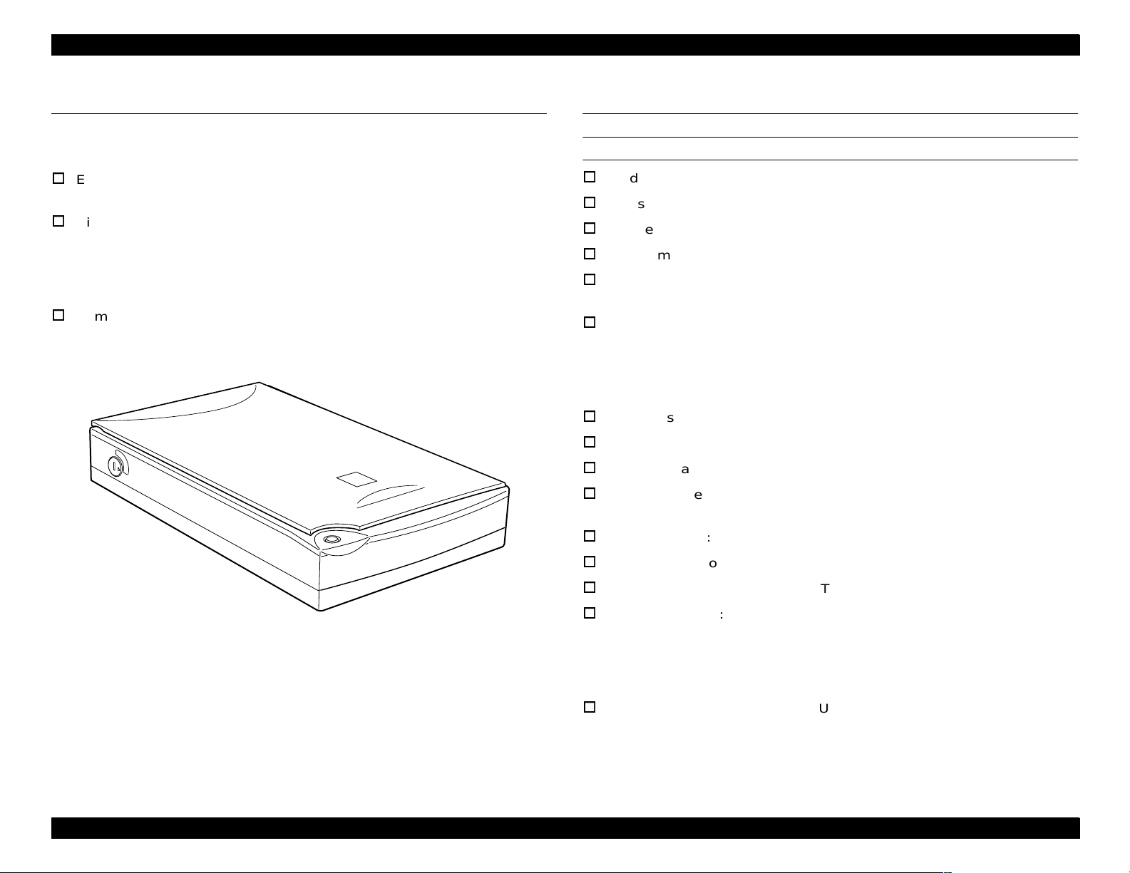
Figure 1-1. Exterior View of the Perfection 610
USB hosts: All of USB ports work correctly. (The
Microsoft Windows2000 will be supported.
iMac (AppleSystem8.5 or later, AppleSystem-
8.1 w/iMac Update 1.0)
PowerMacintosh G3 (AppleSystem8.5 or later)
functinality of the USB port(s) must be ensured
by the vendor of the Host.)
Product Description Features 8
Page 9
EPSON Perfection 610 Revision B
Number of hubs: This device must be in the Tier 1 or 2 with a
recommended USB cable.
(Tier 1: Host - this device, Tier 2: Host - Hub this device)
Light source: White cold cathode fluorescent lamp
Option: None
Operate switch: None
LED indicator: None
Start button: Ease of use with Page Manager
Scanning time: Color A4, Pentium 300MHz
300 dpi: 60 seconds
600 dpi: 280 seconds
EMC: FCC Part15 Subpart B Class B
CSA C108.8 Class B
AS/NZS3548 Class B
CISPR Pub22 Class B
CNS13438 Class B
CE Marking:
Low Voltage Directive 73/23/EEC EN60950
EMC Directive 89/336/EEC EN55022 Class B
EN61000-3-2
EN61000-3-3
EN50082-1
IEC 801-2/801-3/801-4
EPA: Energy Star Program
RESISTANCE TO ELECTRIC NOISE
ELECTRICAL SPECIFICATIONS
Static electricity: Panel: 10kV
Rated voltage: AC100-120V or AC220-240V
Input voltage: AC 100-120V ± 10% or AC 220-240V ± 10%
Rated current: 0.5A (Input AC 100V) or 0.3A (Input AC 200V)
Rated frequency range: 50-60Hz
Input frequency range: 49.5-60.5 Hz
Power consumption: Approximately 20 W
Insulation resistance: 10 M Ω at 500 VDC
(between AC line and chassis)
Dielectric strength: AC 1.5kV, 1 min
(between AC line and chassis)
Metal: 7kV / 150pF, 150
ENVIRONMENTAL CONDITIONS
Temperature: Operating: 5°C to 35 °C
Storage: -25
Humidity: Operating: 10 to 80%, no condensation
Storage: 10 to 85%, no condensation
°C to 60 °C
RELIABILITY
MCBF: 10,000 cycles
Ω
SAFETY, EMC, EPA
OPERATING CONDITIONS
Safety: UL1950 (UL)
CSA C22.2 No.950 (CSA)
EN60950 (VDE)
IEC950 (ROTEST, PSB)
Dust: Ordinary office or home conditions.
Extreme dust should be avoided.
Illumination: Operation under direct sunlight or near strong
light source is not guaranteed and should be
avoided.
Product Description Specifications 9
Page 10
EPSON Perfection 610 Revision B
DOCUMENT
Reflective type: Documents which has a smooth surface such as
printing and photograph.
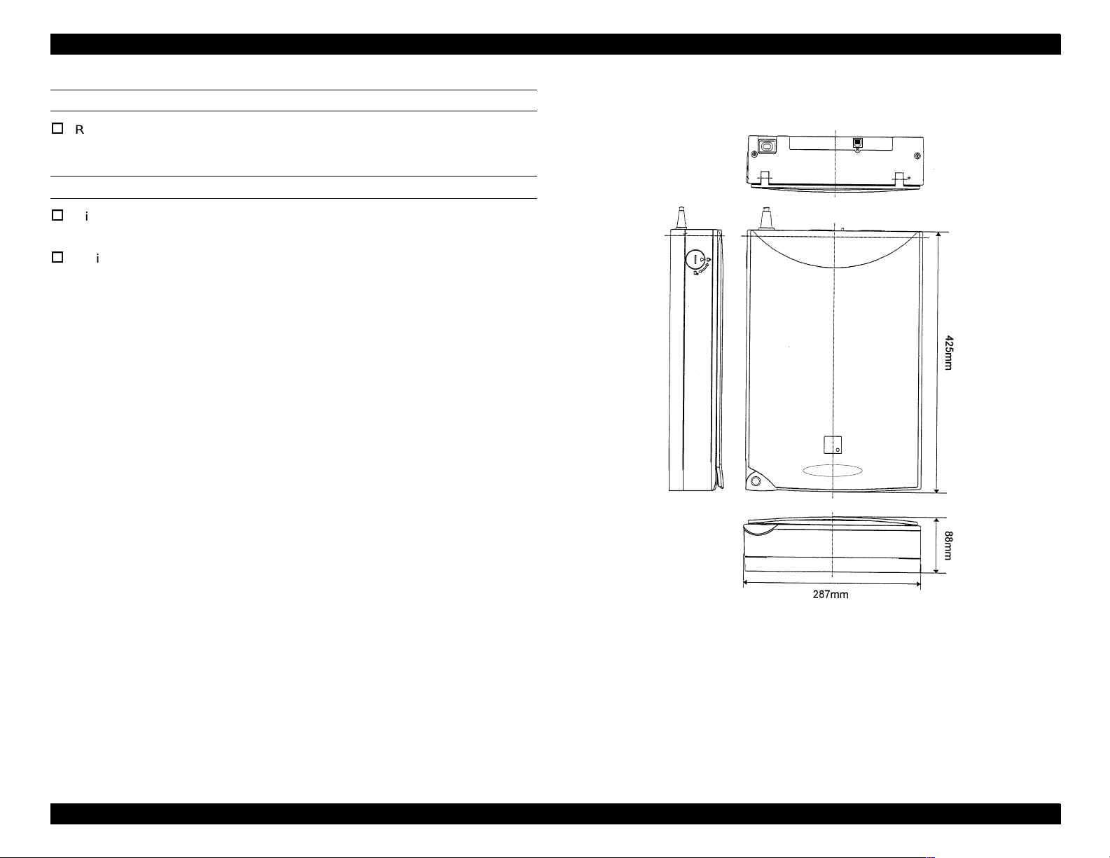
DIMENSION
Dimension: 287(W) x 425(D) x 88(H) mm
Refer to Figure 1-2.
Weight: 4.5 Kg
Figure 1-2. Exterior Dimension of the Perfection 610
Product Description Specifications 10
Page 11
EPSON Perfection 610 Revision B
1.3 Interface Specifications
This section provides specifications of the USB, the only interface supported by
the Perfection 610.
Table 1-2. Configuration
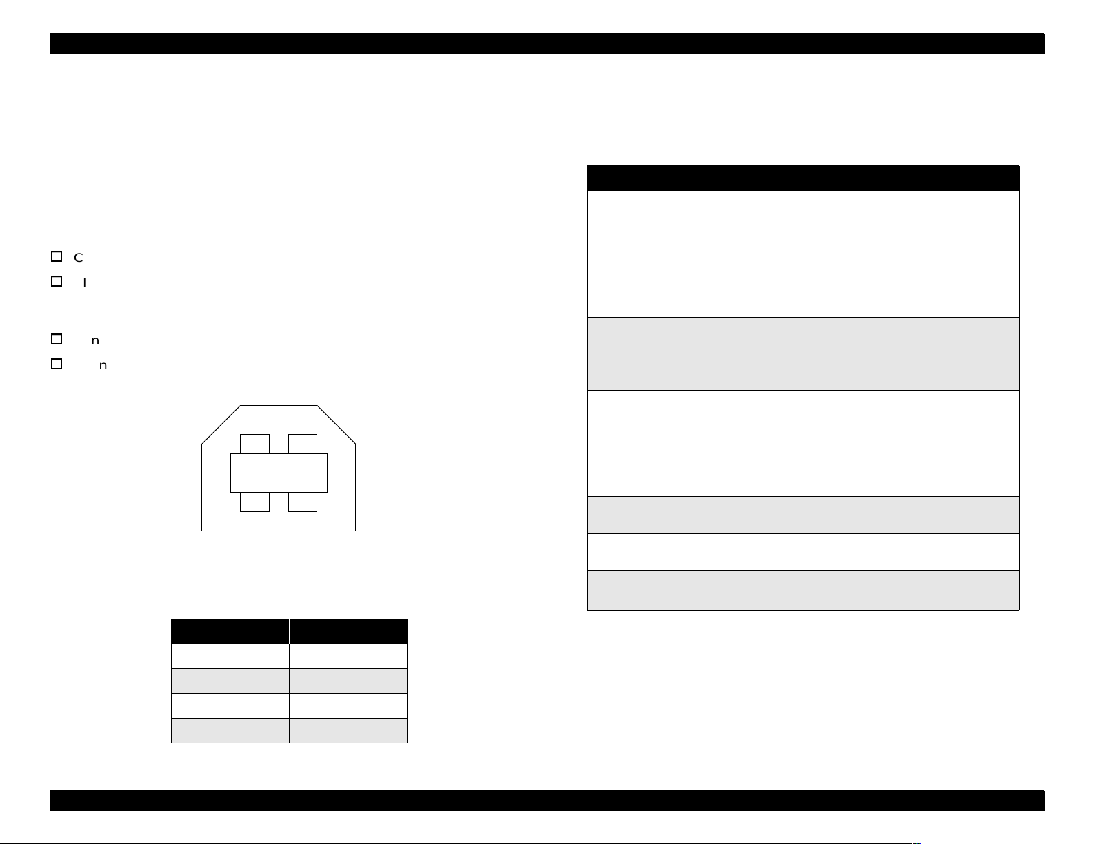
1.3.1 USB Specifications
Any items not included in this specification shall be in compliance with
Universal Serial Bus Specification Revision 1.0.
Configuration: See Table 1-2.
Electric specification: Compliant to Full Speed mode (12Mbit/s) of
Universal Serial Bus Specification Revision
1.0.
Connector: One Receptacle (Series B)
Connector Pin Assignment: See the following figure.
2
3
Figure 1-3. Connector Pin Location
Table 1-1. Connector Pin Assignment
1
4
Element Description
• Class: Vendor specific
• Subclass: Vendor specific
• Protocol: Vendor specific
Device
Configuration
Interface
Endpoint 1
Endpoint 2
String
Descriptor
• Maximum packet size for endpoint 0: 8byte
• Vendor ID: 0x04B8 (Seiko EPSON Corp.)
• Product ID: 0x0103
• Number of possible configurations: 1
• Number of interfaces supported by this configuration: 1
• Characteristics: Self-powered
• Remote wake up feature: Not supported
• Maximum of possible consumption: 2mA
• No Alternate setting
• Number of endpoints used by
this interface (excluding endpoint 0): 2
• Class: Vendor specific
• Subclass: Vendor specific
• Protocol: Vendor specific
• Bulk IN transfer
• Maximum data trans fer size: 64 byte
• Bulk OUT transfer
• Maximum data trans fer size: 64 byte
• iManufacturer: “EPSON”
• iProduct: “Scanner GT-6600” or “Perfection610”
Pin No. Signal
1VCC
2-Data
3+Data
4 GND
Product Description Interface Specifications 11
Page 12
EPSON Perfection 610 Revision B
1.4 Control Codes
The command level of this scanner is ESC/I-D1. The commands supported
are shown in the table below.
Table 1-3. Control Codes
Category Command Name Code
Request Identity ESC I
Request Identity 2 ESC i
Request Status ESC F
Execute Command
Request Extended Status ESC f
Start Scanning ESC G
Request Push Button Status ESC!
Set Data Format ESC D i
Set Resolution ESC R n1 n2
Set Data Format
Set Scanning Area ESC A n1 n2 n3 n4
Set Color ESC C i
Set Gamma Correction ESC Z i
Image Correction
Download Gamma Table ESC z i d[256]
1.5 Lamp Descriptions
Since this scanner does not have any LED indicator, it shows the various
conditions by turning on/off or blinking the lamp. Conditions indicated by the
lamp are as listed below:
Lamp: On
The scanner is in a normal condition.
Lamp: Blinking
The scanner is turned on before the transportation screw is unlocked.
Communication error
Fatal error except for lamp break has occurred.
NOTE:
Lamp: Off
The lamp goes off after 30 minutes.
Power save mode (Command is not received for 10 minutes.)
Power is not supplied.
The lamp has blown out.
The lamp was left blinking for 30 minutes.
Set Color Correction Factor ESC m d[9]
Set Threshold ESC t i
Auxiliary
Control
Set Scanning Mode ESC g i
Initialize ESC @
Set Line Counter ESC d i
Normal Response ACK
Abnormal Response NACK
Abort Scanning CAN
Header STX
Product Description Control Codes 12
Page 13
EPSON Perfection 610 Revision B
1.6 Error Indications
Refer to Section 1.5 for the error indications.
COMMAND ERROR
Cause: Undefined command is detected.
Disposition: The scanner ignores a wrong command and
parameter(s), so it keeps the current settings or
default value effective. The scanner sends
NACK and waits for the next command and
parameter(s).
Indicator: No effect
Remedy: Error condition is cleared when the scanner
receives a correct command.
Indicator: The lamp starts blinking. (The lamp goes off after
30 minutes.)
The lamp does not light up when it has blown.
Remedy: (After the cause of the error is removed)
Turn the scanner off and then back on.
Connect the USB cable again.
Receiving of ESC@
Acceptable command: [ESC F, ESC f, ESC @]
COMMUNICATION ERROR
Cause: Wrong procedure is detected in the interface
communication.
USB cable was removed during communication.
Disposition: The scanner stops the ongoing job.
Indicator: The lamp starts blinking. (The lamp goes off in
30 minutes.)
Remedy: Turn the scanner off and then back on.
Connect the USB cable again.
Acceptable command: None
FATAL ERROR
Cause: The lamp is broken.
The scanner is turned on before the
transportation lock is released.
System breakdown
Disposition: The scanner stops the ongoing job.
Product Description Error Indications 13
Page 14
EPSON Perfection 610 Revision B
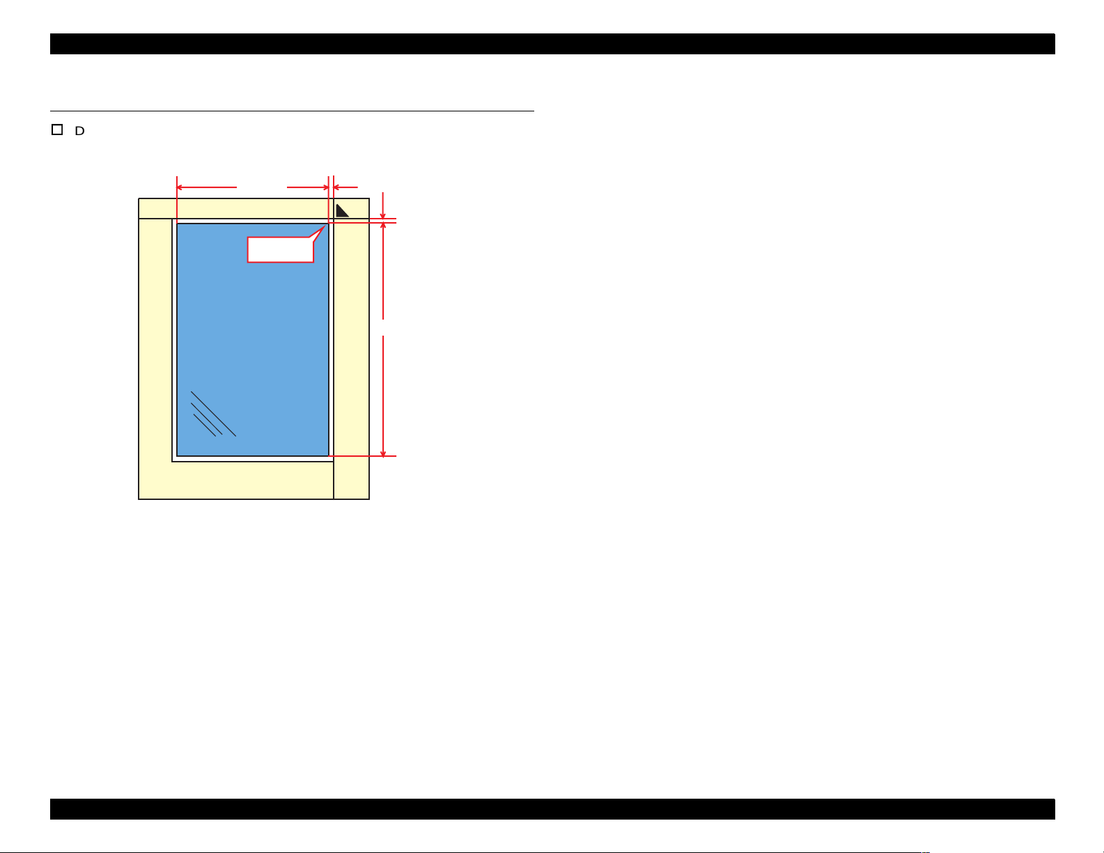
1.7 Manuscript Table
Dimension: 216 mm (Horizontal) x 297 mm (Vertical)
216 mm
Origin Point
Front
3 ± 2 mm
3 ± 2 mm
297 mm
Product Description Manuscript Table 14
Page 15

OPERATING PRINCIPLES
CHAPTER
2
Page 16
EPSON Perfection 610 Rev. B
CCD Sensor Board
2.1 Engine Mechanism
This section explains the engine functions and operating principles of the
EPSON Perfection 610. The engine mechanism has the two major parts; the
carriage unit (=scanning head) and the carriage move mechanism.
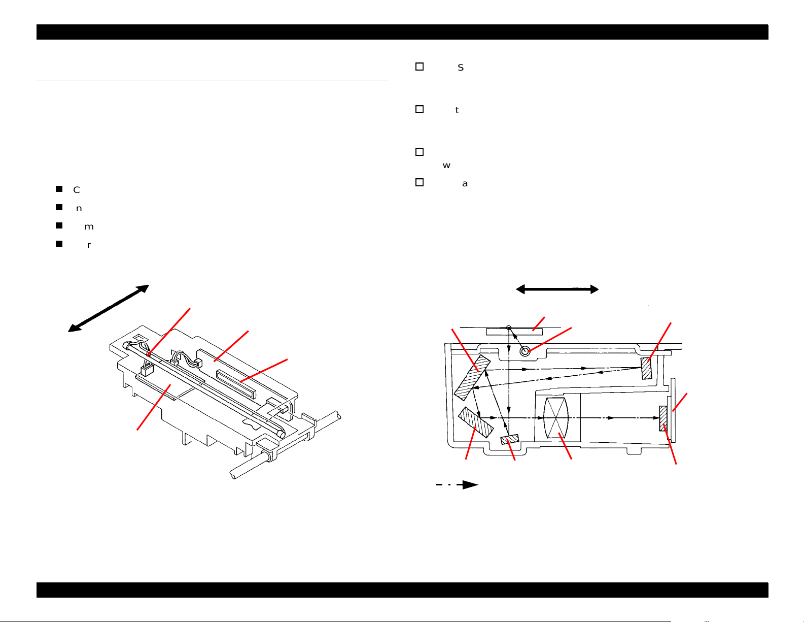
2.1.1 Carriage Unit
The carriage unit is composed of the following:
CCD sensor board (containing the CCD sensor)
Inverter board
Lamp (the light source)
Mirror and lens mechanism
This board includes the Color CCD line sensor (independent R,G,B) and
the sensor’s control and driver circuits.
Inverter Board
This board generates voltage used to drive the lamp. The board pressures
up +24VDC and converts it from direct current to alternating current.
Lamp
A white cold fluorescent lamp is used as the light source.
Mirror and Lens Mechanism
Light emitted to the document reaches the CCD sensor via the mirror and
lens mechanism in the carriage unit, where the light’s optical axis is
corrected. Note other scanners separates R/G/B components by switching
the light source between R, G, and B. In this scanner, however, it is
performed by the CCD sensor itself.
Front
Rear
Lamp
CCD Sensor Board
Inverter Board
Figure 2-1. Carriage Unit Component
CCD Sensor
Mirror 2
Mirror 4
Front
Mirror 1
Scanned Ima ge
Document
Lamp
Lens
Rear
Figure 2-2. Mirror, Lens Mechanism
Mirror 3
CCD Sensor
Board
CCD Sensor
Operating Principles Engine Mechanism 16
Page 17

EPSON Perfection 610 Rev. B
2.1.2 Carriage Drive Mechanism
A line-type color CCD sensor, which is included in the carriage unit, scans one
line at a time in the main scan direction (parallel to the carriage unit). To scan
next lines in the sub-scan direction after the first line, the scanner moves the
carriage unit with the CCD sensor in it along the sub-scan direction. The
scanned data is sent to the control board. Reading image for “n” line and
processing data for “N-1” line are simultaneously performed one after another.
1 Pixel
Second Line
Main Scan
Direction
Sub Scan Direction by CR Movement
First Line
The carriage unit slides in the sub-scan direction along the guide rail. To slide
the carriage, the carriage (CR) motor drives the timing belt attached to the
carriage unit by conveying torque via the drive pulley and transmission gear.
Scanning start position is determined by CR HP sensor, which is located on the
control board. Since the CR motor is a stepping motor, it is controlled under the
open loop system. (See Figure 2-4.)
CR HP Sensor
Carriage Unit
Drive Pulley
Timing Belt
Rear
CR Motor
Transmission
Gear
Driven Pulley
Figure 2-3. Carriage Movement
Front
Figure 2-4. Carriage Operation
Operating Principles Engine Mechanism 17
Page 18

EPSON Perfection 610 Rev. B
2.1.3 Power Supply Circuit
Power supply circuit board in this scanner generates direct current necessary
for driving the controller board and scanner engine.
See Table 2-1 and Table 2-2 for the power supply circuit board specifications
and the protection circuits for each output voltage/current, respectively. Figure
2-5 shows the power supply circuit diagram.
Table 2-1. Power Supply Circuit Board Specifications for Each Destinati o n
Specification Unit Part No. Fuse
100 -120 VAC Range 2031592 2.5 A / 125 VAC
220 -240 VAC Range 2031593 T2.5AH / 250 VAC
Table 2-2. Protection Circuits for Output Voltages/Curr ents
Output
Voltage
5 VDC 1.2A
12 VDC 0.2A
24 VDC 0.7A
*: Re covers within 5 minutes.
NOTE:
Output
Current
• The current is held 1A or less by the
fold-bac k characteristic.
• Recovers automatically*.
• The current is held 0.5 or less by the
fold-bac k characteristic of the
generator.
• Recovers automatically*.
• Shut down.
• To restore, turn the scanner power off
and then back on.
If any of the outputs is shut down, all the other outputs are also shut down.
Over Current Protection Over Voltage Protection
• Shut down.
• To restore, turn the scanner off and
then back on.
• The protection circui t becomes active
when the voltage rises to 5.5 - 7.5
VDC.
• Shut down.
• To restore, turn the scanner power off
and then back on.
• The protection circui t becomes active
when the voltage rises to 14 -17 VDC.
• Shut down.
• To restore, turn the scanner power off
and then back on.
• The protection circui t becomes active
when the voltage rises to 28 -33 VDC.
Operating Principles Engine Mechanism 18
Page 19

EPSON Perfection 610 Rev. B
F u ll W a v e
R e c tifie r C irc u it
F ilte r C ir c u it
AC Voltge Input
Sm oothing
Circuit
S w itc h in g
Circuit
Sm oothing
Circuit
+12VD C
R egulator IC
+5VD C
R egulator
Circuit
O v e r C u rre n t
Protection
Circuit
Sm oothing
Circuit
+24VD C
C o n tro l C irc u it
+24VD C O ver
C urrent Protectio n C irc u it
+ 5 /+ 1 2 /+ 2 4 V D C
O ver Voltage
Protection C ircuit
+12 VD C
+5 VD C
+24 VD C
To the M ain B oard To the S tart B utton
Figure 2-5. Power Supply Circuit Block Diagram
Operating Principles Engine Mechanism 19
Page 20

EPSON Perfection 610 Rev. B
(
)
2.1.4 Control Circuit
The CPU (IC11) of this scanner is a one-tip 16-bit bus CPU operating at
20MHz. ASIC (IC7) manages input signal correction, image processing, and
controlling the CCD sensor board and USB interface. Table 2-3 shows the
major IC functions.
Table 2-3. Major ICs
IC Location Functions
CPU
M37920 IC11
SDM4260CLU-6S IC3 DRAM 256k x 16bit
BA033FP-E2 IC9 Regulator IC (3.3 VDC)
NJM78M05DLA-TE1 IC12 Regulator IC (5 VDC)
E02A32SA IC7
A3957SLBTR IC1, 2 CR motor driver IC
M51953A IC8 Reset IC
AD9816JS IC24 12-bit A/D converter
M27C1001-10F1 IC5 Program ROM (128k x 8bit)
24-bit Address Bus
16-bit Data Bus
ASIC: Manages the following:
• Input image signal correction
• CCD control
• USB interface control
• Image processing
• Memory control
• Data in/output control
CCD Board
Lam p
&
Inverter B oard
R e g u la to r (IC 9 )
3.3V D C
DRAM
(IC 3 )
Im age D ata
(R /G /B )
E02A 32 (IC 7)
Address B us
D a ta B u s
CPU (IC11)
CLK
CR2
CR
Motor
AMP.
CR Motor
D river
(IC 1 , 2 )
H.P. Sensor
(P C 1 )
Figure 2-6. Control Circuit Diagram
R e g u la to r (IC 1 2 )
5VD C
CLK
(CR1)
USB
PRO M
(IC 5 )
Reset IC
(IC 8 )
SG-8002PHC CR1 48MHz clock for E02A32SA
CSTCS20.00 CR2 20MHz clock for CPU.
EE-SX1041 PC1 CR home position sensor
Operating Principles Engine Mechanism 20
Page 21

TROUBLESHOOTING
Page 22

EPSON Perfection 610 Revision B
3.1 Overview
This chapter describes troubleshooting procedures for this scanner.
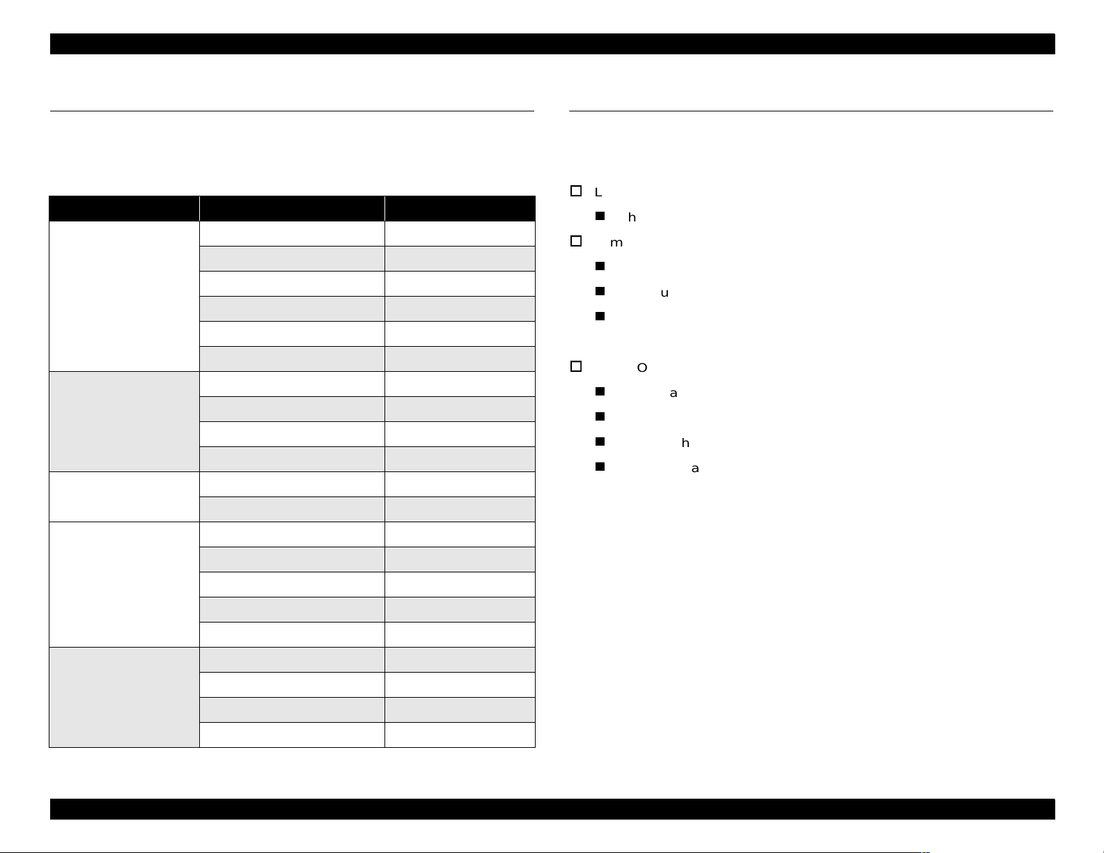
3.2 Self-Diagnostic Function
The self-diagnostic function of the scanner let s the scanner it self det ect
abnormal conditions. When the scanner detects an abnormality, it
shows an error using the lamp. See Table 3-1 for the error s detected by
the self-diagnostic function.
Table 3-1. Errors Detected by the Self-Diagnostic Function
Lamp Condition Error Type (Cause Remedy)
No effect
Blinking
(Goes off after 30
minutes.)
Off
(=the lamp ha s
blown out.)
Blinking
(=error except the
lamp has blown
out.)
Command Error
Cause:
Disposition:
Remedy:
Communication Error
Cause:
Disposition:
Remedy:
Acceptable command:
Fatal Error
Cause:
Disposition:
Remedy:
Acceptable command:
Undefined command
The scanner ignores the wrong command and
parameters, and returns NACK and waits for the
next command and parameters.
The scanner clears the error when it receives a
correct command and parameters.
Wrong communication procedure is detected.
USB is disconnected during communication.
The scanner turns the lamp off and stops
operating.
Turn the scanner off and back on.
Disconnect the USB cable and then connect it
properly.
The lamp has blown out.
The scanner is turned on or receives a
command with the transportation screw
locked.
The scanner is broken.
The scanner turns the lamp off and stops
operating.
After removing the cause of the problem,
Turn the scanner off and back on.
Send a ESC@ command.
Disconnect the USB cable and connect it
again.
None
[ESC F, ESC f, ESC @]
Troubleshooting Overview 22
Page 23

EPSON Perfection 610 Revision B
3.3 Troubleshooting
This section describes how to troubleshoot probl ems according to
exhibited phenomenons.
See Table 3-2 that enables you to find the defective part to the unit
level. Then refer to the corresponding table for checkpoints and
solutions.
Table 3-2. Problems and Corresponding Tables to Refer to
Phenomenon Problem Refer to:
The scanner is turned on but
does not operate.
“Fatal Error” occurs. The
scanner is turned off and back
on but still shows the same
error.
Image is not read clearly. Image is not read clearly. Table 3-7
“Communication Error” occurs .
Communication with the host
is attempted again, but the
same error occurs.
Table 3-3. The scanner is not Initialized.
Cause Step Checkpoints Finding Remedy
CN1 on the power
supply board is
disconnected.
1
The scanner is not initialized. Table 3-3
The carriage unit does not
operate.
The carriage unit operates but
the error is indicated.
The lamp does not light up. Table 3-6
USB interface error Table 3-8
Is CN1 on the power
supply board
disconnect ed?
Yes
Connect CN1 to the
power supply
board.
Table 3-4
Table 3-5
Table 3-4. The carriage unit does not operate.
Cause Step Checkpoints Finding Remedy
The PS
(Power
Supply)
board is
defective.
The carriage
drive
mechanism
is defective.
The CR
motor is
defective.
The main
board is
defective.
1 With scanner power on, ch eck
CN101 for the output voltage at
the pins below.
• Pins: 8/9 (+) and 6/7 (-)
• Voltage: +24VDC
Is grease (G-26) properly
applied?
2
(See Chapter 6.)
3 • With the upper housing
removed, turn the scanner on,
and check that the CR motor is
live.
• Remove the CR motor, and
check that the carriage unit
moves smoothly.
4 Disconnect CN6 on the main
board. Then, using a tester,
check that the coil resistance at
each point below is 6.2
1. Between Pins 2 and 4
2. Between Pins 1 and 3
5 Follow the steps below to check
for the CR motor driver circuit.
1. Set the meter to
2. Place the (-) terminal of the
tester on Pins 1, 2, 3, and then
4 of the CN6 on the main
board.
3. Place the (+) terminal of the
tester on Pin 6 or 7 of the CN4
on the main board.
4. Turn the scanner off, and
check that the meter shows
“for each pi n.
“
∞
6 --- --- Replace the main
.
Ω
.
Ω
No Replace the PS
board.
No Apply grease to
the specified
points properly.
No Check the
carriage unit, and
replace any
defective part or
disassemble an d
assemble the
scanner again.
No Replace the CR
motor and go to
step 4.
No Replace the main
board.
board.
Troubleshooting Troubleshooting 23
Page 24

EPSON Perfection 610 Revision B
Table 3-5. The carriage unit operates but the error is indicated.
Cause Step Checkpoints Finding Remedy
The CR home
position sensor
is defective.
Check the signal levels
1
between the collector (+)
and emitter (-) of PC1. The
signal level should change
depending on the conditio n
below:
•HIGH (4.5V) = Light is
blocked in PC1.
•LOW (0.3V) = Light
passes in PC1.
--- Replace the CR
home position
sensor (PC1) on
the main board.
Table 3-6. The lamp does not light up.
Cause Step Checkpoints Finding Remedy
CN5 on the
main board is
disconnect ed.
CN1 or CN2 on
the CCD sensor
board is
disconnected.
The connector
for the lamp is
not properly
connected to
the inverter
board.
The lamp is
defective.
The inverter
board is
defective.
The main board
is defective.
1 Check tha t CN5 is
disconnect ed.
2 Check that CN1 or CN2 on
the CCD sensor board is
disconnected.
3 Check that the co nnector is
properly connected to the
inverter board.
4 After replacing the lamp,
check that the lamp lights
up.
5 After replacing the inverter
board, check that the lamp
lights up.
6 --- --- Replace the main
Yes Connect CN5 on
the main board
properly.
Yes Connect CN1 or
CN2 on the CCD
sensor board
properly.
No Connect the
connector
properly.
Yes Replace the
lamp.
Yes Replace the
inverter board.
board.
Table 3-7. Image is not read clearly.
Cause Step Checkpoints Finding Remedy
Any mirror in the
carriage unit or
the surface of
the lamp is dirty.
The CCD
sensor board is
defective.
The main board
is defective.
1 After cleaning the mirror(s ),
check that image is read
clearly.
2 --- --- Replace the CCD
3 --- --- Replace the main
No Clean the
surface of the
lamp.
sensor board.
board.
Table 3-8. USB Interface Error
Cause Step Checkpoints Finding Remedy
The host or O/S
(Windows’98/
NT) does not
support USB.
The TWAIN
driver attached
for the scanner
is not prope rly
installed.
The USB cable
is defective.
The main board
is defective.
1 On the Windows, access
My Computer > Property >
Device Manager, and
check that Universal Serial
Bus Controller is effective.
2 Check that the driver for
the scanner is installed
properly.
3 After replacing the USB
cable, check that the error
is not indicated.
4 --- --- Replace the main
No Replace the host.
No Instal the correct
driver properly.
No Replace the USB
cable.
board.
Troubleshooting Troubleshooting 24
Page 25

ASSEMBLY AND DISASSEMBLY
CHAPTER
4
Page 26

EPSON Perfection 610 Revision B
4.1 Overview
This chapter describes procedures for disassemb li ng the EPSON
Perfection 610. Unless otherwise specified, the scanner can be
disassembled by reversing the disassembly procedures.
4.1.1 Precautions
W ARNING
CAUTION
The directions used in this chapter are defined as shown in Figur e 4-1.
Disconnect the power cable before disassembling or
assembling the scanner.
When servicing, note the points below:
Consider the size of the scanner and make enough
room for servicing.
Since this scanner is a precision equipement,
service it on a flat, level, heavy-duty table.
In s id e
R ear (B ack)
R ight
Left
Front
EPSON
4.1.2 Tools
Use the tools specified in Table 1-1.
Table 4-1. Tools
Names Availabi lity Part Number
Phillips screw driver (#2)
Standard screw driver
Pliers
Tweezers
B743800200
B743000100
B740400100
B641000100
4.1.3 Screws
The screws used in the scanner are as shown in Table 4-2. Make sure
you always use the correct type and number of screws for the
assembling part. See Table 4-3 for the screw appearances.
Table 4-2. Screw Specifications
Abbreviation Description
CP Cross-recessed Pan Head sc rew
CBS Cross-recessed Binding Head S-tite screw
CCP Cross-recessed Cup Head P-tite screw
Table 4-3. Screw Appearances
Head appearance
Top Side
Crossrecessed
Binding
Pan
Cup
Standard
- - - S-tite
B-tite
P-tite
Type Washer
With Outside Toot hed
lock washer
With Spring lock
washer
Figure 4-1. Directions
Assembly and Disassembly Overview 26
Page 27

EPSON Perfection 610 Revision B
4.2 Disassembly Procedures
4.2.1 Releasing the Carriage Lock
1. Using a standard screw driver, release the Carri age Lock locat ed at
the left side of the scanner body.
CAUTION
: Released
When locking the carriage for transporting the
scanner, make sure the carriage is at the home
position.
: Locked
Figure 4-2. Carriage Lock Location
Assembly and Disassembly Disassembly Procedures 27
Page 28

EPSON Perfection 610 Revision B
4.2.2 Document Cover Removal
1. Open the Document Cover.
2. Holding the Document Cover by the edges, release the two hooks
by pushing the cover to the rear as shown in Figure 4-4.
Document Cover
Hooks
Figure 4-3. Document Cover Removal (1)
Figure 4-4. Document Cover Removal (2)
Assembly and Disassembly Disassembly Procedures 28
Page 29

EPSON Perfection 610 Revision B
4.2.3 Upper Housing Removal
1. Release the Carriage Lock. (See Section 4.2.1.)
2. Remove the Document Cover. (See Section 4.2.2.)
3. Remove the two screws (gold, CBS, M3x6) at the back of the
scanner body.
4. Lifting up the rear end of the Upper Housing, release the three
hooks at the front end, and then remove the Upper Housing toward
the front.
Figure 4-6. Upper Housing Removal (2)
Three Hooks on the Front
CBS Screws (M3x6)
Figure 4-5. Upper Housing Removal (1)
Figure 4-7. After Removing the Upper Housing
Assembly and Disassembly Disassembly Procedures 29
Page 30

EPSON Perfection 610 Revision B
4.2.4 Inverter Lamp / Inverter Board Removal
1. Release the Carriage Lock. (See Section 4.2.1.)
2. Remove the Document Cover. (See Section 4.2.2.)
3. Remove the Upper Housing. (See Section 4.2.3.)
4. Remove the two screws (CCP, M3x8) on the Carriage Unit. (See
Figure 4-8.)
5. Using a standard screw driver, lift up the carriage cover in the
Carriage Unit, and then move it to the front to remove it. (See Fi gure
4-9.)
CCP Screws (M3x8)
Figure 4-8. Carriage Unit Disassembly (1)
Figure 4-9. Carriage Unit Disassembly (2)
Assembly and Disassembly Disassembly Procedures 30
Page 31

EPSON Perfection 610 Revision B
6. Disconnect the connector for the Inverter Lamp from the Inverter
Board.
7. Remove the black screw and disconnect the 2-pin connecto r for the
CCD sensor, and then remove the Inverter Board.
8. Remove the Inverter Lamp from the carriage cover.
CHECK
POINT
When installing the Inverter Lamp, locate the
connectors correctly as shown in the following
figures.
Connector
Inverter Board
Black Screw
Connector (2-pin)
Figure 4-10. Inverter Board Removal
Carriage Cover
Connector (2-pin)
Inverter Lamp
Figure 4-11. Inverter Lamp Removal
Assembly and Disassembly Disassembly Procedures 31
Page 32

EPSON Perfection 610 Revision B
4.2.5 Carriage Unit Removal
1. Release the Carriage Lock. (See Section 4.2.1.)
2. Remove the Document Cover. (See Section 4.2.2.)
3. Remove the Upper Housing. (See Section 4.2.3.)
4. Using a standard screw driver, remove the timing belt clamp
securing the timing belt and the carriage.
Timing Belt Clamp
Figure 4-12. Metal Clamp Removal
Assembly and Disassembly Disassembly Procedures 32
Page 33

EPSON Perfection 610 Revision B
5. Remove the hexagon nut at the rear end of the carriage guide shaft.
6. Remove the tension spring and the screw (gold, CBS, M3x4)
securing the driven pulley assembly.
Tension Spring
Figure 4-14. Driven Pulley Assembly Removal (1)
Hexagon Nut
Figure 4-13. Hexagon Nut Removal
CBS Screw (M3x4)
Figure 4-15. Driven Pulley Assembly Removal (2)
Assembly and Disassembly Disassembly Procedures 33
Page 34

EPSON Perfection 610 Revision B
7. Release the timing belt from the driven pulley.
8. Remove the driven pulley assembly by pushing it in the direction
indicated with the arrow. (See Figure 4-17.)
9. Remove the CR shaft from the Carriage Unit.
7.
Figure 4-17. Driven Pulley Assembly Removal (3)
Driven Pulley
Timing Belt
Carriage Unit
Figure 4-16. Timing Belt Removal
CR Shaft
Figure 4-18. Carriage Guide Shaft Removal
Assembly and Disassembly Disassembly Procedures 34
Page 35

EPSON Perfection 610 Revision B
10. Inserting a standard screw driver from the back, remove the FFC
metal clamp.
Carriage Unit
FFC Metal Clamp
FFC Cable
11. Release the FFC (white) from the connect or and the two guide tabs
in the Carriage Unit, and then remove the Carriage Unit.
Carriage Unit
Figure 4-20. Carriage Unit
Guide Tabs
Connector
Figure 4-19. FFC Metal Clamp and FFC Removal
Assembly and Disassembly Disassembly Procedures 35
Page 36

EPSON Perfection 610 Revision B
4.2.6 Carriage Motor / Timing Belt Removal
1. Release the Carriage Lock. (See Section 4.2.1.)
2. Remove the Document Cover. (See Section 4.2.2.)
3. Remove the Upper Housing. (See Section 4.2.3.)
4. Remove the Carriage Unit. (See Section 4.2.5.)
5. Remove the two screws (CBS, M3x4) securing t he FFC fi xing plate,
and then remove the FFC fixing plate.
6. Remove the three screws (gold, CBS, M3x4/M3x6) and the two
hooks at the rear edge, and then remove the main board cover.
7. Remove the two screws (gold, CBS, M3x4) securing the CR Motor
Unit, and then shift the CR Motor Unit inward.
8. Disconnect the cable for the CR Motor Unit from the connector on
the main board, and then remove the CR Motor Unit.
6. Hooks
5. FFC Fixing Plate
6. CBS Screws M3x6)
CR Motor Unit
Connector
CBS Screws (M3x4)
Figure 4-22. CR Motor Unit Removal (1)
6. Main Board Cover
6. CBS Screw (M3x4)
5. CBS Screws (M3x4)
Figure 4-23. CR Motor Unit Removal (2)
Figure 4-21. Shield Plate Removal
Assembly and Disassembly Disassembly Procedures 36
Page 37

EPSON Perfection 610 Revision B
9. Follow the steps below to remove the Timing Belt from the CR Motor
Unit.
1) Remove the E-ring.
2) Remove the transmission gear.
3) Disengage the timing belt from the drive pulley.
E-ring
Figure 4-24. Timing Belt Removal
Timing Belt
Timing Belt
E-ring
Transmission Gear
Drive Pulley
Transmission Gear
Figure 4-25. Parts in the CR Motor Unit
Assembly and Disassembly Disassembly Procedures 37
Page 38

EPSON Perfection 610 Revision B
4.2.7 Main Board Removal
1. Release the Carriage Lock. (See Section 4.2.1.)
2. Remove the Document Cover. (See Section 4.2.2.)
6. Hooks
3. Remove the Upper Housing. (See Section 4.2.3.)
4. Slide the Carriage Unit slowly until you see the whole main board
cover.
5. Remove the two screws (CBS, M3x4) securing t he FFC fi xing plate,
and then remove the FFC fixing plate.
6. Remove the three screws (gold, CBS, M3x4/M3x6), release t he two
hooks at the rear edge, and then remove the main board cover.
6. Main Board Cover
6. CBS Screws (M3x6)
5. CBS Screws (M3x4)
6. CBS Screw (M3x4)
4. Carriage Unit
5. FFC Fixing Plate
Figure 4-26. Main Board Removal (1)
Assembly and Disassembly Disassembly Procedures 38
Page 39

EPSON Perfection 610 Revision B
7. Remove the screw (CP, M3x5) near the I/F connector and the one
(CBS, M3x5) securing the Main Board.
Carriage FFC Connector
CN4 (Power Supply Unit)
8. Disconnect the followi ng cables f rom the corr esponding connectors;
CR Motor - CN6, carriage FFC, Power Supply Board - CN4.
9. Remove the Main Board.
CP Screw (M3x5)
Figure 4-27. Main Board Removal (2)
CN6 (CR Motor)
Figure 4-28. Main Board Removal (3)
CBS Screw (M3x5)
Figure 4-29. Main Board
Assembly and Disassembly Disassembly Procedures 39
Page 40

EPSON Perfection 610 Revision B
4.2.8 Panel Board Removal
1. Release the Carriage Lock. (See Section 4.2.1.)
2. Remove the Document Cover. (See Section 4.2.2.)
3. Remove the Upper Housing. (See Section 4.2.3.)
4. Remove the screw (gold, CBS, M3x4).
CHECK
POINT
In the following steps, manually move the carriage
back and forth slowly if necessary.
5. Disconnect the locking connector (pull and rel ease) for the Panel
Board from the Power Supply Board, and then remove the Panel
Board.
Connector
CBS Screw (M3x4)
Panel Board
Figure 4-30. Panel Board Removal
Assembly and Disassembly Disassembly Procedures 40
Page 41

EPSON Perfection 610 Revision B
4.2.9 Power Supply Board Removal
1. Release the Carriage Lock. (See Section 4.2.1.)
2. Remove the Document Cover. (See Section 4.2.2.)
3. Remove the Upper Housing. (See Section 4.2.3.)
CAUTION
In the following steps, manually move the carriage
back and forth slowly if necessary.
4. Release the locking connector (pull and releas e) for the Panel
Board, and then disconnect the cable from t he Power Supply Board.
(Refer to Figure 4-30.)
5. Disconnect the locking connector (pick and release) for the AC
cable from the Power Supply Board.
AC Cable
Connector for the AC Cable
Figure 4-31. Connectors for the Power Supply Board
Assembly and Disassembly Disassembly Procedures 41
Page 42

EPSON Perfection 610 Revision B
6. Remove the two screws (gold, CBS, M3x4) securing the shield
plate, and then remove it toward the inside.
7. Disconnect the cable from the locking connector (push and release) ,
remove the five screws (gold, CBS, M3x4), and then remove the
Power Supply Board from the shield plate.
CBS Screws (M3x4)
Shield Plate
Figure 4-32. Power Supply Board Removal (1)
CBS Screws (M3x4)
Connector
Figure 4-34. Power Supply Board
CBS Screws (M3x4)
Figure 4-33. Power Supply Board Removal (2)
Assembly and Disassembly Disassembly Procedures 42
Page 43

ADJUSTMENT
Page 44

EPSON Perfection 610 Revision B
This scanner needs no adjustment at the level of the service, including part replacement,
specified in Chapter 4 “Disassembly and Assembly”.
Adjustment 44
Page 45

MAINTENANCE
CHAPTER
6
Page 46

EPSON Perfection 610 Rev. B
6.1 Overview
This chapter provides information necessary to keep the scanner function in
optimum condition constantly and to prevent troubles.
6.1.1 Cleaning
Perform cleaning when stain is noticeable. Stain on the document glass,
particularly, has a direct effect on scanned images. Therefore, be sure to clean
the glass well to remove stain thoroughly.
CAUTION
Outer Cases
Wipe dirt off with a clean cloth, moistened with water and squeezed tightly.
To remove severe stains, use a neutral detergent.
Document Glass
Remove dust and paper debris with a dry, clean cloth. If the dirt is severe
or foreign matter is stuck on the glass, use a cloth soaked with neutral
detergent. If any trace is left, wipe it off with a dry, clean cloth again.
Never apply any organic solvents such as thinner or
benzene, since these may deteriorate plastic and rubber
parts.
Table 6-2. Lubrication Points
Figure Lubrication Points Lubrication
Table 6-1 Transmission gear shaft of the CR motor and
drive pulley shaft.
Figure 6-1 Driven pulley shaft G-26 (1x3 mm)
CAUTION
Excessive lubrication may cause the carriage
G-26 (1x3 mm) for
each
mechanism to be damaged or operate abnormally.
G-26
6.1.2 Lubrication
You need to lubricate the carriage unit if you have replaced it or notice it
making abnormal noise. See the following tables for the recommended grease
type and points to apply it.
Table 6-1. Recommended Grease
Grease Type Content s Pa rt Number Availability
G-26 40g B702600001 E *
*: EPSON exclusive (Not on the market)
Maintenance Overview 46
G-26
Figure 6-1. Lubrication Points
Page 47

APPENDIX
CHAPTER
7
Page 48

EPSON Perfection 610 Rev. B
7.1 Overview
This section provides useful information for servicing this sca nner.
7.1.1 Interconnection
Following figures shows interconnection of the scanner.
Lam p
(2 -p i n )
CN2
CN1
B071 ISN
B o a r d
(2 -p i n )
CN1
Inverter Board
B103MAIN Board
(18-pin) (4-pin)
CN5
CN4
CN2
CN6
CN7
(4 -p i n )
CR
Motor
USB
7.1.2 Connector Assignment
Table 7-1. Connector Summary- B103MAIN
Connector
Number
B103MAIN Board
CN4 To the Power Supply Board 12 Table 7-2
CN5 To the CCD Sensor Board 18 Table 7-3
CN6 To the CR Motor 4 Table 7-4
CN7 To the USB Cable 4 Table 1-1
Power Supply Board
CN1 AC Input 2 Table 7-5
CN101 To the Control Board 12 Table 7-2
CN102 To the Panel Board 5 Table 7-6
CCD Sensor Board
CN1 To the Control Board 18 Table 7-3
CN2 To the Inverter Board 2 Table 7-7
Inverter Board
CN1 To the CCD Sensor Board 2 Table 7-7
CN2 To the Lamp 4 Table 7-8
Description
Number
of Pins
Refer to:
(12-pin)
CN101
Power Supply Board
CN1
CN102
(5 -p i n )
CN1
(2 -p i n )
B103PNL
AC Plug
Figure 7-1. Interconnection (USB)
Appendix Overview 48
Page 49

EPSON Perfection 610 Rev. B
Table 7-2. Main Board - CN4
Pin No. Signal I/O
1, 2, 6, 7, 11, 12 GND -
3 +12V I
4, 5 +5V I
8, 9 +24V I
10 PM-SW I
Table 7-3. Main Board - CN5
Pin No. Signal I/O
1, 3, 5, 7, 8, 9, 10, 18 GND -
2 B I
4RI
6GI
11 SH O
12 12V O
13 F1X O
14 F2X O
15 RS O
16 5V O
17 24V O
Table 7-4. Main Board - CN6
Pin No. Signal I/O
1BXO
2AX O
3BO
4AO
Table 7-5. Power Supply Board - CN1
Pin No. Signal I/O
1AC (H)I
2AC (L) I
Table 7-6. Power Supply Board - CN102
Pin No. Signal I/O
1NC2NC 3 Push-SW I
4 NC 5GND-
Table 7-7. CCD Sensor Board - CN2
Pin No. Signal I/O
124VO
2GND I
Table 7-8. Inverter Board - CN2
Pin No. Signal I/O
1LAMPO
2LAMP O
Appendix Overview 49
Page 50

EPSON Perfection 610 Rev. B
7.2 Parts List and Explode Diagrams
Table 7-9. Parts List
Ref. # Description Ref. # Description Ref. # Description
100 FRAME,BASE 122 LOGO PLATE;E 146 MOTOR ASSY.,CR
101 HOUSING ASSY.,UPPER;ASP 123 EXTENSION SPRING,18.4 147 C.B.S. SCREW
102 KNOB,MOUNT,CARRIAGE 124 FOOT 148 C.B.(O) SCREW,4X4,F/ZG
103 MAT,COVER,DOCUMENT 125 BUSHING,HOUSING 14 9 TAPE,HOUSING
104 COVER,DOCUMENT 126 SHEET,COVER,25 180 LABEL,CARRIAGE LOCK
105 COVER,MAIN BOARD 127 SHEET,COVER,18 200 BOARD ASSY.,MAIN
106 KEYTOP,FUNCTION SWITCH 128 COVER,INLET 331 HARNESS
107 COMPRESSION SPRING,1.32 130 FERRITE CORE 300 BOARD ASSY.,POWER SUPPLY
108 HOUSING,PANEL 131 DOUBLE SIDE TAPE,28X10 330 HARNESS
109 SUPPORT,F-SW 132 COVER,FERRITE 400 POWER CABLE
110 LEVER,MOUNT,CARRIAGE 133 6N,5,F/ZN 401 I/F CABLE
111 COVER,P/S BOARD 134 SHAFT,CR 500 CARRIAGE ASSY.
112 SHEET,P/S BOARD 135 SHEET,SLIDE 502 BOARD ASSY.,INVERTER
113 TIMING BELT 136 RAIL,CR 503 LAMP ASSY.
114 PULLEY,DRIVE 137 COVER,SWITCH BOARD 504 COVER,CARRIAGE
115 FRANGE,PULLEY 138 BOARD ASSY.,PANEL 505 CLAMP,FERRITE CORE
116 PULLEY,IDLE 139 DOUBLE SIDE TAPE,22X50 506 FERRITE CORE
117 HOLDER ASSY.,PULLEY,DRIVE 140 SHEET,COVER,P/S BOARD 507 DOUBLE SIDE TAPE,28X10
118 CLAMP,TIMING BELT 141 C.B.S. SCREW 508 C.C.P-TITE,3X8,F/ZB
119 6N,3,F/ZN 143 C.P.SCREW 509 HARNESS
120 HOLDER ASSY.,PULLEY,DRIVEN 144 RETAINING RING 510 HARNESS
121 PULLEY,DRIVEN 145 C.B.S. SCREW 511 TAPE,HOUSING
Appendix Parts List and Explode Diagrams 50
Page 51

145
300
112
140
400
See P.2
500
104
141
138
137
330
139
145
124
140
141
100
124
135
136
145
111
145
145
128
145
132
130
131
145
143
120
127
147
123
141
145
105
200
115
121
145
134
144
146
117
145
119
133
119
114
115
113
116
118
144
122
106
107
108
109
148
148
103
101
181
331 (for 220/240V)
400 (for 120V)
180
102
183
147
147
149
149
110
401
125
127
127
127 126
126
127
GT-6600/PERFECTION 610 No.1 Rev.01 10123
Page 52

508
504
503
509
511
508
508
505
507
(NOT ASP.)
506
510
GT-6600/PERFECTION 610 No.2 Rev.01 10123
502
 Loading...