

Page 1
Page 2

IMPORTANT NOTICE
DISCLAIMER OF WARRANTY
Epson America makes no representations or warranties, either express or implied, by or
with respect to anything in this manual, and shall not be liable for any implied warranties
of merchantability and fitness for a particular purpose or for any indirect, special, or
consequential damages. Some states do not allow the exclusion of incidental or
consequential damages, so this exclusion may not apply to you.
COPYRIGHT NOTICE
All rights reserved. No part of this publication may be reproduced, stored in a retrieval
system, or transmitted, in any form or by any means, electronic, mechanical,
photocopying, recording, or otherwise, without the prior written permission of Epson
America, Inc. No patent liability is assumed with respect to the use of information
contained herein. Nor is any liability assumed for damages resulting from the use of the
information contained herein. Further, this publication and features described herein are
subject to change without notice.
TRADEMARKS
Epson is a registered trademark of Seiko Epson Corporation.
ActionNote is a trademark and Epson Connection is a service mark of Epson America, Inc.
General notice: Other product names used herein are for identification purposes only and
may be trademarks of their respective companies,
Copyright © 1993 by Epson America, Inc.
Torrance, California, USA
400275800
Page 3

EPSON
®
ActionNote
™
User’s Guide
4SLC2-50
Page 4

FCC COMPLIANCE STATEMENT
FOR AMERICAN USERS
This equipment has been tested and found to comply with the limits for a class B digital
device, pursuant to Part 15 of the FCC Rules. These limits are designed to provide
reasonable protection against harmful interference in a residential installation. This
equipment generates, uses, and can radiate radio frequency energy and, if not installed
and used in accordance with the instructions, may cause harmful interference to radio and
television reception. However, there is no guarantee that interference will not occur in a
particular installation. If this equipment does cause interference to radio and television
reception, which can be determined by turning the equipment off and on, the user is
encouraged to try to correct the interference by one or more of the following measures:
Reorient or relocate the receiving antenna
Increase the separation between the equipment and receiver
Connect the equipment into an outlet on a circuit different from that to which the
receiver is connected
Consult an experienced radio/TV technician for help
WARNING
The connection of a non-shielded equipment interface cable to this equipment will
invalidate the FCC Certification of this device and may cause interference levels that
exceed the limits established by the FCC for this equipment. It is the responsibility of the
user to obtain and use a shielded equipment interface cable with this device. If this
equipment has more than one interface connector, do not leave cables connected to unused
interfaces.
Changes or modifications not expressly approved by the manufacturer could void the
user’s authority to operate the equipment.
FOR CANADIAN USERS
This digital apparatus does not exceed the Class B limits for radio noise emissions from
digital apparatus as set out in the radio interference regulations of the Canadian
Department of Communications.
Le présent appareil numérique n’ émet pas de bruits radioélectriques dépassant les limites
applicable s aux appareils numériques de Classe B prescrites dans Ie règlement sur le
brouillage radioélectrique édicté par le Ministère des Communications du Canada.
ii
Page 5

MODEM FCC INFORMATION
FCC Part 68
This equipment complies with FCC rules, Part 68. On the underside of your computer is a
label that contains, among other things, the FCC Registration Number and Ringer
Equivalence Number (REN) for this equipment. You must, upon request, provide this
information to your telephone company.
An FCC compliant telephone cord and modular plug is provided with this equipment.
This equipment is designed to be connected to the telephone network or premises wiring
using a compatible modular jack which is Part 68 compliant. See the installation
instructions for details.
The Ringer Equivalence Number (REN) is useful to determine the quantity of devices you
may connect to your telephone line and still have all of those devices ring when your
telephone number is called. In most, but not all areas, the sum of the REN’s of all devices
connected to one line should not exceed five (5.0). To be certain of the number of devices
you may connect to your line, as determined by the REN, you should contact your local
telephone company to determine the maximum REN for your area.
Should this equipment cause harm to the telephone network, the telephone company shall,
where practical, notify the customer that temporary discontinuance of service may be
required; however, where prior written notice is not practical, the telephone company may
discontinue service forthwith, if such action is reasonable in the circumstances. You will be
informed of your right to file a complaint with the FCC.
The telephone company may make changes in its communications facilities, equipment,
operation procedures, where such action is reasonable, required in the operation of its
business and is not inconsistent with the rules and regulations of the Federal
Communications Commission. If they do, you will be notified in advance to give you an
opportunity to maintain uninterrupted telephone service.
Do not attempt to repair or modify this equipment. If defective, return it to the person
from whom it was purchased, who will in turn arrange to return it or to have it repaired
by the manufacturer or his authorized agent. The telephone company may ask that you
disconnect this equipment from the network until the problem has been corrected or until
you are sure that the equipment is not malfunctioning. If equipment is determined to be
malfunctioning, its use shall be discontinued until the problem has been corrected.
This equipment should not be used on coin service provided by the telephone company.
Connection to party line is subject to state tariffs.
WARNING
The connection of a telephone company line to this equipment, other than the one supplied
with the modem, will invalidate the FCC Certification of this device. It is the responsibility
of the user to connect and use only the ferrite-loaded telephone company line supplied
with this modem.
Changes or modifications not expressly approved by the manufacturer could void the
user’s autority to operate this equipment.
iii
Page 6

Important Safety Instructions
1.
Read all of these instructions and save them for later reference.
2.
Follow all warnings and instructions marked on the computer.
3.
Unplug the computer from the wall outlet before cleaning. Use a
damp cloth for cleaning; do not use liquid or aerosol cleaners.
4.
Do not spill liquid of any kind on the computer.
5.
Do not place the computer on an unstable cart, stand, or table.
6.
Slots and openings in the cabinet and the back or bottom are provided
for ventilation; do not block or cover these openings. Do not place
the computer near or over a radiator or heat register.
7.
Operate the computer using the type of power source indicated
on its label.
8.
If you plan to operate the computer in Germany, observe the
following safety precaution:
To provide adequate short-circuit protection and over-current
protection for this computer, the building installation must be
protected by a 16 Amp circuit breaker.
Beim Anschluß des Computers an die Netzversorgung muß
sichergestellt werden, daß die Gebäudeinstallation mit einem
16 A Überstromschutzschalter abgesichert ist.
9.
Connect all equipment to properly grounded (earthed) power outlets.
If you are unable to insert the plug into an outlet, contact your
electrician to replace your outlet. Avoid using outlets on the same
circuit as photocopiers or air control systems that regularly switch
on and off.
10.
Do not allow the computer’s power cord to become damaged or
frayed.
iv
Page 7

11. If you use an extension cord with the computer, make sure the total
of the ampere ratings of the devices plugged into the extension cord
does not exceed the ampere rating for the extension cord. Also,
make sure the total of all products plugged into the wall outlet does
not exceed 15 amperes.
12. Do not insert objects of any kind into this product through the
cabinet slots.
13. Except as specifically explained in this User’s Guide, do not attempt
to service the computer yourself. Refer all servicing to qualified
service personnel.
14. Unplug the computer from the wall outlet and refer servicing to
qualified service personnel under the following conditions:
A. When the power cord or plug is damaged.
B. If liquid has entered the computer.
C. If the computer does not operate normally when the operating
instructions are followed. Adjust only those controls that are
covered by the operating instructions. Improper adjustment of
other controls may result in damage and often requires
extensive work by a qualified technician to restore the computer
to normal operation.
D. If the computer has been dropped or the cabinet has been
damaged.
E. If the computer exhibits a distinct change in performance.
v
Page 8

Instructions Importances de Sécurité
1.
Lire complètement les instructions qui suivant et les conserver pour
réfénces futures.
2.
Bien suivre tous les avertissements et les instructions indiqués sur
l’ordinateur.
3.
Débrancher l’ordinateur de toute sortie murale avant le nettoyage.
Utiliser un chiffon humide; ne jamais utiliser un nettoyeur liquide
ou une bonbonne aérosol.
4.
Ne jamais renverser un liquide d’aucune sorte sur l’ordinateur.
5.
Ne pas placer l’ordinateur sur un chariot, un support, ou une table
instable.
6.
Les évents dans le meubles, à l’arrière et en dessous sent conçus pour
l’aération; on ne doit jamais les bloquer. Ne pas placer l’ordinateur
près d’une source de chaleur directe.
7.
Le fonctionnement de l’ordinateur doit s’effectuer conformément au
type de source d’alimentation indiquée sur l’étiquette.
8.
Lorsqu’on desire utiliser l’ordinateur en Allemagne, on doit observer
les normes sécuritaires qui suivent:
Afin d’assurer une protection adéquate à l’ordinateur contre les
court-circuits et le survoltage, l’installation de l’édifice doit
comprendre un disjoncteur de 16 amp.
9.
On doit brancher tout l’équipement dans une sortie reliée à la masse.
Lorsqu’il est impossible d’insérer la fiche dans la prise, on doit
retenir les services d’un électrician ou remplacer la prise. Ne jamais
utiliser une prise sur le même circuit qu’un appareil à photocopied
ou un système de contrôle d’aéation avec commutation
marche-arrêt.
10.
S’assurer que le cordon d’alimentation de l’ordinateur n’est pas
effrité.
vi
Page 9

11. Dans le cas où on utilise un cordon de rallonge avec l’ordinateur, on
doit s’assurer que la valeur totale d’ampèsres branchés dans le
cordon n’excède en aucun temps les amperes du cordon de rallonge.
La quantité totale des appareils branchés dans la prise murale ne
doit jamais excéder 15 ampères.
12. Ne jamais insérer un objet de quelque sorte que ce soit dans les cavités
de cet appareil.
13. Sauf tel que spécifié dans la notice d’utilisation, on ne doit jamais
tenter d’effectuer une réparation de l’ordinateur. On doit référer le
service de cet appareil à un technician qualifié.
14. Débrancher l’ordinateur de la prise murale et confier le service au
personnel de service qualifié selon les conditions qui suivent:
A. Lorsque le cordon d’alimentation ou la prise sent
endommagés.
B. Lorsqu’un liquide s’est infiltré dans l’ordinateur.
C. Lorsque l’ordinateur refuse de fonctionner normalement
même en suivant les instructions. N’ajuster que les commandes
qui sent énumérées dans les instructions de fonctionnement.
Tout ajustement inadéquat de tout autre contrôle peut
provoquer un dommage et souvent nécessiter des réparations
é1aborées par un technician qualifié afin de remettre l’appareil
en service.
D. Lorsqu’on a échappé l’ordinateur ou que l’on a endommagé le
boîtier.
E. Lorsque l’ordinateur démontre un changement noté au niveau de
sa performance.
vii
Page 10

Contents
INTRODUCTION
Standard Configuration . . . . . . . . . . . . . . . . . . . . . . . . . 1
Optional Equipment . . . . . . . . . . . . . . . . . . . 3
Where to Get Help . . . . . . . . . . . . . . . . . . . . . . . . . . . . 3
How to Use This Manual . . . . . . . . . . . . . . . . . . . . . . . . 5
Conventions Used in This Manual . . . . . . . . . . . . . . . 6
CHAPTER 1 SETTING UP THE COMPUTER
Identifying the System Parts . . . . . . . . . . . . . . . . . . . . . .
Front View . . . . . . . . . . . . . . . . . . . . . . . . . . . . .
Rear Panel and Left Side . . . . . . . . . . . . . . . . . . . . .
Connecting the AC Adapter . . . . . . . . . . . . . . . . . . . . . .
Opening the Screen . . . . . . . . . . . . . . . . . . . . . . . . . . .
Connecting the Trackball . . . . . . . . . . . . . . . . . . . . . . . .
Turning On the Computer . . . . . . . . . . . . . . . . . . . . . . .
CHAPTER 2 USING YOUR COMPUTER
Taking Care of the Computer . . . . . . . . . . . . . . . . . . . . .
Backing Up the VGA Utilities . . . . . . . . . . . . . . . . . . .
Using the Password Function . . . . . . . . . . . . . . . . . . . . .
Typing the Password . . . . . . . . . . . . . . . . . . . . . . .
Using the Keyboard . . . . . . . . . . . . . . . . . . . . . . . . . . .
Special Keys . . . . . . . . . . . . . . . . . . . . . . . . . . . .
Using F11 and F12 . . . . . . . . . . . . . . . . . . . . . . . .
Using the Embedded Numeric Keypad . . . . . . . . . . . . .
Resetting the Computer . . . . . . . . . . . . . . . . .
Turning Off the Computer . . . . . . . . . . . . . . . . . . . .
Changing the CPU Speed . . . . . . . . . . . . . . . . . . . . . . . .
Using the LCD Screen . . . . . . . . . . . . . . . . . . . . . . . . . .
1-2
1-2
1-5
1-7
1-9
1-10
1-11
2-2
2-3
2-3
2-4
2-5
2-6
2-8
2-8
2-9
2-10
2-10
2-11
ix
Page 11

Using Diskettes . . . . . . . . . . . . . . . . . . . . . . 2-11
Inserting and Removing Diskettes . . . . . . . . . . . . . . . . 2-12
Write-protecting Diskettes . . . . . . . . . . . . . . . . . 2-13
Making Backup Copies . . . . . . . . . . . . . . . . . . .2-14
Using a Single Diskette Drive System . . . . . . . . . . . . . . 2-14
Using a Hard Disk . . . . . . . . . . . . . . . . . . . . . . . . . 2-15
Backing Up the Hard Disk . . . . . . . . . . . . . . . . . 2-15
Using Memory . . . . . . . . . . . . . . . . . . . . . . . . . 2-16
CHAPTER 3 POWERING THE COMPUTER
Using the AC Adapter . . . . . . . . . . . . . . . . . . . . . . . 3-1
Using the Battery Pack . . . . . . . . . . . . . . . . . . . . . . 3-2
Replacing the Battery Pack . . . . . . . . . . . . . . . . . . . 3-2
Recharging the Battery . . . . . . . . . . . . . . . . . . . . . . 3-5
Low Battery Indicator . . . . . . . . . . . . . . . . . . . . 3-6
Using the Suspend/Resume Switch . . . . . . . . . . . . . . . . . 3-7
Using Setup to Conserve Battery Power . . . . . . . . . . . . . . . 3-8
CHAPTER 4 CONNECTING OPTIONAL DEVICES
Connecting an External Monitor . . . . . . . . . . . . . . . . . . . . 4-2
Connecting a Parallel Printer . . . . . . . . . . . . . . . . . . . . . . 4-4
Connecting a Serial Device . . . . . . . . . . . . . . . . . . . . 4-5
Checking the Serial Port Settings . . . . . . . . . . . . . . . . 4-7
Using the EXT KB Port . . . . . . . . . . . . . . . . . . 4-7
Connecting An Optional Pointing Device . . . . . . . . . . . 4-8
Connecting an External Keyboard . . . . . . . . . . . . . . . . 4-8
Connecting the Internal Fax/Modem . . . . . . . . . . . . . . . . 4-9
Adding Memory Modules or a Numeric Coprocessor . . . . . . 4-10
Removing the Keyboard . . . . . . . . . . . . . . . . . . 4-11
Installing a Memory Module. . . . . . . . . . . . . . . . . . . 4-13
Installing a Numeric Coprocessor . . . . . . . . . . . . . . . 4-16
Replacing the Keyboard . . . . . . . . . . . . . . . . . . . . . 4-18
x
Page 12

CHAPTER 5 RUNNING SETUP
Starting the Setup Program . . . . . . . . . . . . . . . . . . . . 5-2
Changing the Settings . . . . . . . . . . . . . . . . . . . . 5-3
Automatically Configuring Your System . . . . . . . . . . . . 5-4
Saving Your Selections . . . . . . . . . . . . . . . . . . . 5-4
Changing the Standard CMOS Setup . . . . . . . . . . . . . . . . . 5-5
Changing the Advanced CMOS Setup . . . . . . . . . . . . . . . . 5-7
Changing the Advanced Chipset Setup . . . . . . . . . . . . . . . . 5-10
Changing the Password . . . . . . . . . . . . . . . . . . . . . .. . . . 5-12
Hard Disk Utility . . . . . . . . . . . . . . . . . . . . . . . . . . 5-13
Hard Disk Format . . . . . . . . . . . . . . . . . . . . . . 5-14
Auto Interleave . . . . . . . . . . . . . . . . . . . . . . . . 5-15
Media Analysis . . . . . . . . . . . . . . . . . . . . . . . . 5-15
CHAPTER 6 USING THE VGA UTILITIES
Microsoft Windows, Version 3.1 . . . . . . . . . . . . . . . . . . . . 6-2
Using the VGACONF Utility Program . . . . . . . . . . . . . . . . 6-3
Viewing the Display Status. . . . . . . . . . . . . . . . . . . . 6-4
Changing Settings with Select Option . . . . . . . . . . . . . . 6-4
Setting the Standby Timer . . . . . . . . . . . . . . . . . . . . 6-6
Using VGACONF From the Command Line . . . . . . . . . . 6-7
APPENDIX A TROUBLESHOOTING
Identifying Your System . . . . . . . . . . . . . . . . . . . . . . .. A-2
Error Messages . . . . . . . . . . . . . . . . . . . . . . . . . . . . .. A-3
The Computer Won’t Start . . . . . . . . . . . . . . . . . . . . . .. A-3
Battery Problems . . . . . . . . . . . . . . . . . . . . . . . . . . . .. A-4
AC Adapter Problems . . . . . . . . . . . . . . . . . . . . . . . . .. A-5
The LCD Screen Is Blank . . . . . . . . . . . . . . . . . . . . . . .. A-6
The External Monitor Screen Is Blank . .. . . . . . . . . . . . . . . . A-6
The Computer Locks Up . . . . . . . . . . . . . . . . . . . . . . .. A-7
Password Problems . . . . . . . . . . . . . . . . . . . . . . . . . .. A-8
Diskette Problems. . . . . . . . . . . . . . . . .. A-9
Diskette Drive Problems . . . . . . . . . . . . . . . . . . . . . . .. A-10
Hard Disk Problems .. . . . . . . . . . . . . . .. A-10
Software Problems . . . . . . . . . . . . . . . . . . . . . . . . . . .. A-11
xi
Page 13

Printer Problems . . . . . . . . . . . . . . . . . . . . . . . . . . . A-12
Memory Module Problems . . . . . . . . . . . . . . . . . . . . . A-12
Trackball or Pointing Device Problems . . . . . . . . . . . . . . . . A-13
External Keyboard Problems . . . . . . . . . . . . . . . . . . . . . . A-13
Numeric Coprocessor Problems . . . . . . . . . . . . . . . . . . . . A-14
CMOS Battery Problems . . . . . . . . . . . . . . . . . . . . . . . A-14
APPENDIX B FAX/MODEM
Built-in Command Set . . . . . . . . . . . . . . . . . . . . . . . . . .
When to Issue Built-in Commands . . . . . . . . . . . . . . .
AT Command Summary . . . . . . . . . . . . . . . . . . . . . . . .
Dial Modifiers . . . . . . . . . . . . . . . . . . . . . . . . . . .
MNP Command Summary . . . . . . . . . . . . . . . . . . . . . . .
AT Register Summary. . . . . . . . . . . . . . . . . . . . . . . . . .
Option Registers . . . . . . . . . . . . . . . . . . . . . . . . . . .
MNP Register Summary. . . . . . . . . . . . . . . . . . . . . . . .
Result Code Summary . . . . . . . . . . . . . . . . . . . . . . . . .
B-3
B-3
B-4
B-6
B-7
B-10
B-11
B-14
B-15
APPENDIX C SPECIFICATIONS
Main Unit . . . . . . . . . . . . . . . . . . . . . . . . . . . . . . . .. C-l
Controllers . . . . . . . . . . . . . . . . . . . . . . . . . . . . . . .. C-2
Keyboard . . . . . . . . . . . . . . . . . . . . . . . . . . . . . . . .. C-3
Mass Storage . . . . . . . . . . . . . . . . . . . . . . . . . . . . . .. C-3
LCD Display . . . . . . . . . . . . . . . . . . . . . . . . . . . . . .. C-3
Power Supply . . . . . . . . . . . . . . . . . . . . . . . . . . . . .. C-3
Physical Dimensions . . . . . . . . . . . . . . . . . . . . . . . . . C-4
Environmental Requirements. . . . . . . . . . . . . . . . . . . . . . C-4
Power Source Requirements . . . . . . . . . . . . . . . . . . . . . . C-5
GLOSSARY
INDEX
xii
Page 14

Introduction
With your purchase of the Epson® ActionNote™ 4SLC2-50
computer, you have chosen state-of-the-art notebook computing.
The 486SLC2-50 microprocessor chip, designed for portable
computers, provides high-speed performance in a compact,
lightweight, notebook-size form.
Standard Configuration
The ActionNote is a versatile computer supporting a wide range of
applications and hardware. Its standard features include the
following:
4MB or 8MB of RAM (random access memory), expandable to
a maximum of 8MB
640 x 480 VGA (video graphics array), backlit, monochrome
LCD (liquid crystal display) screen, which emulates VGA
color with 32 shades of gray
Internal hard disk drive
Internal 3½-inch, 1.44MB diskette drive
Parallel port for a printer or other parallel device
Two serial ports for serial devices
RJ-11 standard phone jack for an internal modem
Video port for an external color or monochrome VGA monitor
®
Port for a PS/2
Mouse/keyboard adapter for simultaneously attaching an
external PS/2-type keyboard and a pointing device
-compatible pointing device
Introduction
1
Page 15

Rechargeable battery pack
AC adapter for powering the computer and recharging the
battery pack
Socket for an optional numeric coprocessor
Two processing speeds: high and low (8 MHz)
Suspend mode to save battery power
Carrying case with room for the computer, AC adapter, power
cable, diskettes, and manuals.
Trackball or other pointing device with drivers and utilities
®
MS-DOS
Microsoft
operating system, including diskettes and manuals
®
Windows,™ including diskettes and manuals.
Depending on the configuration you purchased, your computer
may also include the following:
Internal 9600/2400 fax/modem
Internal 14.4/14.4 fax/modem
BitCom
software, including diskettes and manuals.
2 Introduction
®
modem software and WinFax™ LITE fax transmission
Page 16

Optional Equipment
You can easily upgrade your computer by installing additional
memory and adding optional devices, including:
Expansion memory module (6MB)
External PS/2-compatible keyboard
Extra battery packs
Adapter for an automobile cigarette lighter
Fax/modem (installed by dealer only).
Where to Get Help
If you purchased your computer in the United States,
Epson America provides local customer support and service
through a nationwide network of Authorized Epson Service
Centers. Epson also provides support services through the Epson
Connection at: 1-800-922-8911.
Call the Epson Connection for the following:
Technical assistance with the installation, configuration, and
operation of Epson products
Sales of accessories, manuals, or parts for your Epson products
Assistance in On-Site Warranty Service for your Epson
products
Assistance in locating your nearest Authorized Epson Reseller
or Service Center
Introduction 3
Page 17

Customer relations
Epson technical information library fax service-also available
directly by calling (310) 782-4214
Product literature with technical specifications on current and
new products.
When you call for technical assistance, you need to be able to
identify your system and its configuration, and provide any error
messages to the support staff. See Appendix A for more
information.
If you purchased your computer in the United States, Epson also
provides On-Site Warranty Service. Your ActionNote package
should contain a packet describing the program. If a packet is not
included, call the Epson Connection for information. For your
convenience there is a sticker located on the bottom of your
computer with the number to call for product support and On-Site
Warranty Service.
If you purchased your computer outside the United States, please
contact your Epson dealer or the marketing location nearest you
for customer support and service. International marketing
locations are listed on the inside back cover of this manual.
If you need help with DOS, Windows, or any software application
program you are using, see the documentation that came with the
program for technical support information.
4 Introduction
Page 18

How to Use This Manual
This manual explains how to setup and operate your computer
and install options.
You do not need to read everything in this book to use your
computer; see the following chapter summaries to find the sections
you need:
Chapter 1 provides steps for setting up your computer.
Chapter 2 covers basic information about using the computer.
Chapter 3 explains how to power your computer using the AC
adapter and the battery. It also describes ways to conserve battery
power.
Chapter 4 describes how to connect optional devices.
Chapter 5 describes how to run the Setup program; this is
necessary if you want to set a password or you change the
configuration of your computer.
Chapter 6 describes the VGA utilities provided with your system.
Appendix A
Appendix B
modem and summarizes its commands.
provides troubleshooting tips.
provides basic information about the internal
Appendix C contains the specifications for your ActionNote
computer.
At the end of the manual, you’ll find a Glossary and an Index.
Introduction 5
Page 19

Conventions Used in This Manual
This manual uses the following type conventions to represent
commands:
Example Meaning
Enter Keys you press on the keyboard
Ctrl C
Fn F1 the letter C, or hold down the key marked
C:
\DOS
DISKCOPY A: B:
path \fileneme
COM 1
Keys you press at the same time; hold
down the key marked Ctrl and then press
Fn and then press the F1 key
Text as it appears on the screen
Text that you type exactly as shown
Words printed in lowercase italics
represent optional parameter names;
here you would type the actual path and
filename, such as \WORK\CONTACT
Names of hardware elements
6 Introduction
Page 20

Chapter 1
Setting Up the Computer
This chapter describes how to complete the basic setup of your
ActionNote computer. It covers:
Identifying the system parts
Connecting the AC adapter
Opening the screen
Connecting the trackball
Turning on the computer.
Instructions for installing optional equipment (such as a memory
module or a numeric coprocessor) or connecting external
equipment (such as a monitor or printer) are provided in
Chapter 4.
Caution
When travelling by airplane, be sure to take your computer into
the passenger compartment as carry-on luggage to prevent it
from being stored in an unpressurized storage area.
Setting Up the Computer 1-1
Page 21
Identifying the System Parts
Before getting started, refer to the illustrations below to identify
the different parts of your computer.
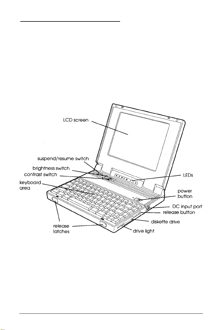
Front View
The main components on the front and right side of the
ActionNote are shown below.
1-2 Setting Up the Computer
Page 22

LCD screen
Your ActionNote has a backlit, monochrome LCD that supports
VGA resolutions up to 640 x 480 dots in 32 shades of gray.
Suspend/resume switch
Slide this switch to the right to suspend power to the computer
when it is on. This places the computer in a very low power
consumption state. Slide the switch to the left or press shift to
return the computer to its previous state.
Brightness switch
This switch controls the brightness of the LCD screen. Slide
the switch to the right to lighten the screen and to the left to
darken it.
Contrast switch
This switch controls the contrast on the LCD screen. Slide
the switch to the right to increase contrast and to the left to
decrease it.
Keyboard area
This is where you type commands and enter data. For a full
description, see Chapter 2.
Release latches
Slide these latches outward to release the top cover and open the
LCD screen.
Setting Up the Computer 1-3
Page 23
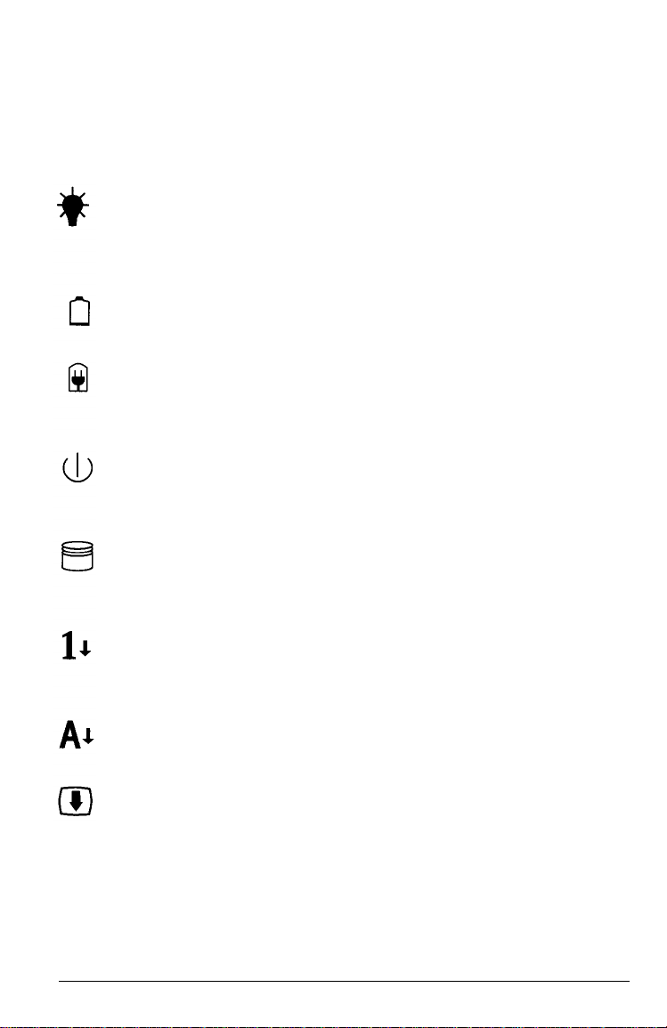
LEDs
The LEDs (light emitting diodes) on your computer provide
information about its operation,
Power—Indicates the computer is on; either the AC
adapter, battery pack, or automobile adapter is supplying
power to the computer.
Low battery—When flashing, indicates the battery
capacity is less than 20%.
Charging—Indicates the battery is fully charged; blinks
when the AC adapter is connected and charging the
battery.
Suspend mode—Indicates the computer is in Suspend
mode.
Hard disk drive-Indicates the computer is accessing the
hard disk drive.
1-4
Num Lock—Indicates that Num Lock is set on the
keyboard. This activates the embedded numeric keypad
on the keyboard.
Caps Lock—Indicates that Caps Lock is set on the
keyboard.
Scroll Lock—Indicates that Scroll Lock is set on the
keyboard.
Setting Up the Computer
Page 24

Power button
This button turns the computer on and off.
DC input port
Connect the AC adapter cable here. See page 1-8 for instructions.
Release button
Press this button to eject a diskette from the drive.
Diskette drive
Your computer includes a 3½-inch, 1.44MB diskette drive. For
instructions on using diskettes, see Chapter 2.
Drive light
This light is on when the computer is accessing the diskette drive.
Rear Panel and Left Side
The components on the rear panel and left side of the computer
are shown below.
Setting Up the Computer
1-5
Page 25

Battery compartment cover
Turn the computer upside down and open this cover to access the
battery pack. The rechargeable NiCad battery pack powers your
computer when the AC adapter is not connected. For a full
description, see Chapter 3.
External VGA port (VIDEO)
You can connect a VGA monochrome or color monitor to this port.
The ActionNote can display information on both the LCD screen
and an external monitor at the same time.
Parallel port (PRINTER)
You can connect a parallel device, such as a printer, to this port.
See Chapter 4 for instructions.
Serial port (COM 1)
This port supports a serial (RS-232C) device. See Chapter 4 for
more information.
Serial port (COM 2)
This port supports a serial (RS-232C) device. See Chapter 4 for
more information. Note that when the internal fax/modem is
installed, this port is disabled.
Phone jack (LINE)
Use this standard RJ-11 jack to connect a phone line when the
internal fax/modem is installed.
1-6 Setting Up the Computer
Page 26

External keyboard port (EXT KB)
Use this port to connect any PS/2-compatible pointing device. This
port also supports a mouse/keyboard adapter for attaching both
an external PS/2-type keyboard and a pointing device at the same
time. See Chapter 4 for instructions on installing optional devices.
Connecting the AC Adapter
The AC adapter is designed to be used in most countries, as it can
operate in the ranges 100 to 240 VAC, 50 to 60 Hz (auto-sensing).
Caution
Use only the AC adapter (model number AP-3S25) supplied
with the computer.
If you are using the adapter in a country other than the one where
you purchased your ActionNote, make sure you have the correct
power cable for the electrical socket. See the power cable
specifications in Appendix C for details.
You may need to connect the AC adapter to charge the battery
before you use it for the first time. (See Chapter 3 for complete
instructions on powering the computer with the AC adapter
and/or the battery.)
Setting Up the Computer 1-7
Page 27
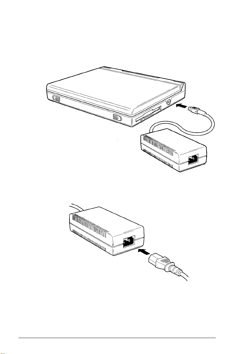
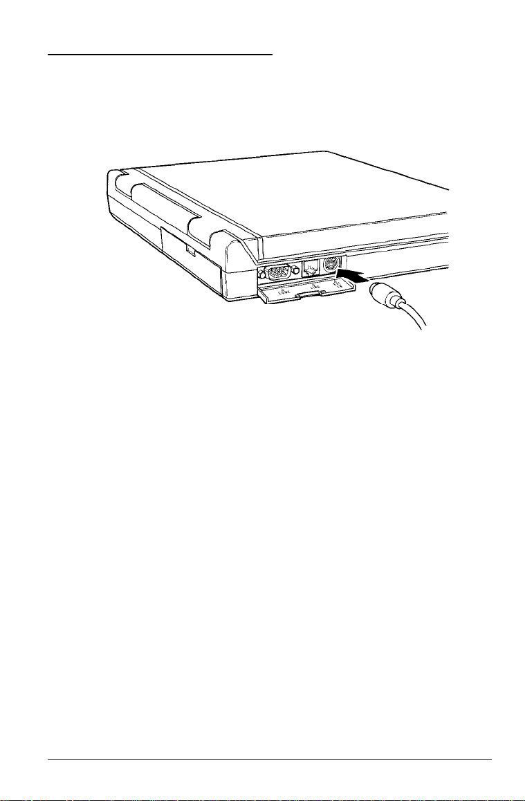
Follow these steps to connect the adapter to the computer:
1. Connect the AC adapter plug to the DC input port on the right
side of the computer.
2. Connect the power cable to the AC adapter.
3. Connect the other end of the power cable to a grounded
(earthed) electrical outlet.
1-8 Setting Up the Computer
Page 28
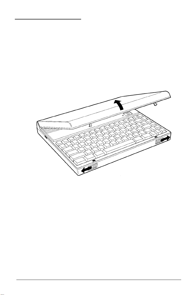
Opening the Screen
Follow these steps to open the LCD screen:
1. Place the computer on a level surface.
2. Turn the computer so its front is facing you.
3. Slide the release latches on the front sides of the computer
toward the sides and lift up the screen.
Setting Up the Computer 1-9
Page 29
Connecting the Trackball
Your computer package includes a trackball, which you connect to
the
EXT KB
You can attach the trackball to the right or left side of your
keyboard or LCD screen; you can also configure it as left- or
right-handed. If you attach it to the right side of your keyboard,
make sure there is not a diskette in the diskette drive. Also, you
will not be able to access the diskette drive while the trackball is
attached. See the trackball manual for instructions on changing its
configuration and attaching it to your computer.
port on the left side of the computer.
Before you can use an optional device like the trackball, you must
install special software, called a device driver. The device driver
allows the operating system and your application software to
recognize the device. The device driver and utilities for the
trackball have already been installed on your hard disk so the
ActionNote will recognize the trackball as soon as you turn it on.
To use the trackball, or any other pointing device attached to the
EXT KB port, you must enable the PS/2 Mouse Support Option
in the ADVANCED CMOS SETUP portion of the Setup program.
This option has been enabled for you, but if you want more
information on the Setup program, see Chapter 5.
1-10 Setting Up the Computer
Page 30
For information on using the trackball, or if you would like to
know more about its device driver and utilities, see the
documentation that came with it.
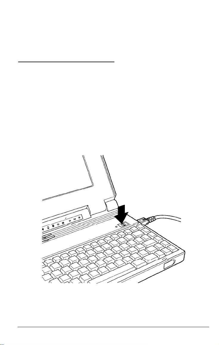
Turning On the Computer
When you first use the ActionNote, the battery may not be
charged; so make sure the AC adapter is connected when you turn
it on for the first time.
Before you turn on the computer, first connect and turn on any
external devices you will be using—such as a printer, monitor, or
pointing device. (See Chapter 4 for information about installing
optional devices.) Then press the power button on the top of the
computer to turn it on.
Setting Up the Computer 1-11
Page 31

The computer displays copyright information and then performs a
series of power-on diagnostics that check the circuit boards,
memory, ports, keyboard, and disk drives. The computer displays
several messages during the diagnostics, including this prompt:
you want to run SETUP
Hit
<DEL>,
If
If the tests indicate a problem with the system or change in
configuration, you will see an error message followed by this
prompt
RUN SETUP UTILITY
Press <F1> to RESUME
If this happens, press F1 to run the Setup program and check your
system configuration. See Chapter 5 for a complete description of
the Setup program.
When the computer completes its testing, it displays a screen
describing the system’s configuration:
If necessary, press the
Pause button on the keyboard to view the
configuration screen. After viewing the screen, press any key to
continue the startup process.
1-12
Setting Up the Computer
Page 32

Because your computer was set up at the factory, the configuration
information should be accurate, If you have changed the
computer’s setup so that this information does not match your
configuration, run the Setup program described in Chapter 5 to
correct it.
Your computer comes with MS-DOS and Microsoft Windows
installed on the hard disk. However, you can use another
operating system, such as OS/2,
®
UNIX,® or XENIX.® Although
this manual includes sample MS-DOS commands, it does not
explain how to use the operating system; see your MS-DOS or
other operating system manuals for complete instructions.
Your computer starts up in MS-DOS and Windows as soon as it
completes the power-on diagnostics. The messages you see as the
computer loads MS-DOS depend on how your computer has been
set up.
If you plan to use another operating system, you need to install it
now. See the documentation that came with your operating system
for installation instructions.
The procedures described in this manual assume you are using
MS-DOS. If you are using another operating system, see your
documentation for instructions on how to perform the various
procedures.
Setting Up the Computer
1-13
Page 33

Chapter 2
Using Your Computer
This chapter describes how to use your ActionNote computer on a
daily basis. It provides information on the following procedures:
Taking care of the computer
Making a backup copy of the VGA utilities
Using the password function
Using the keyboard
Resetting the computer
Turning off the computer
Changing the CPU speed
Using the LCD screen
Using diskettes
Using the hard disk
Using memory.
Using Your Computer
2-1
Page 34

Taking Care of the Computer
Before you begin using your computer, read the following
guidelines to ensure proper maintenance of the ActionNote:
Keep the computer and AC adapter dry, and do not subject
them to extreme heat or cold.
Do not place external devices on top of the computer, even if it
is closed, to prevent damage to the LCD display.
When you are not using the external device connectors, keep
the covers closed to prevent damage to the ports.
Always operate the computer with the battery pack installed.
Occasionally clean the exterior of the computer with a soft,
damp cloth.
Occasionally clean the LCD display using glass cleaner on a
soft cloth; do not apply the cleaner directly to the screen.
2-2 Using Your Computer
Page 35

Backing Up the VGA Utilities
Your computer comes with VGA drivers and utilities already
loaded on the hard disk. To protect these important files, you
should back them up onto a diskette. The files are located in the
\VGAUTILS directory.
Follow these steps to backup your VGA drivers and utilities:
1. Insert a blank, formatted diskette in the diskette drive.
2. Log onto the C:\VGAUTILS directory.
3. Type the following and press
COPY *.* A:
See your MS-DOS documentation for more information about
copying files. For information on using the VGA utilities and
installing the drivers, see Chapter 6.
Enter
Using the Password Function
The ActionNote provides password security for the entire system
or only the Setup program. This allows you to safeguard all your
data or only your Setup configuration. The password function is
optional and you do not have to set a password if you don’t want
to use one.
You use the Setup program to first enable or disable a password
and then define it. (See Chapter 5 for instructions.)
If you enable the power-on password, you must enter it each time
you turn on or reset your computer. (Resetting the computer is
described later in this chapter.) The computer prompts you for the
password after it completes its power-on diagnostics.
Using Your Computer 2-3
Page 36

If you enable the Setup password, you must enter it before you can
use the Setup program. The computer prompts you for the
password after you press
Delete
to start Setup.
Typing the Password
You see this prompt when the password feature is activated:
Enter CURRENT password:
Type the correct password and press
password, the screen does not display the characters you type.
If you do not type the correct password, the screen displays an X
and repeats the password prompt. Try typing the password again.
The computer allows you three tries to enter it correctly. After the
third incorrect attempt, the system displays a blinking face icon
and locks up. You must reset the system to try again.
Enter. To protect your
Note
If you want to change your current password or disable the
password function, you need to use the Setup program. See
Chapter 5 for instructions. If you forget your password, call the
Epson Connection at 1-800-922-8911 for assistance.
2-4
Using Your Computer
Page 37
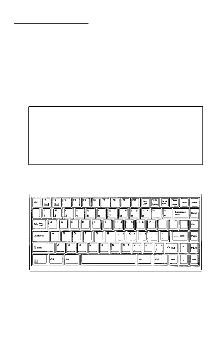
Using the Keyboard
Although the keyboard on the ActionNote has only 84 keys
(85 on the international version), it still provides all the functions
of a full-size (102-key) keyboard. For example, a full-size keyboard
has a separate numeric keypad you can use for both numeric entry
and cursor control. The ActionNote has an embedded numeric
keypad that you access using the
way you use the Shift key to enter uppercase characters. (Using
the embedded numeric keypad is described later in this section.)
Note
The keyboard on the ActionNote is available with different
layouts for different languages. Special keytop sets are available
in some countries. Additionally, you can use MS-DOS to
reassign the layout of your keyboard to duplicate that of
another country. See your MS-DOS manual for more
information.
The following illustration shows the 84-key, US keyboard layout.
Fn
and
Shift
keys in the same
Using Your Computer 2-5
Page 38

This section describes how to use the following features on your
keyboard:
Special keys
The F11 and F12 keys
The embedded numeric keypad.
Special Keys
Certain keys on your keyboard serve special functions when your
computer is running MS-DOS or application programs. The
special keys are described in the following table.
Special key functions
Key
Tab
CapsLock
Shift
Fn
Ctrl
Alt
Purpose
Moves the cursor one tab to the right in normal
mode and one tab to the left in Shift mode.
Changes the letter keys from lower- to uppercase;
changes back to lowercase when pressed again
The number/symbol keys on the top row of the
keyboard and the symbol keys in the main part of
the keyboard are not affected.
Produces uppercase characters or the top symbols
on the keys when used with the main character keys.
Produces lowercase characters when the Caps Lock
function is on. Note: Use this key to reactivate the
system when it is in Suspend mode.
Controls functions on the embedded numeric
keypad as well as other special functions.
Works with other keys to perform special (control)
functions.
Works with other keys to enter alternate character
codes or functions.
2-6 Using Your Computer
Page 39

Special key functions (continued)
Key Purpose
Backspace
Enter
Home End
PgUp PgDn
Esc
F1-F10
F11 F12
NumLock
PrtScr
SysReq
Scroll Lock
Pause
Break
Moves the cursor back one space,
Ends a line of keyboard input or executes a
command.
Control cursor location.
Cancels the current command line or operation.
Perform special functions within application
programs,
Turns on the numeric keypad; changes back when
pressed again.
Prints the screen display on a printer.
Works as defined by an application.
Controls scrolling in some applications.
Suspends the current operation.
Terminates the current operation (when used with
Ctrl).
Insert
Delete
The
NumLock, CapsLock,
Turns the insert function on and off.
Deletes the character marked by the cursor.
and
Scroll Lock
keys work as toggles;
press them once to turn on the function and again to turn it off.
When the function is on, the corresponding LED above the
keyboard is lit.
Using Your Computer 2-7
Page 40
Using F11 and F12
The F11
application programs. You activate these keys by using Fn with
the
hold down
Using
the
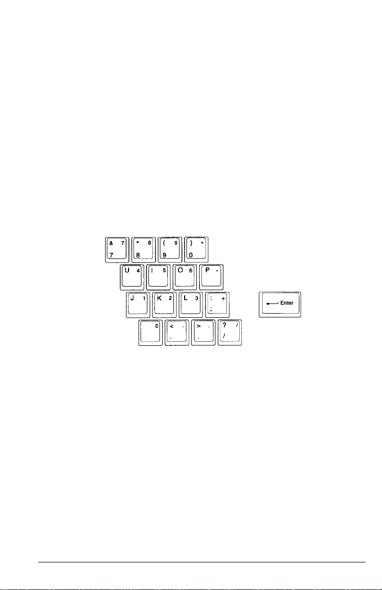
The embedded numeric keypad allows you to enter numeric
characters from the keyboard when the Num Lock function is on.
You can also use the keypad to control the cursor. The embedded
numeric keypad is shown below:
and
F12
keys perform special functions within
F1 and F2 keys. Hold down Fn and press F1 to produce F11;
Fn and press F2 to produce F12.
Embedded Numeric Keypad
NumLock to turn Num Lock (and its LED) on and off. Then
Press
press the key to enter the numeric character printed on the
right-hand side of the key top. Press
the cursor. You can press
character on the key; press
alphabetic character in uppercase.
When Num Lock is off, you can generate the numeric character by
pressing
pressing
Fn Shift plus the key. You can move the cursor by
Fn
plus the keys.
Fn
plus the key to enter the alphabetic
Fn Shift
Shift plus the keys to control
plus the key to enter the
2-8 Using Your Computer
Page 41

The following table summarizes how to use the embedded
numeric keypad.
Embedded keypad functions
Embedded numeric keys
Keys pressed by themselves numeric alphabetic
Keys pressed with Shift
Keys pressed with Fn
Keys pressed with Shift and Fn
NumLock on
cursor control
alphabetic cursor control
upper case
alphabetic
Resetting the Computer
If necessary, you can clear the computer’s current settings or its
memory without turning it off; you do this by resetting it. For
example, if an error occurs and the computer does not respond
your keyboard entries, you can reset it to reload the operating
system and try again.
Caution
Resetting the computer erases any data in memory you have
not saved, so do not use the reset function unless necessary.
Also, some programs classify and store new data when you exit
them properly; so do not reset the computer before you exit a
program, if possible.
NumLock off
upper case
alphabetic
numeric
to
Using Your Computer 2-9
Page 42

To reset the computer, the operating system must be either on the
hard disk or on a diskette in drive A. If you are using MS-DOS,
hold down Ctrl and
for a moment and then the computer reloads MS-DOS.
If resetting the computer does not correct the problem, you
probably need to turn it off and back on again.
Alt
and press
Delete.
The screen goes blank
Turning Off the Computer
Before turning off the computer, save your data and leave the
application program you are using. Make sure the hard disk drive
and the diskette drive lights are off, then turn off the computer by
pressing the power button on top of the computer.
Caution
Always make sure the computer is off when you connector
disconnect equipment, such as a printer or the trackball.
Changing the CPU Speed
Your computer's processor can operate at two speeds: high or low
MHz). At high speed, the computer performs all tasks faster.
(8
You may need to select low speed, however, to run some
copy-protected programs or a program that has a specific timing
requirement. You can also use low speed to reduce power
consumption.
Whenever you turn on or reset the computer, it starts up in high
speed. To change the speed, you must turn on the Num Lock
feature.
2-10 Using Your Computer
Page 43

If necessary, press
Then, to change to low speed, press
high speed, make sure Num Lock is on, and press Ctrl Alt +.
NumLock
to turn Num Lock (and its LED) on.
Ctrl Alt –.
To change back to
Note
You must press – or + on the embedded numeric keypad only.
Using the LCD Screen
The screen on your ActionNote is a backlit monochrome LCD. You
can adjust the brightness and contrast with the two controls on the
top left side of the computer. Adjust the switches to produce the
best display for your viewing angle.
Slide the brightness switch to the right to lighten the brightness,
and to the left to darken the brightness. Slide the contrast switch to
the right to increase the contrast, and to the left to decrease the
contrast.
Using Diskettes
Be sure to purchase high-quality diskettes to ensure reliability. For
the 3½-inch, 1.44MB diskette drive in your ActionNote, you can
use either of the following types of diskettes:
720KB, double-sided, double-density (usually labelled 2DD)
1.44MB, double-sided, high-density (labelled 2HD).
Using Your Computer 2-11
Page 44

Inserting and Removing Diskettes
To insert a diskette, hold it with the label facing up and the metal
shutter leading into the drive, Slide it into the drive until it clicks
into place.
When you want to remove the diskette, make sure the drive light
is off, then press the release button. When the diskette pops out,
remove it and store it properly.
2-12
Caution
Never remove a diskette or reset or turn off the computer while
the drive light is on. You could lose data. Also, be sure to
remove all diskettes before you turn off the computer.
Using Your Computer
Page 45

Write-protecting Diskettes
You can write-protect a diskette to prevent its data from being
altered. When a diskette is write-protected, you can read it and
copy data from it, but you cannot store new data on it or delete
any files it contains. If you try to change data stored on a
write-protected diskette, you see an error message.
To write-protect a 3½-inch diskette, turn the diskette over so you
are looking at the underside. Slide the switch in the lower left
comer toward the edge of the diskette until it clicks into position,
exposing a hole.
To remove the write protection, slide the switch toward the center
of the diskette until the hole is covered.
Using Your Computer
2-13
Page 46

Making Backup Copies
It is important to make copies of all your data and system
diskettes. Make backup (working) copies of all diskettes that
contain programs, such as your MS-DOS and Windows diskettes;
then use only the copies. Store the original diskettes away from
your working diskettes. Also, copy your data diskettes as
necessary to keep your files up-to-date.
You’ll probably use your hard disk to store the programs and data
files you use regularly. Keep backup copies of all your files on
diskettes. For large amounts of data, you might want to consider a
portable tape backup unit.
You can copy your data in several ways. See your MS-DOS or
other operating system manual for instructions.
Using a Single Diskette Drive System
MS-DOS expects a computer to have at least two diskette drives (A
and B), and displays prompts and messages accordingly. Your
ActionNote has one 3½-inch diskette drive; this is drive A.
MS-DOS uses the one drive as two by displaying alternate
prompts for the source and target diskettes.
For example, if you need to make a copy of a diskette, you can
insert the diskette in drive A and enter the following command:
DISKCOPY A : B :
MS-DOS copies the data from drive A (the source diskette) to its
memory and then prompts you to insert the diskette for drive B.
At this point, you remove the original diskette, insert a blank
diskette (the target diskette), and press any key to continue. Then
the operating system copies the data from its memory to the
second diskette.
2-14 Using Your Computer
Page 47

When you swap diskettes this way, it is a good idea to
write-protect the original diskette so you don’t accidentally write
over it. (See “Write-protecting Diskettes” earlier in this chapter for
more information.)
Using a Hard Disk
The hard disk installed in the ActionNote has been prepared for
use at the factory and has MS-DOS and Windows installed. If you
plan to use MS-DOS or Windows, you can install your application
programs and begin work. See the documentation that came with
your programs for instructions.
Follow these precautions to protect your hard disk from damage
and to avoid losing data:
Never turn off or reset the computer when the hard disk drive
light is on. This light indicates that the computer is copying
data to or from the hard disk.
Do not move the computer when the power is on. After
turning the power off, wait 20 seconds before moving it. This
allows the disks in the drive to stop spinning and the hard
disk read/write heads to lock in place so you do not damage
the drive.
Backing Up the Hard Disk
Although the hard disk is very reliable, be sure to backup your
files in case you lose some data accidentally. Also, make copies of
all your system and application program diskettes before copying
the programs to the hard disk. See your operating system manual
for instructions.
Using Your Computer
2-15
Page 48
Using Memory
Your computer comes with 4MB or 8MB of memory, and you may
have installed an optional expansion memory module to increase
the total amount. This section describes how the memory in your
computer works. Also be sure to see your MS-DOS manual for
complete information on memory management.
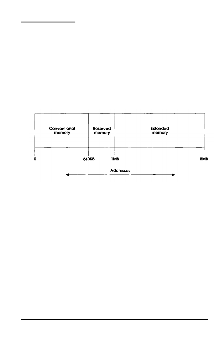
A computer’s memory is divided into three types: conventional,
reserved, and extended. The following diagram shows the
relationships between these types of memory and their addresses.
All memory in a computer is managed using addresses—numbers
that describe the location of each byte of data. Each memory chip
must have its own set of unique addresses so that the operating
system knows where to store and find data.
Conventional memoy is memory that MS-DOS recognizes and
manages directly. The size of conventional memory is limited to
640KB and has addresses in the range 0 to 640KB.
Reserved memory is memory in the range 640KB to lMB. The
system enhances its performance by using 128KB of this memory
as shadow RAM, and the remaining memory is available.
2-16 Using Your Computer
Page 49

Extended memory is memory with addresses in the range lMB to
8MB, and is used only by the following:
Certain operating systems, such as OS/2
Some MS-DOS interfaces, such as Windows
Some RAM disk programs, such as VDISK
Some hard disk caching programs, such as SMARTDRV
Certain specially-written MS-DOS applications.
Use of extended memory requires a memory manager. Most
versions of MS-DOS include a standard extended memory
manager. If you are using MS-DOS, Windows, and other
compatible programs, it is best to use one of the memory managers
(such as HIMEM.SYS) that came with your software because these
memory managers have been tested and proven reliable.
Most MS-DOS commands and application programs cannot use
extended memory directly. They need to use expanded memory,
which uses a portion of reserved memory as a window to access
RAM beyond lMB. This type of memory allows some MS-DOS
applications to get around the 640KB size limitation. You control
expanded memory with a memory manager (such as
EMM386.EXE), which enables the computer to use extended
memory as expanded memory.
Using Your Computer
2-17
Page 50

Chapter 3
Powering the Computer
You can operate your ActionNote using the AC adapter, optional
automobile adapter, or the removable battery pack. This chapter
describes how to use these power sources, and how to best
conserve energy when using the battery pack.
Using the AC Adapter
To conserve the battery, use the AC adapter whenever you have
access to an electrical outlet. When the computer runs on the AC
adapter, it draws power from the adapter instead of using the
battery. Whenever the AC adapter is connected, it recharges the
battery pack.
The AC adapter is ideally suited for travel to foreign countries. It is
designed to operate in 100 to 240 VAC ranges with a frequency of
50 to 60 Hz. All you need is an appropriate plug for the electrical
socket; see Appendix C for specifications.
See Chapter 1 for instructions on how to connect the AC adapter to
the computer.
Powering the Computer
3-1
Page 51

Using the Battery Pack
The removable NiCad battery pack powers the computer when the
AC adapter is not connected. The length of time the battery can
provide power depends on how you use the ActionNote. If you
operate the computer using a bright screen display and access the
hard disk often, you will consume more battery power and
shorten the length of the charge.
To increase the amount of time you can use the computer without
electrical power, you can purchase additional battery packs. Each
battery pack comes with a carrying case to protect it when not in
use. Maintaining a supply of charged battery packs allows you to
replace a low battery and continue your work.
Note
Use only the battery pack designed for use with the ActionNote
(A880451).
Replacing the Battery Pack
Follow these steps to install the battery pack:
1. Turn off the computer.
2. If the AC adapter is connected, disconnect it.
3. Turn the computer upside down with the back facing you.
3-2 Powering the Computer
Page 52
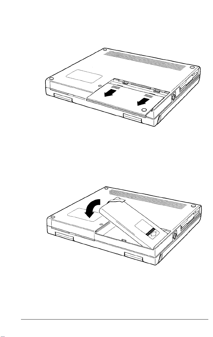
4. Press down on the release buttons on the battery compartment
cover and slide the cover toward you.
5. Pull up on the cloth tab and lift out the low battery.
6. Remove the fully charged battery pack from its carrying case
and slide it into the slot. Insert the right side (with contacts)
first, then press on the left side to secure the battery.
Powering the Computer 3-3
Page 53

7. Slide the battery cover back into place making sure the tabs on
the cover fit into the slots on the computer’s cover. Press the
cover from the back side until it snaps closed.
Note
When you replace the battery pack, make sure the new
battery is fully charged; otherwise you’ll need to recharge it
before you can use it.
8. Turn the computer right side up.
3-4 Powering the Computer
Page 54

Recharging the Battery
The battery pack that comes with your ActionNote is rechargeable.
You may need to charge the battery pack before using it for the
first time, and you must charge it when it runs low on power.
Your computer warns you when the battery is low through the
low battery light.
To charge the battery pack, leave it in the computer. Connect the
AC adapter to the computer and to an electrical outlet. As an
alternative, you can connect the optional automobile adapter to
the cigarette lighter in your car. The computer charges the battery
whenever the adapter is attached.
The charging light blinks while the battery is charging. When the
battery is completely charged, the light stays on.
The computer takes approximately 3½ hours to charge a
completely discharged battery pack. If you use the system while
the battery is recharging, it can take up to 6 hours. If the battery
still has some charge left when you start charging, the time will be
less.
If you have additional battery packs, it is a good idea to keep them
fully charged so you can use them to replace the battery pack in
your computer when it runs low. This is especially useful if you
are travelling and will need to run the computer off the battery; an
extra battery pack or two extends the length of time you can
power the computer without the AC adapter.
Rechargeable batteries like the one supplied with your ActionNote
have a charge “memory.”
battery before it runs out completely, it starts to “remember” this
discharge level. When you use it again, it may stop supplying
power at the same level.
If you frequently start to recharge the
Powering the Computer 3-5
Page 55

To reduce the memory effect and extend the life of your battery,
you should let it discharge completely whenever possible before
recharging it. If you use the computer every day, you should
completely discharge the battery at least once a week.
If you find that over time the battery is losing its charge sooner,
the life of the battery may be reaching its end. Try letting the
battery discharge completely; then recharge it. If this fails, replace
it with a new battery pack.
Note
When your battery can no longer be recharged, please contact
your local government agency responsible for hazardous waste
disposal. NiCad batteries are considered hazardous waste and
should be recycled or disposed of properly.
Low Battery Indicator
When the battery’s power is getting low, the low battery light
starts flashing and the computer starts beeping. At this point,
replace it with a fully charged battery or connect the AC adapter.
You need to recharge the battery (as described above) before you
can use it again to power the computer without the AC adapter.
If your AC adapter is not available, follow these steps:
1. Complete your current activity.
2. Save your data.
3. Exit the program you are using.
4. Turn off the computer.
3-6 Powering the Computer
Page 56
Once your computer starts beeping, you have approximately two
minutes to save your data. If the batteries run out suddenly, you
will lose any data you have not saved.
Turn off the computer before replacing the battery pack.
Otherwise, you will lose data, and you may even damage the
computer.
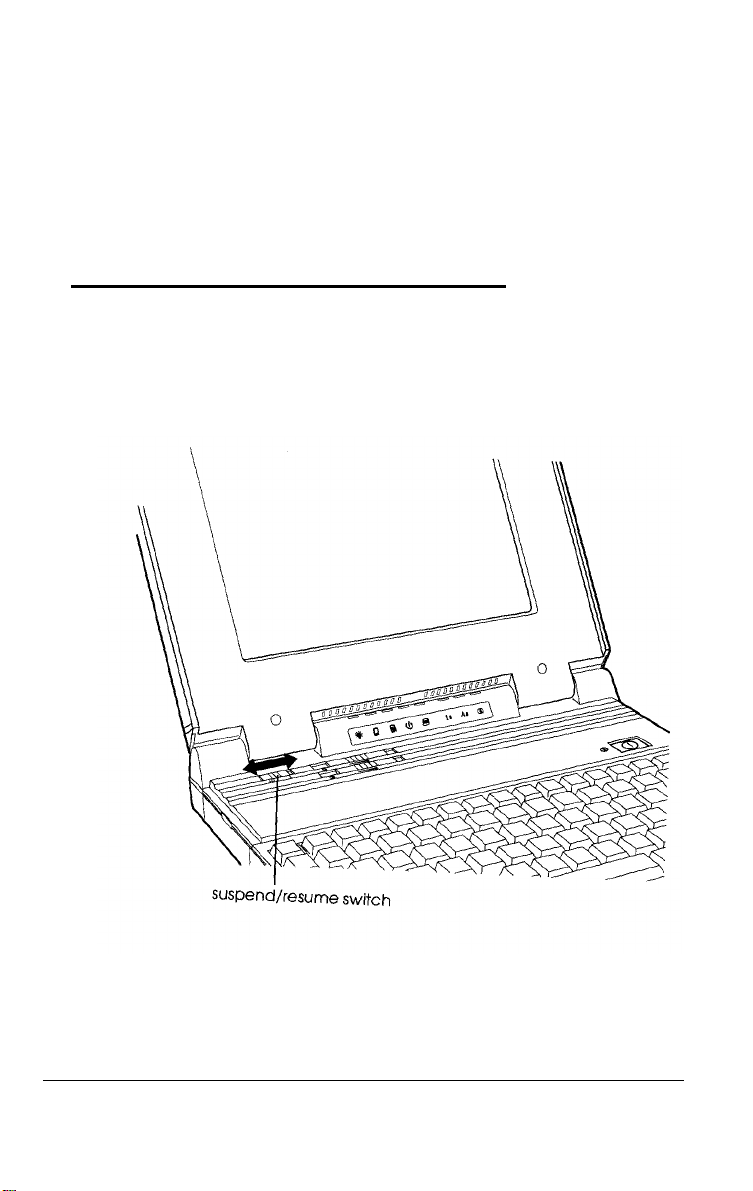
Using the Suspend/Resume Switch
The suspend/resume switch provides an efficient way to save
battery power. This switch is located on the top left side of the
computer.
Powering the Computer 3-7
Page 57

Slide the suspend/resume switch to the right to temporarily stop
system activity when you do not need to use your computer for
short periods of time. The screen goes dark and the computer
suspends power to its components and devices; it continues to
supply power to the RAM. (If you are not going to use the
computer for a longer time—20 minutes or more, for
example—turn it off.)
To resume activity, slide the switch to the left or press the
key. The computer resumes normal operation at the point at which
you suspended it.
Using Setup to Conserve Battery Power
The Setup program includes power management options that
enable you to conserve battery power. These options allow you to
control various functions of the computer so you don’t waste
power on devices you are not using.
The power management options are available from the
ADVANCED CHIPSET SETUP portion of the Setup program. You
can specify timeout periods for the LCD display, the hard disk
drive, and/or the system. For a complete description of these
options and the Setup program, see Chapter 5.
Shift
3-8 Powering the Computer
Page 58

Chapter 4
Connecting Optional Devices
This chapter describes how to connect the following optional
devices to your ActionNote:
External monitor
Parallel printer or other device
Serial device
Trackball, mouse, or other pointing device, or an external
keyboard
Internal fax/modem
Expansion memory modules
Numeric coprocessor.
Make sure the computer is turned off before you install or connect
any of these devices. This is a safety precaution and is also
necessary for the computer to recognize that you connected a new
device.
Connecting Optional Devices 4-1
Page 59

The interfaces for the
on the back of the computer. The interfaces for the
and
EXT KB
access any of these ports, open the port cover by pulling down on
the notch at the top.
ports are located on the left side of the computer. To
VIDEO, PRINTER,
and COM 1 ports are located
COM
Connecting an External Monitor
The
VIDEO
external color or monochrome VGA monitor. When a monitor is
connected, you can display text and graphics on both the LCD
screen and the monitor. You can also display higher-resolution
video modes on the external monitor.
port on your computer allows you to connect an
2, LINE,
Follow these steps to connect a monitor
1. Make sure both the computer and the monitor are turned off.
4-2 Connecting Optional Devices
Page 60

2. Connect the monitor cable to the port labelled VIDEO on the back
of the computer.
3. If the connector has retaining screws, tighten them by hand or
with a screwdriver.
4. Connect the other end of the cable to the monitor, if it is not
already attached.
5. Connect the monitor’s power cable to a grounded (earthed)
electrical socket.
See Chapter 6 for details on using the VGACONF utility, which
allows you to change the display characteristics of your LCD
and/or external monitor.
Connecting Optional Devices 4-3
Page 61

Connecting a Parallel Printer
You can use the
a Centronics®-compatible printer. Before connecting a printer,
check the manual that came with it to see if you need to change
any of its settings.
You can also connect some third-party external diskette drives to
this port. Check with the Epson Connection for product
compatibility requirements. If you do connect an external diskette
drive to this port, be sure to run the Setup program to identify the
drive.
Follow these steps to connect a parallel device:
1. Place the printer or other device in a convenient location near
your computer, so that the power and data cables will not
interfere with the paper or paper trays.
2. Make sure both the computer and printer are turned off.
3. Connect the printer cable to the
PRINTER
port to connect a parallel device, such as
PRINTER port.
4-4 Connecting Optional Devices
Page 62

4. If the connector has retaining screws, tighten them by hand or
with a screwdriver.
5. Connect the other end of the cable to the printer. If the printer
interface has retaining clips, squeeze them gently until they
snap into place.
6. Connect the printer’s power cable to a grounded (earthed)
electrical socket.
Connecting a Serial Device
You can use the
devices, such as a serial printer or plotter. You could also connect a
modem or pointing device, such as a trackball or mouse.
COM 1
and/or COM 2 port to connect serial
Note
You cannot use the
installed.
Follow these steps to connect a serial device:
1. Make sure both computer and the serial device are off.
COM 2
port if the internal fax/modem is
Connecting Optional Devices 4-5
Page 63

2. Connect the serial cable to the COM 1 or COM 2 port.
3. If the connector has retaining screws, tighten them by hand
or with a screwdriver.
4. Connect the other end of the cable to the serial device. If the
connector has retaining screws, tighten them.
5. Connect the serial device’s power cable (if it has one) to a
grounded (earthed) electrical socket.
Check the documentation that came with your serial device to see
if any other steps are necessary.
4-6 Connecting Optional Devices
Page 64

Checking the Serial Port Settings
The
COM 1
data at a variety of speeds and with many different protocols. This
means you need to configure the port to match the signals of the
serial device. As a general rule, choose the highest speed (baud
rate) and the protocol that provides the best error detection.
Check the documentation that came with your serial device to see
if you need to adjust any of its settings.
and
COM 2
ports are capable of sending and receiving
Note
If your application program cannot send printer output directly
to the serial port, you can use the MS-DOS MODE command to
redirect the output. You can even tell the computer to redirect
printer and serial port settings automatically if you place the
appropriate MODE commands in your AUTOEXEC.BAT file,
See your MS-DOS manual for instructions.
Using the EXT KB Port
You can use the
PS/2-compatible pointing device. See Chapter 1 for detailed
instructions.
You can also connect the mouse/keyboard adapter to this port. If
you use the adapter, you can connect both a pointing device and
an external keyboard at the same time. You can connect a
PS/2-compatible keyboard to this adapter, but it does not support
®
-type keyboards.
AT
EXT KB
port to connect the trackball or any
Connecting Optional Devices 4-7
Page 65

Connecting An Optional Pointing Device
You can connect a PS/2-type mouse or other pointing device to
the
EXT KB
other pointing device with your applications, you need to install
the special software driver that came with it. See the
documentation supplied with the device for instructions.
port as shown below, Before you can use the mouse or
Also, before using a pointing device attached to the
you must enable the PS/2 Mouse Support Option in the
ADVANCED CMOS SETUP portion of the Setup program. See
Chapter 5 for details on using the Setup program.
Connecting an External Keyboard
If you are typing for extended periods of time, you may want to
connect an external keyboard. You must first connect the
mouse/keyboard adapter to the
Then connect the keyboard to the adapter.
4-8 Connecting Optional Devices
EXT KB
port on the computer.
EXT KB
port,
Page 66
Connecting the Internal Fax/Modem
If the internal fax/modem is installed in your ActionNote
computer, you can connect it directly to your telephone line using
a standard phone jack. The modem will then be ready to use.
Note
If your computer did not come with the internal fax/modem
installed, you must have an Authorized Epson Servicer install it.
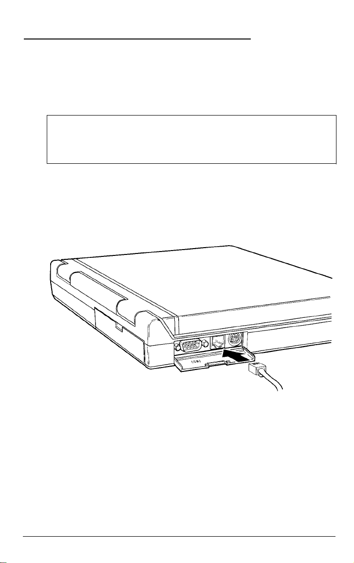
If you purchased a fax/modem with your computer, a telephone
cable is included in your package. Insert one end of the modular
jack cable into the
insert the other end into a modular jack outlet.
LINE
port on the left side of the computer and
If you have a fax/modem, your package also includes BitCom data
communications software and WinFax LITE fax transmission
software already loaded on your hard disk drive. See the
documentation that came with these applications for details on
how to use them.
Connecting Optional Devices
4-9
Page 67

Appendix B provides a summary of the modem’s features and
internal command set. You need to use the fax/modem’s built-in
set of commands only if you are not using the telecommunications
software package. Each communications program provides its
own set of commands that you will use to control the modem
instead of the built-in set.
Note
Be sure to read the modem FCC information at the front of this
manual to avoid electrical interference problems.
Adding Memory Modules or a Numeric
Coprocessor
The sections below describe how to add memory to your computer
and install a numeric coprocessor. To access the sockets for these
options, you need to remove the keyboard.
Caution
It is best to have your Authorized Epson Servicer install the
memory module or a numeric coprocessor for you because they
can be damaged easily if installed incorrectly. If you prefer to
install them yourself, carefully follow all the instructions in this
section. If you have any questions at all, please contact your
Authorized Epson Servicer or call the Epson Connection.
4-10 Connecting Optional Devices
Page 68
Removing the Keyboard
To remove the keyboard, follow these steps:
1. Make sure the computer is turned off.
2. Disconnect all cables from the ports and connectors on both the
sides and back of the computer. (Unplug the AC adapter from
its wall outlet, if necessary.)
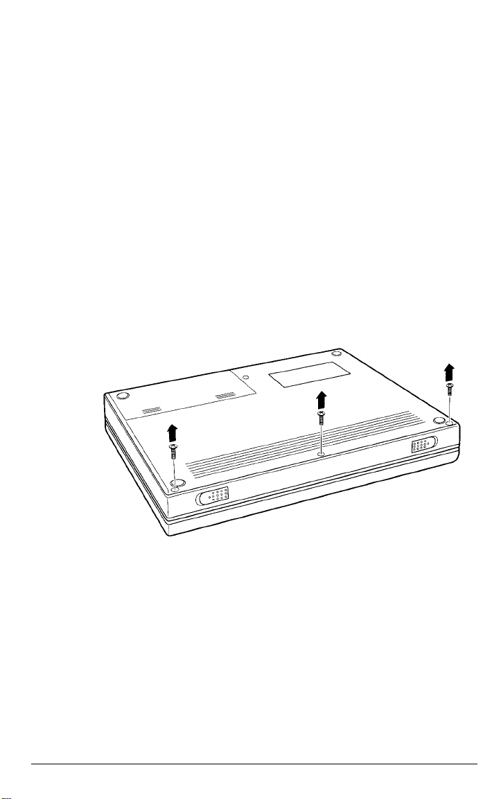
3. Turn the computer upside down with the front facing you.
4. Remove the battery pack (as described in Chapter 3).
5. Remove the three screws on the front edge of the computer's
case.
6. Turn the computer right side up.
7. Open the top cover.
Connecting Optional Devices
4-11
Page 69
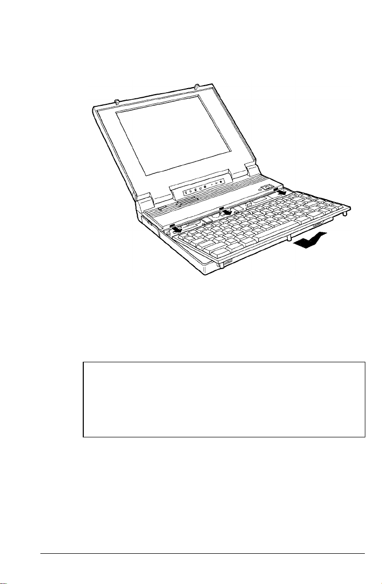
8. Carefully detach the keyboard by lifting upon the front and
sides of the keyboard. Then pull it toward you.
9. Turn the keyboard upside down by tilting the front of the
keyboard up and back toward the LCD. Carefully set the
keyboard on top of the computer. Be careful not to strain or
twist the keyboard cables.
WARNING
Be sure to ground yourself every time you remove the
keyboard, If you are not properly grounded, you could
generate an electric shock that could damage one of the
computer’s components when you touch it.
4-12 Connecting Optional Devices
Page 70
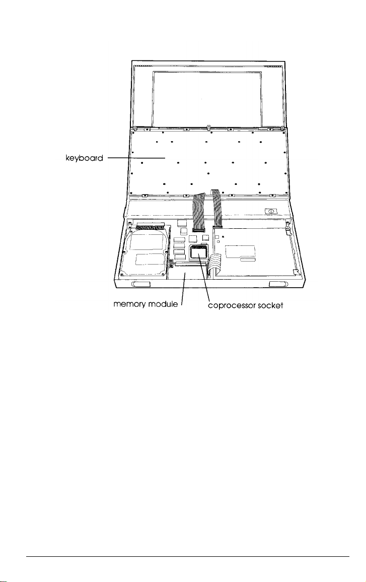
Installing a Memory Module
Your computer comes with 4MB or 8MB of memory. Two MB are
soldered directly onto the system board, and a 2MB (or 6MB)
memory module is installed in the computer (as shown above).
You can increase your memory to 8MB by replacing the 2MB
memory module with a 6MB module.
Connecting Optional Devices
4-13
Page 71
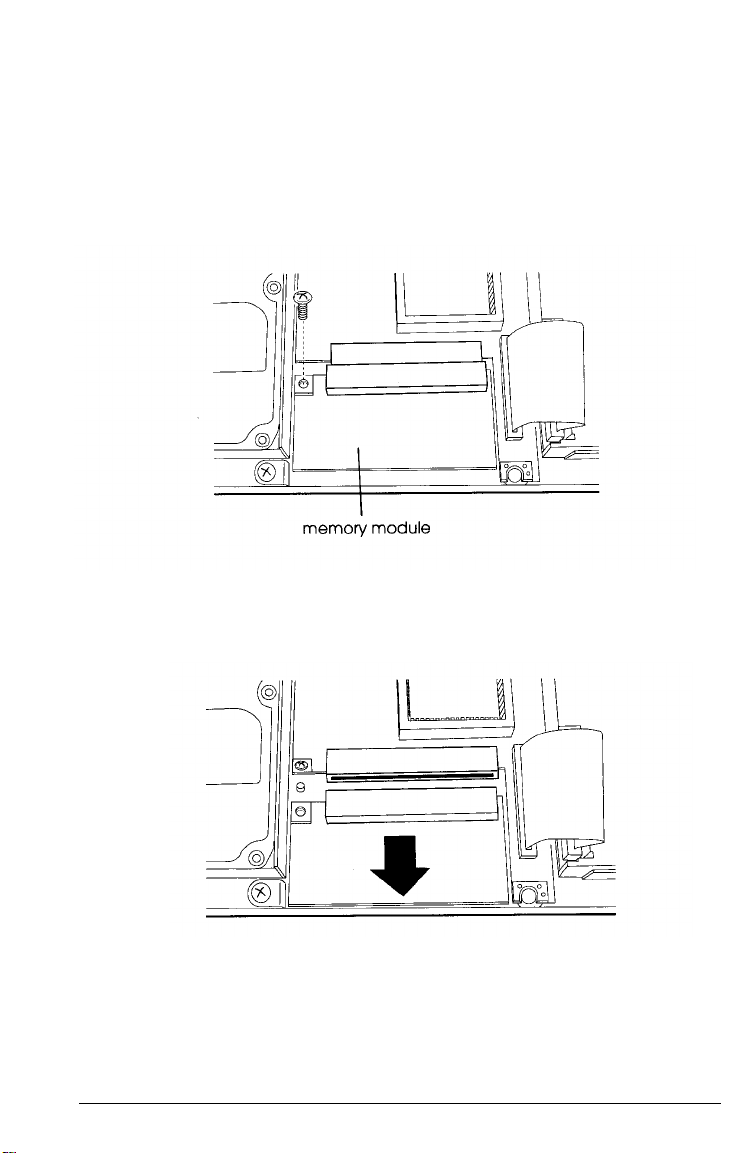
Follow these steps to install a memory module:
1. Remove the keyboard as described above.
2. Remove the screw
system board.
3. Gently disconnect the memory module from its socket by
sliding the module toward the front of the computer.
that attaches the 2MB memory module to the
4-14 Connecting Optional Devices
Page 72
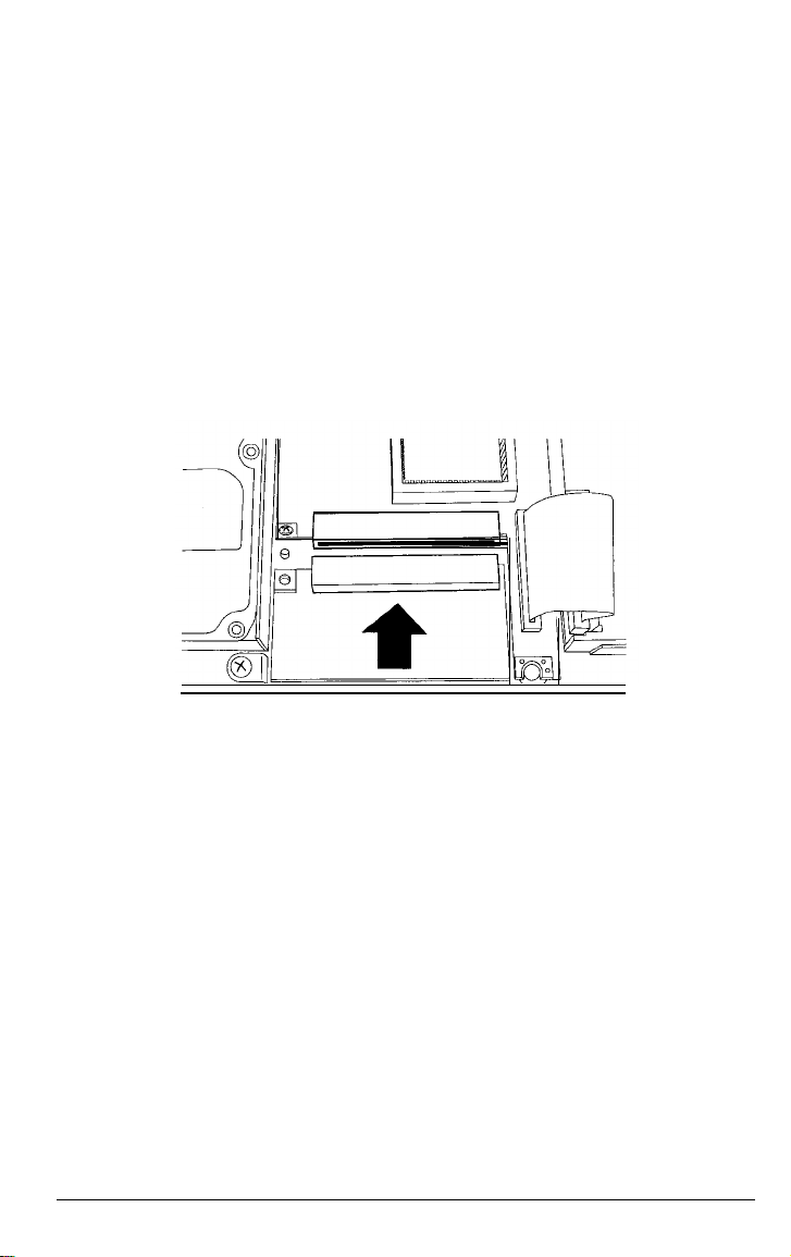
4. Lift the memory module out of the computer.
5. Lower the new memory module straight down into the
computer until its connector aligns with the socket on the
system board. Make sure the hole for the attachment screw is
on your left.
6. Carefully press the module straight into the socket. The
connector and socket are designed so they fit together only if
you have aligned them correctly; so do not force them. If you
have trouble, remove the module and try again.
7. When the connector is firmly attached to the socket, replace the
screw on the left side of the module.
8. Replace the keyboard as described on page 4-18.
Connecting Optional Devices
4-15
Page 73

After you reassemble your computer, you need to run the Setup
program to make sure it recognizes the new memory amount. As
soon as you turn on the computer, it will prompt you to run Setup
because of the memory mismatch. See Chapter 5 for instructions.
If you later remove a memory module, be sure to run the Setup
program again.
Installing a Numeric Coprocessor
Your computer has a socket for a numeric (math) coprocessor,
which can be used for the Cyrix 83S87-25 coprocessor. Installing a
numeric coprocessor speeds up your computer’s numeric
calculations and graphic displays when you are using certain
application software. Contact the Epson Connection or your sales
representative for additional information on choosing a numeric
coprocessor compatible with the Cyrix 486SLC2-50 CPU.
The coprocessor chip can be easily damaged and is expensive to
replace; so if you don’t feel confident about installing it yourself,
ask your Authorized Epson Servicer for assistance.
To install the coprocessor, follow these steps:
1. Remove the keyboard as described on page 4-11.
Caution
Make sure you ground yourself before you touch the
coprocessor chip. Then remain as stationary as possible
while you install it. Do not touch the pins on the chip;
handle the coprocessor only by the edges of its case.
4-16 Connecting Optional Devices
Page 74

2. Place the coprocessor over the socket so that the round
indentation indicating pin 1 is in the upper left corner. Then
push it down into the socket.
3. Replace the keyboard as described in the next section.
The computer automatically detects when’s coprocessor is
installed. When you turn on the computer, the system
configuration screen shows that a numeric coprocessor is present.
Caution
If you need to remove the math coprocessor, do not try to do it
yourself. This procedure requires a special extraction tool.
Contact your Authorized Epson Servicer.
Connecting Optional Devices 4-17
Page 75

Replacing the Keyboard
After installing a memory module or numeric coprocessor, you
must replace the keyboard. Follow these steps:
1.
Carefully lift the keyboard off the top of the computer, turn
it right side up, and align it over the front of the computer.
Make sure the keyboard cables are not twisted.
2.
Carefully press the keyboard forward until the tabs on the
keyboard fit into the slots on the computer’s cover.
3.
Press down on the front of the keyboard until it is securely in
place.
4-18 Connecting Optional Devices
Page 76

4. Turn the computer upside down with the front facing you and
replace the three screws on the front side of the cover.
5. Replace the battery pack.
6. Turn the computer right side up.
7. Connect any optional devices that you may have installed
previously.
Connecting Optional Devices
4-19
Page 77

Chapter 5
Running Setup
The Setup program defines your system’s configuration so
the computer uses all of its devices properly. Because your
computer was set up at the factory, the configuration information
is accurate when you first setup the computer. If you change the
computer’s configuration by adding optional devices, however,
you need to run the Setup program to update the system.
The Setup program is stored in the computer’s ROM BIOS
(read-only memory, basic input/output system), so you can run
the program any time you turn on or reset the computer. Setup lets
you verify or change the following settings:
Standard CMOS settings, such as the current date and time
and drive types
Advanced CMOS settings, such as typematic rates, startup
functions, and password checking
Advanced chipset settings, such as power management
functions.
The configuration you define through the Setup program is stored
in a special area of memory called CMOS RAM. This memory is
backed up by a battery, so it is not erased when you turn off or
reset the computer. Whenever you start the computer it checks the
settings, and if it discovers a difference between the information in
CMOS RAM and your system’s configuration, it prompts you to
run Setup. You see a message such as the following:
CMOS display type mismatch
RUN SETUP UTILITY
Press <F1> to RESUME
If this happens, press F1 to run Setup and correct the setting.
Running Setup 5-1
Page 78

Starting the Setup Program
To start the Setup program, you must turn on or reset the
computer. During the memory test, press
program.
If you have already enabled the Password function for the Setup
program, you will be prompted to enter it now.
You see the first menu screen:
Delete to start the Setup
Press or to move from one menu item to the next. The
screen displays a brief description of the highlighted menu item.
When the-correct procedure is highlighted, press
operation.
Enter to start the
5-2 Running Setup
Page 79

When you select one of the SETUP options, you see this screen:
Press any key to continue, or press E
SC to exit the Setup program.
Changing the Settings
At the bottom of each Setup screen, you see a list of the keys you
can use to select options on that screen. Their functions are
described in the following table. (Each screen lists the keys
available; use only the keys listed for that screen.)
Setup function keys
Key(s)
Esc
PgUp or PgDn
Function
Cancels the current screen and returns to the
previous menu
Move between options on the screen
Change the value of an option on a SETUP
screen
Running Setup 5-3
Page 80

Setup function keys
Key(s)
F1
F2 or F3
F5
F6
F10
Function
Displays help information about the option
currently selected
Reverses the color of the screen
Automatically changes all settings to their
original values before changes were made
Automatically changes all settings to their BIOS
default values
Save the current values and exit
Automatically Configuring Your System
You can use the AUTO CONFIGURATION WITH BIOS DEFAULTS
option to automatically configure your system to the factory
default settings. When you select this option, the program asks
you to confirm that you want to load the defaults.
Saving Your Selections
The changes you make in the Setup program are temporary until
you save them. This is important to remember in case you change
any settings by mistake and want to return to your previous
settings.
Whenever you want to save your new settings, select the
WRITE TO CMOS AND EXIT option. The program asks you to
confirm that you want to save the new settings and exit. Press
and
Enter.
The system restarts with the new configuration
settings.
5-4 Running Setup
Y
Page 81
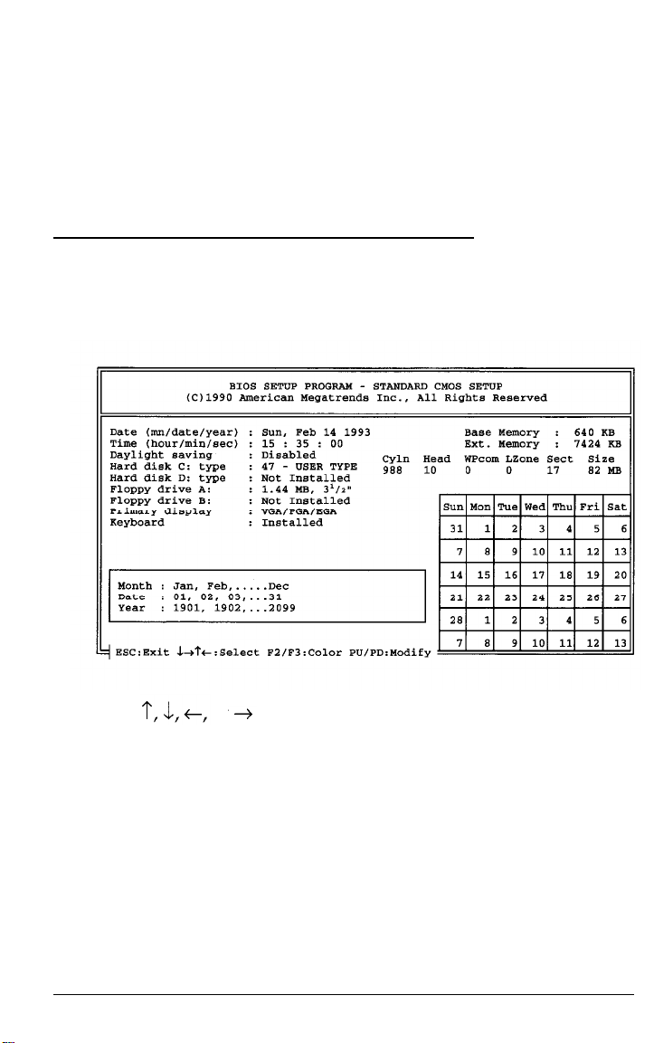
You can also exit the Setup program without saving the new
selections to CMOS RAM. Select the DO NOT WRITE TO CMOS AND
EXIT option. The program asks you if you want to quit without
saving the current settings. Press Y and
with the previous configuration settings.
Enter.
The system restarts
Changing the Standard CMOS Setup
When you select the STANDARD CMOS SETUP option from the
main menu, you see this screen:
Press or to move to the option you want to change.
The Setup program displays information about each option as you
highlight it. Use
Press ESC to return to the main menu.
PgUp
or
PgDn
to
change the value of an option.
Running Setup 5-5
Page 82

The options on the STANDARD CMOS SETUP screen are
described in the following table. Note that the Setup program
displays the possible settings for each option at the bottom of the
screen when the option is highlighted.
STANDARD CMOS SETUP options
Option
Date
Time
Daylight saving Enables or disables daylight savings
Hard disk C: type Identifies the hard disk drive installed in the
Hard disk D: type Always set to Not Installed
Floppy drive A:
Floppy drive B:
Primary display Identifies the LCD display
Keyboard
Function
Sets the current system date in mm/dd/yy format
Sets the current system time
computer; this setting is accurate for the
factory-installed hard disk; do not change it
Identifies the diskette drive, which is 1.44MB,
3½ inch; do not change this setting
Set to Not Installed (unless you install an optional
external diskette drive)
Tells the system whether or not to test the
keyboard during system setup
5-6 Running Setup
Page 83
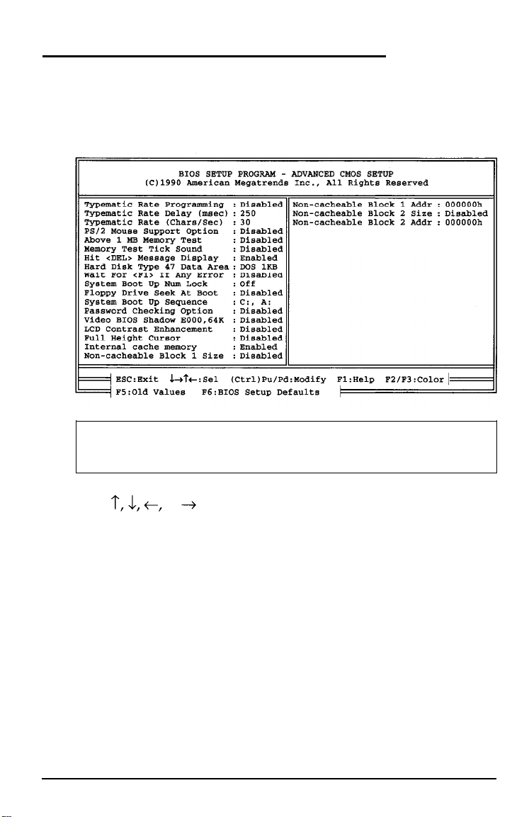
Changing the Advanced CMOS Setup
when you select the ADVANCED CMOS SETUP option from the
main menu, you see this screen:
Note
This screen shows the BIOS default settings.
Press or to select the option you want to change. When
an option is highlighted, you can press F1 to display information
about the option, including the possible settings. Use
PgUp or
PgDn to change the value of an option. Press Esc to return to the
main menu.
The options on the ADVANCED CMOS SETUP screen are
described in the following table. If you want help with a particular
option, move the highlight to the option and press
F1.
Running Setup 5-7
Page 84

ADVANCED CMOS SETUP options
Option
Typematic Rate
Programming
Typematic Rate
Delay
Typematic Rate
PS/2 Mouse
Support Option
Above 1 MB
Memory Test
Memory Test Enables or disables an audible ticking sound as
Tick Sound memory is tested during system startup
Hit <Del>
Message Display
Function
Enables or disables programming of the typematic
rate; if enabled, you can change the next two options
on the screen
Sets the delay period between the time you press a
key and the time the character appears on the screen
(in milliseconds); the higher the number, the longer the
delay; the default is 500 msec, or 1/2 second
Sets the rate at which a character repeats when you
hold down a key; the higher the number, the faster the
repeat rate; the default is 24 characters per second
Enables or disables PS/2-type mouse support for the
EXT KB port; always enable this option when you
connect a pointing device to the EXT KB port
Enables or disables testing of memory above 1 MB
during system startup; disabling this option speeds up
the startup process
Enables or disables the message that prompts you to
run the Setup program; if you disable this message,
you will not see Hit <Del>, If you want to run
Setup; you can still start the Setup program by
pressing Delete during the memory test
Hard Disk Type
47 Data Area
Wait For <F1>
If Any Error
System Boot Up
Num Lock
Floppy Drive
Seek At Boot
5-8 Running Setup
Identifies where the hard disk drive parameters table is
stored; it is not necessary to change this setting
Enables or disables the message that prompts you to
press F1 to run Setup when an error occurs
Turns the Num Lock function either On or Off whenever
the system starts up
Enables or disables checking the diskette drive for
COMMAND.COM during system startup; enable this
option if you plan to start the computer from drive A
Page 85

ADVANCED CMOS SETUP options (continued)
Option
System Boot Up
Sequence
Password Enables or disables password security; select
Checking
Option computer is turned on or reset; select Setup to enable
Video BIOS Enables or disables shadow RAM for the video BIOS; if
Shadow you enable this feature, the system copies the
E000,64K
LCD Contrast
Enhancement
Full Height Enables or disables a full height cursor; the normal
Cursor
Internal cache Enables or disables the 1 KB internal memory cache
memory
Non-cacheable Enables or disables a non-cache block of memory;
Block 1 Size your computer automatically caches all system
Function
Specifies the order in which the computer checks the
drives when looking for the operating system; the
default (C:, A:) loads the operating system from drive
C; if you want to load the operating system from
diskette, change this setting to A:, C:
Always to enable password checking whenever the
password checking only when you start the Setup
program; if you enable this option, you then select the
CHANGE PASSWORD option to specify your password
contents of its video BIOS into RAM so it can perform
certain operations faster
Enables or disables the LCD contrast enhancement
feature; to enable this feature, you can specify
foreground, background, or both
cursor is an underscore _; the full height cursor is a
rectangle
built into the microprocessor; when the cache is
enabled, the system performs most efficiently
memory unless you enable a non-cache block of
memory
Non-cacheable Displays the starting address of the non-cache block of
Block 1 Addr memory
Non-cacheable
Block 2 Size
Non-cacheable Displays the starting address of the non-cache block of
Block 2 Addr memory
Enables or disables a non-cache block of memory;
your computer automatically caches all system
memory unless you enable a non-cache block of
memory
Running Setup 5-9
Page 86
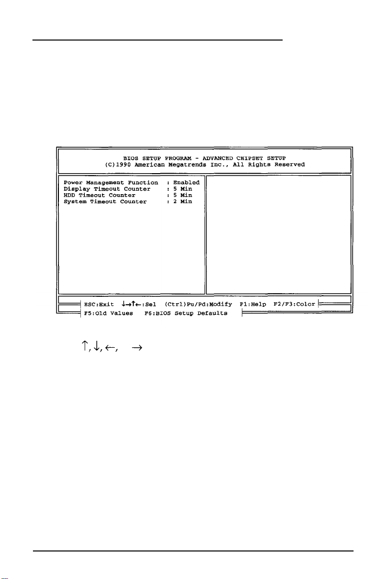
Changing the Advanced Chipset Setup
These configuration settings include the power management
functions that allow you to conserve battery power.
When you select the ADVANCED CHIPSET SETUP option from the
main menu, you see this screen:
Press or to select the option you want to change. When
an option is highlighted, you can press
about the option including the possible settings. Use
F1 to display information
PgUp or
PgDn to change the value of an option. Press ESC to return to the
main menu.
5-10 Running Setup
Page 87

The options on the ADVANCED CHIPSET SETUP screen are
described in the following table. You can display the possible
settings for each option when the option is highlighted and you
press the
ADVANCED CHIPSET SETUP options
F1
key.
Option
Power Management
Function
Display Timeout
Counter
HDD Timeout Counter
System Timeout
Counter
Function
Enables or disables the power management
functions; if enabled, you can set the next three
counters
Enables or disables a timeout period for the LCD
display; if enabled, the computer goes into
Suspend mode when there is no activity on the
LCD screen for the specified period of time
Enables or disables a timeout period for the
hard disk drive; if enabled, the computer goes
into Suspend mode when the hard disk drive is
not accessed for the specified period of time
Enables or disables a timeout period for the
system; if enabled, the computer goes into
Suspend mode when the system is not accessed
for the specified period of time
Highlight the option you want to change and press F1 to see what
timeout periods are available. If you do not use the keyboard for
the specified amount of time, the computer turns off the LCD
screen, hard disk drive, or the entire system to save battery power.
The next time you press a key, the system comes back on. It’s a
good idea to always press the
Shift key when you want to resume
activity on the computer.
Running Setup
5-11
Page 88

Changing the Password
If you enable the Password Checking option on the
ADVANCED CMOS SETUP screen, you use the CHANGE
PASSWORD option to specify the password.
Caution
If you do set a password, be sure it is easy to remember, If you
forget your password, you will have to call the Epson
Connection for assistance.
When you select the
following prompt:
CHANGE PASSWORD option, you see the
Enter CURRENT Password:
Type the current password. (When you enable a password for the
first time, the current password is AMI.) You see the following
prompt
Enter NEW password:
Type your password using up to six characters. To protect your
password, the screen does not display what you type. After typing
the password, press
Enter. Then you see the following prompt:
Re-Enter NEW Password:
Type the same password again and press
Enter. (This confirms
your password for the system.) The program displays the
following message
NEW Password Installed
Press ESC to return to the main menu screen. Highlight WRITE TO
CMOS AND EXIT and press Enter.
5-12
Running Setup
Page 89

Now, you must enter the password each time you start or reset the
computer and/or before the Setup program will start. (See
Chapter 2 for information about using the password you have
defined.)
Hard Disk Utility
You need to select this option only if you are having serious
problems with your hard disk, such as not being able to access it.
This option provides utilities that allow you to perform a low-level
(or physical) format of your hard disk. Do not confuse this
procedure with the logical format performed by your operating
system. The physical formatting of a hard disk is a separate step
that is usually done at the factory by the disk manufacturer.
Caution
Physically formatting a hard disk erases any data it contains. Be
sure to backup any data on your hard disk before you format
it. If you are unsure whether formatting is necessary, contact
your Authorized Epson Servicer or call the Epson Connection
(1-800-922-8911) for assistance.
In addition to destroying all the data on the hard disk, formatting
removes any partitions and logical formatting defined on the disk
by your operating system. After you physically format a hard disk,
you need to logically format the disk again using your operating
system.
Running Setup 5-13
Page 90

When you select the HARD DISK UTILITY from the main Setup
menu, you see this screen:
The three options listed on the bottom half of the screen are hard
disk diagnostic tests. These tests are destructive in that they
destroy data on the hard disk. Therefore, if possible, be sure to
back up any data on your hard disk before performing these tests.
Hard Disk Format
The hard disk in your computer has already been formatted for
you. You need to-reformat this hard disk only if you have a serious
problem with the drive. However, before formatting a disk with
data on it, try every other recovery procedure described in your
operating system manuals. Then, if possible, backup all the data
on the disk before you begin.
You must still partition and format the hard disk for the operating
system after performing this low-level format. See your operating
system manuals for instructions.
5-14 Running Setup
Page 91
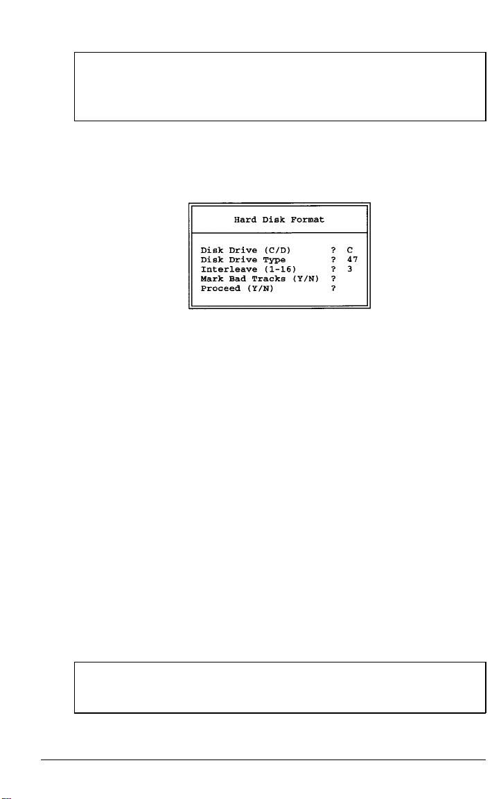
Caution
The hard disk format procedure destroys any data on your hard
disk.
Select the Hard Disk Format option only when you need to
perform a low-level format of the hard disk. You see this screen:
The Mark Bad Tracks option allows you to specify the bad
tracks on the hard disk. If you do not enter a bad track list before
you format the disk, the format program analyzes the surface of
the hard disk to determine the bad tracks.
Auto Interleave
This option is provided for service personnel only. You should
never select this option. Using it incorrectly could damage the
drive.
Media Analysis
This test identifies the bad tracks on the hard disk by analyzing the
surface of the disk to find them. You should not select this option
unless advised to do so by an authorized Epson representative.
Caution
The Media Analysis test destroys any data on your hard disk.
Running Setup
5-15
Page 92

Chapter 6
Using the
Your hard disk drive contains special VGA (video graphics array)
drivers and utilities for your computer’s built-in VGA controller.
This chapter describes how to install and use these drivers and
utilities.
VGA
Utilities
Note
You need to install the drivers only if you plan to use an
external VGA or SVGA monitor. Your LCD screen, which
provides a VGA resolution of 640 x 480 with 32 shades of gray,
does not require a driver.
Because software programs can run on different types of display
adapters with different types of monitors, the VGA drivers
identify your display adapter and monitor for the software. These
drivers are files your software uses to communicate with your
display adapter and monitor.
A utility is a program that supports the processes of a computer.
The VGACONF utility allows you to change the system’s default
graphic configuration and enhance your system operation by
setting various video modes.
The ActionNote’s built-in VGA adapter is 100% compatible with
®
VGA. This adapter allows you to use the computer with
IBM
Epson VGA monitors, other brands of VGA monitors, and
VGA-compatible, multifrequency monitors that use analog input.
The drivers and utilities described in this chapter work with any of
these monitors.
Using the VGA Utilities 6-1
Page 93

Standard VGA monitors display resolutions up to 640 x 480, and
you do not need to install any drivers for an external monitor to
operate properly with your application programs at this
resolution. However, the display drivers provide resolutions up to
800 x 600 in 16 colors for Windows applications.
To obtain drivers for other applications, call the Epson Connection.
Note
These drivers and utilities are designed for systems running
MS-DOS. If you are using another operating system, see the
documentation that came with it for information about the
VGA drivers you can use.
If you are displaying data simultaneously on both the LCD and an
external monitor, the screens will default to a resolution of 640 x
480 regardless of what drivers are loaded. (This is because the LCD
supports 640 x 480 only,) To display in a resolution of 800x 600,
make sure you are displaying on the external monitor only.
You can control where data is displayed using the VGACONF
utility described later in this chapter.
Microsoft Windows, Version 3.1
The Microsoft Windows drivers support a resolution of 800 x 600
with 16 colors.
To install the drivers, follow these steps:
1. Log onto the Windows directory on your hard disk.
2. At the command prompt, type SETUP and press
3. At the System information screen, select Display and
press
Enter.
6-2
Using the VGA Utilities
Enter.
Page 94

4. From the Display menu, select Other (Requires disk
provided by
press
Enter.
5. The program prompts you to insert your display driver diskette
into drive A.
a hardware manufacturer) and
6. Replace A: \ with C: \VGAUTILS\
Enter.
associated resolutions. For example:
7. Select the display driver you want and press
8. Complete the Windows Setup.
The program displays a list of drivers and their
Cirrus Logic VGA 800x600 (16 colors)
as the pathname and press
Enter.
Using the VGACONF Utility Program
Your hard disk drive includes the utility program, VGACONF.
This program is located
This utility allows you to change your system’s default graphic
configuration. Follow these steps to run VGACONF:
1. Log onto the C:\ VGAUTILS directory.
2. Type VGACONF and press
in the VGAUTILS directory.
Enter. You see this main menu:
Using the VGA Utilities 6-3
Page 95

Use or to highlight the selection you want and press
Enter.
The sections below explain each option on the main menu.
Viewing the Display Status
The Display Status option displays the current settings.
For example:
Press any key to return to the main menu.
Changing Settings with Select Option
Select Option allows you to change the current settings. You
see this screen:
6-4
Using the VGA Utilities
Page 96

Highlight the option you want to change and press Enter.
You see a submenu of the available selections. Use or
to highlight the desired setting and press
ESC to return to the
SELECT OPTION menu.
Some options are designed for a specific display mode: CRT,
SimulSCAN, or panel. CRT mode refers to a VGA monitor
connected to the
VIDEO
port; SimulSCAN refers to both the LCD
screen and a VGA monitor; panel refers to the LCD screen. The
following table shows the display modes available for each option.
VGACONF display modes
Option
Reverse
Bold
Contrast enhancement
Expand SimulSCAN, panel
Vertical position
Display CRT, SimulSCAN, panel
Bus width CRT, SimulSCAN, panel
Inhibit font
Cursor
RGB
Display mode
SimulSCAN, panel
Panel
Panel
Panel
CRT, SimulSCAN, panel
Panel
Panel
I
I
Using the VGA Utilities 6-5
Page 97

Setting the Standby Timer
Standby Timer allows you to set a timeout period for the LCD
display panel if the Display option is set to PANEL. When you
select Standby Timer you see this menu:
Select Timer
standby mode. When you select Timer, you see these prompts:
Standby Time (minutes) :
Time-out on (K)eyboard activity or (M) emery
access (K/M) :
Enter the number of minutes to wait before entering standby mode
and press
If you enter K, the LCD panel will enter standby mode if there is
no keyboard activity for the specified number of minutes. If you
enter M, the LCD panel will enter standby mode if video memory
is not accessed for the specified number of minutes. Press PgDn to
initiate the timer.
The standby mode initiated by the VGACONF utility does not
work in Windows. You may prefer to use the power management
features available through Setup.
Select Quit to exit the VGACONF program and return to the
operating system prompt.
to set a timeout period, or select Normal to disable
Enter.
Then enter K or M to indicate the type of activity.
6-6 Using the VGA Utilities
Page 98

Using VGACONF From the Command Line
To quickly change one or more VGA configuration settings, you
can access VGACONF from the command line with option
parameters. At the command prompt, enter the VGACONF
command in the following format:
VGACONF [options]
In place of the options parameter, substitute one or more of the
following option names, separated by spaces.
VGACONF command options
Option name Function
–? or -H
Display the help screen
-S
-N
-K=xx Set standby timer for keyboard to xx minutes
-M=xx
ETDG Enable text and disable graphics reverse video mode
NOREVERSE
REVERSE Enable text and graphics reverse video
DTEG Disable text and enable graphics reverse video
BOLD Enable bold mode
NOBOLD Disable bold mode
ATTREMUL
NOATTREMUL
BKGND
FRGND
BKFRGND
EXPAND Enable expand mode
Display status information
Disable standby mode
Set standby timer for memory access to xx minutes
Disable text and graphics reverse video
Disable Automap
Enable Automap
Enable background enhancement
Enable foreground enhancement
Enable background and foregound enhancement
Using the VGA Utilities 6-7
Page 99

VGACONF command options (continued)
Option name
NOEXPAND Disable expand mode
CENTER Center the screen on the panel
TOP
BOTTOM
PANEL Switch the display to the panel
Function
Align the screen on the top of the panel
Align the screen on the bottom of the panel
CRT
SIMUL Use the panel and the CRT simultaneously
16BIT Enable 16-bit operations
NO16BIT Force 8-bit operations
INHFONT
NOI Allow font loading when switching display
FULLHGT
NOFULLHGT
W259
W529
W295 Select RGB weighting 2:9:5
W592 Select RGB weighting 5:9:2
W925
W952 Select RGB weighting 9:5:2
Switch the display to the CRT (monitor)
Inhibit font loading when switching display
Select full height cursor
Select normal cursor
Select RGB weighting 2:5:9
Select RGB weighting 5:2:9
Select RGB weighting 9:2:5
You can abbreviate any of the VGACONF options by typing only
the first three characters of the option name. The following
examples show sample VGACONF commands:
VGACONF SIMUL
VGACONF
SIM
VGACONF PANEL NOATTREMUL NOBOLD NOEXPAND
VGACONF PAN NOA NOB NOE
VGACONF -S
VGACONF -M=4
6-8 Using the VGA Utilities
Page 100

Appendix A
Troubleshooting
You probably won’t encounter any difficulties as you setup and
use your ActionNote. If anything out of the ordinary happens,
refer to this appendix for help. It provides you with the following
problem-solving sections:
The computer won’t start
Battery problems
AC adapter problems
The LCD screen is blank
The external monitor screen is blank
The computer locks up
Password problems
Diskette problems
Diskette drive problems
Hard disk problems
Software problems
Printer problems
Memory module problems
Trackball or pointing device problems
External keyboard problems
Troubleshooting
A-1
 Loading...