

Page 1
ROM
Video RAM
Shadow RAM
EPSON
128KB
system BIOS, video BIOS, and
Setup code located in
system board
256KB
DRAM on main system board
Supports shadowing of system and video
BIOS ROM into RAM
OT-PROM on
ActionNote
main
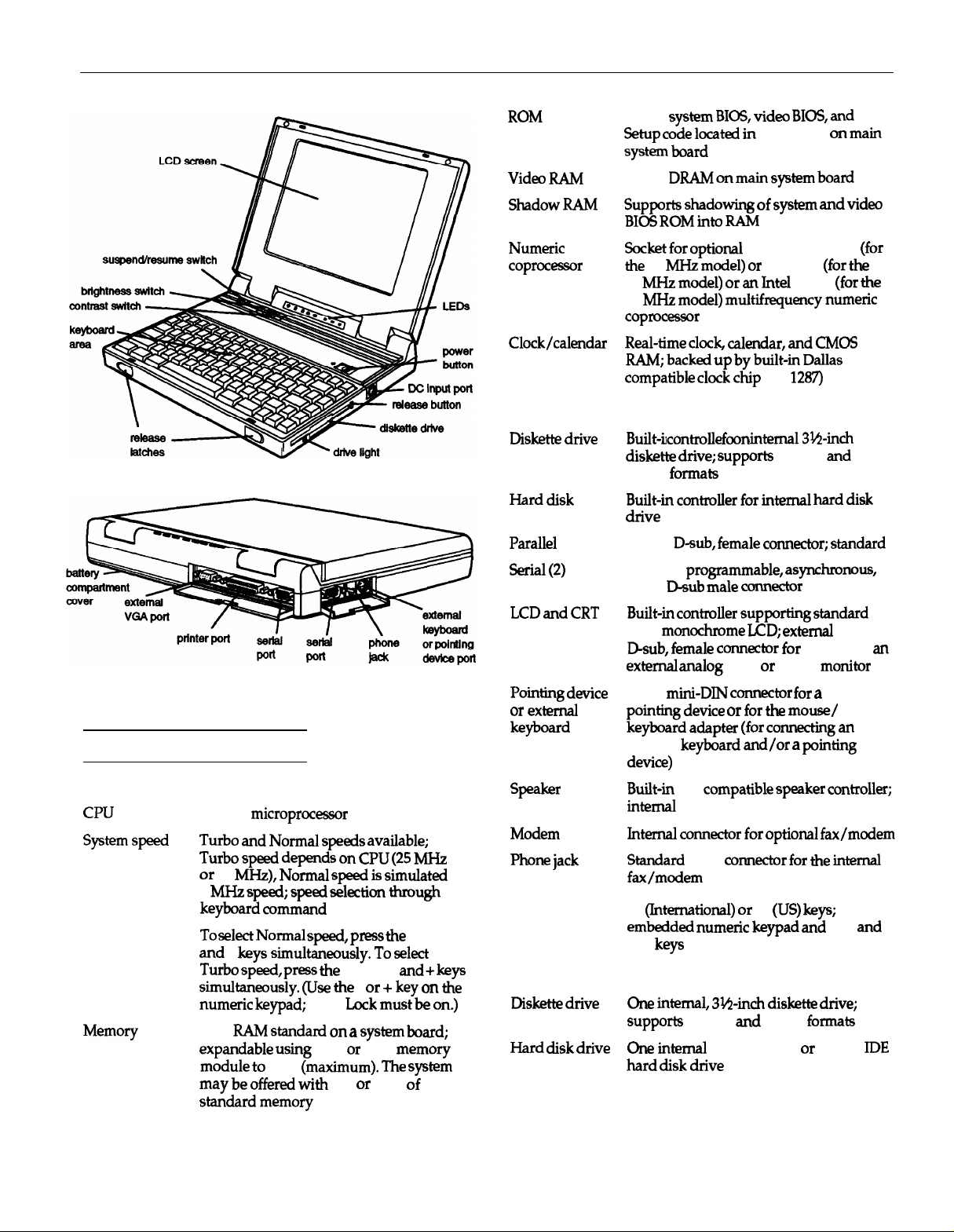
Computer Specifications
Main Unit
CPU
System speed
Memory
486SLC
Turbo and Normal speeds available;
Turbo speed depends
or 33
8
keyboard command
To select Normal speed, press the
and
Turbo speed, press the
simultaneously. (Use the
numeric keypad;
2MB
expandable using
module to
may be offered with
standard memory
microprocessor
MHz), Normal speed is simulated
MHz speed; speed selection through
-
keys simultaneously. To select
Num
RAM standard
8MB
on a
2MB or 6MB
(maximum). The system
2,4, or 8MB
on
CPU (25 MHz
Ctrl, Alt,
Ctrl, Alt,
Lock must be on.)
and + keys
- or +
key on the
system board;
memory
of
Numeric
coprocessor
Clock/calendar
Controllers
Diskette drive
Hard disk
Parallel
Serial (2)
LCD and CRT
Pointing device
or external
keyboard
Speaker
Modem
Phone jack
Keyboard
Mass Storage
Diskette drive
Hard disk drive
Socket for optional
the
33
MHz model) or
25
MHz model)
25
MHz model) multifrequency numeric
coprocessor
Real-time clock, calendar, and CMOS
RAM; backed up by built-in Dallas
compatible clock chip
Built-in controller for one internal
diskette drive; supports
720KB
formats
Built-in controller for internal hard disk
drive
25-pin,
D-sub, female connector; standard
RS-232C,
9-pin,
Built-in controller supporting standard
VGA
D-sub, female connector for
external analog
6-pin,
pointing device or for the mouse/
keyboard adapter (for connecting an
external
device)
Built-in
internal
Internal connector for optional fax/modem
Standard
fax/modem
85
embedded numeric keypad and F11
F12
One internal, 3tl-inch diskette drive;
supports
One internal 80MB, 120MB, or 180MB
hard disk drive
programmable, asynchronous,
D-sub male connector
monochrome LCD; external
mini-DIN connector for a
keyboard and/or a pointing
ISA
RJ-11
(International) or
keys
1.44MB
CyrixCx 83S87-33
83S87-25
or an
Intel
387SX
(DS
1287)
1.44MB
connectig
VGA or SVGA
compatible speaker controller;
connector for the internal
84
(US) keys;
and
720KB
formats
(for
(for the
(for the
3 1/2-inch
and
15-pin,
an
monitor
PS/2-type
and
IDE
7/27/93
ActionNote-1
Page 2
EPSON ActionNote
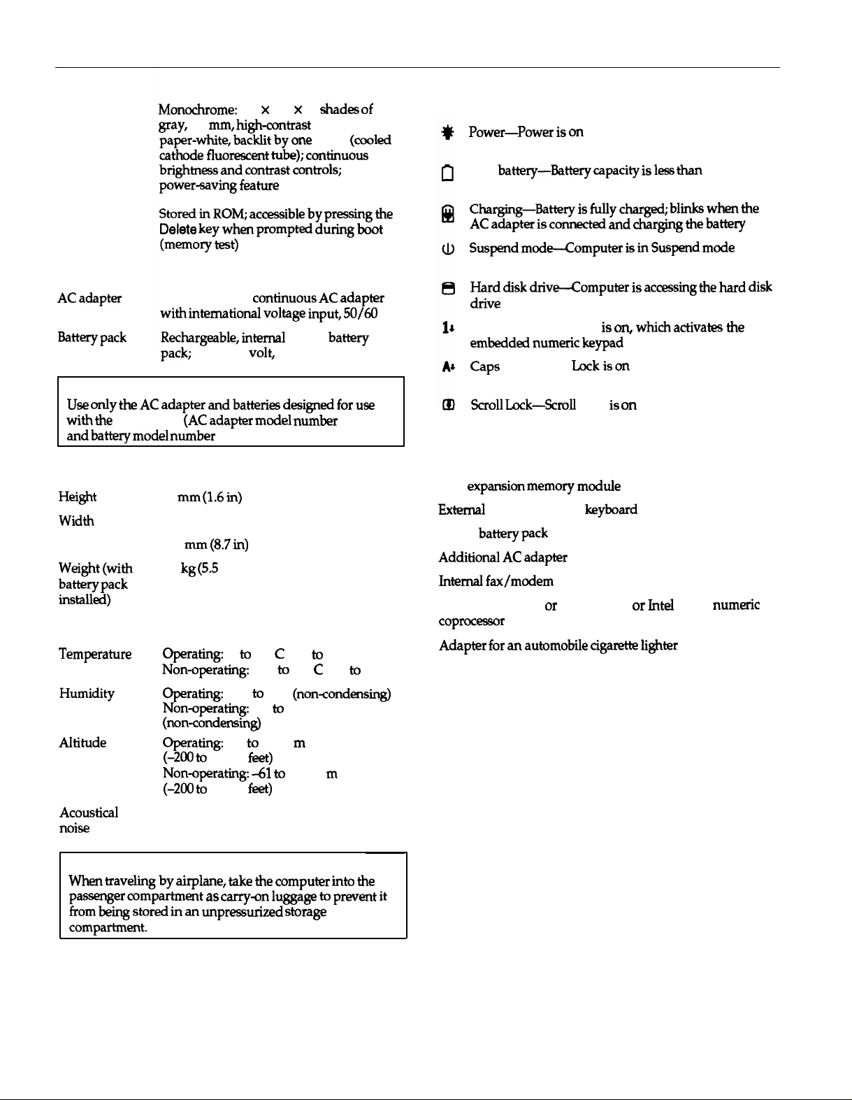
LCD Display
Setup Program
Monochrome:
gray,
paper-white, backlit by one
cathode fluorescent tube); continuous
brightness and contrast controls;
power-saving feature
Stored in ROM; accessible by pressing the
Delete key when prompted during boot
(memory test)
0.3
640 x 480 x 32
mm, high-contrast
shades
2-film;
CCFT
Power Supply
AC adapter
Battery pack
Caution
Use only the AC adapter and batteries designed for use
with the
and battery model number
ActionNote
+15.5VDC, 2.4.A continuous AC adapter
with international voltage input, 50/60
Rechargeable, internal
pack; 8-cell, 9.6 volt, 1.7AH, 16.3W
(AC adapter model number
8KR-1700AE).
NiCad
battery
AP-3S25
Physical Dimensions
Height
Width
Depth
weight (with
battery pack
installed)
42 mm
(1.6 in)
280mm
225 mm
2.5 kg
(8.7 in)
(5.5
lbs)
Environmental Requirements
Temperature
Humidity
Altitude
Operating:
Non-operating:
Operating:
Non-operating:
(non-condensing)
Operating:
(-200 to 10,000
Non-operating:
(-200 to 35,000
5° to 35° C (41° to 95° F)
-20° to 60° C (-4° to 140° F)
30% to 90%
5% to 95%
-61 to 3,048
feet)
-61 to 10,668
feet)
(non-condensing)
m
m
of
(cooled
Hz
LEDs
Power-Power is
Low
battery-Battery capacity is less than
Charging-Battery is
AC adapter is connected and charging the battery
Suspend mode-Computer is in Suspend mode
Hard disk
drive
Num Lock-Num Lock is
embedded numeric keypad
Caps
Scroll Lock-Scroll
drive-Computer is
Lock--caps
on
20%
fully charged; blinks when the
accessing the hard disk
on, which activates the
Lock is on
Lock is
on
Options
6MB
expansion memory module
External
NiCad
Additional AC adapter
Internal fax/modem
Cyrix Cx 83S87-33, or Cx 83S87-25, or Intel 387SX numeric
coprocessor
Adapter for an automobile cigarette lighter
PS/2-compatible
battery pack
keyboard
Acoustical
noise
20 dB
Caution
When traveling by airplane, take the computer into the
passenger compartment as carry-on luggage to prevent it
from being stored in an unpressurized storage
compartment.
ActionNote-2
7/27/93
Page 3
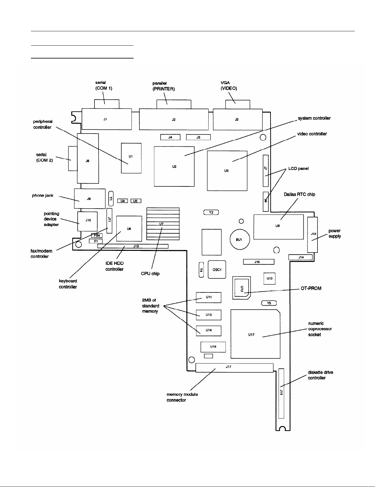
Main System Board Diagram
EPSON ActionNote
7/27l93
ActionNote-
Page 4

EPSON ActionNote
Major Subassemblies
CPU chip
\
numeric
coprocessor
fax/modem
(optional)
\
/
video
controller
I
\
3
l&inch,
diskette drive
1.44MB
Connector Pin Assignments
Dallas clock
power
supply
Serial Port Connectors (J1 and J6)
Serial Port Connector Pin Assignments
I
Pin I Signal
1
Data carrier detect
2
Receive data
3
Transmit data
4 Data terminal ready
5
Signal GND
Pin I Signal
6
Data set ready
7
Request to send
8
Clear to send
9
Ring indicator
I
Pointing Device Connector (J10)
This connector supports simultaneous use of a pointing
device and an external keyboard when the mouse/keyboard
adapter is attached.
Parallel Port Connector (J2)
pin 13
I
pin 1
l oooooooooo~
I I
pin 25
Parallel Port Connector Pin Assignments
pin 14
Pointing Device Connector Pin Assignments
Pin
Signal
1
I
Keyboard Data
2
Pointing device data
13 1
Ground
Signal
Pin
4
+5 VDC (fused)
Clock, keyboard
5
1 61
Clock, pointing device
I
VGA Port Connector (J3)
pin 5
pin 10
pin 15
VGA Port Connector Pin Assignments
Pin Signal
1
Red
2
Green
3 Blue
4
MS2
5
Ground
Pin Signal
6
Ground
7
Ground
a
Ground
9
Unused
10
Ground
pin 1
pin 6
pin 11
Pin Signal
11
MS0
12 MS1
13
Horizontal sync
14
Vertical sync
15 Unused
ActionNote-
7/27/93
Page 5

EPSON ActionNote
Internal Keyboard Connector (J14)
Internal Keyboard Connector Pin Assignments
Internal Keyboard Connector (Jl5)
Internal Keyboard Connector Pin Assignments
Pin
1
2-12
Signal
caps Lock
Keyboard data line
DC-DC Power Connector (J12)
pin 22
AC-DC Power Connector (JP1)
pin 3
pin 1
Power Connector Pin Assignments
pin 4
pin 2
LED Connector (J5)
LED Connector Pin Assignments
Pin Signal Pin Signal
1
15
2
3
4
Ground
Hard disk drive
caps Lock
Num Lock
1
Scroll Lock
LED
6
7
8 BATTLO
9
1
10
Charging
/LOSPD
Ground
1+5v
Suspend/Resume Connector (J4)
I
Power Connector Pin Assignments
Pin Signal
1
Ground
2
Ground
3
Ground
4
Ground
5 EXTAC
Ground
6
BATLO
7
+24 VDC
8
LCD ON
9
10
1+24VDC
11
]Vin
Pin Signal
12 Vcc
13 Vcc
14 Vcc
15 Vcc
16
17
18 CHARGE
19 Vin
20
21
22
+12 VDC
VCCSUS
CONTR VR+
FULLPON
CONTR VR-
pin 21
Suspend/Resume
Pin Signal
1
2
3 CONTR_VR+
A
Connector Pin
Ground
CONTR_VR-
RI VR
Assignments
Pin
5 BL_VR+
6
7
8 SUS/RES
Signal
Ground
Ground
7/27/93
ActionNote-
Page 6

EPSON ActionNote
Diskette Drive Cable Connector (J18)
pin 26
1111111111111111111111111
Diskette Drive Connector Pin Assignments
2
4
1
16
Pin
6
8,13
9
10
12
14
Signal
/INDEX
/DRV0
DSKCHG
Reserved
1
RPM/LC
1
/MTR0
1
DIR
1
/STEP
1
/WDATA
Pin
18 WGATE
20
22 /WRPRT
24 /RDATA
26
1-11
(odd)
15-25
I
(odd)
Signal
/TRK0
HDSEL
+5VDC
Ground
IDE Hard Disk Drive Connector (J13)
IDE Hard Disk Drive Connector Pin Assignments
Pin Signal
/RESET
1
Ground
2
D7 17
3
D8
4
D6
5
D9
6
171 D5
1
D10
8
ID4
9
D11
10
D3
11
D12
12
D2
13
D13
14
Pin Signal
D1
15
16 D14 30
D0
D15
18
Ground
19
20
121
I22I Ground
123
Reserved
1
Resewed I35 1 HA0
136
137
24
25
26
27
28
l/low
Ground
/IOR
Ground
CHRDY
Reserved
Pin Signal
29
31
32
33
34
38 /HDCS1
39
40,43
41,42
44
Resewed
Ground
IRQ14
/IOCS16
HA1
Reserved
IHA
lMDcs0
/LEDHDD
Ground
+5V
+5V
pin 1
Fax/modem Connector (J11)
/
pin 15
Fax/modem Connector Pin Assignments
\
pin 1
LCD Panel Connector (J7)
LCD Connector Pin Assignments
LCD (CCFT) Inverter Connector (J9)
LCD (CCFT) Inverter Connector Pin Assignments
ActionNote-
7/27/93
Page 7

EPSON
ActionNote
DMA Assignments
Hardware Interrupts
Hard Disk Drive Types
* BIOS dependent
Note: Type 47 must be selected to enter User Defined drive specifications.
Information Reference List
Engineering Change Notices
None.
Technical Information Bulletins
None.
Product Support Bulletins
None.
System I/O Address Map
Related Documentation
TM-ACTNOTE
ADDACTNOT33
PL-ACTNOTE
SPKACTNOT33
400210900
400211000
Epson ActionNote Service Manual
ActionNote Service Manual Addendum
Epson ActionNote Parts Price List
Epson ActionNote Self Paced Kit
Epson ActionNote User’s Guide
Epson ActionNote Quick Reference
7/27/93
ActionNote-
 Loading...