

Page 1
Epson EL 486UC+
EL 486UC+ Specifications
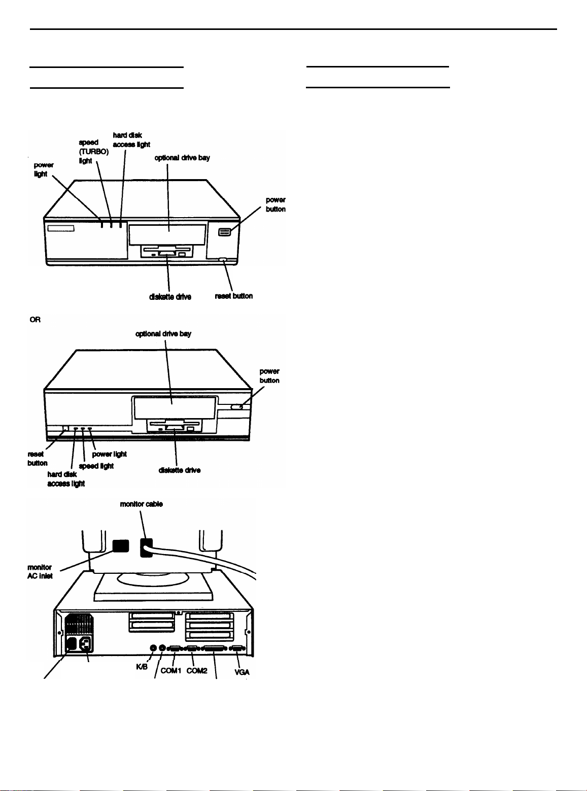
The following diagrams illustrate the outside of the
EL 486UC+ system.
Computer Specifications
CPU and Memory
32-bit CPU
System speed
Memory
ROM
Intel 486SX/25 microprocessor;
upgradable to 486SX/33, 486DX/33,
486DX2/50, or 486DX2/66
Fast and slow speeds available; fast speed
is 25 MHz or the speed of your upgraded
microprocessor, slow speed is 8 MHz;
speed selection through keyboard
commands or jumper setting
To select slow speed, press Ctrl Alt and-;
to select fasts peed, press Ctrl Alt and+
(use the - or + key on the numeric keypad)
4MB RAM standard on a SIMM;
expandable to 64MB using 1MB, 2MB,
4MB, 8MB, 16MB, and 32MB SIMMs
(64MB maximum requires the use of 32MB
SIMMs; SIMMs must be tin-plated,
72-pin, 32-bit or 36-bit fast-page mode
type with access speed of 70ns or faster
128KB system BIOS, video BIOS, and
SETUP code located in EPROM on main
systemboard
\
AC inlet
AC outlet
MOUSE
PARALLEL
Video RAM
Shadow RAM
Memory
relocation
Cache
Math
coprocessor
Clock/calendar
Controllers
Video
512KB DRAM on main system board;
expandable to 1MB using 70ns or 80ns,
256 x 4
Supports shadowing of system and video
BIOS ROM into RAM
Supports relocation of 256KB of memory
from A0000h to BFFFFh and D0000h to
EFFFFh to extended memory
8KB of internal cache (built into the
microprocessor); supports 64KB, 128KB, or
256KB
8x8, 20ns DIP chips or 28-pin, 32x8,
20ns DlP chips
Math coprocessor built into the
microprocessor for DX and DX2 systems
Contained in the 82C491 system controller
along with 64 bytes of CMOS RAM;
backed up by a soldered NiCad
rechargeable battery
Trident 8900CL VGA controller on main
system board; provides resolutions up to
1024 x 768 in 16 colors (up to 1024 x 768 in
256
bit,
20-pin,
of external cache using 28-pin,
colors with 1MB of video memory)
DIP DRAM chips
12/1/93
Epson EL 486UC+-1
Page 2
Epson
EL 486UC+
Diskette
Hard disk
Interfaces
Monitor
Parallel
Serial
Keyboard
Mouse
Option slots
Speaker
Controller on main system board supports
up to two diskette drives or one diskette
drive and one tape drive
Interface on main system board supports
up to two IDE hard disk drives with
built-in controller; BIOS provides hard
disk auto-sensing function
VGA interface for fixed or multi-frequency
monitor built into system board; 15-pin,
D-shell connector
One standard 8-bit parallel (bi-directional)
interface built into main system board;
25-pin, D-shell connector
Two RS-232C, programmable,
asynchronous interfaces built into main
system board; 9-pin, D-shell connectors
PS/2 compatible keyboard interface built
into main system board; 6-pin, mini DIN
PS/2
compatible mouse interface built
into main system board; 6-pin mini DIN
connector
Three 16-bit, full-length and two 8-bit,
half-length I/O expansion slots, ISA
compatible, 8.33 MHz bus speed
Internal
Keyboard
SETUP
Program
System
security
Physical characteristics
Width 15.6 inches (3% mm)
Depth
Height
Weight
Detachable, two-position height; 101 or
102 sculpted keys; countrydependent
main typewriter keyboard;
numeric/cursor control keypad; four-key
cursor control keypad; 12 function keys
Stored in ROM; accessible by pressing
duringboot
User and supervisor level passwords
(8 characters) available for system boot or
diskette access
14.5 inches (368 mm)
4.1 inches (104 mm)
15 lb (6.8 kg), without drives or keyboard
Power Supply
Type
Input ranges
Maximum
outputs
Frequency
Cables
65 Watt, UL listed, fan-cooled
90 to 115,230 to 260 VAC
+5
VDC at 7.5 Amps, -5 VDC at
0.1 Amp, +12 VDC at 2.0 Amps,
-12 VDC at 0.2 Amps
50/60Hz
Two to main system board; four to mass
storage devices
F2
Mass storage
Diskette drives
Hard disk
drives
Other devices
Internal mounts:
Two
with three or more option cards installed,
the power supply supports only one
internal drive
Externally accessible mounts:
One
and one
storage capacity
storage capacity
to half-height size (on a system with three
or more option cards, the installation of a
second hard disk drive may overload the
power supply)
Half-height tape drive, CD-ROM, optical
drive, or other storage device;
wide, one-inch high drives;
wide, one-inch high drive
wide, half-height drive
diskette drive, 720KB or 1.44MB
diskette drive, 360KB or 1.2MB
form factor hard disk drive(s), up
or
with mounting frames
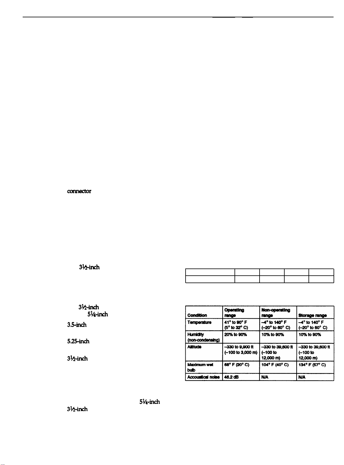
Option Slot Power Limits
Maximum current
For all slots*
* Based on a system containing one hard disk drive and one diskette drive.
+5 Volts
4.6 Amps 0.1 Amp
-5 Volts
+12 Volts
1.1 Amps
-12 Volts
0.1 Amp
Environmental Requirements
Epson EL 486UC+-2
12/1/93
Page 3
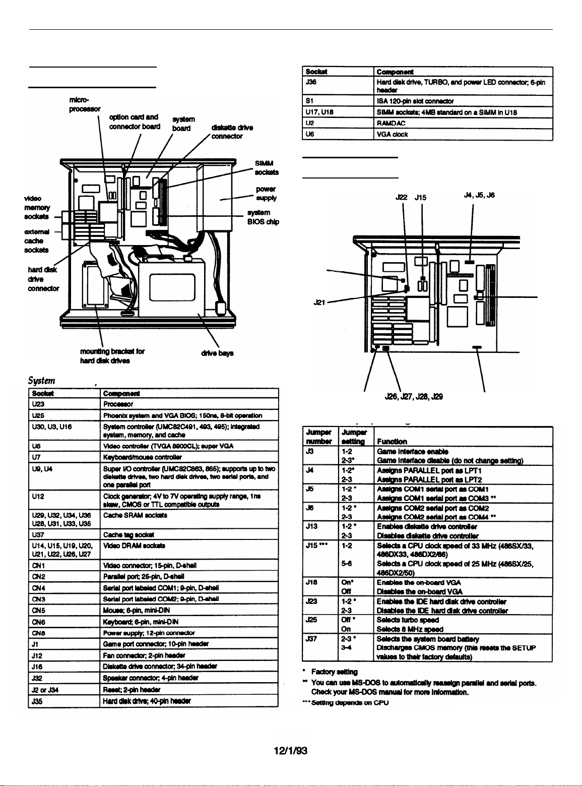
Major Subassemblies
Jumper Settings
J19
Epson
EL 486UC+
J23
J25
Miscellaneous jumper settings
J37
Epson EL 486UC+-3
Page 4

Epson EL 486UC+
External cache jumper settings*
*If you have no external cache installed, the position of these jumpers does
not matter.
Video memory configuration
* Standard video memory
Video resolutions and colors
Processor type jumper setting
486DX, DX2
486SX
J21
1-2,3-4
2-3
J22
1-2
Off
SIMM Installation
Your computer comes with 4MB of memory on a SIMM. You
can increase the memory up to 64MB by installing 1MB, 2MB,
4MB, 8MB, 16MB, and 32MB (when available) SIMMs in the
computer’s two SIMM sockets. The following table shows the
possible SIMM configurations; any SIMM can be installed in
eitherbank.
Sample SlMM configurations
External Cache
You can install 64KB, 128KB, or 256KB of external cache on
the EL 486UC+.
To install 64KB of external cache, use eight SRAM, 28-pin,
8K x 8, 20ns DIP chips, and one 8K x 8, 20ns tag chip
To install 128KB of external cache, use four SRAM, 28-pin,
32K x 8, 20ns DIP chips, and one 32K x 8, 20ns tag chip
For the cache memory to work properly, you must install
chips in the following configuration (each bank contains four
cache memory sockets).
Microprocessor Upgrades
The computer’s processor can be upgraded by replacing the
existing microprocesso
Use only tin-plated, 32-bit or 36-bit, 72-pin, fast-page mode
SIMMs that operate at an access speed of 70ns (nanoseconds)
or faster. Be sure all the SIMMs operate at the same speed.
purchase an upgrade kit from Epson or buy the individual
components separately, as listed in the following table.
Microprocessor upgrade components
Video Memory
The EL 486UC+ comes with 512KB of video memory
installed on the main system board. You can increase the
video memory to 1MB by installing four additional DRAM,
20-pin, 70ns or 80ns, 256KB x 4-bit DIP chips.
* For the SX/25, SX/33, and DX/33 processors
To install 256KB of external cache, use eight SRAM, 28-pin,
32K x 8, 20ns DIP chips, and one 32K x 8, 20ns tag chip.
r with a faster one. You can either
Epson EL 486UC+-4
12/1/93
Page 5

Epson
EL 486UC+
The SX/25, SX/33, and DX/33
The DX2/50 and DX2/66 processors require a heat sink and
a fan. Make sure jumpers J21, J22, and J15 are set correctly for
the new processor.
rocessors require a heat sink.
p
Hard Disk Drive Types
The EL 486UC+ comes with a hard disk auto-sensing feature.
when you press
Autotype
detects the type of hard disk drive you have installed and fills
in the drive information using values in the following table.
Some older or preformatted drives do not support the autosensing feature. If the parameters displayed do not match the
parameters of your hard disk drive, you can define your own
drive type in SETUP.
Hard disk drive types
Enter
with the cursor positioned on the
Fixed Disk
option in SETUP, the system
Drive Option Information
Hard disk drive
options
for 1-inch IDE drives**
* Select 1 or none for the precomp value. If neither of these options are
available, select the maximum available precomp value.
** Actual hard disk drive installed is subject to availability.
IDE hard disk drive jumper settings
12/1/93
Epson EL 486UC+-5
Page 6

Standard diskette drive specifications
DMA Assignments
System Memory Map
000FFFFFFh
00100000h
Hardware Interrupts
000C0000h
000A0000h
Epson EL 486UC+-6
12/1/93
Page 7

Epson
EL 486UC+
System l/O Address Map
Connector Pin Assignments
Parallel port connector pin assignments (CN3)
Serial port connector pin assignments (CN4 and CN5)
Keyboard and mouse connector pin assignments (CN7 and CN6)
VGA port connector pin assignments (CN2)
Power supply connector pin assignments (CN8)
Diskette drive connector pin assignments (J16)*
*All odd-numbered pins are grounds
12/1/93
Epson EL 486UC+-7
Page 8

Epson
EL 486UC+
Epson EL486UC+-8
12/1/93
Page 9

Epson EL 486UC+
Installation/Support Tips
Installing Diskette Drives
Make sure that the drive type has been correctly selected in
the SETUP program.
Installing Hard Disk Drives
When installing a hard disk drive, see the hard disk drive
type tables and use the auto-sensing feature in SETUP to
select the correct type number for the drive. If the
auto-sensing feature does not produce a match for the
drive, you can define your own drive type by selecting
User as the type and entering the drive’s exact
parameters.
If you plan to install two hard disk drives in the internal
bays, you must use flat-head screws (#6-32UNC x 8
FH,M,+) to
(On a system with three or more option cards, the
installation of a second hard disk drive may overload the
power supply.)
If you are installing an ESDI hard disk drive, make sure
you disable the built-in IDE hard disk drive interface by
moving jumper J23 to position 2-3. Also be sure to remove
the hard disk drive ribbon connector from the system
board.
secure the top drive to the mounting bracket.
COM Port Assignment
If you want to assign COM1 as COM3, you must set jumper
J5 to position 2-3. If you want to assign COM2 as COM4, you
must set jumper J6 to position 2-3.
Booting Sequence
If you cannot boot the computer from the hard disk, make
sure the booting sequence in is set to A: then C:.
Then boot the computer from a system diskette in Drive
Information Reference List
Engineering Change Notices
None.
Technical Information Bulletins
None.
Product Support Bulletins
None.
If you are installing a video adapter card that doesn’t
support VGA, make sure you disable the built-in VGA by
setting jumper J18 to the Off position.
A.
Overheating Problems
Make sure that the DX or DX2 processor has an adequate
heat sink and fan installed to prevent overheating. The
Epson CPU upgrade kit comes with a heat sink and a fan.
Other manufacturer’s kits may not include these items.
Software Problems
When installing a copy-protected software package, first
try the installation at fast speed. If this does not work
properly, select slow speed by pressing Ctrl Alt and the -
key on the numeric keypad. Try loading the program at
slow speed and then switching to fast speed, if possible.
When using a software package that uses a key disk as its
copy-protection method, try loading it at fast speed. If this
does not work, load it at slow speed.
Installing Option Cards
Although the EL 486UC+ will support most full-length
option cards, option cards with an I/F connector on the
back may not fit into the option slot.
Make sure the power requirements of the option cards
you install do not exceed the power supply limitations.
If the computer locks up, the power supply may be
overloaded. On a system with three or more option cards,
the installation of a second hard disk drive may overload
the power supply.
Related Documentation
TM-EL486UC
EL486UC+ADD Epson EL 486UC+ Service Manual
PL-EL486UC+ Epson EL 486UC+ Parts Price List
400275200 Epson EL 486UC+ User’s Guide
Epson EL 486UC Service Manual
Addendum
12/1/93
Epson EL 486UC+ - 9
 Loading...