

Page 1
Page 2

FCC COMPLIANCE STATEMENT FOR AMERICAN USERS
This equipment has been tested and found to comply with the limits for a class B digital
device, pursuant to Part 15 of the FCC Rules. These limits are designed to provide
reasonable protection against harmful interference in a residential installation. This
equipment generates, uses and can radiate radio frequency energy and, if not installed and
used in accordance with the instructions, may cause harmful interference to radio or
television reception. However, there is no guarantee that interference will not occur in a
particular installation. If this equipment does cause interference to radio and television
reception, which can be determined by turning the equipment off and on, the user is
encouraged to try to correct the interference by one or more of the following measures:
0
Reorient or relocate the receiving antenna
Cl
Increase the separation between the equipment and receiver
0
Connect the equipment into an outlet on a circuit different from that to which the
receiver is connected
0
Consult the dealer or an experienced radio/TV technician for help.
WARNING
The connection of a non-shielded equipment interface cable to this equipment will
invalidate the FCC Certification of this device and may cause interference levels which
exceed the limits established by the FCC for this equipment. It is the responsibility of the
user to obtain and use a shielded equipment interface cable with this device. If this
equipment has more than one interface connector, do not leave cables connected to unused
interfaces.
Changes or modifications not expressly approved by the manufacturer could void the
user’s authority to operate the equipment.
FOR CANADIAN USERS
This digital apparatus does not exceed the Class B limits for radio noise emissions from
digital apparatus as set out in the radio interference regulations of the Canadian
Department of Communications.
Le present
applicables aux appareils
brouillage radidlectrique
appareil
numerique
numeriques de
edict6 par le
n’emet pas de
Classe B prescrites dans le
Ministere
bruits
radioelectriques depassant les limites
reglement
des
Communications du Canada.
sur le
Page 3

EPSON®
User’s Guide
Page 4

IMPORTANT NOTICE
DISCLAIMER OF WARRANTY
Epson America makes no representations or warranties, either express or implied, by or
with respect to anything in this manual, and shall not be liable for any implied warranties
of merchantability and fitness for a particular purpose or for any indirect, special, or
consequential damages. Some states do not allow the exclusion of incidental or
consequential damages, so this exclusion may not apply to you.
COPYRIGHT NOTICE
All rights reserved. No part of this publication may be reproduced, stored in a retrieval
system, or transmitted, in any form or by any means, electronic, mechanical,
photocopying, recording, or otherwise, without the prior written permission of Epson
America, Inc. No patent liability is assumed with respect to the use of information
contained herein. Nor is any liability assumed for damages resulting from the use of the
information contained herein. Further, this publication and features described herein are
subject to change without notice.
TRADEMARKS
Epson is a registered trademark of Seiko Epson Corporation.
Equity is a registered trademark of Epson America, Inc.
General notice: Other product names used herein are for identification purposes only and
may be trademarks of their respective companies.
Copyright 0 1992 by Epson America, Inc.
Torrance, California Y73899110100
ii
Page 5

Important Safety Instructions
1.
Read all of these instructions and save them for later reference.
2.
Follow all warnings and instructions marked on the product.
3.
Unplug this product from the wall outlet before cleaning. Use a
damp cloth for cleaning, not liquid cleaners or aerosol cleaners.
4.
Do not use this product near water.
5.
Do not place this product on an unstable cart, stand, or table.
Slots and openings in the cabinet and the back or bottom are
6.
provided for ventilation; these openings must not be blocked or
covered. This product should never be placed near or over a
radiator or heat register.
7.
This product should be operated from the type of power source
indicated on the marking label. If you are not sure of the type of
power available, consult your dealer or local power company.
8.
Connect all equipment to properly grounded (earthed) power
outlets. If you are unable to insert the plug into the outlet,
contact your electrician to replace your obsolete outlet. Avoid
using outlets on the same circuit as photocopiers or air control
systems that regularly switch on and off.
9.
Do not locate this product where the cord will be walked on.
10. If an extension cord is used with this product, make sure that the
total of the ampere ratings on the products plugged into the
extension cord do not exceed the extension cord ampere rating.
Also, make sure that the total of all products plugged into the
wall outlet does not exceed 15 amperes.
11. Never push objects of any kind into this product through the
cabinet slots. Never spill liquid of any kind on the product.
iii
Page 6

12. Except as specifically explained in the User’s Guide, do not
attempt to service this product yourself. Refer all servicing to
qualified service personnel.
13. Unplug this product from the wall outlet and refer servicing to
qualified service personnel under the following conditions:
When the power cord or plug is damaged.
A.
If liquid has entered the product.
B.
If the product does not operate normally when the operating
C.
instructions are followed. Adjust only those controls that are
covered by the operating instructions, since improper
adjustment of other controls may result in damage and will
often require extensive work by a qualified technician to
restore the product to normal operation.
If the product has been dropped or the cabinet has been
D.
damaged.
If the product exhibits a distinct change in performance.
E.
iv
Page 7

Importantes Mesures de
S&wit6
V
Page 8

vi
Page 9

Contents
Introduction
Optional Equipment
Operating Systems and Other Software
VGA Utilities
How to Use This Manual
Where to Get Help
Chapter 1
1 Choosing a Location
2 Removing the Protector Card
3 Connecting a Monitor
Using the VGA Interface
Using a Display Adapter Card
4 Connecting a Printer or Other Device
Using the Parallel Interface
Using the Serial Interface
5 Connecting the Keyboard
6 Connecting the Mouse
7 Connecting the Power Cord
8 Turning On the Computer
Turning Off the Computer
.............................
Setting Up Your System
........................
......................
.........................
........................
...................
......................
...................
................
.................
...................
....................
......................
...................
...................
..................
.............
.............
2
2
3
3
5
1-1
1-3
1-3
1-4
1-5
1-7
1-7
1-9
1-10
1-11
1-13
1-14
1-16
Chapter 2
Automatic Configuration
Starting the Setup Program
Continuing From an Error Message
Moving the Cursor Block
Running the Setup Program
......................
....................
............
...................
2-2
2-2
2-4
2-5
vii
Page 10

Setting the Display Adapter Type
. . . . . .
Setting the Power-on Password . . . . . . . .
Setting the Extended Memory Caching
. . .
Setting the Processor Speed . . . . . . . . . .
Setting the Keyboard and Speaker Options
Setting the Real-time Clock . . . . . . . . . .
Setting the Hard Disk Drive Configuration
Hard Disk Drive Types . . . . . . . . . .
Setting the Diskette Drive Type(s)
. . . . . .
Setting the Serial/Parallel Interfaces . . . . .
Reviewing Your Settings
. . . . . . . . . . .
Leaving the Setup Menu . . . . . . . . . . . .
.........
.........
.........
.........
.........
.
.........
.........
.
.........
.........
.........
.........
.........
2-6
2-9
2-11
2-13
2-15
2-17
2-20
2-23
2-27
2-28
2-30
2-32
Chapter 3
Installing MS-DOS or Another Operating System
Copying the Reference and Utility Files
Locking the Computer’s Cover
Special Keys on the Keyboard
Stopping a Command or Program
Resetting the Computer
Using a Power-on Password
Changing a Power-on Password
Deleting a Power-on Password
Preparing the Hard Disk for Moving
Chapter 4
Using Your Computer
........
..............
...................
....................
.................
.......................
....................
...............
................
................
Enhancing System Operations
Using AUTOEXEC.BAT and Other Batch Files . . . . . .
Changing the Processor Speed . . . . . . . . . . . .
Entering Keyboard Commands . . . . . . . . .
Using the ESPEED Program . . . . . . . . . . .
Reassigning the Diskette Drives
. . . . . . . . . . .
Using the AFDD Program . . . . . . . . . . . .
Using Your Computer as a Network Server . . . . .
Using a Password in Network Server Mode . .
3-1
3-2
3-3
3-4
3-5
3-6
.
.
.
.
.
.
.
3-7
3-8
3-9
3-10
4-1
4-2
4-4
4-5
4-7
4-8
4-9
4-11
viii
Page 11

Using Expanded Memory Beyond 640KB
Using Special VGA Features
....................
............
4-12
4-13
Chapter 5
Special Precautions
Removing the Cover
Removing the Front Panel
Removing the Subassembly
Replacing the Subassembly
Replacing the Front Panel
Replacing the Cover
Post-installation Setup
Chapter 6
Main System Board
Jumper Settings
Changing the Jumper Settings
Option Cards
Installing Option Cards
Removing an Option Card
Memory Modules
Installing Memory Modules
Accessing Internal Components
.........................
........................
.....................
.....................
.........................
.......................
Installing and Removing Options
.........................
...........................
.............................
..........................
....................
....................
................
....................
..................
.................
5-1
5-2
5-4
5-6
5-8
5-10
5-11
5-12
6-3
6-4
6-7
6-8
6-10
6-12
6-13
6-14
Chapter 7
Using the Correct Drive Bay
Setting the IDE Hard Disk Drive Jumpers
Changing the Jumper Settings
Installing or Removing a Drive in the External Bay
Installing a Drive
Removing a Drive
Installing or Removing a Drive in the Internal Bay
Removing a Drive
Installing and Removing Drives
....................
............
................
.......................
.......................
.......................
.......
.......
7-2
7-3
7-4
7-5
7-6
7-12
7-14
7-15
ix
Page 12

Installing a Drive
........................
Connecting the Cables
.....................
7-17
7-18
Appendix A
Choosing the Type of Format
Formatting a New Disk
Reformatting a Used Disk
Selecting an Option
Starting the Formatting Process
Option 1, Format
Physically Formatting a Hard Disk
....................
....................
...................
.......................
................
...........................
Modifying the Defective Track Table
Formatting the Disk
Option 2, Destructive Surface Analysis
......................
...............
Option 3, Non-destructive Surface Analysis
Exiting the Hard Disk Format Menu
................
Appendix B Troubleshooting
Identifying Your System
Error Messages
............................
The Computer Won’t Start
The Computer Does Not Respond
Restoring the Power Supply
Password Problems
Removing a Password
Setting a New Password
Keyboard Problems
Monitor Problems
...........................
Diskette Problems
Diskette Drive Problems
Hard Disk Problems
Installing the Drive
Preparing the Drive
Accessing Data on the Drive
Software Problems
.......................
.....................
.................
..................
..........................
.....................
....................
..........................
..........................
.......................
.........................
.......................
.......................
..................
..........................
............
............
A-2
A-3
A-4
A-4
A-4
A-5
A-7
A-8
A-9
A-11
A-13
B-1
B-2
B-5
B-6
B-9
B-10
B-11
B-13
B-14
B-15
B-17
B-19
B-20
B-20
B-21
B-22
B-23
X
Page 13

Printer Problems
Option Card Problems
Mouse Problems
Using the MOUSE7PT.EXE Program
Memory Module Problems
Math Coprocessor Problems
...........................
.......................
...........................
.....................
....................
............
B-24
B-26
B-27
B-27
B-29
B-30
Appendix C
Starting System Diagnostics
Selecting an Option
Modifying the Device List
Selecting a Test
Resuming From an Error
Error Messages
Appendix D Specifications
CPU and Memory
Controllers
Interfaces
Power Supply
Mass Storage Bays
Keyboard
Power Source Requirements
Environmental Requirements
Physical Characteristics
System Memory Map
Performing System Diagnostics
.........................
.....................
............................
...........................
..........................
..............................
...............................
.............................
..........................
...............................
.......................
........................
....................
...................
....................
...................
C-2
C-4
C-5
C-7
C-8
C-11
D-1
D-2
D-2
D-3
D-4
D-4
D-5
D-6
D-6
D-7
Glossary
Index
xi
Page 14

Introduction
You’ve chosen a powerful, versatile Epson@ computer, ideally
suited for use in a network or as a high-performance personal
workstation.
Whether you have the 25 MHz model or the 50 MHz model
(with built-in math coprocessor), your system includes 4MB of
internal memory, a built-in VGA display adapter, built-in
parallel and serial interfaces, and an IBM® PS/2™ compatible
mouse port. These interfaces allow you to connect most of your
peripheral devices directly to the computer.
Note
The 25 MHz model has an 80486SX microprocessor and the
50 MHz model has an 80486DX2/50 microprocessor. The
instructions in this manual refer to both models, except
where specified.
Your computer has six option slots (five 16-bit and one 8-bit)
for installing additional devices, such as a modem or a network
card. Additionally, the computer supports up to five drives:
three externally-accessible drives and two internal drives.
Your computer offers several other outstanding features:
CI
Memory caching copies portions of your system memory
into a high-speed cache buffer so your computer can access
programs and data very quickly.
Ll
Shadow RAM copies your system and video ROM into the
computer’s 32-bit RAM to further accelerate performance.
Ll
The built-in VGA adapter and VGA drivers support
extended graphics resolutions up to 1024 x 768 in 16 colors
or 640 x 480 in 256 colors on compatible monitors.
Introduction 1
Page 15

Optional Equipment
You can easily upgrade your computer by installing additional
memory and adding just about any optional device that is
compatible with the IBM Personal Computer, PC XT,TM or
PC AT®.
By adding memory modules to the memory card, you can
expand the computer’s memory up to 16MB.
If you have the 25 MHz model and want to speed up
mathematical calculations in certain application programs,
you can have your computer’s 80486SX microprocessor chip
replaced with an 80487SX, 25 MHz chip. This optional
microprocessor includes a built-in math coprocessor.
Check with your authorized Epson dealer for information on
optional equipment.
Operating Systems and Other Software
You probably chose a version of MS-DOS@ to use with your
computer. However, you can run another operating system,
such as OS/2, UNIX®, or XENIX®.
Note
This manual covers basic operating instructions for using
your computer, but does not explain how to install or use the
operating system. See your MS-DOS or other operating
system manuals for comprehensive instructions.
You can use virtually any application program designed for the
IBM PC, PC XT, PC AT, or compatible computers. You can also
use powerful 32-bit software, such as Microsoft WindowsTM 3.0
(or later), with your computer.
2 Introduction
Page 16

VGA Utilities
Epson has included special VGA device drivers and utilities for
use with your built-in VGA adapter. With these utilities, you
can take advantage of extended VGA features such as 16-color
graphics mode resolutions up to 1024 x 768 (non-interlaced),
256-color resolutions up to 640 x 480, and 132-column text
mode. The VGA device drivers and utilities are described in the
VGA Utilities booklet that came with your system.
How to Use This Manual
This manual explains how to set up and operate your
computer, install options, and run diagnostic checks. You do
not need to read everything in this book to use your computer;
see the following chapter summaries to find the sections you
need.
Chapter 1 provides simple step-by-step instructions for setting
up your system.
Chapter 2 describes how to run the Setup program to define
your computer’s configuration. Do this before you use your
computer. You may need to run it again later, if you change the
configuration.
Chapter 3 provides instructions for general operating
procedures, such as locking the computer’s cover and copying
files.
Chapter 4 describes special features you can use to enhance
your system’s performance.
Chapter 5 tells you how to remove and replace the computer’s
cover, front panel, and subassembly to access components
inside the computer.
Introduction 3
Page 17

Chapter 6 describes some of the options you can use in your
computer and contains instructions for setting jumpers and
installing various options.
Chapter 7 explains how to install and remove disk drives.
Appendix A describes how to perform a low-level format on a
hard disk.
Appendix B contains troubleshooting tips.
Appendix C covers the system diagnostic tests you can run to
diagnose hardware problems.
Appendix D contains the specifications for your computer.
At the end of the manual, you’ll find a glossary and an index.
4
Introduction
Page 18

Where to Get Help
If you purchased your Epson product in the United States,
Epson America provides local customer support and service
through a nationwide network of authorized Epson dealers and
Service Centers.
Epson also provides the following support services through the
Epson Customer Resource Center at (800) 922-8911:
cl
Technical assistance with the installation, configuration,
and operation of Epson products
cl
Assistance in locating your nearest Authorized Epson
Reseller or Service Center
ci
Sales of ribbons, supplies, parts, documentation, and
accessories for your Epson product
cl
Customer Relations
CI
Epson technical information library fax service
cl
Product literature with technical specifications on our
current and new products.
If you purchased your computer outside of the United States,
please contact your dealer or the marketing location nearest
you for customer support and service. International marketing
locations are listed on the inside of this manual’s back cover.
Introduction 5
Page 19
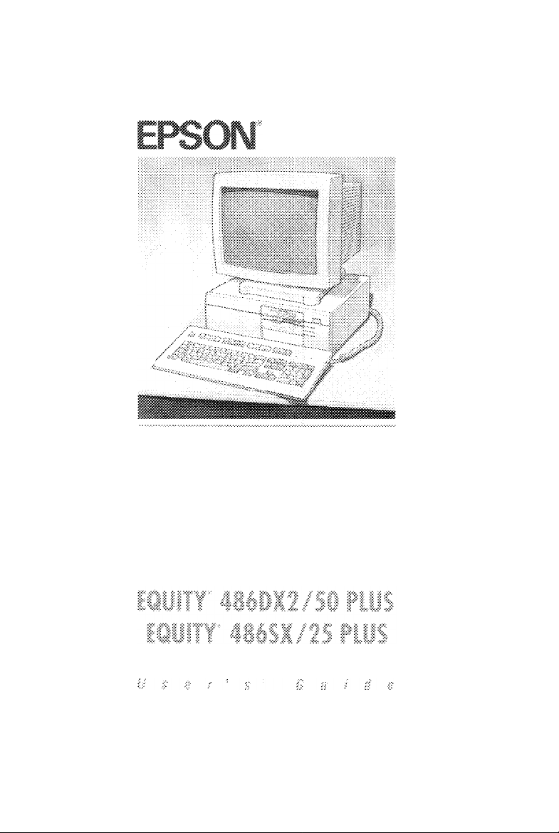
Chapter 1
Setting Up Your System
Setting up your Epson personal computer is easy. Just follow
the eight steps in this chapter. You may want to leave this
manual’s back cover foldout open so you can refer to the
illustrations identifying the different parts.
Before you begin, make sure your computer is turned off by
pressing the power button on the right side of the front panel.
It is off when the button pops out.
Choosing a Location
7
Setting Up Your System 1-1
Page 20

Before you set up your computer, it’s important to choose a
safe, convenient location that provides the following:
A sturdy desk or table strong enough to support the weight
of your system and all of its components.
A flat, hard surface. Soft surfaces like beds and carpeted
floors attract static electricity, which can erase data on your
disks, damage the computer’s circuitry, and prevent proper
ventilation.
Good air circulation. Leave several inches of space around
the computer so air can move freely.
Moderate environmental conditions. Select a cool, dry area
and protect your computer from extremes in temperature,
humidity, dust, and smoke. Avoid direct sunlight or any
other source of heat.
Appropriate power sources. Connect all your equipment to
the appropriate power source. (See “Power Source
Requirements” in Appendix D for more information.) You
need one outlet for the computer, one for the monitor, and
additional outlets for a printer and any other peripheral
devices.
1-2
cl
No electromagnetic interference. Do not place your system
too close to any electrical device, such as a telephone, which
generates an electromagnetic field.
Setting Up Your System
Page 21
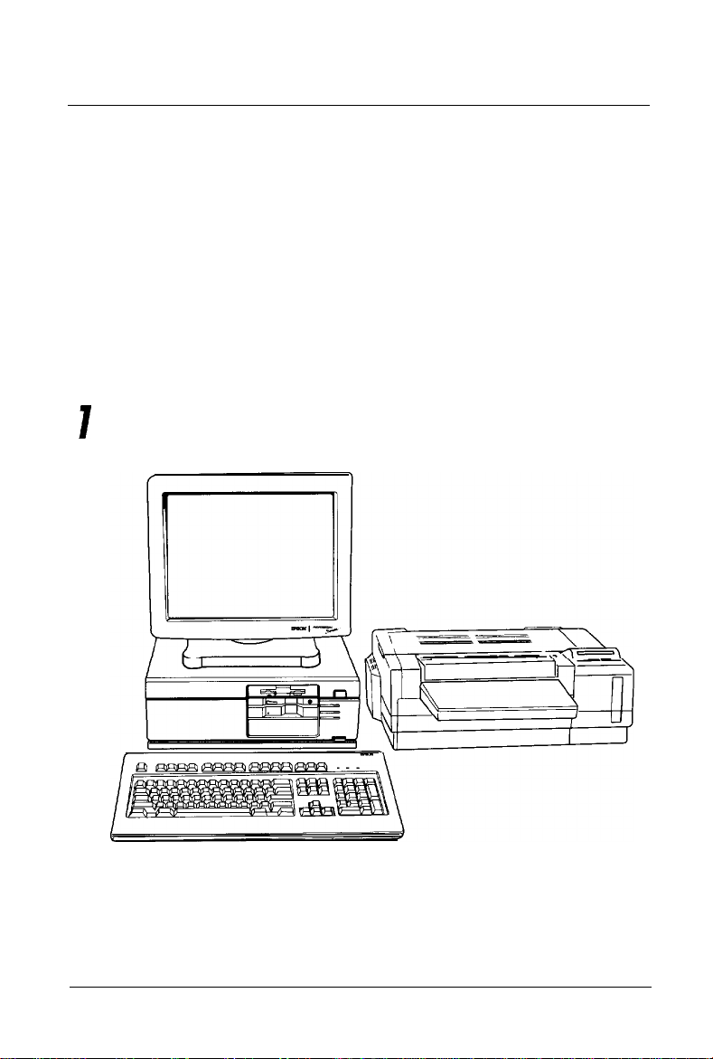
Removing the Protector Card
2
If you have a
inserted in the diskette slot at the factory to protect the drive’s
read/write heads. To remove it, either flip up the latch or press
the release button to pop the card out part way. Then pull it all
the way out.
Save any protector cards you remove; you may want to reinsert
them later, if you transport your computer.
544inch
diskette drive, a protector card has been
Connecting a Monitor
3
If you have a VGA monitor (or a multi-frequency monitor with
an analog connector), you can connect it to the computer’s
built-in VGA port. See “Using the VGA Interface,” below. If
you have any other type of monitor, skip to “Using a Display
Adapter Card,” below.
Setting Up Your System 1-3
Page 22
Using the VGA Interface
Follow these steps to connect your VGA monitor to the VGA
port on the computer:
1.
Make sure your monitor and computer are turned off.
2.
Place your monitor on top of or near the computer. For easy
access, turn the monitor and computer around so the backs
of both components are facing you.
3.
If necessary, connect the monitor cable to the monitor.
(Your monitor may have a permanently attached cable.)
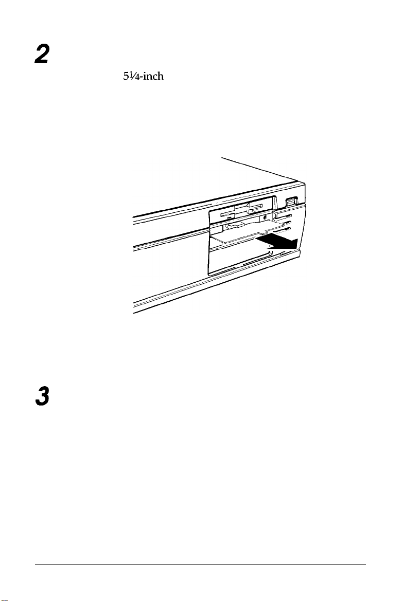
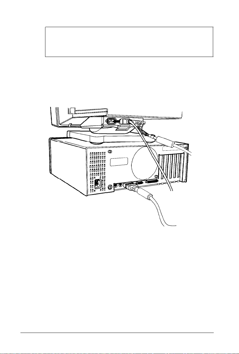
4.
Examine the connector end of the monitor cable, and position
the plug to match the orientation of the monitor port
(marked with a monitor icon). Then insert the plug into the
port, as shown below.
1-4 Setting Up Your System
Page 23
Caution
To avoid damaging the connector, take care not to bend
the pins when you insert the plug.
5.
If the connector has retaining screws, be sure to tighten them.
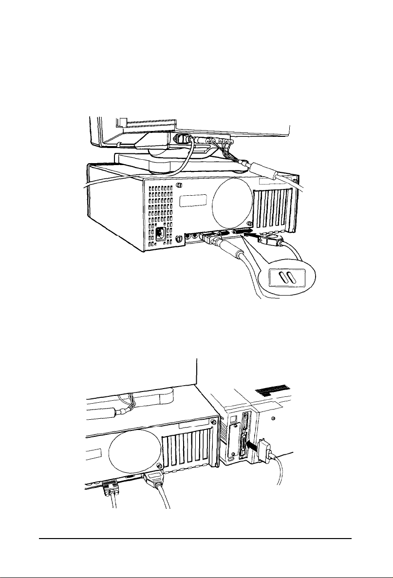
6.
Plug the monitor power cord into the monitor’s power inlet,
as shown below.
7.
Plug the other end of the power cord into a properly
grounded (earthed) electrical outlet.
Setting Up Your System
1-5
Page 24

Using a Display Adapter Card
If you are using a non-VGA monitor, you’ll need to install a
display adapter (video) card in one of the computer’s option
slots before you
have already installed the video card for you.)
If the video card is not installed, follow the instructions in
Chapter 6 to install an option card. But first, check the
following table to make sure your display adapter card and
monitor are properly matched.
Monitor/video card compatibility
Monitor
Monochrome
CGA
EGA
Monochrome or color VGA Video graphics array (VGA)
Extended VGA
can
connect the monitor. (Your dealer may
Video card
Monochrome display adapter (MDA)
Multi-mode graphics adapter (MGA)
Enhanced graphics adapter (EGA)
Hercules’ graphics card
Color graphics adapter (CGA)
Multi-mode graphics adapter (MGA)
Enhanced graphics adapter (EGA)
Enhanced graphics adapter (EGA)
Super VGA adapter
switches or jumpers on the card are set properly. For example,
you may need to change a setting to select color or
monochrome. See the documentation that came with your
monitor or video card for instructions.
If you install an EGA or VGA display adapter card or if you
install another type of card that you want to be the primary
display adapter, you must set jumper JP4 on the main system
board to disable the built-in VGA interface.
1-6
Setting
Up Your System
Page 25

If you install one or more cards, you also may need to set
jumper JP6 to tell the computer the type of monitor you are
using: monochrome or color. If you have two types of cards, set
the jumper to indicate which one is your primary monitor type.
See Chapter 6 for instructions on changing jumper settings.
Once you have installed your video card, return to this section
to connect your monitor to the computer. Follow the steps in
“Using the VGA Interface” on page 1-4, but insert your monitor
connector into the video card port instead of the built-in VGA
port.
Connecting a Printer or Other Device
4
Your computer has both parallel and serial interfaces. To
connect a printer or other peripheral device to one of these
interfaces, follow the instructions below. Epson offers a full
range of printers; ask your dealer for more information.
Using the Parallel Interface
The parallel interface on your computer is Centronics®
compatible and uses a DB-25S connector.
To connect your printer and computer, you need an IBM
compatible printer cable. If you are not sure which one you
need, check with your Epson dealer.
Once you have the correct printer cable, follow these steps:
Make sure the printer and your computer are turned off.
1.
Place the printer next to the computer with the back panels
2.
of both components facing you.
Setting Up Your System
1-7
Page 26
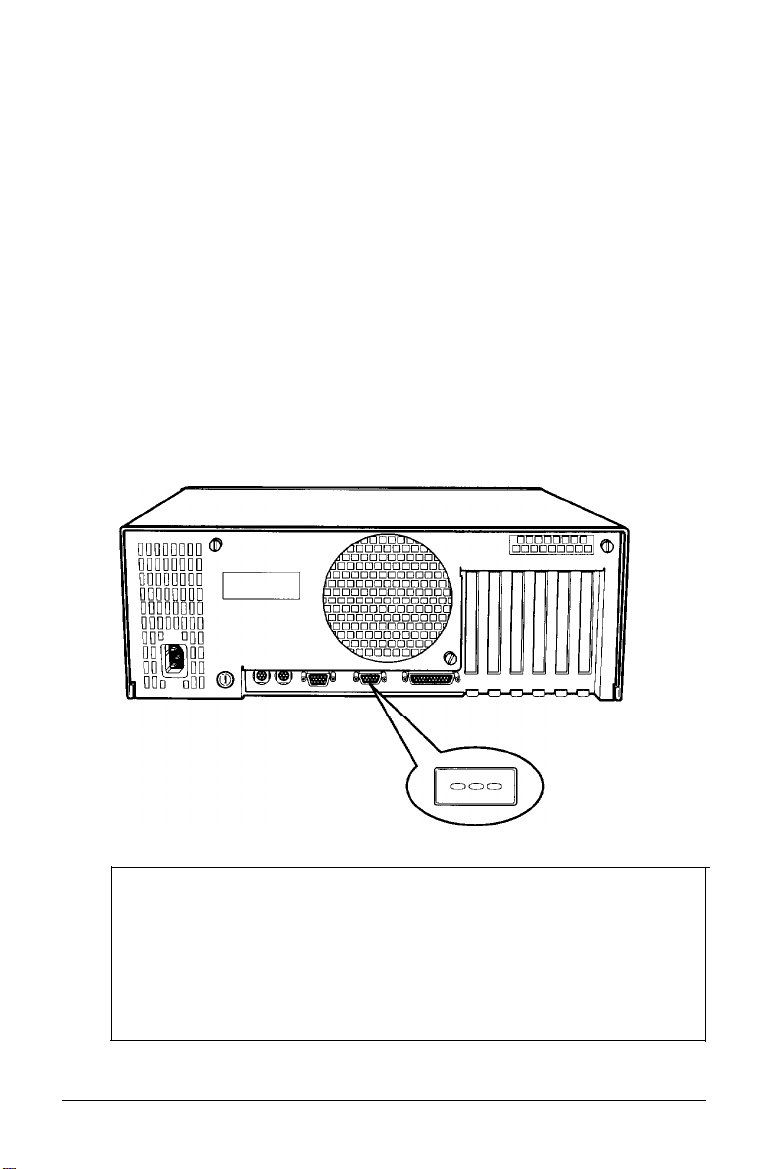
3.
One end of the printer cable has a 25-pin, D-shell connector.
Position the plug to match the orientation of the parallel
port (marked with a special icon); then insert it into the
port, as shown below. If the plug has retaining screws, be
sure to tighten them.
4.
Connect the other end of the cable to the printer, as shown
below. To secure the cable, squeeze the clips at each side of
the printer port.
1-8
Setting Up Your System
Page 27
5.
Plug the printer’s power cord into a properly grounded
(earthed) electrical outlet.
Using the Serial Interface
If you have a printer, a modem, or other peripheral device with
a serial interface, you can connect it to the serial (RS-232C) port
on the back of the computer.
The serial port has a DB-9P connector, so be sure you have a
compatible cable. To connect a serial device, follow the same
steps as above for connecting a parallel device, but insert the
connector into the serial port, marked with a special icon, as
shown below.
Note
Additional steps may be necessary to set up the serial port so
it functions properly. If you are using the port for a printer,
you need to direct printer output to the serial port, not the
parallel port. To do this, you can use the MS-DOS MODE or
SETMODE command. See your MS-DOS manual for details.
Setting Up Your System
1-9
Page 28
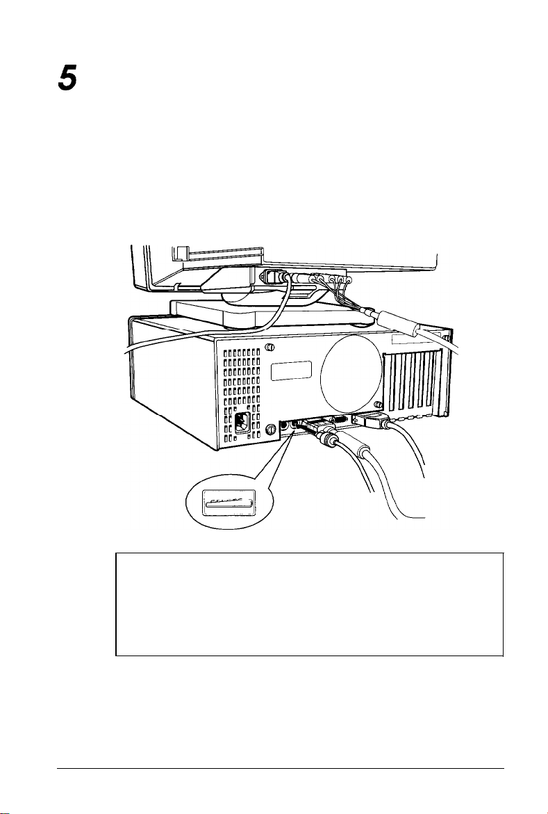
Connecting the Keyboard
5
Follow these steps to connect the keyboard:
1.
Make sure the computer is turned off.
2.
Hold the keyboard cable connector so the arrow indicator on
the housing faces up. Insert the connector into the port
marked with the keyboard icon, as shown below.
1-10
Caution
Although the connectors and ports for the keyboard and
mouse are physically identical, they cannot be used
interchangeably. Be sure to plug the keyboard only into
the keyboard port.
Setting Up Your System
Page 29
3.
You can raise the keyboard by adjusting the legs on the
bottom. To change the angle of the keyboard, turn it over
and flip each leg upward until it locks into place, as shown
below.
recessed tab
If you want to lower the keyboard, press down on the
recessed tab (labelled L or R) and lower the leg into the slot.
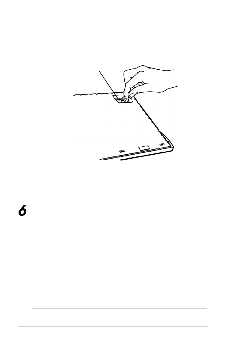
Connecting the Mouse
6
Your computer has an auxiliary port for an IBM PS/2
compatible mouse that uses a miniature DIN (6-pin) connector.
If your mouse has this type of connector, you can connect it to
the built-in port on your computer.
Note
If you have a mouse that requires a different interface port,
you can connect it to the built-in serial port or install an
option card to provide the interface. You also need to change
the setting of jumper JP7 inside the computer. See Chapter 6
for instructions or ask your dealer for assistance.
Setting Up Your System 1-11
Page 30
Follow these steps to connect a mouse:
1.
Make sure the computer is turned off.
2.
Hold the mouse connector so it is oriented properly with its
port (marked with a mouse icon). Insert the connector as
shown below.
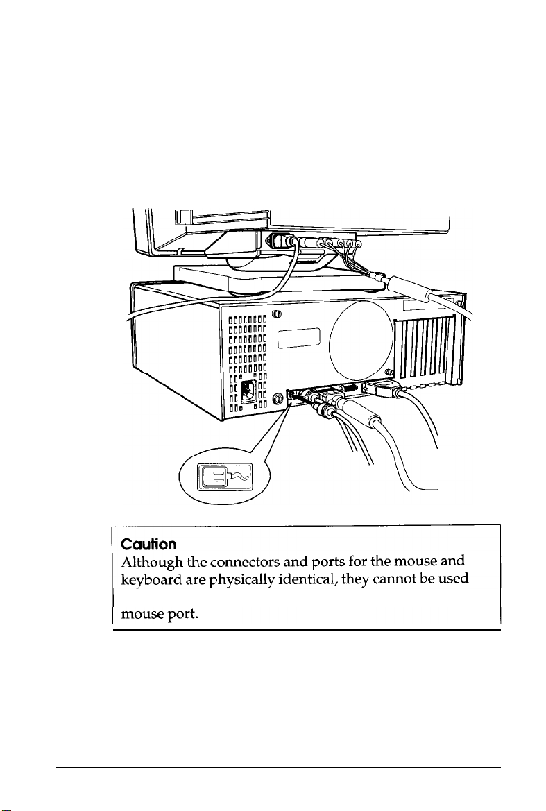
interchangeably. Be sure to plug the mouse only into the
3.
After you connect a mouse, you may need to add
commands to your MS-DOS CONFIG.SYS file to enable
your computer to use it. See your MS-DOS and mouse
manuals for instructions.
1-12 Setting Up Your System
Page 31

7
Connecting the Power Cord
Follow these steps to connect the power cord:
1.
Plug the power cord into the AC power inlet on the back
panel, as shown below.
WARNING
To avoid an electric shock, be sure to plug the cord into
the computer before plugging it into the electrical outlet.
2.
Plug the other end of the power cord into a properly
grounded (earthed) electrical outlet.
Setting Up Your System
1-23
Page 32

Turning On the Computer
8
After you set up your system, you’re ready to turn on the
power. But first, read the following safety rules to avoid
accidentally damaging your computer or injuring yourself:
Do not connect or disconnect any peripheral device or
power cables when the computer’s power is on.
Never turn on the computer with a protector card in a
diskette drive.
Never turn off or reset your computer while a disk drive
light is on. This can destroy data stored on the disk.
Always wait at least five seconds after you turn off the
power before you turn it on again. This allows the
computer to clear and reset its memory.
Do not leave a beverage on top of or next to your computer
or any of its components. Spilled liquid can damage the
circuitry of your equipment.
Always turn off the power, disconnect the computer’s
power cord, and wait 30 seconds before you remove the
cover. Only remove the cover to access internal devices.
Follow these steps to turn on your system:
1.
Make sure the power cord is plugged into the power inlet
on the back panel of the computer and into a properly
grounded (earthed) electrical outlet.
2.
Place your system components in an arrangement that suits
you. (See step 1, “Choosing a Location,” for a typical setup.)
3.
Turn on the monitor, printer, and any other peripheral
devices connected to the computer.
1-14
Setting Up Your System
Page 33

To turn on the computer, press the power button located on
4.
the right side of the front panel, as shown below.
power
The power indicator below the button lights up. After a few
seconds, the computer starts to perform a diagnostic self testa series of checks it completes each time you turn it on to make
sure everything is working correctly.
Note
If you or your dealer have made a major change to your
system, such as adding a disk drive, you may need to wait a
few minutes for your computer to complete power-on
diagnostics the first time you turn it on.
When the system has successfully completed its self test, you
see a prompt to insert a system diskette. (Do not insert a
diskette at this point.)
If necessary, use the controls on your monitor to adjust the
brightness and contrast until characters on the screen are clear
and at a comfortable level of intensity. If your monitor has
horizontal and vertical hold controls, you may need to use
them to stabilize the display.
Setting Up Your System
1-15
Page 34

Turning Off the Computer
When you are ready to turn off your system, reverse the
sequence of steps you followed to turn it on. Turn off the
computer first, then turn off the monitor and any peripheral
devices.
Now go on to Chapter 2 and follow the instructions to run the
Setup program.
1-16
Setting Up Your System
Page 35

Chapter 2
Running the Setup Program
The first time you use your computer, you need to run the
Setup program on the Reference diskette to define the
computer’s configuration. You may also need to run it again
later, if you change the configuration.
The Setup program automatically configures parts of your
system and lets you set (or change) the following for your
computer:
Q
Display adapter type
U
Power-on password
Ll
Extended memory caching
Q
Processor speed
Cl
Keyboard and speaker options
Ll
Real-time clock’s time and date
Lt
Hard disk drive configuration
Cl
Diskette drive type(s)
Ci
Serial and parallel port settings.
The configuration you define with Setup is stored in the
computer’s CMOS RAM, which is backed up by a battery.
Whenever you turn on the computer, it searches the CMOS
RAM for the correct installation information. If the computer
discovers a difference between the information in the CMOS
RAM and its actual configuration, it prompts you to run the
Setup program.
Running the Setup Program
2-1
Page 36

Automatic Configuration
Your computer automatically defines your system’s memory
configuration and recognizes whether the CPU chip contains a
math coprocessor. It also detects and configures most of the
devices you have installed in your system. For this reason, you
may not need to change any of the default settings in the Setup
program. However, you should check each of the options on
the Setup menu to verify that the settings are correct for your
configuration.
The computer automatically configures the 4MB of memory
that comes with your system as 640KB of base memory and
3072KB of extended memory. If you install even more memory,
Setup configures it as extended memory also.
Note
To run certain application programs, you may need to
reduce the amount of base memory from 640KB to 512KB or
256KB. Check the documentation that came with your
software to see if this is necessary. If you do need to change
the amount of base memory, you must set jumpers on the
computer’s main system board. See “Changing the Jumper
Settings” in Chapter 6 for instructions.
Starting the Setup Program
Follow these steps to start the Setup program:
1.
Make sure your computer is turned off.
2.
Insert the Reference diskette in drive A. (If you have a
2-2
3%inch
If you have a
diskette in the drive after you insert it.)
Running the Setup Program
drive, the diskette clicks into place automatically.
5V4-inch
drive, press the button to secure the
Page 37

3.
Turn on your system. (Remember to turn on your monitor
and any peripheral devices before you turn on the
computer.) The screen displays the Operation Menu:
OPERATION MENU
1-
Setup
2
- Format hard disk
System diagnostics
34
- Prepare hard disk for moving
- Exit to DOS for more utilities
0
If an error message appears when you turn on the
computer,
4.
The Setup option is highlighted. To select it, press
see “Continuing From an Error Message,” below.
The screen displays the main Setup menu:
Exit
Display
Password
Cache memory
Processor speed
Keyboard/Sound
Real-time clock
Hard disk drive
Diskette drive
Serial/Parallel
CEnter
Running the Setup Program 2-3
Page 38

Continuing From an Error Message
If your computer has never been set up, you may see an error
message, such as the following:
162 - System options not set
(Run SETUP in REFERENCE DISK)
(Resume = "F1" key)
If you see an error message like this one, follow these steps:
1.
Press
I.
The computer beeps and the screen displays a
message, such as the following:
Error(s) detected
l
Incorrect configuration
Set default value ? ( Y / N )
The error message next to the diamond indicates the
condition causing the error. There may be more than one
error listed in the message. Here are some of the error
messages you may see:
Time is invalid
HDD and/or HDC failed initialization
Memory size is incorrect, correction made
Cacheable range is adjusted
Incorrect configuration
Checksum is incorrect
HDD is incorrect
Some errors, such as Time is invalid, do not allow you
to set a default value, so the screen does not display the
Set default value prompt. If you see one of these
errors, press
menu so you can enter a new setting.
2-4 Running the Setup Program
I;
the screen displays the main Setup
Page 39

2.
Be sure
Y
is highlighted and press IEnter The Setup
program changes the setting that caused the error to one
that is more likely to match your configuration. The screen
displays the main Setup
menu:
Exit
Display
Password
Cache memory
Processor speed
Keyboard/Sound
Real-time clock
Hard disk drive
Diskette drive
Serial/Parallel
You should check all the settings in the Setup program to
make sure they are correct for your system. The default
value for the setting that caused the error may not be the
correct one for your configuration.
Note
If you choose N or press m instead of selecting Y to
set a default value, the Setup program does not change
the setting that caused the error and the screen displays
the main Setup menu. Be sure to correct this setting
before you exit Setup.
Running the Setup Program 2-5
Page 40

Moving the Cursor Block
Use 1 and 1‘ to move the cursor block (the highlighted bar)
through the options on the main Setup menu. After you
highlight the option you want, press [Enter to select it.
Note
If the arrow keys on the numeric keypad do not appear to
work, num lock mode may be enabled (turned on). If the
Num Lock
is lit, press
keys on the numeric keypad. If you need to enter numbers
while using the Setup program and you want to use the
numeric keypad, press
Follow the instructions in the rest of this chapter to use the
Setup program to define your computer’s configuration.
indicator in the upper right corner of the keyboard
1-1
once to turn it off and enable the arrow
[G]
to turn it back on.
Setting the Display Adapter Type
The Setup program can usually detect the exact type of display
adapter you are using with your computer. If you have
connected a VGA monitor to the built-in VGA port, the Setup
program automatically sets the display adapter type. (With
this option you select the type of display adapter you are
using-not the type of monitor.) If you have installed a display
adapter card-or you just want to check the display adapter
setting-follow these steps.
2-6 Running the Setup Program
Page 41

Note
If you have installed an EGA or VGA display adapter card,
or another type of card that you want to be the primary
display adapter, you must set jumper JP4 on the main
system board to disable the built-in VGA interface.
If you have installed one or more video cards, you also may
need to set jumper JP6 to tell the computer the type of
monitor you are using: either monochrome or color. If you
have two types of cards, set the jumper to indicate which one
is your primary monitor type. See Chapter 6 for instructions
on changing jumper settings.
1.
At the main Setup menu, highlight
Display.
A submenu
appears identifying the current display adapter type, such
as the following:
VGA
If the display adapter type is correct for your system, you
can skip the rest of this section.
2.
To change the display adapter setting, press (Enter. The
cursor block moves into the submenu and you see an
additional menu on the right side:
CGA
CGA
40 column
80 column
Monochrome 80 column
EGA,MCGA,VGA or other
Running the Setup Program
2-7
Page 42

3.
Press
m
to move the cursor block into this submenu
and then use I’ or 1 to highlight the option that matches
your display adapter type. If you are not sure which one
to choose, follow these guidelines:
tl
If you are using the built-in VGA adapter or have
installed a VGA, EGA, or MCGA card, select EGA,
MCGA,VGA or other.
tl
If you have a color graphics adapter (CGA) or a
multi-mode graphics adapter (MGA) attached to an
RGB (color) monitor, select CGA 80 column. (Also set
the color/mono switch on the MGA card to color.)
LI
If you have a composite color monitor, such as a
color television with a video input, try selecting
CGA 80 column. If the resulting resolution is poor,
run Setup again and select CGA 40
tl
If you have a monochrome display adapter (MDA), an
column.
MGA, or a Hercules MGA attached to a monochrome
monitor, choose Monochrome 80 column. (Also set
the color/mono switch on the MGA card to mono.)
2-8
tl
If you have any other combination of monitor and
display adapter card, select EGA, MCGA, VGA
other.
In addition, consult the documentation
or
supplied with your display adapter card.
Note
If you have two different display adapters, select the
setting for the one you want to be your primary display
adapter. The other one is your secondary adapter. A
message appears at power-on telling you whether you
are currently using your primary or secondary adapter.
Running the Setup Program
Page 43

4.
After you highlight the appropriate display adapter type,
press IEnter The screen displays your new setting.
5. Highlight
return to the main Setup menu.
*** SAVE SETTING *** and press
CEnter]
Setting the Power-on Password
A power-on password is an optional feature that lets you
control who can access your system. If you do not want to set a
password, skip this section.
Once you set a power-on password, you must enter it at the
key prompt ( h ) every time you turn on or reset your
computer. If you do not enter it correctly, you cannot access
your system.
If you want to use your computer as a network server, you can
set your password to operate in network server mode. (See
“Using Your Computer as a Network Server” in Chapter 4 for
more information.)
Follow these steps to set a power-on password and turn on
network server mode (if necessary):
1.
At the main Setup menu, highlight
submenu appears:
Password.
This
to
Power-on password
Network server mode OFF
2.
Press IEnter The cursor block moves to
password.
3.
Press IEnter The cursor block moves to an empty box.
Running the Setup Program 2-9
Power-on
Page 44

Note
If a password already exists, this message appears:
Power-on password already installed
The Setup program does not allow you to enter a new
password if you have already set one. However, you can
easily change or delete the current password if you
know it. See “Using a Power-on Password” in Chapter 3
for instructions.
4.
To enter a password, type any combination of characters
(including letters, numbers, and blank spaces) up to a total
of seven characters. You can use the backspace key to delete
mistakes.
Do not use characters requiring the m key, such as $,
or * in your password. The computer does not recognize
the
m
key when you use your password to access the
system.
Caution
Be sure to remember the password you enter or write it
down and keep it in a safe place. If you cannot
remember your password, you will not be able to access
the computer the next time you turn it on.
If you want to return to the password submenu without
saving any changes, press
5.
After you enter a password, press
I.
[Enter]
to return to the
password submenu.
@,
2-10
Running the Setup Program
Page 45

6.
If you want to change the network server mode setting,
highlight Network server mode. To turn network
server mode on or off, press
You must set a power-on password to turn on network
server mode. If you did not yet enter a password, this
message appears:
Set a power-on password first
To enter a password, highlight Power-on password and
follow steps 3 through 5 above.
7.
After you enter a password and turn network server mode
on or off, highlight
press
w
to return to the main Setup menu.
Note
If you forget your password, there is a way to disable the
password function. See “Password Problems” in Appendix B
for instructions.
**** SAVE SETTINGS ****and
w).
Setting the Extended Memory Caching
Extended memory caching allows your system to work much
faster. When you cache portions of memory, the computer
copies information from that memory into a high-speed cache
buffer, where it can find information faster.
Note
Caching is active only when your computer is operating at
high speed.
Running the Setup Program
2-11
Page 46

Your computer automatically enables memory caching for the
640KB of base memory. For the memory above 1MB, the Setup
program allows you to turn extended memory caching on or
off. The default setting is on for all the extended memory
currently installed in your system from 1MB up to the
maximum.
Most of the time, you should cache all of your extended
memory to maximize the performance of your 32-bit computer.
However, if you install an optional memory card that “shares”
memory with any of your other system memory, you should
turn caching off in memory areas that are shared. See the
manual that came with your memory card to see if this is
necessary.
To check or change the extended memory cache setting, follow
these steps:
1.
At the main Setup menu, highlight
Cache memory.
You
see the following cache memory table:
Extended memory caching
6 7 8 9 10 11 12 13 14 15MB+
The table indicates the range of extended memory currently
installed in your system. You see
three areas because your computer comes with 4MB of
memory and the extended memory area from 1MB to 4MB
can be cached. If you installed additional memory, you see
ON
or
OFF
for each additional megabyte of memory you
have installed. The shaded areas indicate ranges of memory
that are not installed.
If your extended memory cache setting is correct, you can
skip the rest of this section.
2-12 Running the Setup Program
ON
or
OFF
in the first
Page 47

2.
To change the setting, press
m.
The cursor block
moves to Extended memory caching.
3.
Press
m
again. The cursor block moves to the first
range in the cache table. To change the setting for the first
range from
4.
If you installed memory above 4MB, press + three times to
ON to OFF or vice
versa, press (Enter.
move the cursor block to the 4MB to 5MB range. Press
m
to change the setting from
ON
to
OFF
,
if necessary.
Then press + or t to move to the other ranges and press
IEnter as necessary, to change the settings.
5.
When you are finished, press 1‘ to move the cursor block to
the submenu.
6.
Highlight * ** SAVE SETTING ** * and press
w
return to the Setup menu.
Setting the Processor Speed
Your computer’s processor can operate at two speeds: high or
low. High speed is 25 MHz or 50 MHz (depending on your
model) and low speed simulates 8 MHz. The processor is set to
operate at high speed (where it can access memory faster)
unless you change it to low or set the speed to change
automatically (when necessary).
to
When the computer is running at high speed, the
TURBO
indicator on the front panel is illuminated.
You should use high speed for almost everything you do unless
you are using an application program that requires a slower
speed. Some programs (especially older ones) have specific
timing requirements when accessing diskettes. Check your
application program manual.
Running the Setup Program
2-13
Page 48

You can also set the processor to change its speed
automatically. This enables the computer to switch to low
speed whenever it needs to access a diskette drive, but run at
high speed for all other operations.
Note
You may not want to use the automatic setting for certain
copy-protected programs. See “Changing the Processor
Speed” in Chapter 4 for more information.
In addition to selecting the default operating speed through
the Setup program, you can change the speed temporarily by
entering a keyboard command or running the ESPEED
program. See “Changing the Processor Speed” in Chapter 4
for details.
Follow these steps to set your processor speed:
1.
At the main Setup menu, highlight Processor speed.
The current status appears:
Speed: High
If the displayed setting is correct, skip the rest of this
section.
2.
To change the processor speed, press IEnter The cursor
moves into the submenu and you see another menu:
High
Automatic
Low
2-14 Running the Setup Program
Page 49

3.
Press
[Enter]
to move the cursor block into the option
menu.
4.
Use ? or 1 to highlight the speed you want and press
IEnter
5. Highlight ** SAVE SETTING ** and press
to the main Setup menu.
m
to return
Setting the Keyboard and Speaker Options
The
Keyboard/Sound
features:
Ci
Speaker
tl
Initial num lock mode
Cl
Keyboard repeat rate.
Your computer has a built-in speaker that beeps when you
perform certain operations. The default setting is
since it serves a useful purpose in many applications; however,
you may prefer to disable the speaker.
The
Initial num lock
lock is on or off when you turn on your computer. When num
lock mode is on, you can use the numeric keys on the keypad to
enter numbers.
option lets you control these three
Enabled
option determines whether num
(on)
To turn num lock mode off, just press
light on the keyboard goes out and the feature is disabled until
you turn the computer off or until you press
next time you turn on your computer, num lock returns to the
setting you selected in the Setup program.
IsLock.
Running
the
The
[-Lock
Setup
Num Lock
again. The
Program
2-15
Page 50

Note
If you are using the keyboard that came with your computer
(or another IBM AT compatible keyboard), the default
setting for the initial num lock setting is
ON.
If you are using
a keyboard that has 83 or 84 keys, the initial num lock
default setting is
OFF.
The keyboard repeat rate option lets you change the speed at
which your keyboard repeats a character when you hold down
a key. The default setting is
Normal,
but you can make the rate
faster or slower.
Follow these steps to check or change the keyboard and speaker
options:
1.
At the main Setup menu, highlight
Keyboard/Sound.
The
current settings appear:
Speaker
Initial num lock
KB repeat rate
If the displayed settings are appropriate for you, skip the
rest of this section.
2.
To change any of the settings, press I. The cursor
block moves into the submenu and the
highlighted.
3.
To enable or disable the speaker (turn it on or off), press
IEnter
4.
To turn the initial num lock setting on or off, highlight
Initial num lock
2-16 Running the Setup Program
Enabled
Normal
and press
ON
m).
Speaker
option is
Page 51

5.
To change the keyboard repeat rate, highlight
KB repeat
Slow
Normal
Fast
6.
Press
7.
Use ? or 1 to highlight the speed you want and press
IEnter
rate.
m
to move the cursor block into the menu.
You see the following option menu:
8. Highlight
return to the main Setup menu.
*** SAVE SETTINGS *** and press
@@
Setting the Real-time Clock
The real-time clock in your computer continuously tracks the
time and date-even when the computer is turned off. The first
time you run Setup, use the Real-time
the time and date. You may need to use this option again later
to adjust your clock for daylight savings time. The computer
automatically changes the date for leap years.
You can also change the real-time clock’s time and date with
the MS-DOS TIME and DATE commands. See your MS-DOS
clock
option to set
to
Running the Setup Program
2-17
Page 52

Follow these steps to set the real-time clock:
1.
At the main menu, highlight Real-time
clock.
If the
time and date have been previously set, the current settings
appear:
Time
Date
09:16:52
03-29-1992
If the time and date are correct, you can skip the rest of this
section.
If the time and date are incorrect, go to step 2 below.
If the time and date have never been set, the submenu
contains a template for you to fill in:
Time
Date
2.
Press
m
3.
To set or change the time, press m again. You see this
xx:xx:xx
xx-xx-xxxx
to move the cursor block into the submenu.
template:
hh:mm:ss
(“hh” stands for hours, “mm” stands for minutes, and “ss”
stands for seconds.)
2-18
4.
Using a 24-hour clock, enter the time in the exact format
shown in the box. Type two digits for each part; the Setup
program automatically inserts the colons (:). For example,
to set the time to 1:30 p.m., you would type the following:
133000
Running the Setup Program
Page 53

You can use the backspace key to make corrections. When
the time is correct, press [Enter. If you enter an invalid
time-for example, a number greater than 23 for the hours
or greater than 59 for the minutes or seconds-the
computer ignores your entry. Try again.
5.
To set or change the date, highlight Date and press IEnter
You see this template:
mm-dd-yyyy
-
(“mm” stands for month, “dd” stands for day, and “yyyy”
stands for year.)
6.
Enter the date in the exact format shown in the box. Use
two digits for the month and day and four digits for the
year; the Setup program automatically inserts the hyphens
(-). For example, to set the date for March 29,1992, you
would type the following:
03291992
You can use the backspace key to make corrections. When
the date is correct, press IEnter If you enter an invalid
date-for example, a number greater than 12 for the month
or greater than the number of days in that month-the
computer ignores your entry. Try again.
7.
Press ? once or twice to return to the main Setup menu.
Note
The Setup program automatically saves the time and date
when you press
m
after typing each one. If you then exit
the Setup program without saving your changes, the new
time and date still take effect.
Running the Setup Program
2-19
Page 54

Setting the Hard Disk Drive Configuration
If your computer came with a factory-installed hard disk, your
hard disk configuration has already been set and you can skip
this section.
If you installed or removed a hard disk, follow these steps to set
the computer’s hard disk configuration:
1.
At the main menu, highlight
current settings appear, such as the following:
Hard disk drive.
Your
Drive 1:
Drive 2:
The Type number indicates the type of hard disk installed
in your computer. See your hard disk documentation for
the correct drive type number or for a list of the drive’s
parameters which you can use to identify the drive type
number. Then consult the Hard disk drive types table on
page 2-24 for a list of the types you can use in your
computer.
The None following Drive 2 : indicates that there is no
second hard disk.
If the displayed settings match your hard disk configuration,
skip the rest of this section.
If a setting is incorrect, or if you want more details about
your hard disk configuration, go to step 2.
Type 34
None
2-20 Running the Setup Program
Page 55

2.
Press IEnter You see a menu such as the following:
Drive 1: Type 34
Number of cylinders
Nunher of heads
Number of sectors
Precomp.
Landing zone
Total capacity (MB)
cylinder OFFFF Precomp. cylinder
723
13
51
722
234.06
Drive 2:
Number of cylinders
Number of heads
Number of sectors
Landing zone
Total capacity (MB)
None
The menu lists the settings you can change for each
drive: the number of cylinders, the number of read/write
heads, the number of sectors, the precompensation
cylinder, and the landing zone (the cylinder on which you
park the heads when moving the computer). It also
displays the total storage capacity in megabytes.
3.
If you want to change the settings for drive 1 (which is
drive C on most computers), press
Drive 1:.
press
4.
Press
If you want to change the settings for drive 2,
m
and then + to highlight Drive
m
again. You see this submenu:
IEnter]
to highlight
2:.
None
Type 34
User defined
Running the Setup Program
2-21
Page 56

5.
If you have disconnected the drive or if the drive does not
exist, highlight None and press
[Enter.
All the drive settings
revert to 0. Go to step 8.
If your hard disk matches one of the drive types listed in
the Hard disk drive types table, go to step 6.
If your hard disk does not match one of the drive types
listed in the Hard disk drive types table, go to step 7.
6.
Highlight
Type
and press IEnter The current type number
appears:
Type 34
Now select the drive type number that matches your hard
disk configuration in the Hard disk drive types table.
You can enter the drive type in one of two ways:
Ci
Type the drive type number and press IEnter The
screen displays the new number and settings.
CI
Use the cursor keys to scan through the drive type
numbers. This is a handy way to verify new hard disk
settings before you press
B
because the settings list
is updated as you display each new type.
After you select the appropriate drive type, press
The screen displays the hard disk settings. Go to step 8.
2-22 Running the Setup Program
[Enters.
Page 57

If your hard disk does not match one of the drive types
7.
listed in the Hard disk drive types table, highlight User
defined
and press [Enter. You see the following:
Number of cylinders
000
The same parameter is highlighted on the submenu above.
Enter the correct number of cylinders and press IEnter
The information for Number of cylinders is
automatically updated on the submenu above and you see
the next parameter, Number of heads. Enter the correct
number of read/write heads for the hard disk and press
[Enter.
Follow this same procedure for each remaining item in the
settings list (the number of sectors, the precompensation
cylinder, and the landing zone).
If you enter a parameter incorrectly, press ? or L to
highlight the parameter and then enter it again.
The Setup program does not allow you to enter the total
storage capacity; it calculates the storage capacity based on
what you enter for the number of cylinders, heads, and
sectors.
After you type the landing zone number and press [Enter,
the
cursor
block returns to the Drive submenu heading.
If you want to change the hard disk type for another drive,
8.
press + or t and return to step 4.
9.
When the hard disk drive settings are correct, press 1‘ to
move the cursor block into the top submenu. Highlight
** SAVE SETTINGS ** and press
m
to save your
hard disk drive configuration.
Running the Setup Program
2-23
Page 58

Hard Disk Drive Types
The following table lists the types of hard disk drives you can
use in your computer. Check this table and the documentation
supplied with your hard disk to find the correct type number
for the hard disk drive(s) installed in your computer.
Hard disk drive types
2-24 Running the Setup Program
Page 59

Hard disk drive types (continued)
Running the Setup Program 2-25
Page 60

Hard disk drive types (continued)
l Supported in translate mode.
l * With Western Digital ESDI controller.
2-26 Running the Setup Program
Page 61

Setting the Diskette Drive Type(s)
Your system probably came with one factory-installed diskette
drive. If you added a second diskette drive or removed one,
you may need to change the diskette drive settings to match
your configuration. If you haven’t made any changes, you can
verify your drive type settings. Follow these steps:
1.
At the main menu, highlight
current settings appear:
Diskette drive. The
Drive A:
Drive B:
If the diskette drive types on the screen match your diskette
drive configuration, you can skip the rest of this section.
2.
To change a setting, press IEnter The cursor block moves into
the diskette drive submenu and you see the following:
Not
360 KB drive
720 KB drive (3.5")
1.2 MB drive
1.44 MB drive (3.5")
You also see themessage
This tells you that the light on the diskette drive currently
selected is on.
3.
If you want to change the drive A settings, make sure
Drive A: is
change the drive B settings, highlight Drive
CEnter
installed
The cursor block moves into the submenu.
1.44 MB
None
Selected drive light is ON.
highlighted and press25Enter. If you want to
B
: and press
Running the Setup Program
2-27
Page 62

4.
selected.
If you want to enter the type for another diskette drive,
return to step 3.
5.
When the diskette drive settings are correct, highlight
** SAVE SETTINGS
block returns to the main Setup menu and you see the
updated information for drives A and B.
the correct capacity for your diskette
The screen displays the type you
* * and press
I.
The cursor
Setting the Serial/Parallel Interfaces
The serial and parallel interfaces in your computer are set to act
as the primary ports. If you have not added an additional serial
or parallel port, you can skip this section.
If you install an option card with its own serial or parallel port,
you may want to designate the built-in port as secondary and
the additional port as primary. The Setup program lets you
designate ports as primary and secondary so there is no conflict
between the built-in port and the additional port. Here are
some guidelines:
Cl
If you install an option card with a port pre-set as primary
by the manufacturer, you must make the computer’s
built-in port the secondary port.
Cl
If you install an option card or peripheral device with a
port that is not pre-set, you can designate it as the primary
or secondary port.
Li
If you install two option cards with ports, designate one as
the primary port and the other as the secondary port and
disable the built-in port.
2-28 Running the Setup Program
Page 63

Follow these steps to change your built-in serial and parallel
interface settings:
1.
At the main menu, highlight Serial/Parallel. The
current settings for each port appear:
Primary
Primary
2.
Serial
Parallel
Press
m
to move the cursor block into the submenu.
You see this additional option menu:
Disabled
Primary
Secondary
If you want to change
3.
Serial is highlighted and press
the
serial port setting, be sure
IEnter
If you want to
change the parallel port setting, highlight Parallel and
press [Enter. The cursor block moves into the submenu.
4.
Use L or 1‘ to highlight the appropriate setting for the port
you selected and press IEnter The screen displays the new
setting.
Note
If you add an option card with a parallel or serial port
and highlight
a setting that
causes a conflict between
your built-in port and the port on the option card, you
see this message:
Conflict with option card
Running the Setup Program
2-29
Page 64

If you want to change the setting for the other port, return
to step 3.
5.
When the serial and parallel port settings are correct,
highlight ** * SAVE SETTINGS *** and press
The cursor block returns to the main Setup menu and you
see your updated serial and parallel interface settings.
Reviewing Your Settings
When you finish using the Setup program to define your
computer’s configuration, use ? to highlight
Setup menu and press IEnter The following Setup summary
appears on the screen:
Exit at
IEnter
the
main
2-30
Memory
Password
Display type Detected VGA
processor speed
Base memory
Extended memory
Power-on password
Network server mode
Running the Setup Program
640 KB
3072 KB
not installed
OFF
EGA,MCGA,VGA or other
High
Page 65

There are two more Setup summary screens you need to check.
To display the next screen, press
m.
You see the following:
Real-time clock
Diskette drive
Speaker
Initial num lock
Keyboard repeat rate
Serial
Parallel
Time
Date
Drive A:
Drive B:
13:40:38
03-29-1992
not installed
1.44 MB
None
Enabled
ON
Normal
Primary
Primary
If you have never set the real-time clock, the entry at the top of
the screen flashes to remind you to set the time and date. See
“Setting the Real-time Clock” on page 2-17 for instructions.
Running the Setup Program
2-31
Page 66

To view the last Setup summary screen, press m. You see
your hard disk drive configuration(s):
Hard disk drive
Drive 1:
Number of cylinders
Number of heads
Number of sectors
Precomp. cylinder
Landing zone
Total capacity (MB)
Type 34
723
13
51
OFFFF
722
234.06
Drive 2:
Number of cylinders
Number of heads
Number Of Sectors
Precomp.
Landing zone
Total capacity (MB)
None
cylinder
Check each Setup summary screen to see if all the information
is correct. You can press
or
(@@
to display the next screen. If anything is incorrect,
highlight Change settings and press
m
to display the previous screen
m.
The main
Setup menu appears and you can change the appropriate
settings.
Leaving the Setup Menu
0
0
0
0
0
.0
If you did not change any settings or you want to cancel the
changes you made, highlight
Exit without
saving at a
Setup summary screen and press IEnter The Operation Menu
appears.
2-32
Running the Setup Program
Page 67

If you want to save the settings you entered, highlight
** EXIT AND SAVE ** and press
m
at a Setup summary
screen. The Setup program stores the new settings and resets
the computer using the new configuration. If you have set a
password, you need to enter it at the key prompt. (See “Using
a Power-on Password” in Chapter 3 for instructions.) The
Operation Menu appears.
If you have just run Setup for the first time, remove the
Reference diskette from the drive and turn off your computer.
Then follow the instructions in your MS-DOS manual to install
the operating system. (If you are using a different operating
system, follow the installation instructions in that manual.)
Once you have installed MS-DOS, you should always boot the
computer from the hard disk or the MS-DOS Startup diskette
when you are finished running Setup. First remove the
Reference diskette from drive A. If you do not have a hard disk,
insert the Startup diskette. Then reset your computer to make
sure it performs all the commands in the CONFIG.SYS and
AUTOEXEC.BAT files.
If the computer displays an error message while it is starting
up, run the Setup program again and check the setting the error
message indicates. If the computer still displays an error
message after you check your Setup program settings, see
Appendix B or C, or ask your dealer for assistance.
Be sure to make a backup copy of your Reference diskette
Running the Setup Program 2-33
Page 68

Chapter 3
Using Your Computer
This chapter briefly describes the following procedures for
using your computer:
Q
Installing MS-DOS or another operating system
CI
Copying the Reference and Utility diskette files
tl
Locking the computer’s cover
Cl
Using special keys on the keyboard
CI
Stopping a command or program
tl Resetting the computer
tl
Using a power-on password
0
Preparing a hard disk for moving.
Installing MS- DOS or Another Operating System
After you connect the components of your system and run the
Setup program, you must install the operating system on your
computer. The instructions in this manual assume that you are
using MS-DOS with your computer, but you can install another
operating system, such as OS/2 or UNIX. See the documentation
that came with your operating system for instructions on
installing it.
Note
Be sure to make backup copies of your original operating
system diskettes.
Using Your Computer
3-1
Page 69

Copying the Reference and Utility Files
If you have a hard disk, you’ll probably want to copy some of
the files on your Reference and Utility diskettes to the hard disk
for convenience. This allows you to run the programs any time
without having to insert a diskette. Copy the following files
from the Reference diskette to your hard disk:
AFDD.EXE ESPEED.EXE HDSIT.COM
HDSIT.VER ROMBIOS.COM
(See Chapter 4 and Appendix B for instructions on using these
files.)
The Reference diskette also contains files for the Setup program
and the System diagnostics program. Because you should
always run these programs from the Reference diskette, do not
copy these files to your hard disk.
The Utility diskettes contain VGA drivers that allow you to
display graphics in certain high-resolution modes. If you want
to use any of these extended modes on your VGA monitor,
copy any VGA files you need to your hard disk. See the VGA
Utilities booklet for instructions.
Note
Be sure to make backup copies of your Reference and Utility
diskettes.
3-2 Using Your Computer
Page 70

Locking the Computer’s Cover
You can lock the cover onto the computer to prevent
unauthorized users from accessing its internal components.
To lock the cover, insert the key as shown on the left and turn it
clockwise. To unlock the cover, insert the key as shown on the
right and turn it counterclockwise.
Special Keys on the Keyboard
Certain keys on your keyboard serve special functions when
your computer is running MS-DOS or application programs.
These special keys are described in the table below.
Special key functions
Moves the cursor one tab to the right in normal
mode and one tab to the left in Shift mode.
Changes the letter keys from lower- to
uppercase; changes back to lowercase when
pressed again. The numeric/symbol keys on the
top row of the keyboard and the symbol keys in
the main part of the keyboard are not affected.
Produces uppercase characters or the top
symbols on the keys when used with the main
character keys. Produces lowercase characters
when the Caps Lock function is on.
Using Your Computer
3-3
Page 71

I
Purpose
Works with other keys to perform special (control)
functions, such as editing operations in MS-DOS
and various application programs.
Works with other keys to enter alternate
character codes or functions.
Moves the cursor back one space, deleting the
character to the left of the cursor.
Ends a line of keyboard input or executes a
Turns the Insert function on and off.
Deletes the character marked by the cursor.
Control cursor location,
Changes the function of the numeric/cursor keys
from entering numbers to positioning the cursor;
1
changes back when pressed again.
Cancels the current command line or operation.
Perform special functions within application
programs.
Prints the screen display on a printer.
Generates the System Request function in some
application programs (used with Alt).
Controls scrolling in some applications.
Suspends the current operation.
Terminates the current operation (when used
with
Ctrl).
I
I
The
[=I,
[G),
and
[ZLoekl]
keys work as toggles; press
the key once to turn on a function and again to turn it off. When
the function is enabled, the corresponding light in the upper
right corner of the keyboard is on.
3-4
Using Your Computer
Page 72

Stopping a Command or Program
You may sometimes need to stop a command or program while
it is running. If you have entered an MS-DOS command that
you want to stop, try one of the following commands:
Cl
Hold down the
D
Hold down the
These methods may also work in your application program.
If not, you may need to reset the computer as described below.
Caution
Do not turn off the computer to stop a program or command
because the computer erases any data you did not save.
m
key and press
[
key and press
[cl.
w.
Resetting the Computer
Occasionally, you may want to clear the computer’s current
settings or its memory without turning it off. You can do this
by resetting the computer.
For example, if an error occurs and the computer does not
respond to your keyboard entries, you can reset it to reload
your operating system and try again. However, resetting
erases any data in memory that you have not saved; so reset
only if necessary.
Caution
Do not reset the computer as a means to exit a program.
Some programs classify and store new data when you exit
them in the normal manner. If you reset the computer
without properly exiting a program, you may lose data.
Using Your Computer 3-5
Page 73

To reset the computer, the operating system must be either on
the hard disk or on a diskette in drive A; so if you do not have a
hard disk, insert the system diskette in drive A.
There are two ways to reset the computer:
Ll
If you are using MS-DOS, hold down m and
press the
and then the computer reloads MS-DOS. If it doesn’t, try
the next method.
tl
Press the
works even when the computer does not respond to your
keyboard entries.
If resetting the computer does not correct the problem, you
probably need to turn it off and on again. Remove any
diskette(s) from the diskette drive(s). Turn off the computer
and wait five seconds. If you do not have a hard disk, insert the
system diskette in drive A. Then turn on the computer.
[Delete]
key. The screen goes blank for a moment
RESET
button on the front panel. This method
[
Using a Power-on Password
and
If you set a power-on password when you ran the Setup
program, you must enter it every time you turn on or reset the
computer. Follow these steps to use your password:
1.
If you do not have a hard disk, insert your system diskette
in drive A.
2.
Turn on or reset the computer. You see this key prompt:
3.
At the key prompt, type your power-on password. The key
turns when you type a character, but the screen does not
3-6
display the characters you type. Then press
Using
Your Computer
m.
Page 74

After you type the password correctly and press
happy face character appears. Then the computer loads the
operating system and displays the command prompt.
Note
If you turned on network server mode when you ran the
Setup program, you need to use a different procedure to
enter your password. See “Using Your Computer as a
Network Server” in Chapter 4.
You have three chances to enter the correct password. After the
third incorrect try, the screen displays a zero, the keyboard
locks up, and you cannot use the computer. Reset the computer
and try to enter the correct password again.
Note
If you do not know the correct password, see “Password
Problems” in Appendix B.
ml,
Changing a Power-on Password
a
To change your power-on password, follow these steps:
1.
If you do not have a hard disk, insert your system diskette
in drive A.
2.
Turn on or reset the computer. At the key prompt, enter
your current password followed by a forward slash (/) and
the new one you want to use. For example, if your current
password is 123 and you want to change it to ABC, type:
123/ABC
The screen does not display what you type.
Using Your Computer
3-7
Page 75

Do not use characters requiring the m key, such as $, @,
or *, in your new password.
3.
Press IEnter A happy face character appears and then the
computer loads the operating system.
Deleting a Power-on Password
To delete your power-on password, follow these steps:
1.
If you do not have a hard disk, insert your system diskette
in drive A.
2.
Turn on or reset the computer. At the key prompt, enter
your current password followed by a forward slash. For
example, if your password is 123, type:
123/
3.
Press
B.
A happy face character appears and then the
computer loads the operating system.
The next time you turn on or reset the computer, it does not
request a password and loads the operating system
immediately.
3-8 Using Your Computer
Page 76

Preparing the Hard Disk for Moving
If you need to move your computer to a new location, you may
want to run the HDSIT program (on your Reference diskette) to
protect the hard disk during the move.
HDSIT moves (or parks) the disk drive’s read/write heads to a
region on the disk surface that does not contain data, and locks
them securely in position. This protects the hard disk from
being damaged if the computer is bumped accidentally.
Many hard disk drives, including all Epson drives, automatically
park their heads when you turn off the computer. If your hard
disk drive does not do this, or if you are not sure that it does, be
sure to run HDSIT.
Follow these steps:
1.
Exit any program you are using and make sure the MS-DOS
command prompt appears on the screen.
2.
If you copied HDSIT to your hard disk (as described at the
beginning of this chapter), type c : and press
onto the root directory of the hard disk.
(Enter]
to log
If you did not copy HDSIT to drive C, insert the Reference
diskette in drive A. Then type A : and press
onto that drive.
3.
Type the following and press [Enter:
HDSIT
You see a message on the screen as the computer locks the
heads and disables the keyboard. Remove any diskettes and
turn off the computer. You are now ready to move it to the new
location.
Using Your Computer 3-9
m
to log
Page 77

Chapter 4
Enhancing System Operations
This chapter tells you how to use the following procedures to
enhance the operation of your computer:
Ll
Using AUTOEXEC.BAT and other batch files
a
Changing the processor speed
Ll
Reassigning the diskette drives
CI
Using your computer as a network server
tl
Using expanded memory beyond 640KB
0
Using special VGA features.
Using AUTOEXEC.BAT and Other Batch Files
As you get used to using MS-DOS and your application
programs, you may find that there are commands you need to
run frequently. You can automate the execution of these
commands by listing them in a special file called a batch file.
When you type the name of the batch file and press IEnter
MS-DOS executes the commands in the file just as if you had
typed each command from the keyboard.
If you have a word processing program that can save a file as a
text-only file (sometimes called an ASCII file), you can use that
program to create a batch file. You can also use the MS-DOS
COPY or EDLIN command, or a text editor, to create the file.
Enhancing System Operations 4-1
Page 78

One batch file that you may find particularly useful is called
AUTOEXEC.BAT. Every time you turn on your computer,
MS-DOS looks for the AUTOEXEC.BAT file and automatically
executes each of the commands in the file.
When you install MS-DOS, it creates an AUTOEXEC.BAT file
for you. To modify the file or replace it with a new one, you can
use the COPY or EDLIN command, a text editor, or a word
processing program that can save a file as text-only. Be sure to
name the file AUTOEXEC.BAT and store it in the root directory
of the hard disk or diskette from which you load MS-DOS.
See your MS-DOS manual for more information about creating
and using batch files.
Changing the Processor Speed
Your computer’s processor can operate at two speeds: high and
low. High speed is 25 MHz or 50 MHz (depending on your
model) and low speed simulates an 8 MHz processor speed. At
high speed, the computer can access memory faster than at low
speed. The default setting is high speed unless you changed it
in Setup to low or to change automatically.
Note
When your computer is operating at high speed, the
light on the front panel is on. It is off when the computer is
operating at low speed.
You should use high speed for almost everything you do
because your programs will work faster. However, certain
application programs have specific timing requirements and
can run only at the slower speed. See your software manual to
determine if this is the case.
4-2 Enhancing System Operations
TURBO
Page 79

Some copy-protected programs require the computer to run at
low speed while accessing the program on a diskette. These
programs also usually require you to leave a key disk-the
diskette that contains the copy protection-in the diskette
drive. If you use a copy-protected program often, you may
want to set your processor speed to change automatically to
low speed when accessing the diskette and return to high speed
when it is finished.
Depending on the type of copy-protected program you have,
you may or may not want to set the processor to automatic
speed. Follow these guidelines:
Cl
If you are using a copy-protected program that can run
only on a diskette or that requires a key disk, try to load the
program at high speed. If this works, you do not need to set
the speed to change automatically. If you can’t load the
program on high, set the speed to change automatically.
tl
If you are using a copy-protected program that does not
require a key disk but requires a special procedure to install
it on a hard disk, set the speed to low while you are
installing the program. Then set the speed to high while
you load and run the program.
If this does not work, try installing and loading the
program at low speed and then change to high speed to run
it. Do not set the speed to change automatically.
There are three ways to change the processor speed:
tl
Run the Setup program
Cl
Enter a keyboard command
Cl
Run the ESPEED program.
Enhancing System Operations 4-3
Page 80

If you frequently use programs that require low or automatic
speed, use Setup to change the processor speed. See Chapter 2
for instructions.
If you use these programs only occasionally, you should use
the keyboard commands or the ESPEED program (described
below) to change the processor speed.
Entering Keyboard Commands
You can change the processor speed by entering one of the
following commands:
[=I
[AnI]
m
Changes the speed to high.
[F] (Aa] a
CT] [T] m
To enter these commands, hold down the m key and the
m
key and press the m, m, or m key located on the
numeric keypad.
characters on the main keyboard.
Note
You can use the commands listed above while you are
running a program. However, if the program uses one of the
same commands for another function, you cannot use it to
change the processor speed. For example, if you are running
a program that uses the
the cursor, you cannot enter
processor speed to low. Another alternative is to use the
ESPEED program, described below.
Changes the speed to low.
Changes the speed to low when the computer
accesses a diskette.
The commands do not work if you use the
(xl [T] a
[F] IT] a
command to move
to change the
4-4
Enhancing System Operations
Page 81

The speed setting remains in effect until you press the
RESET
button or turn off the computer, or until you change it again
using the Setup program, another keyboard command, or the
ESPEED program, described below.
Using the ESPEED Program
ESPEED provides an easy way to change the processor speed if
your application program does not recognize the m key
commands or if you
a batch file.
The ESPEED program is on the Reference diskette. If you
have a hard disk drive, copy the file ESPEED.EXE from your
Reference diskette onto your hard disk-if you have not
already done so-and run the program from there. If you do
not have a hard disk, insert your Reference diskette in drive A
and log onto drive A before you enter the command to start the
program.
To run the ESPEED program, type the following at the MS-DOS
command prompt and press
want
to include the program command in
I:
ESPEED
You see the following messages:
Usage: ESPEED[/H] [/L] [/A]
/High
/Low
/Auto
These messages tell you the switches you should use to set
speed
to
high, low,
set High speed (no auto)
set Low speed (no auto)
set Auto speed
or automatic.
At the MS-DOS prompt, type
the
the ESPEED command again and include the appropriate
switch, such as the following:
ESPEED /A
Enhancing System Operations 4-5
Page 82

(This command sets the processor speed to change to low speed
automatically when the computer accesses a diskette.)
If you include the switch when you type the initial ESPEED
command, the program changes the speed without displaying
the command options.
The processor speed you set remains in effect until you change
it using the Setup program, a keyboard command, or the
ESPEED program again or until you press the
RESET
button or
turn off the computer.
Entering the ESPEED command in a batch file
You may want to run the ESPEED program by including the
command in a batch file. For example, let’s say you have a
program called SLOWDOWN which requires a slower
processor speed. You could include the following commands in
a batch file to start the SLOWDOWN program:
ESPEED /A
SLOWDOWN
You could name the batch file SLOW.BAT. Whenever you need
to run the SLOWDOWN program, insert the program diskette
into drive A. Then type
SLOW
and press IEnter The computer
changes the processor speed to automatic and starts the
program.
4-6
Enhancing System Operations
Page 83

Reassigning the Diskette Drives
If your system has two diskette drives, they are connected
inside your computer so that the top drive is A and the bottom
drive is B. Because drive A is
to load the operating system or a bootable program from a
diskette, you must insert the diskette into drive A.
the
boot drive, whenever you want
If both of your drives are the same
type-3Winch,
1.44MB
capacity, for example-you never need to reassign the drives. If
your two drives are different types, however, you may need to
change the drive letter assignments so you can boot the
computer from drive B. For example, you may have a
5V4-inch
program disk which you need to use to boot the computer. Or
you may have an application program that requires you to
leave the 5?&inch key disk in drive A while you run the
program.
For these situations, you can reverse the drive assignments to
make the top drive B and the bottom drive A. There are two
ways to do this:
tl
Insert the diskette in drive B and turn
on
the computer.
The drive automatically becomes drive A.
Cl
Run the AFDD program to reassign the drive. See “Using
the AFDD Program,
Your assignments remain in effect until you press the
” below, for instructions.
RESET
button or turn off the computer, or until you reassign the drives
to their original assignments. The reassignment remains in
effect if you reset the computer from your hard disk by
entering the
(F] [y] [E)
command.
Enhancing System Operations
4-7
Page 84

Using the AFDD Program
AFDD reverses the current diskette drive assignments and
resets the system. When you are done using the reversed drive
assignments, you can use the AFDD program again to reassign
the drives to their original configuration.
The AFDD program is provided with your system on the
Reference diskette. If you do not have a hard disk, insert your
Reference diskette in drive A and log onto drive A before you
enter the command to start the program.
If you have a hard disk drive, copy the file AFDD.EXE from the
Reference diskette onto your hard disk (if you have not already
done so); then you can run the program from there.
To run AFDD, type the following at the command prompt and
press
I:
AFDD
You see messages such as the following:
New Assign Present
Drive A:
Drive B:
(S)et and Reboot,
1.44MB <=
1.2MB <=
Any other key to abort ?
1.2MB
1.44MB
If you inserted the Reference diskette to run AFDD, remove it
now.
If you want to change the drive assignments, press
system reboots and loads the operating system, and the new
drive assignments take effect. If you do not want to change the
drive assignments, press any other key.
4-8
Enhancing System Operations
[sl.
The
Page 85

If you are running the AFDD program from a hard disk, you
can reassign the drives and reset the corn
Type the following command and press
AFDD /S
The /S switch tells the AFDD program to reset the computer,
load MS-DOS, and change the diskette drive assignments
without displaying the messages.
Note
You may want to run AFDD by including the command in a
batch file.
Using Your Computer as a Network Server
A network server is the master computer in a network and
provides storage space for the other computers connected to it.
It can also write files to and read files from the other
computers, making it the most powerful computer in the
network.
Even if no one is typing commands at the network server
keyboard, the server can process commands sent to it from
other computers. If you use your computer as the network
server, you may want to prevent unauthorized users from
entering commands at the keyboard. To provide this security,
you can enable a power-on password in network server mode
using the Setup program.
Enhancing System Operations 4-9
Page 86

If you set a power-on password but do not turn on network
server mode, you enter the password
before
the computer loads
the operating system or the network software. Once you load it,
anyone can access your system by typing commands on the
keyboard. However, if you set a password and turn on network
server mode, you can load your operating system or network
software before you enter the password. This allows other
computers in the network to access the system, but prevents
unauthorized users from entering commands at your keyboard
and using any network server access privileges.
When you boot the computer in network server mode, you do
not see the key prompt (
@IIT ),
as you would if network server
mode was turned off. The password prompt is hidden to
prevent unauthorized users from knowing that a password is
required.
You do not have to set a password in network server mode to
use your computer as a network server, but it is helpful. See
“Setting the Power-on Password” in Chapter 2 for instructions
on setting the password and enabling network server mode.
Then read the next section to use your network password.
Note
If your hard disk drive has a partition larger than 32MB, you
must use the MS-DOS SHARE command to install file
sharing and locking protection in a network environment.
See your MS-DOS manual for more information.
If you do not install SHARE, the following message flashes
on your screen after you install your networking software
and reboot your computer:
WARNING! SHARE should be loaded for large media
4-10 Enhancing System Operations
Page 87

Using a Password in Network Server Mode
When you turn on or reset the computer, it loads your
operating system or network software and you see either the
command prompt or the first screen displayed by your
network software.
Follow these steps to enter your password:
1.
Turn on or reset your computer. You do not see the key
prompt (
for you to enter the correct password.
2.
Type your password and press IEnter The screen does not
display what you type.
Now you should be able to use your computer. Press a key
such as (Enter] to see if the keyboard accepts your command.
If you entered an incorrect password, the computer does not
respond. Type the correct password, press IEnter and try using
the computer again.
Note
You cannot change or delete a power-on password in
network server mode. You must run Setup and turn off
network server mode first. See Chapter 2 for instructions.
Then you can change or delete the password as described in
Chapter 3.
@rrr
) even though the computer is now waiting
Enhancing System Operations
4-11
Page 88

Using Expanded Memory Beyond 640KB
Your computer comes with 4MB of random access memory.
MS-DOS and your application programs that run under
MS-DOS use the first 640KB of memory. You can use the
unused memory above 640KB as extended memory, or you can
convert it to expanded memory, as described below.
Expanded memory is used by application programs (such as
Lotus® 1-2-3®) that support the Lotus/Intel/Microsoft
Expanded Memory Specification (LIM 4.0 EMS). To take
advantage of expanded memory, you need to use a memory
management program to convert the computer’s extended
memory to expanded memory.
If you selected a memory management software package when
you bought your computer, you can use it with any version of
MS-DOS. Just follow the instructions included with the package.
If you are using MS-DOS version 4.01 or 5.0 and you did not
get a memory manager, you can use the MS-DOS program
EMM386.SYS or EMM386EXE (respectively) to convert your
extended memory to expanded memory. See your MS-DOS
manuals for instructions.
If you are using MS-DOS version 3.3 and you did not get a
memory manager, ask your authorized Epson dealer which
expanded memory manager program you should use.
4-12 Enhancing System Operations
Page 89

Using Special VGA Features
Your built-in VGA display adapter supports standard VGA
monitors and multi-frequency monitors with analog
connectors. The VGA adapter allows these monitors to operate
in all standard VGA modes without requiring any special
device drivers. However, if you want to use extended VGA
modes, you can install one or more of the device drivers
provided on your Utility diskettes. These drivers allow you to
use all of the capabilities of your monitor and built-in VGA
display adapter.
The device drivers provide VGA features such as these:
Resolutions of 800 x 600 or 1024 x 768 (non-interlaced)
Q
in graphics modes with 16 colors
Resolutions up to 640 x 480 in graphics modes with
Li
256
colors
132-column text mode in 16 colors
Cl
Graphics cursor movement performed by the built-in
Ll
VGA hardware.
Note
To use graphic display drivers in 800 x 600 or 1024 x 768
resolutions, you must have a multi-frequency monitor
capable of displaying these resolutions. Standard VGA
monitors cannot display them.
Enhancing System Operations
4-13
Page 90

The Utility diskettes that came with your computer contain
device drivers for various application programs, as well as
special utilities that allow you to enhance VGA performance.
See the VGA Utilities booklet for more information about VGA
device drivers and utilities.
4-14
Enhancing System Operations
Page 91

Chapter 5
Accessing Internal Components
To access your computer’s internal components, you need to
remove the cover. In some cases, you may also need to remove
the front panel and the subassembly (the metal case that holds
the drive bays). The instructions in this chapter explain how to
do these tasks:
Remove and replace the cover
Ll
Remove and replace the front panel
Ll
Remove and replace the subassembly
Ll
Perform post-installation setup procedures.
Ll
Read the following safety precautions before you begin.
Special Precautions
As you perform the procedures described in this chapter and in
Chapters 6 and 7, observe the following precautions to avoid
damaging your equipment or injuring yourself:
While this manual provides detailed instructions for
Ll
installing a variety of optional equipment, do not attempt a
procedure if you have any reservations about performing it;
ask your dealer for assistance.
Always turn off the computer, disconnect all cables to the
tl
computer and any peripheral devices, and wait at least
30 seconds before you remove the cover. First disconnect
the power cord from the electrical outlet and from the
computer’s back panel. Then disconnect all peripheral
devices, including the monitor and keyboard.
Accessing Internal Components
5-1
Page 92

0
Every time you remove the cover, be sure to ground
yourself by touching the inside of the computer’s back
panel before you touch any components inside. If you are
not properly grounded, you could conduct static electricity
and damage your components. Also, do not touch any
components except those that this manual instructs you to
touch.
Ll
When disconnecting cables from sockets on the computer’s
main system board or any devices (such as disk drives),
avoid pulling on the cable; grasp the plastic connector to
remove it from a socket.
Cl
When plugging a connector or a component into a socket,
be sure to position it correctly. Carefully align any
connector pins with the corresponding holes in the socket
before you push in the connector. Otherwise, you can
severely damage the equipment.
Li
Always replace the computer’s cover
power, or the computer may overheat.
Removing the Cover
before you
turn on the
Remove the computer’s cover to do any of the following:
tl
Change jumper settings
c3
Install or remove option cards
Cl
Install or remove single inline memory modules (SIMMs)
Q
Install or remove a math coprocessor
Li
Install or remove disk drives or other storage devices.
5-2 Accessing Internal Components
Page 93

Follow these steps to remove the cover:
1.
Turn off the computer and any peripheral devices connected
to it. Then disconnect the computer’s power cord from the
electrical outlet and from the back panel. Also disconnect
any peripheral device cables that are connected to the
computer, including the keyboard cable.
2.
Turn the computer around so you are facing the back panel.
3.
If necessary, unlock the computer’s cover. (See Chapter 3 for
instructions.)
4.
Loosen the three thumbscrews on the computer’s back panel
by turning them counterclockwise, as shown below. (The
screws disengage but don’t come all the way off.)
Accessing Internal Components
5-3
Page 94

5.
Grasp the sides of the cover (toward the front of the
computer) and pull it firmly toward you, as shown below.
Then lift it up and off the computer.
Removing the Front Panel
You must remove the computer’s front panel if you need to
install or remove a disk drive from the external drive bay or if
you need to remove the subassembly from the computer.
Follow these steps:
1.
Turn the computer so you are facing the front panel.
5-4 Accessing Internal Components
Page 95

2.
Release the six tabs securing the front panel to the computer
case, as shown below. You may want to use a flat-blade
screwdriver to release the tabs.
3.
Once these tabs are free, grasp the sides of the front panel
and pull it
straight
toward you to disengage the two tabs at
the bottom, as shown below. Be careful not to pull the panel
off at an angle; this may bend or pop off the power and
RESET
buttons. If a button pops off, carefully place it back
onto its post.
Accessing Internal Components
5-5
Page 96

Removing the Subassembly
You need to remove the subassembly only if you are installing
or removing the hard disk drive that is mounted next to the
power supply.
Follow these steps:
1.
Turn the computer so you are facing the front panel.
2.
Disconnect the power supply and drive cables from the
backs of all the drives installed in your computer, as shown
below. Note which cables are connected to which drives so
you can easily reconnect them later.
5-6 Accessing Internal Components
Page 97

3.
Open the clasp holding the power supply and drive cables to
the side of the subassembly, as shown below. Then remove
all the cables from the clasp.
4.
Grasp the back of the subassembly by the edge on its upper
left side, as shown below, and lift up the back end.
5.
Pull the subassembly forward slightly to release it from the
two pins beneath the front panel opening. Then lift it out of
the computer and place it on your work surface.
Accessing Internal Components
5-7
Page 98

Replacing the Subassembly
Follow these steps to replace the subassembly:
1.
Turn the computer so you are facing the front panel.
2.
Hold the subassembly at a slight angle and guide the front of
it down through the opening in the front of the computer,
as shown below.
3.
Fit the two holes in the lower front of the subassembly over
the two posts on the front of the computer case, as shown
above.
5-8 Accessing Internal Components
Page 99

4.
Lower the back end of the subassembly into the computer.
If necessary, fit the post beneath the back right edge of the
subassembly into the hole on the top of the power supply.
Then lower the subassembly all the way down.
5.
If necessary, connect the diskette drive cable to the FDD
socket on the main board, then connect the hard disk drive
cable to the HDD socket beside it. (These sockets are
located to the right of the memory card.)
6.
Gather the power supply and drive cables in the clasp on the
side of the subassembly. Snap the clasp shut.
Accessing Internal Components
5-9
Page 100

7.
Connect the power supply and drive cables to the backs of all
your drives, as described in Chapter 7.
Replacing the Front Panel
Follow these steps to replace the computer’s front panel:
1.
Turn the computer so you are facing its front.
2.
Align the openings in the front panel with the power button,
RESET
your computer case. Also align the front panel tabs with the
corresponding notches in the case. Then guide the front
panel straight onto the computer case, as shown below.
button, and drives that extend out from the front of
3.
Press the front panel onto
tabs into the notches on the computer case. If all the front
panel tabs do not snap into position, remove the front panel
and try again.
5-10 Accessing Internal Components
the
computer to fully insert all the
 Loading...