


30-NC
INSTALLATION & OPERATION MANUAL
MODEL NUMBERS: 30-NCP 50-SNC30P 50-TNC30P
30-NCL 50-SNC30L 50-TNC30L
30-NCG 50-SNC30G 50-TNC30G
Thank you for purchasing this product from a fine line of heating equipment.
We wish you many years of safe heating pleasure with your new heating appliance.
Save These Instructions.
NOTE: IF YOU HAVE A PROBLEM WITH THIS UNIT DO NOT RETURN IT TO
THE DEALER. CONTACT CUSTOMER SERVICE @ 1-800-245-6489.
Questions? Need Parts or Options? www.englanderstoves.com
Please Note the Following Precautionary Statements:
CAUTION: This stove must be installed in accordance with the Manufactured Home and Safety
Standard (HUD), CFR 3280, Part 24 and must comply with local building and fire
codes. Failure to follow these instructions could result in property damage, bodily
injury or even death. Keep children, furniture, fixtures and all combustibles away
from any heating appliance.
NOTE: THIS STOVE IS MOBILE HOME AND DOUBLE WIDE APPROVED (WITH OUTSIDE
AIR HOOK-UP) FOR THE PEDESTAL MODEL ONLY – NOT FOR LEG MODELS
. DO
NOT INSTALL IN A SLEEPING ROOM. THE STRUCTURAL INTEGRITY OF THE
MOBILE HOME FLOOR, WALL AND CEILING/ROOF MUST BE MAINTAINED.
CAUTION: This unit must be installed in accordance with these instructions and must comply
with local building and fire codes. Failure to do so could result in a chimney or
house fire. Keep children, furniture, fixtures, and all combustible materials away
from any heating appliance. Refer to this owner’s manual for all clearances to
combustible materials.
SAVE THIS MANUAL FOR FUTURE REFERENCE.
Read this entire manual before you install and use your new room heater. If this room
heater is not properly installed, a house fire may result. To reduce the risk of fire,
follow the installation instructions. Failure to follow instructions may result in
property damage, bodily injury, or even death.
England’s Stove Works highly recommends the use of smoke detectors and Carbon Monoxide
detectors with any hearth product, including this unit. Follow all manufacturers’ instructions
when using smoke or Carbon Monoxide detectors
.
Rev. 5/2011

2
A letter from our Technical Support Department:
Thank you
for purchasing this fine product from England’s Stove Works!
England's Stove Works was started, and is still owned by, a family that
believes strongly in a "Do It Yourself" spirit – that’s one reason you found
this product at your favorite “Do It Yourself” store.
We intentionally design and build our stoves so that any homeowner can
maintain his or her unit with basic tools, and we're always more than
happy to show you how to do the job as easily and as inexpensively as
possible.
From our free,
downloadable service sheets; to our Pellet Service Video;
to our new "wizard-style," click-through Troubleshooting guide on our
web site, we have always tried to help our customers stay "heat-ready,"
especially when oil and electricity prices continue to skyrocket.
Please look at our vast Help section on our web site and call our Customer
Service department at (800) 245-6489 if you need any help with your unit.
We are nearly always
able to help “walk you through” any repairs,
problems or questions you may have.
PLEASE NOTE
: While information obtained on our web site and through
our 800 number is always free of charge, there will be a service charge
incurred with any “on-site” repairs or maintenance that we may arrange.
Wishing you years of efficient, quality and “comfy” heating,
England’s Stove Works
Technical Support Department
www.englanderstoves.com
(800) 245-6489
IF YOU HAVE A PROBLEM WITH THIS UNIT DO NOT RETURN IT TO THE DEALER.
CONTACT CUSTOMER SERVICE at 1 (800) 245-6489.

3
CAUTION
If you have any doubt concerning your ability to complete your installation in a professional-like
manner after reading these instructions, you should obtain the services of an installer who is versed in
all aspects as to the correct and safe installation. Do not use temporary, makeshift compromises
during installation.
BEFORE INSTALLATION OF YOUR APPLIANCE
1. HOT WHILE IN OPERATION. KEEP CHILDREN, CLOTHING AND FURNITURE
AWAY. CONTACT MAY CAUSE SKIN BURNS.
2.
DO NOT BURN GARBAGE OR FLAMMABLE FLUIDS.
3.
Check with the building inspector’s office for compliance with local codes; a permit may be
required.
4.
This appliance requires a masonry or prefabricated chimney listed to ULC S629 (Canada) and
UL103HT (U.S.) sized correctly.
5.
A 6” diameter flue is required for proper performance.
6.
Always connect this unit to a chimney and NEVER vent to another room or inside a building.
7.
DO NOT connect to any duct work to which another appliance is connected, such as a
furnace.
8.
DO NOT connect this unit to a chimney flue serving another appliance.
9.
DO NOT USE CHEMICALS OR FLUIDS TO START THE FIRE.
10.
The connector pipe and chimney should be inspected periodically and cleaned if necessary.
11.
Remember the clearance distances when you place furniture or other objects within the area.
DO NOT store wood, flammable liquids or other combustible materials too close to the unit.
12. Contact your local fire authority for information on how to handle a chimney fire. Have a
clearly understood plan to handle a chimney fire. In the event of a chimney fire, turn air control
to a closed position and CALL THE FIRE DEPARTMENT.
13.
DO NOT tamper with the combustion air control beyond normal adjustment.
14.
Once the required draw is obtained, operate only with doors closed; open doors slowly when
re-fueling (this will reduce or eliminate smoke from entering the room).
15.
Visit our web site at www.englanderstoves.com for helpful information, frequently asked
questions, parts/accessory orders and more. Customer Service: (800) 245-6489.
Note on Outside Air Hookup: You can use an outside air hookup with this unit. We highly recommend it for
homes built since the more air-tight construction standards went into effect. This involves connecting a metal pip e
(usually three inches (3”) in diameter - check your stove - and the pipe can be flex or rigid) from the air inlet pipe
located on the bottom rear of the stove through your floor or wall. The outside end of this pipe should be covered
in some manner (i.e. with a screen) to keep it clear of foreign matter. Be sure to keep it above the snowdrift line
and clear of leaves and other debris. It is necessary to use this hookup if installing in a mobile home or
double-wide – See “Outside Air Connection” section of manual.
A kit is available from England’s Stove Works, Inc. designed for connecting this unit to outside
combustion air. [Part No. AC-OAK3]
4
WHY THE CORRECT FLUE SIZE IS IMPORTANT: 6”
“Draft” is the force that moves air from the appliance up through the chimney. The amount of draft in
your chimney depends on the length of the chimney, local geography, nearby obstructions, and other
factors. Too much draft may cause excessive temperatures in the appliance. An uncontrolled burn or
a glowing red part or chimney connector can indicate excessive draft. Inadequate draft may cause
back puffing into the room and “plugging” of the chimney and/or cause the appliance to leak smoke
into the room through appliance and chimney connector joints.
Today’s solid fuel appliances are much more efficient than in the past. The units are designed to give
you controlled combustion, as well as maximum heat transfer, using less fuel to do so.
The design of your new appliance is such that the exhaust “smoke” is now at lower temperatures than
in the past, therefore requiring proper chimney size to give adequate draft. If your chimney is too
large, the heater will have a difficult time raising the temperature of the flue enough to provide
adequate draft, which can cause a "smoke back," poor burn, or both.
Should you experience such problems, call in a local chimney expert.
With the door closed, the rate of burning is regulated by the amount of air allowed to enter the unit
through the air control. With experience, you will be able to set the control for heat and burning time
desired.
Attempts to achieve higher output rates that exceed heater design specifications can result in
permanent damage to the heater. The recommended wood load is level with the top of the firebricks.
Overloading may prevent sufficient air entering the heater to properly fuel the fire.
Do not tamper with the combustion air control beyond the normal adjustment capacity.
Operate this heater only with the door closed.
DO NOT OVERFIRE. If the heater or chimney connector glows, you are overfiring.
ALWAYS PROVIDE A SOURCE OF FRESH AIR INTO THE ROOM WHERE THE UNIT IS
INSTALLED. FAILURE TO DO SO MAY RESULT IN AIR STARVATION OF OTHER FUEL
BURNING APPLIANCES AND THE POSSIBLE DEVELOPMENT OF HAZARDOUS CONDITIONS.
THIS HEATER IS EXTREMELY HOT WHILE IN OPERATION. SERIOUS BURNS CAN RESULT
FROM CONTACT. CAUTION SHOULD BE OBSERVED, ESPECIALLY WHEN CHILDREN ARE
PRESENT.
5
FLUE SYSTEM
1. Existing Flue System
If you have chosen a freestanding unit, this stove is designed to connect to an existing flue system,
such as masonry or a pre-manufactured Class A flue system. If you have a masonry flue system, the
inner liner should be inspected carefully for cracks; if there is no liner in your chimney, we recommend
you install a steel liner or have one installed. If you have an existing pre-manufactured system the
inner liner should be inspected for warping or buckling. Either type chimney system should be
thoroughly cleaned before installing your new stove. We strongly recommend you have a qualified
chimney sweep clean and inspect your entire system, as the sweep can spot problems you might
overlook. The sweep in most cases can make any necessary repairs or recommend a qualified
person to do so.
It is not permissible to connect this unit to a chimney that is servicing another unit.
2. Flue Size
The proper flue size is determined by measuring the inside diameter of the flue collar on the unit.
This stove is equipped with a six inch (6”) TOP EXHAUST FLUE COLLAR. Therefore, the connector
pipe should be six inches (6”) and never less in diameter than the collar on the stove. Your unit may
require an adapter (AC-1677) which will reduce the 6” connector pipe by
1
/
8
”. This is necessary to
accommodate pipe variation from different manufacturers and maintain a good seal. The area of the
chimney liner must also be equal to or greater than the area of the flue collar on the stove. If the area
of the flue is greater than the collar, it should never be more than two and
1
/
2
(2.5) times greater.
The black connector pipe should be 24 gauge steel and sixteen inches (16.0”) from a combustible
wall or eighteen inches (18.0”) from a combustible ceiling. This clearance can be reduced by using
double wall or single wall stovepipe shields.
3. Installation of a New Flue System
Note: Flue systems and flue pipe are not furnished with the unit.
Masonry Flue: In the event that you plan to install or have a system installed, there are several
approaches that you can take. In the middle and late seventies masonry flue systems became very
popular, and today this type system is satisfactory. If you are considering a masonry system, you
should consult with your local building officials for the proper procedures on this type chimney. We
recommend you consult with and have your flue built by a licensed, bonded contractor. Most masonry
chimney systems are placed against an outside wall and extend upward beside the house. The flue
thimble is then inserted through the wall, making the connection with the stovepipe and the vertical
flue. Exercise extreme caution when drilling through the wall -- you must maintain proper clearance
between the connecting liner and any combustible material in the wall.
We also recommend you have a flue clean-out door located at least two feet (2’) below your
thimble for easy cleaning of the system. This door should be made as airtight as possible. It is the
consumer’s responsibility to ensure the chimney system is safe and in good operating condition.
The manufacturer will not be held responsible for an accident attributed to a unit connected to a faulty
chimney system.
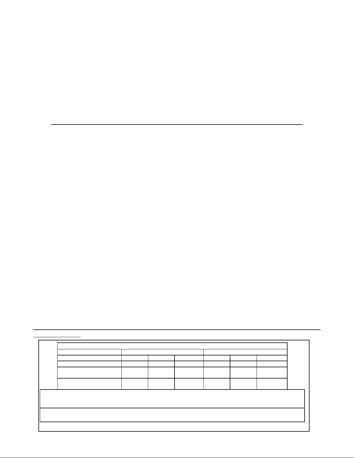
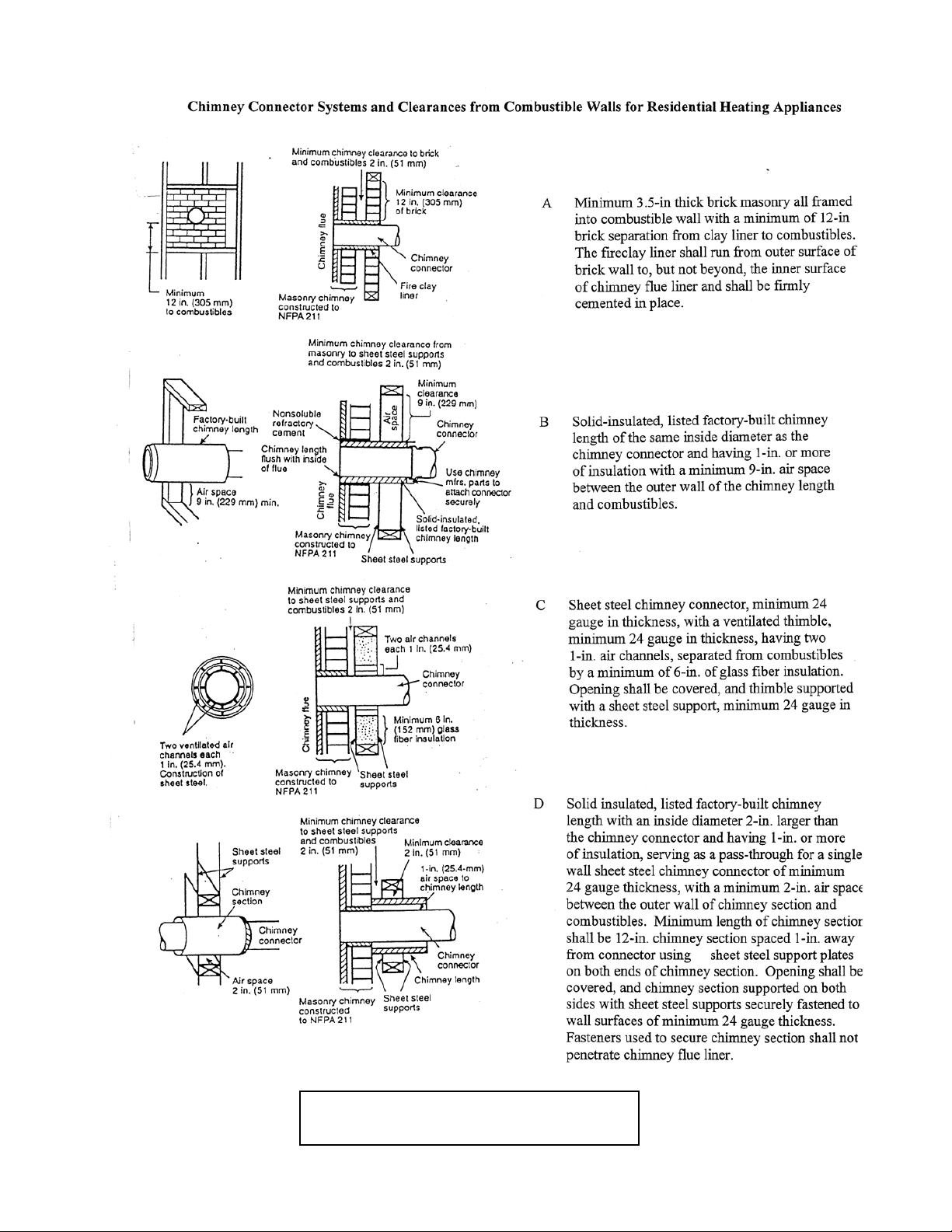
CLEARANCE TO COMBUSTIBLES (See Illustration 1)
Appliance Clearances Unprotected Surfaces Protected Surfaces (NFPA-211)
Side (A) Rear (B) Corner (D) Side (A) Rear (B) Corner (D)
No stove heat shields 20-in 14-in 15-in 12-in 12-in 12-in
Side and Rear shields, single
wall chimney connector
19-in 8-in 14-in 12-in 8-in 12-in
Side and Rear shields, double
wall connector
20-in 5-in** 15-in 12-in 5-in** 12-in
NOTE: Flue Connector to back wall (C):
1. Single wall connector with rear shield = 16”
2. Single wall connector with rear & side shields = 10”
3. Double wall connector with rear & side shields = 7”
NOTE: Flue Connector to corner (E):
1. Single wall connector with rear shield = 20.5”
2. Single wall connector with rear & side shields = 19.5”
**Please Note that the AC-16 blower requires approx. 7” if installed on the rear of the unit
6
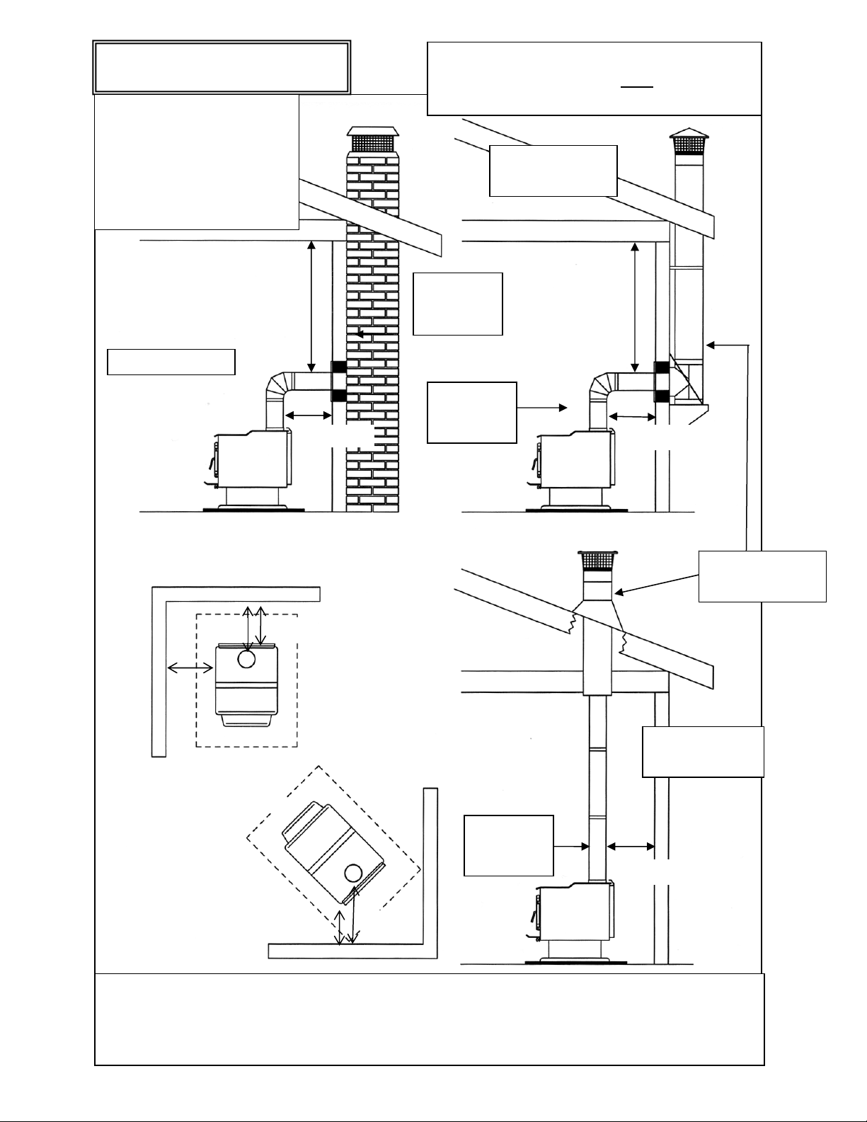
INSTALLATION APPLICATIONS
Illustration 1
16.0” Min.
16.0” Min.
16” Min.
18.0” Min.
18.0” Min.
NOTE:
1.
Horizontal run not to exceed 6’.
2. Total flue length should not
exceed 25’.
3. Floor protection required:
Min. size 39” x 52.5”.
4. Always check local codes for
clearances, installation, etc.
See Note
(
3
)
See Note
(
3
)
See Note (3)
See Note (3)
And Floor Protection section
B
D
Masonr
y
Chimne
y
(Exterior) Wall
Supported
(Interior) Ceiling
Supported
Single Wall
Chimney
Connector
Lined with
clay tile or
other liner
C
E
A
*IMPROPER INSTALLATION: The manufacturer will not be held responsible for damage caused by
the malfunction of a stove due to improper installation. Do not use makeshift methods or material
which may compromise the installation. England’s will not be liable for consequential or indirect
damages to property or persons resulting from the use of this product.
Call
(
800-245-6489
)
and/or consult a
p
rofessional installer if
y
ou have an
y
q
uestions.
Single Wall
Chimney
Connector
Class “A”
Chimney System
Followallventingsystemmanufacturer’s
installationrequirementsANDtheir
requiredclearances.
7
INSTALLATION APPLICATIONS, Cont’d.
Illustration 1b
8
8”
Pre-Manufactured Flue System: In the past few years pre-manufactured flue systems have
become very popular, because this type system is easily installed and, when done correctly, is very
safe. There are many pre-manufactured flue systems on the market, and when making your choice it
should be U.L., B.O.C.A. or I.C.B.O. approved. Any of these systems are constructed of the proper
materials and meet the proper safety standards. Your local dealer normally handles an approved
brand of flue pipe. There are two very popular methods for installation of this type system.
The first, most popular and least expensive is through the ceiling and out the roof. This is the
most direct route and creates a good draw because it requires less pipe. It is less expensive because
insulated pipe is needed only from the ceiling to the roof and above -- single wall 24 gauge or thicker
pipe is used from the unit to the ceiling if you maintain sixteen inches (16.0”) of clearance from all
combustible material.
The second method for installing a pre-manufactured system is to exit through the wall and run
the system vertically up the outside of the structure. This method is more expensive because more
insulated pipe is required -- you must use insulated pipe through the wall and up the outside of the
structure. In either installation, proper clearances to combustibles should be maintained. Your flue
pipe manufacturer furnishes a wall thimble or ceiling support box and, when installed properly, the
correct clearances are achieved. If you are unable to install this type system your local dealer may be
able to recommend a qualified contractor for this installation. It is the customer’s responsibility to
ensure that his system is installed properly and is in good operating condition.
The manufacturer will not be responsible for an accident caused by a unit connected to a faulty
flue system.
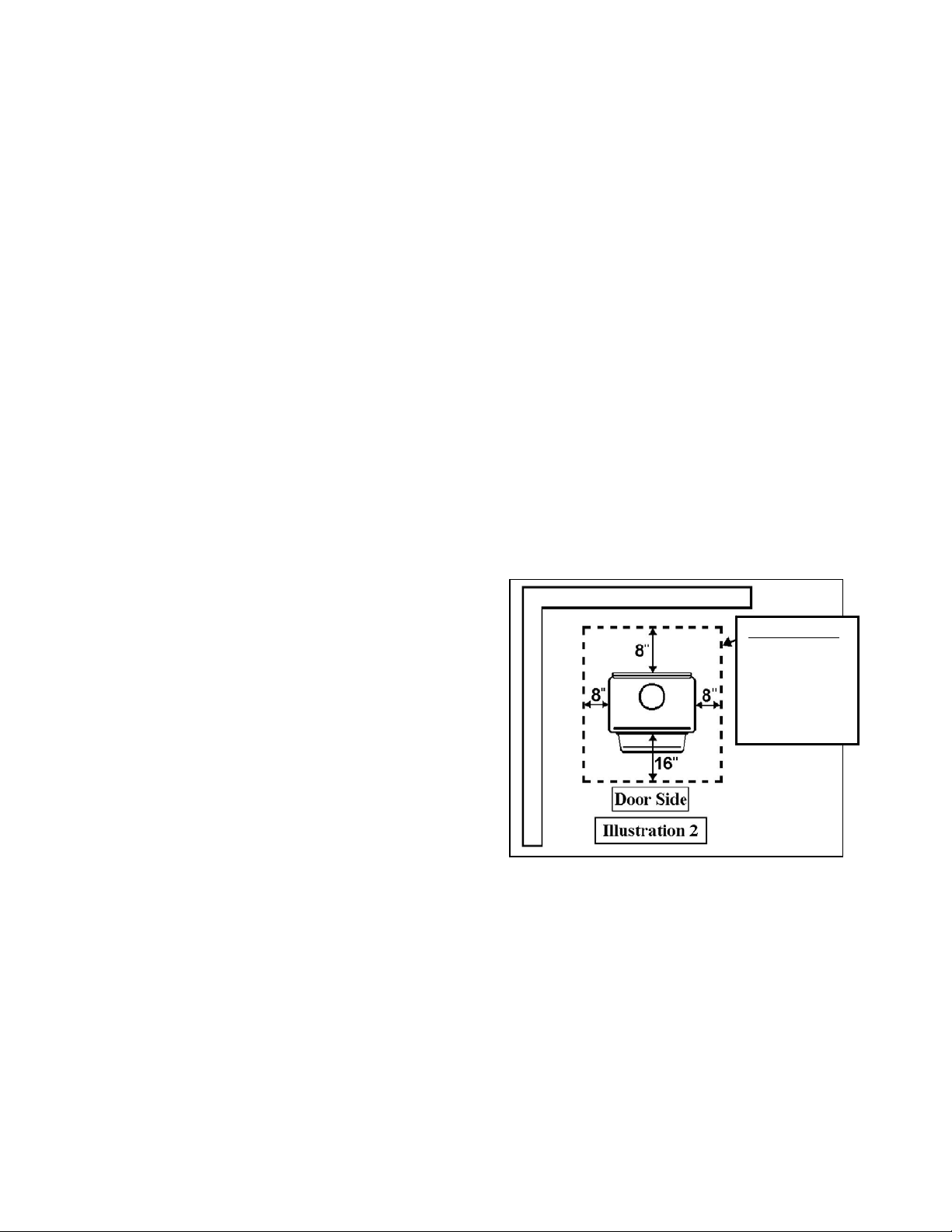
FLOOR AND WALL PROTECTION
1. Floor Protection
You will not need any floor protection if your
floor is constructed of a non-combustible material
such as brick or concrete. If your floor is
constructed with a combustible material such as
hardwood, carpet or linoleum, you must place
protection between the stove and the combustible
material.
There are many floor and wall board
manufacturers, and you should be very cautious
in choosing the proper protection. The type board
you choose should be U.L. rated and listed. After examining the area you plan to place your stove
and determining it requires a board, the next step is to select the proper size. The stove you
choose will determine the size board that is required. The approved protector board should be
large enough to provide a minimum of eight inches (8”) behind the unit, eight inches (8”) on both
sides and sixteen inches (16”) in the front where the door is located. The protection must have an
R-value of 1.5 (English units) or equivalent (See “Installation on a Combustible Floor”). This stove
requires a minimum 39.0” x 52.5” floor protection.
Installation on a Concrete Floor
An appliance mounted on a concrete floor does not require floor protection.
Carpeting and any other combustible material must not cover the Floor Protector.
If a combustible surface is applied to the concrete floor, a clearance must be maintained
equivalent to the area reserved for the floor protector.
Floor Protector
-Minimum R
value of 1.5
-Minimum size:
39”W
x 52.5”D
 Loading...