England's Stove Works 13-NCI, 50-SNC13I Owner's Manual

INSTALLATION & OPERATION MANUAL
MODEL NUMBERS: 13-NCI 50-SNC13I |
50-TNC13I |
Thank you for purchasing this product from a fine line of heating equipment. We wish you many years of safe heating pleasure with your new heating appliance.
Save These Instructions.
NOTE: IF YOU HAVE A PROBLEM WITH THIS UNIT DO NOT RETURN IT TO THE DEALER. CONTACT TECHNICAL SUPPORT @ 1-800-245-6489.
Questions? Need Parts or Options? www.englanderstoves.com
Please Note the Following Precautionary Statements:
England’s Stove Works highly recommends the use of smoke detectors and Carbon Monoxide detectors with any hearth product, including this unit. Follow all manufacturer’s instructions when using smoke or Carbon Monoxide detectors.
CAUTION: This unit must be installed in accordance with these instructions and must comply with local building and fire codes. Failure to do so could result in a chimney or house fire.
Keep children, furniture, fixtures, and all combustible materials away from any heating appliance. Refer to this owner’s manual for all clearances to combustible materials.
DO NOT INSTALL THIS UNIT IN A MOBILE HOME OR DOUBLE WIDE!!!
DO NOT INSTALL THIS UNIT IN A PRE-MANUFACTURED FIREPLACE!!!
FOR MASONRY FIREPLACE INSTALLATION ONLY!!!
SAVE THIS MANUAL FOR FUTURE REFERENCE
Read this entire manual before you install and use your new room heater. If this room heater is not properly installed, a house fire may result. To reduce the risk of fire, follow the installation instructions. Failure to follow instructions may result in property damage, bodily injury, or even death.
Rev. 9/2014
1

A letter from our Technical Support department:
Thank you for purchasing this fine product from England’s Stove Works!
England's Stove Works was started, and is still owned by, a family that believes strongly in a "Do It Yourself" spirit – that’s one reason you found this product at your favorite “Do It Yourself” store.
We intentionally design and build our stoves so that any homeowner can maintain his or her unit with basic tools, and we're always more than happy to show you how to do the job as easily and as inexpensively as possible.
From our free, downloadable service sheets, to our new "wizard-style," clickthrough Troubleshooting guide on our web site, we have always tried to help our customers stay "heat-ready," especially when oil and electricity prices continue to skyrocket.
Please look at our vast Help section on our web site and call our Technical support department at (800) 245-6489 if you need any help with your unit. We are nearly always able to help “walk you through” any repairs, problems or questions you may have.
PLEASE NOTE: While information obtained on our web site and through our 800 number is always free of charge, there will be a service charge incurred with any “on-site” repairs or maintenance that we may arrange.
Wishing you years of efficient, quality and “comfy” heating,
England’s Stove Works Technical Support Department
www.englanderstoves.com
(800) 245-6489
IF YOU HAVE A PROBLEM WITH THIS UNIT DO NOT RETURN IT TO THE DEALER.
CONTACT CUSTOMER SERVICE at 1 (800) 245-6489.
2
CAUTION
We highly recommend installation of this fireplace insert by a professional installer.
The “Direct Connect” method of installation must be used (see Installation section of manual).
If you have any doubt concerning your ability to complete your installation in a professional-like manner after reading these instructions, you should obtain the services of an installer who is versed in all aspects as to the correct and safe installation. Do not use temporary, makeshift compromises during installation. Do follow all applicable codes.
BEFORE INSTALLATION OF YOUR APPLIANCE
1.HOT WHILE IN OPERATION. KEEP CHILDREN, CLOTHING AND FURNITURE AWAY. CONTACT MAY CAUSE SKIN BURNS.
2.DO NOT BURN GARBAGE OR FLAMMABLE FLUIDS.
3.Check with the building inspector’s office for compliance with local codes; a permit may be required.
4.Always connect this unit to a chimney and NEVER vent to another room or inside a building.
5.DO NOT connect to any duct work to which another appliance is connected, such as a furnace.
6.DO NOT connect this unit to a chimney flue serving another appliance.
7.DO NOT USE CHEMICALS OR FLUIDS TO START THE FIRE.
8.The connector pipe and chimney should be inspected periodically and cleaned if necessary.
9.Remember the clearance distances when you place furniture or other objects within the area. DO NOT store wood, flammable liquids or other combustible materials too close to the unit.
10.Contact your local fire authority for information on how to handle a chimney fire. Have a clearly understood plan to handle a chimney fire. In the event of a chimney fire, turn air control to a closed position and CALL THE FIRE DEPARTMENT.
11.DO NOT tamper with the combustion air control beyond normal adjustment.
12.Once the required draw is obtained, operate only with doors closed; open doors slowly when re-fueling (this will reduce or eliminate smoke from entering the room).
13.DO NOT install these units in a mobile home or trailer. These units are NOT mobile home approved.
14.Visit our web site at www.englanderstoves.com for helpful information, frequently asked questions, parts/accessory orders and more. Technical support: (800) 245-6489.
3
SAFETY NOTICE:
IF THIS STOVE IS NOT PROPERLY INSTALLED, A HOUSE FIRE MAY RESULT. FOR YOUR SAFETY, FOLLOW THE INSTALLATION DIRECTIONS. CONTACT LOCAL BUILDING OR FIRE OFFICIALS FOR RESTRICTIONS AND INSPECTIONS IN YOUR AREA.
SECTION I: FLUE SYSTEM
This stove is designed to install into a masonry fireplace. The minimum opening is 28” wide x
24” high x 16” deep and you must have at least fourteen inches (14”) of hearth extending from the fireplace face.
Flue Size Needed:
The proper flue size is normally determined by the inside diameter of the opening on the unit, which in this case is six inches (6”). Therefore, the connector pipe should be the same size or larger and never less in diameter than the opening on the stove. The area of the chimney liner in square inches must also be equal to or larger than the area of the opening on the stove. If the area of the flue is larger than the area of the opening on the stove, it should never be more than three (3) times larger.
SECTION II: INSTALLATION INTO A MASONRY FIREPLACE
A. Preparation
1.Measure your hearth to ensure it is large enough to accept the unit. Your hearth should be at least thirty-six inches (36”) wide and fourteen inches (14”) from the face of the fireplace to the edge of the hearth.
2.Inspect your hearth to be sure it is constructed of a noncombustible material such as brick or stone. Do not install this stove on a hearth that is constructed of wood framework that is covered by brick or stone and do not install this unit in a zero (0) clearance fireplace. The manufacturer will not be held responsible for an accident resulting from this stove being installed on a hearth constructed of a combustible material.
3.Inspect your fireplace to ensure it is in proper working order and free of any obstructions.
4.Prior to installation, remove the existing damper or wire it to fasten it open.
5.Place the insert on the hearth and slide about one-third (1/3) of it into the opening.
B.Venting Your Insert Direct Connect
When this unit is direct connected it will require six inch (6”) diameter 24 gauge pipe from the stove through the damper opening. (NOTE: The chimney connector must be attached to the appliance with a minimum of three (3) screws, and 3 screws should be used to attach each adjoining section.) This will make it necessary to block off the open area on both sides of the pipe that passes through the damper opening, which can be done with sheet metal or by packing flame retardant fiberglass insulation in the open areas (no paper or combustibles). You must be sure the draft from the chimney is being pulled through the stove, and not around the connector pipe. (See Illustration 3 and “Backplate Instructions”). We highly recommend you have this done by a professional. You should contact your local authorities to be sure you are following all codes.
4

*IMPROPER INSTALLATION: The manufacturer will not be held responsible for damage caused by the malfunction of a stove due to improper installation. Do not use makeshift methods or material which may compromise the installation. England’s will not be liable for consequential or indirect damages to property or persons resulting from the use of this product.
Call (800-245-6489) and/or consult a professional installer if you have any questions.
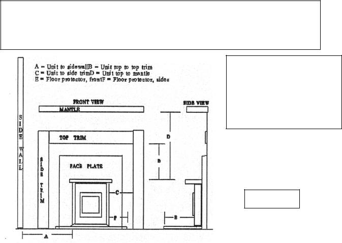
CLEARANCES:
A = 13 inches (330 mm)
B = 16 inches (407 mm)
C = 11 inches (280 mm)
D = 20 inches (508 mm)
E = 16 inches (407 mm)
F = 8 inches (204 mm)
Illustration 1
SECTION III: IMPORTANT OPERATION INSTRUCTIONS
“Draft” is the force that moves air from the appliance up through the chimney. The amount of draft in your chimney depends on the length of the chimney, local geography, nearby obstructions, and other factors. Too much draft may cause excessive temperatures in the appliance. An uncontrolled burn or a glowing red part or chimney connector can indicate excessive draft. Inadequate draft may cause back puffing into the room and “plugging” of the chimney and/or cause the appliance to leak smoke into the room through appliance and connections.
Today’s solid fuel appliances are much more efficient than in the past. The units are designed to give you controlled combustion, as well as maximum heat transfer, using less fuel to do so.
The design of your new appliance is such that the exhaust “smoke” is now at lower temperatures than in the past, therefore requiring proper chimney size to give adequate draft. If your chimney is too large, the heating appliance will have a difficult time to raise the “chimney flue” temperature to give adequate draft, therefore causing a smoke back up, poor burn, or both.
Should you experience such problems, call in a local chimney expert.
With the door closed, the rate of burning is regulated by the amount of air allowed to enter the unit through the air control. With experience, you will be able to set the control for heat and burning time desired.
5

Attempts to achieve higher output rates that exceed heater design specifications can result in permanent damage to the heater. The recommended wood load is level with the top of the firebricks. Overloading may prevent sufficient air entering the heater to properly fuel the fire.
Do not tamper with the combustion air control beyond the normal adjustment capacity.
Operate this heater only with the door closed.
ALWAYS PROVIDE A SOURCE OF FRESH AIR INTO THE ROOM WHERE THE UNIT IS INSTALLED. FAILURE TO DO SO MAY RESULT IN AIR STARVATION OF OTHER FUEL BURNING APPLIANCES AND THE POSSIBLE DEVELOPMENT OF HAZARDOUS CONDITIONS.
THIS HEATER IS EXTREMELY HOT WHILE IN OPERATION. SERIOUS BURNS CAN RESULT FROM CONTACT. CAUTION SHOULD BE OBSERVED, ESPECIALLY WHEN CHILDREN ARE PRESENT.
BLOWER ASSEMBLY: MODEL AC-13BA
115 VOLTS, 60 Hz, 0.83 AMPS, 3060 RPM
DANGER: RISK OF ELECTRIC SHOCK. DISCONNECT POWER BEFORE SERVICING.
BLOWER MOTOR OPERATING INSTRUCTIONS:
This unit is set up with a variable speed blower motor. The fan speed should be run on “Low” when the unit is operating at lower burn settings, and set to “High” for high burns. The blower will move air under, around and exit over the top of the front of the stove.
BLOWER INSTALLATION:
To install the blower, simply place it under the ash lip in the front of the stove. The blower should be removed and cleaned at least once per year; you can use a vacuum cleaner to remove any loose dust build-up, but DO NOT disassemble the blower. The blower should not require any oil.
When routing power cord, be sure that the cord does not come into contact with any hot surface.
SECTION IV: Optional Brass Trim
The AC-105 trim kit covers the two front edges of the stove and the three edges of the cover plate. The stove lip trim simply snaps over the edges of the stove. There are two angle clips that hold the three pieces of cover plate trim together – connect the three edges together and slide from the top down over the cover plate edges. The top piece of trim must be forced out slightly so it will connect with the top edge of the plate.
6
SECTION V: FLOOR PROTECTION
Hearth Extension
The firebox on your insert will extend out eight inches (8”) from the face of the fireplace, so you will need at least sixteen inches (16”) in front of the door. If you do not have this, it will require you to place an approved floor protector in front of the stove (such as a hearth extender shield).
Alternate Floor Protection:
An easy means of determining if a proposed alternate floor protector meets requirements is to follow this procedure:
1)Convert specification to R-value:
iR-value is given – no conversion is needed
iik-factor is given with a required thickness (T) in inches: R = 1/k x T
iiiC-factor is given: R = 1/C
2)Determine the R-value of the proposed alternate floor protector:
iUse the correct formula given in step 1 (above) to convert values not expressed as “R.”
iiFor multiple layers, add R-values of each layer to determine overall R-value.
3)If the overall R-value of the system is greater than the R-value of the specified floor protector, the alternate is acceptable.
EXAMPLE:
The specified floor protector should be ¾” thick material with a k-factor of 0.84. The proposed alternate is 4” brick with a C-factor of 1.25 over 1/8” mineral board with a k-factor of 0.29.
Step (a): Use formula above to convert specification to R-value.
R = 1/k x T = 1/0.84 x .75 = 0.893
Step (b): |
Calculate R of proposed system. |
|
|
|
|
|||
|
4” brick of C = 1.25, therefore R brick = 1/C =1/1.25 = 0.80 |
|
|
|||||
|
1/8” mineral board of k = 0.29, therefore Rmin.bd. = 1/0.29 x 0.125 = 0.431 |
|||||||
|
Total R = Rbrick + Rmineral board = 0.8 + 0.431 = 1.231 |
|
|
|||||
Step (c): |
Compare proposed system of R of 1.231 to specified R of 0.893. |
|
|
|||||
|
Since proposed system R is greater than required, the system is acceptable. |
|||||||
Definitions: |
|
|
|
|
|
|
|
|
|
Thermal conductance = C |
= |
Btu |
= |
W |
|
|
|
|
|
|
|
(hr)(ft2)(deg F) |
|
(m2)(deg K) |
|
|
|
Thermal conductivity |
= k |
= |
(Btu)(inch) |
= |
W |
= |
Btu |
|
|
|
|
(hr)(ft2)(deg F) |
|
(m)(deg K) |
|
(hr)(ft)(deg F) |
|
Thermal resistance |
= R |
= (ft2)(hr)(deg F) |
= |
(m2)(deg K) |
|
|
|
|
|
|
|
Btu |
|
W |
|
|
7
 Loading...