


PELLET AUXILIARY HEATER
INSTALLATION & OPERATION MANUAL
25 PAH/55 SHPAH/55 TRPAH
Manufactured By:
England’s Stove Works, Inc.
PO Box 206
Monroe, VA 24574
REV. 9/5/2012
CAUTION
Please read this entire manual before installation and use of this pellet fuel burning appliance. Keep children, furniture, fixtures and all combustibles away from any heating appliance.
SAFETY NOTICE
Failure to follow these instructions can result in property damage, bodily injury or even death. For your safety and protection, follow the installation instructions outlined in this manual. Contact your local building or fire officials about restrictions and installation inspection requirements (including permits) in your area.
SAVE THESE INSTRUCTIONS

IMPORTANT: IF YOU HAVE A PROBLEM WITH THIS UNIT, DO NOT RETURN IT TO THE DEALER. CONTACT TECHNICAL SUPPORT @ 1 800 245 6489
Mobile Home Use:
This freestanding pellet unit is approved for mobile home or doublewide installation with the outside combustion air hook up. See the “Installation” section of this manual for details pertaining to mobile home installations. Mobile home installation must be in accordance with the Manufactured Home and Safety Standard (HUD), CFR 3280, Part 24.
WARNING:
Use of outside combustion air is mandatory with this unit.
Do not operate with the hopper open; lid must be shut and tightly latched during operation.
Note: England’s Stove Works does not recommend using a pellet stove as your only source of heat.
Retain for your files
Model Number________________________
Date of Purchase_______________________
Date of Manufacture____________________
Serial Number_________________________
* This information can be found on the safety tag attached to the underside of the hopper lid. Have this information on hand if you phone the factory or your dealer regarding this product.
2
IMPORTANT! READ AND FOLLOW ALL INSTALLATION AND MAINTENANCE INSTRUCTIONS, INCLUDING CLEANING THE UNIT AS SPECIFIED, AND REPLACING GASKETS ANNUALLY, AND PARTS AS NEEDED.
ENGLAND’S STOVE WORKS IS NOT RESPONSIBLE FOR ANY DAMAGE OR INJURY INCURRED DUE TO NEGLECT, OR DUE TO UNSAFE INSTALLATION OR USAGE OF THIS PRODUCT. CALL TECHNICAL SUPPORT WITH QUESTIONS.

TABLE OF CONTENTS
Introduction |
|
|
|
Introduction ................................. |
4 |
Specifications |
|
|
|
Heating Specifications.................. |
5 |
|
Dimensions................................... |
5 |
|
EPA Compliance ........................... |
5 |
Installation |
|
|
|
Installation Overview ................... |
6 |
|
Clearances to Combustibles......... |
7 |
|
Venting Introduction.................... |
8 |
|
Venting Guidelines....................... |
8 |
|
Additional Venting Information... |
9 |
|
Vent Termination Clearances .... |
10 |
Approved Venting Methods
|
o |
Through the Wall ........... |
11 |
|
o |
Through the Ceiling........ |
12 |
|
o |
Existing Chimney............ |
13 |
|
Mobile Home Installation .......... |
14 |
|
|
Outside Air Hook Up .................. |
15 |
|
|
Floor Protection ......................... |
16 |
|
Daily Operation |
|
||
|
Getting Started........................... |
17 |
|
|
Lighting a Fire........................ |
17 18 |
|
|
Control Board Settings............... |
19 |
|
|
Error Codes ................................ |
20 |
|
|
Power Failure ............................. |
21 |
|
|
Thermostat Installation.............. |
22 |
|
|
Thermostat Operation ............... |
23 |
|
|
Optional Accessories.................. |
23 |
|
Maintenance
Daily |
|
|
o |
Important Notes............. |
24 |
o |
Daily Ash Removal..... |
24 25 |
o |
Cleaning the Burnpot |
..... 25 |
Monthly |
|
|
o |
Important Notes............. |
26 |
o |
Exhaust Chamber ...... |
26 27 |
o |
Venting Pipe................... |
27 |
Yearly
|
o |
Important Notes............. |
28 |
|
o |
Exhaust Blower .............. |
29 |
|
o |
Convection Blower......... |
30 |
|
o |
Hopper Fines .................. |
30 |
|
o |
Checking Gaskets ........... |
30 |
Troubleshooting Guide |
|
||
|
Troubleshooting.................... |
31 32 |
|
Replacing Components |
|
||
|
Auger Motor............................... |
33 |
|
|
Convection Blower..................... |
34 |
|
|
Combustion Blower ................... |
34 |
|
|
Vacuum Sensor .......................... |
35 |
|
|
Igniter......................................... |
|
35 |
|
Gaskets....................................... |
36 |
|
|
Finish .......................................... |
|
36 |
|
Glass ........................................... |
|
37 |
|
Control Board............................. 38 |
||
|
Wiring Diagram .......................... |
39 |
|
Illustrated Parts Detail and Tag |
|||
|
Exploded Parts Diagram............. |
40 |
|
|
Parts List..................................... |
41 |
|
|
Sample Safety Tag...................... |
42 |
|
Warranty |
|
|
|
|
Warranty Details ................... |
43 44 |
|
|
Warranty Reg. Form.............. |
45 46 |
|
3
IMPORTANT! READ AND FOLLOW ALL INSTALLATION AND MAINTENANCE INSTRUCTIONS, INCLUDING CLEANING THE UNIT AS SPECIFIED, AND REPLACING GASKETS ANNUALLY, AND PARTS AS NEEDED.
ENGLAND’S STOVE WORKS IS NOT RESPONSIBLE FOR ANY DAMAGE OR INJURY INCURRED DUE TO NEGLECT, OR DUE TO UNSAFE INSTALLATION OR USAGE OF THIS PRODUCT. CALL TECHNICAL SUPPORT WITH QUESTIONS.

INTRODUCTION
Thank you for purchasing this fine product from England’s Stove Works!
England’s Stove Works was started, and is still owned by, a family that believes strongly in a “Do It Yourself” spirit; that’s one reason you found this product at your favorite “Do It Yourself” store.
We intentionally design and build our stoves so that any homeowner can maintain their unit with basic tools, and we’re always more than happy to show you how to do the job as easily and as inexpensively as possible. However, while remaining simple, our stoves are designed to perform extremely efficiently, helping deliver more heat from less fuel.
Please look at our vast Help section on our website and call our Technical Support Department at (800) 245 6489 if you need any help with your unit. We are nearly always able to “walk you through” any installation issues, repairs, problems or other questions that you may have.
Wishing you years of efficient, quality and “comfy” heating,
EVERYONE AT ENGLAND’S STOVE WORKS
Please Note: While information obtained from our web site and through our Technical Support line is always free of charge, there will be a service charge incurred with any “on site” repairs or maintenance that we may arrange.
This manual encompasses all versions of the 25 PAH, including the 55 SHPAH, 55 SPAHL and 55 TRPAH. However, for simplicity of description, the stove will be referred to by the generic 25 PAH designation.
4
IMPORTANT! READ AND FOLLOW ALL INSTALLATION AND MAINTENANCE INSTRUCTIONS, INCLUDING CLEANING THE UNIT AS SPECIFIED, AND REPLACING GASKETS ANNUALLY, AND PARTS AS NEEDED.
ENGLAND’S STOVE WORKS IS NOT RESPONSIBLE FOR ANY DAMAGE OR INJURY INCURRED DUE TO NEGLECT, OR DUE TO UNSAFE INSTALLATION OR USAGE OF THIS PRODUCT. CALL TECHNICAL SUPPORT WITH QUESTIONS.
SPECIFICATIONS
Heating Specifications
|
Heat Output Range** ............................................ |
11,000 BTU/hr – 25,000 BTU/hr |
Approximate Pellet Burn Rate** ............................................... |
1.6 lb/hr – 4.0 lb/hr |
|
|
Maximum Burn Time** .............................................................................. |
72 hours |
Approximate Square Footage Heated*** ..................................... |
800 2000 sq. ft. |
|
|
Hopper Capacity..................................................................................... |
120 pounds |
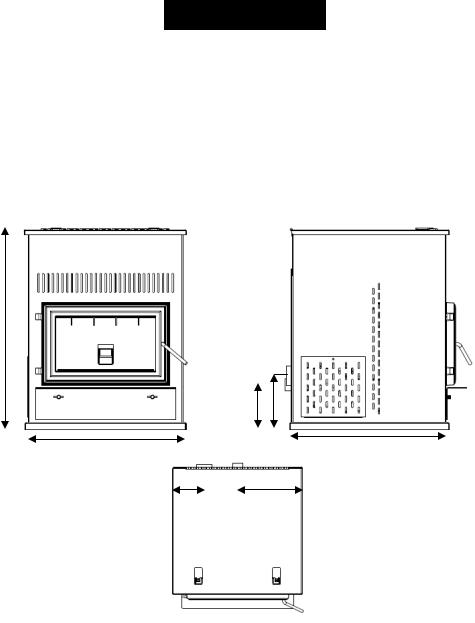
Dimensions
31.3125 in.
|
|
7.00 in. |
8.4375in. |
|
||
24.25 in. |
|
|
|
|
24.25 in. |
|
|
|
|
|
|||
|
|
12.125 in. |
||||
|
|
|
||||
5.5 in. |
|
|||||
EPA and Safety Compliance Specifications
|
EPA Compliance ........................................................................................... |
Certified |
|
Particulate Emissions .......................................................................... |
1.55 grams/hr |
|
Efficiency* ........................................................................................................... |
78% |
|
Tested To........................... |
ASTM E 1509, ULC/ORD C1482 M1990 & ULC S627 00 |
* This unit was not tested for efficiency; the efficiency shown is a default value normally attained by similar, certified pellet burning appliances.
**Heat output, burn rate and maximum burn time are heavily dependent on the type of pellets burned in the stove; as such, these numbers may vary.
***The maximum heating capacity of this unit can vary greatly based on climate, construction style, insulation and a myriad of other factors. Use this information in conjunction with a BTU loss calculation for your home to determine if this unit will be sufficient for your needs.
5
IMPORTANT! READ AND FOLLOW ALL INSTALLATION AND MAINTENANCE INSTRUCTIONS, INCLUDING CLEANING THE UNIT AS SPECIFIED, AND REPLACING GASKETS ANNUALLY, AND PARTS AS NEEDED.
ENGLAND’S STOVE WORKS IS NOT RESPONSIBLE FOR ANY DAMAGE OR INJURY INCURRED DUE TO NEGLECT, OR DUE TO UNSAFE INSTALLATION OR USAGE OF THIS PRODUCT. CALL TECHNICAL SUPPORT WITH QUESTIONS.

INSTALLATION
Installation Overview
When choosing a location for your new stove, there are a multitude of factors that should be taken into account before beginning the installation.
1.Traffic Patterns – To help prevent accidents, the stove should be placed in a location where it is out of the way of normal travel through the home.
2.Heat Flow – When deciding on a location for the stove, consider the way heat moves throughout your home. Install the stove where you need the heat; basement installations often do not allow sufficient heat to flow to the upper floors and a top floor installation will not allow any heat to reach the floors below. Always consider that heat rises and will take the path of least resistance while it is still hot.
3.Exhaust Location – Outside walls are generally the best place to install a stove, since they allow easy exhaust and intake air installation (using our DuraVent AC 3000 Kit, AC 33000 if Canada). If there is not a feasible way to install the stove on an outside wall, there are methods for venting the stove up through the roof, but they tend to be more costly because they involve the use of more pellet vent pipe and can often make outside air installation more difficult.
4.Wall Construction – Locating the stove so that the exhaust system can pass between studs will simplify the installation and eliminate the need to reframe any sections of the wall to accommodate the wall thimble.
WARNING
Do not store or use gasoline or other flammable vapors and liquids in the vicinity of this or any other appliance.
Do Not Overfire – If any external part starts to glow, you are overfiring. Reduce feed rate. Overfiring will void your warranty.
Comply with all minimum clearances to combustibles as specified. Failure to comply may result in a house fire.
Tested and approved for wood pellets only. Burning any other fuel will void your warranty.
6
IMPORTANT! READ AND FOLLOW ALL INSTALLATION AND MAINTENANCE INSTRUCTIONS, INCLUDING CLEANING THE UNIT AS SPECIFIED, AND REPLACING GASKETS ANNUALLY, AND PARTS AS NEEDED.
ENGLAND’S STOVE WORKS IS NOT RESPONSIBLE FOR ANY DAMAGE OR INJURY INCURRED DUE TO NEGLECT, OR DUE TO UNSAFE INSTALLATION OR USAGE OF THIS PRODUCT. CALL TECHNICAL SUPPORT WITH QUESTIONS.
INSTALLATION
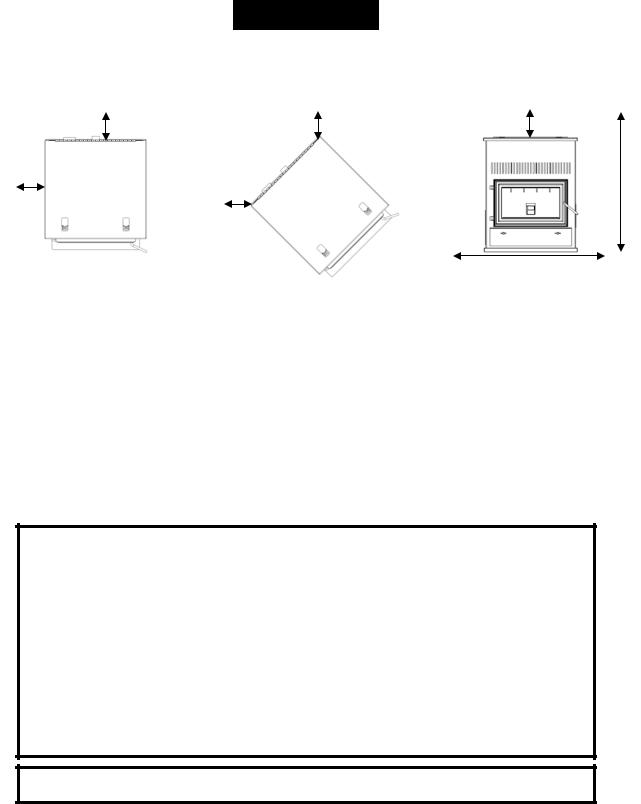
Clearances to Combustibles
|
|
|
|
|
|
|
|
|
|
|
B |
|
C |
|
|
D |
|
|
|
|
A |
|
|
|
|
|
|
E |
|
|
|
|
|
|
|
|
|
||
|
|
|
|
C |
|
|
|
|
|
|
|
|
|
|
|
|
F |
|
|
|
|
|
|
|
|
|
|
|
|
|
|
|
|
|
|
|
|
|
|
Unit to Side |
Unit to Rear |
Unit to |
Unit Top to |
Min. Ceiling |
Min. Alcove |
Max. Alcove |
Wall |
Wall |
Corner |
Ceiling |
Height |
Width |
Depth |
|
|
|
|
|
|
|
A |
B |
C |
D |
E |
F |
Not shown |
|
|
|
|
|
|
|
12 in. |
6 in. |
6 in. |
28.5 in. |
60 in. |
48.25 in. |
24 in. |
|
|
|
|
|
|
|
304.8 mm. |
152.4 mm. |
152.4 mm. |
723.9 mm. |
1524 mm. |
1225.6 mm. |
609.6 mm. |
|
|
|
|
|
|
|
CAUTION
Keep children away.
Supervise children in the same room as this appliance.
Alert children and adults to the hazards of high temperatures.
Do NOT operate with protective barriers open or removed.
Keep clothing, furniture, draperies and other combustibles away.
Installation MUST comply with local, regional, state and national codes and regulations.
Consult local building, fire officials or authorities having jurisdiction about restrictions, installation inspection, and permits.
DO NOT CONNECT TO ANY AIR DISTRIBUTION DUCT OR SYSTEM
7
IMPORTANT! READ AND FOLLOW ALL INSTALLATION AND MAINTENANCE INSTRUCTIONS, INCLUDING CLEANING THE UNIT AS SPECIFIED, AND REPLACING GASKETS ANNUALLY, AND PARTS AS NEEDED.
ENGLAND’S STOVE WORKS IS NOT RESPONSIBLE FOR ANY DAMAGE OR INJURY INCURRED DUE TO NEGLECT, OR DUE TO UNSAFE INSTALLATION OR USAGE OF THIS PRODUCT. CALL TECHNICAL SUPPORT WITH QUESTIONS.

INSTALLATION
Venting Introduction
This pellet stove operates on a negative draft system, which pulls combustion air through the burn pot and pushes the exhaust air through the vent pipe and out of the building. This unit must be installed in accordance with the following detailed descriptions of venting techniques; not installing the stove in accordance with the details listed here can result in poor stove performance, property damage, bodily injury or death. England’s Stove Works is not responsible for any damage incurred due to a poor or unsafe installation.
If questions arise pertaining to the safe installation of the stove, our Technical Support line (800 245 6489) is available. Contact your local code official to be certain your installation meets local and national fire codes and if you’re uncertain about how to safely install the stove, we strongly recommend contacting a local NFI certified installer to perform the installation.
Venting Guidelines
ALWAYS install vent pipe in strict adherence with the instructions and clearances included with your venting system.
DO NOT connect this pellet stove to a chimney flue which also serves another appliance.
DO NOT install a flue pipe damper or any other restrictive device in the exhaust venting system of this unit.
USE an approved wall thimble when passing through a wall and a ceiling support/fire stop when passing through a ceiling.
ONLY use 3.0” or 4.0” Type L or Type PL pipe approved for pellet stove venting; DO NOT use galvanized or B Vent pipe.
SEAL each joint of pellet vent with high temperature silicone (Part # AC RTV3) to prevent smoke spillage into the home.
AVOID excessive horizontal runs and elbows, as both will reduce the draft of the venting system and will result in poor stove performance.
INCLUDE as much vertical pipe as possible to prevent smoke from the unit from entering your home in the event of a power outage.
INSPECT your venting system often, to be certain it is clear of fly ash and other restrictions.
CLEAN the venting system as detailed in the maintenance section of this manual.
WARNING
INSTALL VENT AT CLEARANCES SPECIFIED BY THE VENT MANUFACTURER.
HOT! Do not touch! Severe burns or clothing ignition may result.
Glass and other surfaces are hot during operation.
WARNING: Venting system surfaces get HOT, and can cause burns if touched. Noncombustible shielding or guards may be required.
8
IMPORTANT! READ AND FOLLOW ALL INSTALLATION AND MAINTENANCE INSTRUCTIONS, INCLUDING CLEANING THE UNIT AS SPECIFIED, AND REPLACING GASKETS ANNUALLY, AND PARTS AS NEEDED.
ENGLAND’S STOVE WORKS IS NOT RESPONSIBLE FOR ANY DAMAGE OR INJURY INCURRED DUE TO NEGLECT, OR DUE TO UNSAFE INSTALLATION OR USAGE OF THIS PRODUCT. CALL TECHNICAL SUPPORT WITH QUESTIONS.

INSTALLATION
Additional Venting Information
Do not mix and match components from different pipe manufacturers when assembling your venting system (i.e. Do NOT use venting pipe from one manufacturer and a thimble from another).
We require a minimum vertical rise of 36 in. (3 ft.) of pipe to create natural draft in the system, which helps evacuate smoke from the stove in the event of a power failure or combustion blower failure.
Venting systems 15.0 ft. or shorter may be composed entirely of 3.0 in. pellet pipe; to reduce frictional losses, venting systems longer than 15.0 ft. should be composed of 4.0 in. pellet pipe.
Do not terminate the venting system directly beneath any combustible structure such as a porch or deck.
Follow NFPA 211 rules listed below for venting system termination location relative to windows and other openings in the dwelling (see also Vent Termination Clearances).
o NFPA 211 (2006 ed.) Section 10.4 Termination: 10.4.5
(1)The exit terminal of a mechanical draft system other than direct vent appliances (sealed combustion system appliances) shall be located in accordance with the following:
(a) Not less than 3 ft. (.91 m) above any forced air inlet located within 10 ft. (3.0m).
(b) Not less than 4 ft. (1.2 m) below, 4 ft. (1.2 m) horizontally from or 1 ft. (305 mm) above any door, window or gravity air inlet into any building.
(c) Not less than 2 ft. (0.61 m) from an adjacent building and not less than 7 ft. (2.1 m) above grade when located adjacent to public walkways.
Distance between the termination opening and grade should be a minimum of 24 in. contingent on the grade surface below the termination. When determining the termination height above grade, consider snow drift lines and combustibles such as grass or leaf accumulation. In areas where significant snowfall is possible, the termination height must be sufficiently high to keep the termination free of snow accumulation.
Do not use makeshift compromises during installation or install any component of the unit or venting system which could result in a hazardous installation.
A chimney connector shall not pass through an attic or roof space, closet or similar concealed space, or a floor, or ceiling.
Where passage through a wall, or partition of combustible material is desired, the installation shall conform to CAN/CSA B365.
9
IMPORTANT! READ AND FOLLOW ALL INSTALLATION AND MAINTENANCE INSTRUCTIONS, INCLUDING CLEANING THE UNIT AS SPECIFIED, AND REPLACING GASKETS ANNUALLY, AND PARTS AS NEEDED.
ENGLAND’S STOVE WORKS IS NOT RESPONSIBLE FOR ANY DAMAGE OR INJURY INCURRED DUE TO NEGLECT, OR DUE TO UNSAFE INSTALLATION OR USAGE OF THIS PRODUCT. CALL TECHNICAL SUPPORT WITH QUESTIONS.
VENT TERMINATION CLEARANCES
A)MIN. 4-FT CLEARANCE BELOW OR BESIDE ANY DOOR OR WINDOW THAT OPENS.
B)MIN. 1-FT CLEARANCE ABOVE ANY DOOR OR WINDOW THAT OPENS.
C)MIN. 2-FT CLEARANCE FROM ANY ADJACENT BUILDING.
D)MIN. 7-FT CLEARANCE FROM ANY GRADE WHEN ADJACENT TO PUBLIC WALKWAYS.
E)MIN. 2-FT CLEARANCE ABOVE ANY GRASS, PLANTS, OR OTHER COMBUSTIBLE MATERIALS.
F)MIN. 3-FT CLEARANCE FROM A FORCED AIR INTAKE OF ANY APPLIANCE.
G)MIN. 2-FT CLEARANCE BELOW EAVES OR OVERHANG.
H)MIN. 1-FT CLEARANCE HORIZONTALLY FROM COMBUSTIBLE WALL.
I)MUST BE A MINIMUM OF 36-INCHES ABOVE THE ROOF AND 24-INCHES ABOVE THE HIGHEST POINT OF THE ROOF WITHIN 10-FEET.
Notes on termination of Pellet Vent Pipe from NFPA 211 (2006 ed.) Section 10.4 Termination: 10.4.5 (See also “INSTALLATION” section of manual AND additional notes above):
1.Not less than three (3) feet above any forced air inlet located within ten (10) feet.
2.Not less than four (4) feet below, four (4) feet horizontally from, or one (1) foot above any door, window or gravity air inlet into any building.
3.Not less than two (2) feet from an adjacent building, and not less than seven (7) feet above grade where located adjacent to public walkways.
The exhaust exit shall be arranged so that the flue gases are not directed so that it will affect people, overheat combustible structures, or enter buildings. Forced draft systems and all parts of induced draft systems under positive pressure during operation shall be installed gastight or to prevent leakage of combustion products into a building. Through-the-wall vents shall not terminate over public walkways, or where condensate or vapor could create hazards or a nuisance.
Be sure to follow local codes and all manufacturer’s instructions (including exhaust pipe). Consult a professional installer and/or call Technical Support if you have any questions.
10
IMPORTANT! READ AND FOLLOW ALL INSTALLATION AND MAINTENANCE INSTRUCTIONS, INCLUDING CLEANING THE UNIT AS SPECIFIED, AND REPLACING GASKETS ANNUALLY, AND PARTS AS NEEDED.
ENGLAND’S STOVE WORKS IS NOT RESPONSIBLE FOR ANY DAMAGE OR INJURY INCURRED DUE TO NEGLECT, OR DUE TO UNSAFE INSTALLATION OR USAGE OF THIS PRODUCT. CALL TECHNICAL SUPPORT WITH QUESTIONS.
INSTALLATION |
|
For high altitude installations (above 4,000 |
|
|
ft.), the vent pipe should be increased from |
|
|
|
|
|
3-inch (3”) to four-inch (4”). |
Approved Venting Method 1: Through the Wall
Generally the simplest installation method, venting through the wall using our AC 3000 kit, AC 33000 if Canada (or similar venting system) is also the preferred venting method. It minimizes horizontal pipe, allows the stove to be installed close to the wall and keeps the clean out tee on the outside of the house, for ease of cleaning.
When installing any venting system, Type L or Type PL pipe must be used and all clearances to combustibles (listed by the pipe manufacturer) must be strictly adhered to.
Use the pipe manufacturer’s approved thimble for passing through a combustible wall, and maintain at least the minimum
clearances to combustibles.
Use an appliance collar where the pellet vent connects to the exhaust output of the pellet stove and attach the appliance collar to the exhaust blower output using three sheet metal screws.
Secure the pellet vent to the outside of the house using a wall strap just below the 90 degree elbow.
Seal each pipe connection joint with high temperature RTV Silicone, to ensure the system is leak free (Check with the specific venting system manufacturer’s instructions before doing so).
If the pellet vent pipe being used is not a “Twist Lock” system, three (3) sheet metal screws are required at each pipe joint.
Connect the pellet stove to outside combustion air using the kit included with your stove or using an alternative method, as described in the “Outside Air” section, on page 15.
This installation type can be modified for basement (Basement installations should always be performed by a professional installer) or other installations wherein the tee and vertical section of the pipe would be inside the home and the venting system would simply pass horizontally through the thimble and then terminate.
Please Note: Installation diagrams are for reference purposes only and are not drawn to scale, nor meant to be used as plans for each individual installation. Please follow all venting system requirements, maintain the required clearances to combustibles, and follow all local codes.
11
IMPORTANT! READ AND FOLLOW ALL INSTALLATION AND MAINTENANCE INSTRUCTIONS, INCLUDING CLEANING THE UNIT AS SPECIFIED, AND REPLACING GASKETS ANNUALLY, AND PARTS AS NEEDED.
ENGLAND’S STOVE WORKS IS NOT RESPONSIBLE FOR ANY DAMAGE OR INJURY INCURRED DUE TO NEGLECT, OR DUE TO UNSAFE INSTALLATION OR USAGE OF THIS PRODUCT. CALL TECHNICAL SUPPORT WITH QUESTIONS.

INSTALLATION
Approved Venting Method 2: Through the Ceiling
For high altitude installations (above 4,000 ft.), the vent pipe should be increased from 3-inch (3”) to four-inch (4”).
Venting through the ceiling/roof may be the only feasible venting option in some cases and is a factory recommended installation.
When installing any venting system, Type L or Type PL pipe must be used and all clearances to combustibles listed by the pipe manufacturer must be strictly adhered to.
Use the pipe manufacturer’s approved ceiling support for passing through a combustible ceiling, as well as the required firestops, radiation shields, flashing and storm collar.
Be certain to follow the manufacturer’s required height of termination above the roof line, and maintain at least the minimum clearances to combustibles.
Use an appliance collar where the pellet vent
connects to the exhaust output of the pellet stove and attach the appliance collar to the exhaust blower output using three sheet metal screws.
Seal each pipe connection joint with high temperature RTV Silicone, to ensure the system is leak free (Check with the specific pipe manufacturer’s instructions before doing so).
If the pellet vent pipe being used is not a “Twist Lock” system, three (3) sheet metal screws are required at each pipe joint.
Connect the pellet stove to outside combustion air using the kit included with your stove or using an alternative method, as described in the “Outside Air” section, on page 15.
This venting method can also be modified so that the venting system runs horizontally through the wall from the stove, then transitions to vertical and terminates above the roofline. When using this modified version of this installation be certain to carefully follow the venting system manufacturer’s instructions diligently.
Please Note: Installation diagrams are for reference purposes only and are not drawn to scale, nor meant to be used as plans for each individual installation. Please follow all venting system requirements, maintain the required clearances to combustibles, and follow all local codes.
12
IMPORTANT! READ AND FOLLOW ALL INSTALLATION AND MAINTENANCE INSTRUCTIONS, INCLUDING CLEANING THE UNIT AS SPECIFIED, AND REPLACING GASKETS ANNUALLY, AND PARTS AS NEEDED.
ENGLAND’S STOVE WORKS IS NOT RESPONSIBLE FOR ANY DAMAGE OR INJURY INCURRED DUE TO NEGLECT, OR DUE TO UNSAFE INSTALLATION OR USAGE OF THIS PRODUCT. CALL TECHNICAL SUPPORT WITH QUESTIONS.

INSTALLATION
For high altitude installations (above 4,000 ft.), the vent pipe should be increased from 3-inch (3”) to four-inch (4”).
Approved Venting Method 3: Existing Chimney System
Using an existing masonry or factory built chimney for venting is the only other acceptable method for venting this pellet unit.
Use Type L or Type PL venting pipe until entering the existing chimney. Use the appropriately sized adapter when transitioning from the pellet vent pipe to the masonry or factory built thimble and be certain that the adapter is sealed tightly to both the pellet venting system and the existing chimney.
Before using an existing chimney, be certain it is in good condition (A chimney sweep inspection is highly recommended). Also, make sure the chimney meets the minimum standards listed in NFPA 211 (A chimney professional can confirm this upon inspection).
If connecting this stove to a factory built chimney, it may ONLY be a 6” flue, UL103 HT venting system (ULC S629 if Canada). Connection to any other factory built chimney may result in a poorly operating or dangerous stove installation.
When connecting to an existing masonry chimney, the cross sectional area of the flue must be considered. A chimney with a flue larger than 6” round (28.27 sq. in.) may require relining with an approved pellet stove chimney lining system.
Use an appliance collar where the pellet vent connects to the exhaust output of the pellet stove and attach the appliance collar to the exhaust blower output using three sheet metal screws.
Seal each pipe connection joint with high temperature RTV Silicone, to ensure the system is leak free (Check with the specific pipe manufacturer’s instructions before doing so).
If the pellet vent pipe being used is not a “Twist Lock” system, three (3) sheet metal screws are required at each pipe joint.
Connect the pellet stove to outside combustion air using the kit included with your stove or using an alternative method, as described in the “Outside Air” section, on page 15.
Please Note: Installation diagrams are for reference purposes only and are not drawn to scale, nor meant to be used as plans for each individual installation. Please follow all venting system requirements, maintain the required clearances to combustibles, and follow all local codes.
13
IMPORTANT! READ AND FOLLOW ALL INSTALLATION AND MAINTENANCE INSTRUCTIONS, INCLUDING CLEANING THE UNIT AS SPECIFIED, AND REPLACING GASKETS ANNUALLY, AND PARTS AS NEEDED.
ENGLAND’S STOVE WORKS IS NOT RESPONSIBLE FOR ANY DAMAGE OR INJURY INCURRED DUE TO NEGLECT, OR DUE TO UNSAFE INSTALLATION OR USAGE OF THIS PRODUCT. CALL TECHNICAL SUPPORT WITH QUESTIONS.
|
|
For high altitude installations (above 4,000 |
INSTALLATION |
|
|
|
ft.), the vent pipe should be increased from |
|
|
|
3-inch (3”) to four-inch (4”). |
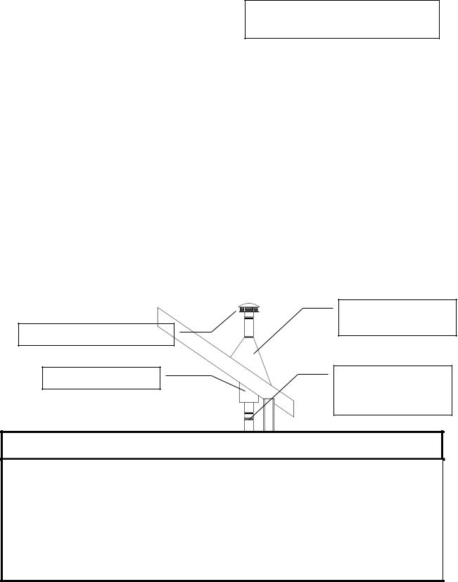
Mobile Home Installation
The England’s Stove Works, Inc. outside air kit MUST be used for installation of this unit in a mobile home. Please see the “Outside Air” section on page 15 for more information regarding outside air connections.
The outside air inlet must be kept clear of leaves, ice and other debris. Keeping the outside air inlet free of restriction is crucial to preventing air starvation and smoke spillage.
The pellet stove MUST be secured to the floor of the mobile home using lag bolts and the holes provided in the bottom of the base for this purpose. Outdoor aired space heaters must be attached to the structure.
The pellet stove MUST be grounded with #8 solid copper grounding wire (or equivalent), terminated at each end with an NEC approved grounded device.
Carefully follow all clearances listed in the appropriate section of this manual AND follow the venting manufacturer’s minimum clearance requirements. Similarly, be certain the venting system used is approved for mobile home use.
Installation must be in accordance with Manufacturers Home & Safety Standard (HUD) CFR 3280, Part 24 as well as any applicable local codes.
Use silicone to create an effective vapor barrier at the location where the chimney or outside air ducting passes through to the exterior of the structure.
|
|
|
Roof Flashing and |
|
|
|
|
Storm Collar |
|
Chimney Cap/Spark Arrestor |
||||
|
||||
|
|
Mobile Home |
||
|
|
|
||
|
Joist Shield/Firestop |
|
||
|
|
|
Approved Type P or PL |
|
|
|
|
||
|
|
|
Pellet Vent Pipe |
|
WARNING: DO NOT INSTALL IN A SLEEPING ROOM.
CAUTION
THE STRUCTURAL INTEGRITY OF THE MANUFACTURED HOME FLOOR, WALL
AND CEILING/ROOF MUST BE MAINTAINED.
DO NOT CUT THROUGH FLOOR JOISTS, WALL STUDS, CEILING TRUSSES OR ANY OTHER SUPPORTING MATERIAL WHICH COULD BE DETRIMENTAL TO THE STRUCTURAL INTEGRITY OF THE HOME.
14
IMPORTANT! READ AND FOLLOW ALL INSTALLATION AND MAINTENANCE INSTRUCTIONS, INCLUDING CLEANING THE UNIT AS SPECIFIED, AND REPLACING GASKETS ANNUALLY, AND PARTS AS NEEDED.
ENGLAND’S STOVE WORKS IS NOT RESPONSIBLE FOR ANY DAMAGE OR INJURY INCURRED DUE TO NEGLECT, OR DUE TO UNSAFE INSTALLATION OR USAGE OF THIS PRODUCT. CALL TECHNICAL SUPPORT WITH QUESTIONS.
 Loading...