

Page 1

MIDI INTERFACE
Z-7
Operator´s Manual
Please, first read this manual carefully!
Page 2

The MIDI INTERFACE enables you to execute MIDI switching operations and save switching
patches for amps/devices that are equipped with a MIDI INTERFACE PORT. It features
selective control via the 8 POLY channels or reception of all MIDI program changes from 01 to
100 via the OMNI mode.
Your ENGL device’s manual covers all MIDI-switchable functions in detail. This interface does not
require an external power supply; the amp/device provides the requisite current. Another
advantage of this device is that when it used in conjunction with the MIDI Footcontroller
Z- 12, the power for the footcontroller is routed from the MIDI Switcher via the MIDI cable. In
Practice this means the only cable you have to contend with is the MIDl cable to the footswitch!
The INTERFACE is easy to operate and handle, but nevertheless you should read this manual
carefully, especially the highlighted items. It contains a wealth of information you may need
later on if you have questions or encounter problems. Store it in a safe place for future
reference.
In order to simplify matters, from here on all references to an amp simply indicate any ENGL
product (combos, heads, 19" pre- and power amps) and interface denotes the ENGL MIDI
INTERFACE.
Components
1. ENGL MIDI INTERFACE
2. 1 Connector cable, 2 meters in length
(SUB-D plug on both ends, 1:1 connection ratio)
3. 4 adhesive rubber pads
4. 2 velcro strips
5. Operator’s Manual
FRONT
TATUS
WRITE / EDIT
1 WRITE/EDIT
This key executes the following functions:
A) WRITE: This feature saves every changed setting of programmable switching functions when the
interface is in the MIDI mode. Once you have changed one or several setting(s) at the amp(s), only
those settings you just updated are saved and their previous settings deleted when you press the key
for approx. 1 second. The delay ensures you do not unintentionally delete or overwrite a setting.
The STATUS LED (2) flashes briefly to indicate that the new setting is saved.
B) EDIT: This feature saves the current setting of every programmable switching function when the
interface is in the EDIT mode. The EDIT mode is ideal for initial programming or complete
re-programming. The EDIT mode is activated after you select a MIDI program location (MIDI mode),
provided you did not change a setting of programmable switching functions at the amp(s) before you
press this key for approx. 1 second. In this mode all settings at the amp(s) are identical to the
settings of the respective pushbuttons. The current setting of every programmable switching function
is saved once you press the key again. The EDIT mode is active when the STATUS LED (2) and the amp’s
MIDI MODE LED illuminates continuously.
2 STATUS
This red LED indicates different modes and functions:
a) The LED flashes slowly three times after you power the device up. This is the internal system self-test.
The LED estinguishes to indicate normal operating status after the system has been proved.
b) The LED flashes rapidly after you switch the device on to indicate a system error. A possible source of
the fault is a defective EEprom.
c) The LED flashes rapidly after you have selected a MIDI program location: The MIDI program change
has been transmitted via a MIDI channel which is not selected on the Interface. In other words the
MIDI channel being sent from the MIDI device (e.g. a MIDI Footcontroller) is not in accordance with
the MIDI channel on the Interface and therefore the Interface does not change to this program
location. As soon as a new MIDI program change command is received via the selected MIDI channel,
the LED stops flashing and the Interface changes to the respective program location.
d) The LED flashes briefly after you have pressed the WRITE/EDIT key: The Interface saves a single or
several changes in the MIDI mode or all settings in the EDIT mode.
S
1 2
MIDI CHANNEL PORT APORT B
3
4
MIDI INTERFACE
5
Page 3
e) The LED Illuminates continuously: The Interface is in Edit-mode.
f) The LED Illuminates continuously while you are pressing the WRITE/EDIT key: =>The Interface is in
the MANUAL mode; no Data can be saved. It stops to illuminate as soon as the key is released.
=>The MIDI program change has been transmitted via a MIDI channel which is not selected on the
Interface and therefore no Data can be saved. The LED blinks rapidly again once the key is released.
2 MIDI CHANNEL
These code switches enable you to set the MIDI channels to OMNI or POLY 1 through 8 for
MIDI data reception. The table below depicts the switch settings for the respective channels.
The same table is also located on the top panel of the Interface.
MIDI Data Switch settings code switches:
reception via 1 2 3 4
OMNI-Mode up x x x
POLY Channel 1 down up up up
POLY Channel 2 down up up down
up
1234
down
POLY Channel 3 down up down up
POLY Channel 4 down up down down
POLY Channel 5 down down up up
POLY Channel 6 down down up down
POLY Channel 7 down down down up
POLY Channel 8 down down down down
x => setting does not affect mode
4 PORT A
This green LED denotes that an amp is powered up and connected to INTERFACE PORT A.
This LED must be illuminated before the system can operate.
5 PORT B
This yellow LED denotes that an amp is powered up and connected to INTERFACE PORT B.
If just this LED is illuminated, then the interface is not operational because either INTERFACE PORT A
is not connected to an amp (a definite no go!) or the amp connected to Port A is not powered up.
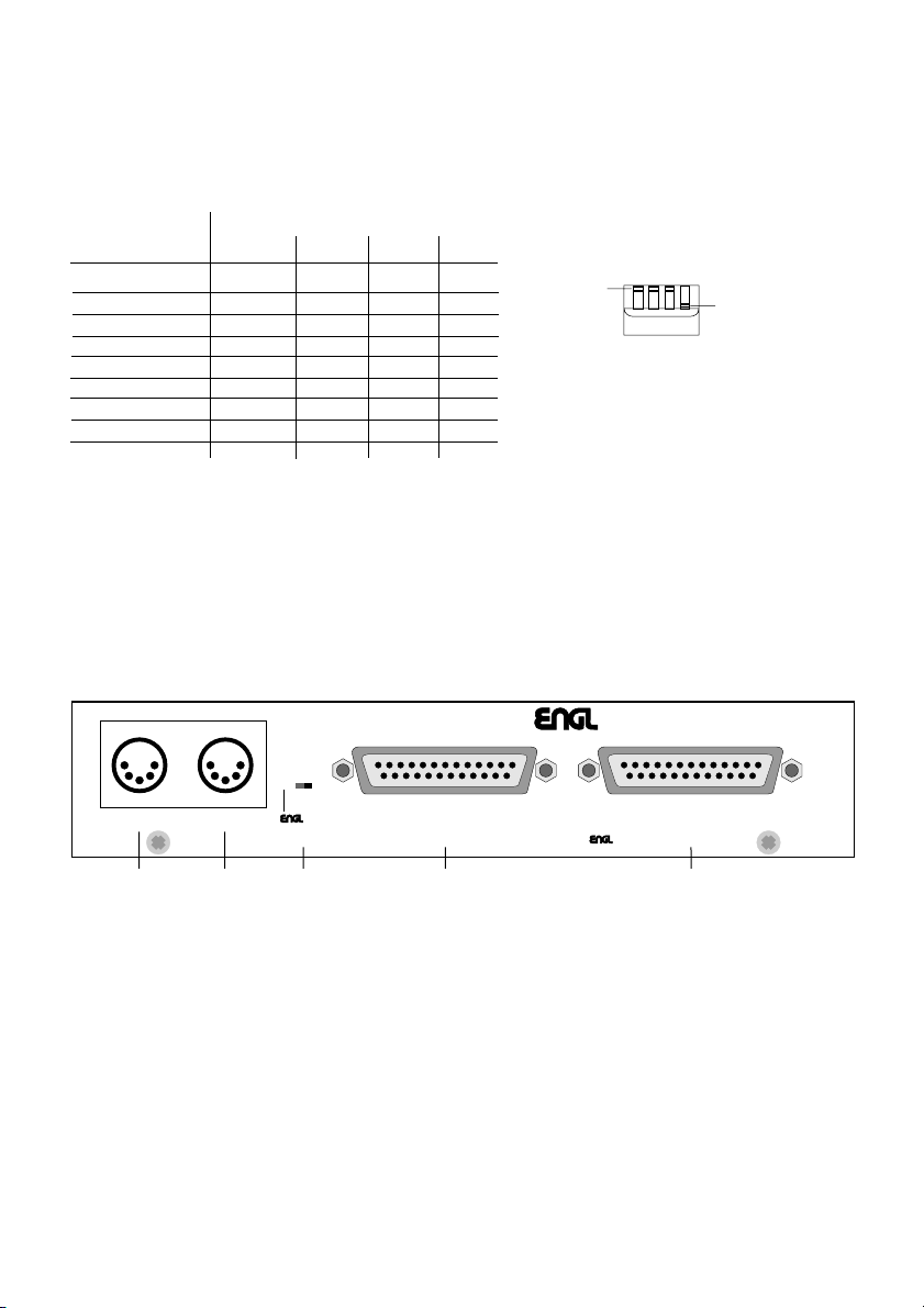
REAR PANEL
MIDI INTERFACE
x
MIDI THRU MIDI IN
6
6 MIDI THRU
Standard 5-pin diode jack. It sends incoming MIDI data from the MIDI IN jack to another connected
MIDI
FOOTCONTROLLER
Z-12
7 8 9 10
INTERFACE PORT BINTERFACE PORT A
CAUTION ! CONNECT TO OTHER DEVICE ONLY !
MIDI device.
7 MIDI IN
Standard 5-pin diode jack. It receives MIDI data from your MIDI footswitch.
This jack also supplies the current for the ENGL MIDI Footcontroller Z-12.
8 POWER SUPPLY SELECTOR SWITCH
This switch activates the power supply to the ENGL MIDI Footcontroller Z- 12 via the MIDI
cable. In position x (left), the power supply of the Interface is routed via Pin 1 and Pin 2 of the
MIDI IN port. If you use a MIDI footswitch of a another brand, set the switch to the right
position to prevent damage to the MIDI footswitch. If the footswitch is also equipped with a
phantom power circuit, refer to the footswitch user´s manual to determine which pins are
used to route the power supply as well as the voltage and current values. If the voltage and
power routing specifications are identical, you can set the switch to the left position to route
power to the MIDI footswitch via the MIDI cable.
PLEASE HEED THE FOLLOWING: A MIDI Footcontroller which is supplied with power
through the Interface, shall not consume more than 200 mA current. Keep in mind that the
voltage is approx.11 Volts AC at the respective Pins of the MIDI IN jack!
9 INTERFACE PORT B
25-pin SUB-D jack. Connect an additional ENGL amp equipped with a MIDI INTER FACE PORT here.
MADE IN GERMANYSER.NO.:
Page 4

10 INTERFACE PORT A
25-pin SUB-D jack. Connect an ENGL amp equipped with a MIDI INTERFACE PORT here.
This port also supplies power to the interface.
Setup and Installation:
There are a number of setup and installation options:
1. Place it on a flat surface: Attach the four adhesive rubber pads to bottom of the device.
2. Attach it to your ENGL device using the velcro strips ( e.g. to the SAVAGE 120’s rear panel ).
3. Mount it in a 19" rack system: This requires the optional rack-mount panel that you can attach to
the INTERFACE’s front panel via four screws.
Cable Connections:
1. Ensure all amps are switched off before installing the connector cable(s).
2. If you want to control a single amp via the interface, ensure you insert the cable’s plug in
INTERFACE PORT A (10); this port supplies the power. Connect the included cable and tightly fasten
the plugs’ mounting screws at both the interface and amp. If you want to control an additional amp,
connect it via an identical cable (optional) to INTERFACE PORT B (9).
3. Connect the ENGL MIDI controller Z-12 or other MIDI footswitch board to the MIDI IN (7) jack via
a special cable.You can use the MIDI THRU (6) jack to send MIDI information on to other devices
(FX processors, etc.).
4. NOTE: Ensure you never bend the connector cable at a radical angle near the INTERFACE PORTS
(at both the amp and interface) and avoid exposing these plugs/jacks to undue pressure or strain.
This applies to all MIDI cables as well.
NOTE: ESSENTIAL PRECAUTION!
Never connect INTERFACE PORTS A and B to a device that it is not designed for (e.g. computers,
printers, etc.), as this may dammage both the device and the interface.
Glossary
programmable switching functions: All switching functions at the amp that can be switched via MIDI
(e.g. channel switching, A/B switching, etc.) and their settings (e.g. Clean Crunch, Lead channels,
Master A or Master B settings etc.) can be saved in the interface. Consult your ENGL amp’s manual
for a detailed description of these functions.
Interface: In this case, an interface between MIDI data (serial) and ENGL amplifier data (special parallel
format). Data assignment in the interface is executed by saving the amp’s (or amps’) programmable
function settings in one of the 100 available memory locations.
MANUAL mode: This operating mode is active immediately after the amp connected to
INTERFACE PORT A is powered up, before you select a MIDI program location. The interface also
switches to this mode if a system reset is sent via the MIDI circuit. In this mode, you can control
programmable switching functions at the amp(s) in the normal manner, but you cannot save data.
Indication: STATUS-LED (2) is off, MIDI-MODE-LED on the amp(s) illuminates.
MIDI mode: This is the interface’s actual operating mode. It is active everytime you select a
MIDI program location. Here too, you can control programmable switching functions at the amp(s)
in the normal manner and save changed settings via the WRITE/EDIT key.
Indication: STATUS-LED (2) is off, MIDI-MODE-LED on the amp(s) is flashing rapidly if no setting has been
changed or it flashes slowly to indicate a setting of a programmable function has been changed.
EDIT mode: This is the interface mode in which you can program presets. Activate it by pressing the
WRITE/EDIT key in the MIDI mode before changing a setting of programmable switching functions
at the amp(s) (after selecting a MIDI program location). Exit the EDIT mode by pressing the WRITE/EDIT
key again to save all settings or select another MIDI program location to exit without saving the
settings. In this mode the STATUS LED (2) illuminates as well as the MIDI-MODE-LED(s) on the amp(s).
OMNI mode: The OMNI mode is selected via the interface’s DIP switches (MIDI CHANNEL). In this
receive mode, the interface reacts to all MIDI program change commands (01-100) regardless on which
(POLY) channel they are sent.
POLY channnel: This refers to a specific receive channel, i.e. one of the 16 channels available in accordance
with the MIDI standard. The interface can be set to POLY Channels 01 - 08. For instance if you set it to
POLY Channel 02, then it reacts to program change commands sent via POLY Channel 02 only and ignores
those sent on other channels. This option is useful if you have several MIDI-capable devices in a MIDI loop
and you want to address and switch devices individually. When a MIDI command is received at a channel
that is not selected on the Interface, the STATUS LED (2) flashes rapidly.
System reset: MIDI data command sent via the MIDI circuit; it switches the interface back to the
MANUAL mode.
Page 5

A) Changing and Saving the Setting of One or Several programmable Switching Functions,
through WRITE:
1. Select the desired MIDI program location (from 01 to 100).
=>The amp’s (or amps’) MIDI MODE LED(s) flash, the status of the programmable switching functions
reflect this program's presets. The interface is in the MIDI mode.
2. Change the setting(s) of (a) programmable switching function(s) at the amp(s)
(e.g. from the Clean to the Lead channel, from Master A to Master B, etc.).
Please note the following:
You may find you have to activate a pushbutton twice to achieve the desired status, depending on its
initial setting and the function’s status. The formula to follow is:
pushbutton setting is identical to the function status (LED indicator): activate once;
pushbutton setting is not identical to the function status (LED indicator): activate twice.
=>The setting(s) at the amp follows your operation, the MIDI-MODE-LED´s flash cycle becommes slowly
once a setting has been changed.
3. Press the WRITE/EDIT key (1) for approx. one second until the STATUS LED (2) flashes briefly.
=>Once the STATUS LED (2) has flashed, the program is updated and the changed setting(s) is (are) saved.
=>In the MIDI mode, you can change the setting of programmable switching functions at the amp(s) at
any time. If you do not want to save these changes, simply do not press the WRITE/EDIT key (1).
In this case, the next time you call this program location you will retrieve your original program.
B) Initial and Re-Programming through EDIT:
1. switch the amp that is connected to INTERFACE PORT A (10) on. If an additional amp is connected to
INTERFACE PORT B (9), then activate it as well.
=>The green PORT A LED (4) illuminates and indicates that the interface is operational. The yellow
PORT B LED (5) illuminates if an additional amp is powered up and connected to INTERFACE PORT B.
The red STATUS LED (2) at the Interface flashes slowly three times to indicate the system test.
The MIDI MODE LED illuminates continuously at the amp(s) and the interface is in the MANUAL mode.
2. Select the desired program location (from 01 to 100) via a controller (e.g. ENGL MIDI Footcontroller Z-12).
=>The amp’s (or amps’) MIDI MODE LED(s) flash and the status of the programmable switching functions
reflect this program’s presets. The interface is in the MIDI mode.
3. Press the WRITE/EDIT key (1) and release it as soon as the STATUS LED (2) illuminates.
=>The STATUS-LED (2) starts to illuminate after you held depressed the key for approx.1 second.
The MIDI MODE LED(s) at the amp(s) is (are) now continuously illuminated. The interface is switched
to the EDIT mode and the status of the programmable switching functions is identical to the current
settings of the respective pushbuttons at the amp(s).
4. Achieve the desired settings by operating the respective pushbuttons of programmable switching functions
at the amp(s) (e.g. Clean, Crunch or Lead channel, Master A or B, Presence A or B, Reverb on or off, etc.).
5. Press the WRITE/EDIT key (1).
=>Your selections are saved in the interface once the STATUS LED (2) flashes briefly and extinguishes.
The interface is now back in the MIDI mode and the MIDI MODE Led(s) at the amp(s) flash(es) again.
6. Follow the same sequence for programming other patches.
=>Once you exit the EDIT mode, the amp’s (or amps’) switching status is saved in the current configuration.
If you want to exit the EDIT mode without saving the current switching status, simply select the same or
any other MIDI program location. The MIDI MODE LED at the amp flashes again and the interface’s
STATUS LED (2) extinguishes to indicate that the interface is back in the MIDI mode.
IMPORTANT: Once you have programmed switching functions using two amps, ensure that the
next time you set up your system you use the same configuration to connect the amps to
INTERFACES PORTS A and B, otherwise you will be in for an unpleasant MIDI switching surprise!
To avoid a mistake, simply sign the cables and the ports at the amps with A and B.
TIPS: Use the EDIT mode to quickly and comfortably execute initial or re-programming. The current
switching status at the amp(s) is identical to the setting of the switches, thus providing an accurate visual
reference. Also, you can switch functions directly to achieve the switching status you want to program,
whereas in some cases in the MIDI mode you may be required to activate the pushbuttons twice.
Of course you can also re-program and save presets in the MIDI mode: Keep in mind that the actual setting
of switches may not be identical to the current switching status at the amp (MIDI control), which in some
configurations requires you to activate a pushbutton twice to achieve the desired setting. This programming
method is particularly convenient when you want to change one or just a few of a previously programmed
MIDI program location’s setting(s). In this case, we recommend that you do not resort to the EDIT mode,
as it saves all current switch settings (to include those at your additional amp, which may lead to inadverdent
deletion of the original settings). If you accidentally activated the EDIT mode, you can exit it at any time
without saving the new switching status by simply selecting a program location (to include the currently
active one). A reminder: The EDIT mode is activated when you press the WRITE/EDIT key during the
MIDI MODE LED at the amp(s) flashes rapidly. If the flash cycle is slow, it means that a setting has been
changed and then only the changed setting is saved when you press the WRITE/EDIT key.
You can quickly switch back and forth between a POLY channel (the MIDI Channel code switches 2,3 and 4)
and the OMNI mode without changing the entire POLY CHANNEL code switch configuration. Simply set code
Switch 1 to the up position to activate the OMNI mode and back down to activate the POLY channel.
Page 6

You can quickly switch back and forth between a POLY channel (the MIDI Channel DIP switches 2,3 and 4)
and the OMNI mode without changing the entire POLY CHANNEL DIP switch configuration. Simply set code
Switch 1 to the up position to activate the OMNI mode and back down to activate the POLY channel.
Trouble-Shooting
=>Interface will not operate:
x Check the following: Is the green PORT A LED (4) illuminated? Are the connector
plug screws fastened tightly?
x Is the amp connected to INTERFACE PORT A on?
x The internal fuse (placed on the PC board near to the port connector) is burned;
eventually caused by an external short circuit or an overloaded power supply.
The fuse has to be replaced and the source of the fault must be evaluated.
=>Interface does not react to program change commands:
x Is your MIDI controller (e.g. footswitch board) connected properly to the MIDI IN jack (7)?
Is the cable the right type or is it defective?
x Is the green PORT A LED (4) illuminated? Are the connector plug screws fastened tightly?
x Is the code switch set to the correct MIDI channel? (does the STATUS LED flash?)
=>The amp’s programmable functions do not react at all, only sporadically or
switch back and forth at random:
x Ensure the connector cable plugs are properly seated; tighten screws if necessary.
x Is the cable defective? Is it the proper cable (all 25 pins are connected 1:1)?
=>Incorrect settings are activated at the amp when you select a
MIDI program location:
x Are the PORT A and PORT B connections to the amps reversed?
x Is the cable defective? Is it the proper cable (all 25 pins are connected 1:1)?
=>STATUS LED (2) flashes rapidly (approx. 2-3 times per second).
x System-fault, eventually the EEprom is defect.
x A MIDI command has been received on a channel that is not selected at the Interface.
Technical Data:
Power supply: approx. 11 Volts AC max. 0,5 Ampere, supplied from the amp connected to port A, .
Power supply via the MIDI cable Pin 1 and Pin 2 (center) can be activated for the
ENGL MIDI footcontroller Z-12; Consult Table below for pin assignments.
System: Controller AT 89C51 with internal 4k FLASH memory for software (protected),
12 MHz system clock; Memory: EEprom, no backup battery required.
Dimensions: 18 x 3,5 x 11 cm, the interface can be installed in a one rack space 19" rack system
by means of a optional rack front panel.
Weight: approx. 0,7 kg
I
MIDI INPUT Port pin assignment:
Pin 3 - not connected
Pin 5 - MIDI-wire
ENGL Gerätebau GmbH, Germany;
Text, design, grafics and layout by Horst Langer
We reserve the right to make
unannounced technical upgrades!
Pin 1 - power supply
11 Volts, AC
Pin 4 - MIDI-wire
Pin 2 -
power supply
11 Volts, AC
Internet: www.engl-amps.com
 Loading...