


EnGenius EWS7952FP, EWS7952P, EWS1200-28TFP, EWS7928P, EWS5912FP Service Manual
...
Business Solutions
Gigabit Managed Smart Switch
with Wireless Controller
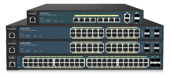
EWS Switch Series
IMPORTANT
To install this device please refer to the
Quick Installation Guide included in the product packaging.
2
Table of Contents |
|
Product Overview............................................................................................................................................... |
7 |
Introduction ............................................................................................................................................ |
8 |
Key Features........................................................................................................................................ |
9 |
System Requirements ....................................................................................................................... |
10 |
Package Contents.............................................................................................................................. |
10 |
Technical Specifications..................................................................................................................... |
11 |
Getting Started................................................................................................................................................. |
14 |
Installing the Switch .............................................................................................................................. |
15 |
Management Interface ..................................................................................................................... |
15 |
Connecting the Switch to a Network ................................................................................................ |
16 |
Software Features.......................................................................................................................................... |
18 |
Using the Switch.................................................................................................................................... |
19 |
Wireless Controller Features................................................................................................................. |
20 |
Managing EWS Access Points............................................................................................................ |
20 |
Device Management ......................................................................................................................... |
22 |
Summary ....................................................................................................................................... |
22 |
Access Points................................................................................................................................. |
24 |
Access Point Settings..................................................................................................................... |
29 |
AP Groups...................................................................................................................................... |
42 |
Access Control............................................................................................................................... |
44 |
Wireless Services........................................................................................................................... |
46 |
Monitor ............................................................................................................................................. |
47 |
Active Clients................................................................................................................................. |
47 |
Rogue AP Detection ...................................................................................................................... |
49 |
System Log .................................................................................................................................... |
51 |
Email Alert..................................................................................................................................... |
56 |
Visualization ...................................................................................................................................... |
60 |
Topology View............................................................................................................................... |
60 |
Map View ...................................................................................................................................... |
63 |
Floor View ..................................................................................................................................... |
65 |
Statistics ............................................................................................................................................ |
70 |
Access Points................................................................................................................................. |
70 |
3
Wireless Clients............................................................................................................................. |
71 |
Real Time Throughput................................................................................................................... |
72 |
Hotspot Services ............................................................................................................................... |
73 |
Captive Portal................................................................................................................................ |
73 |
Guest Account............................................................................................................................... |
75 |
Maintenance ..................................................................................................................................... |
76 |
Schedule Tasks .............................................................................................................................. |
76 |
Troubleshooting ............................................................................................................................ |
77 |
Bulk Upgrade................................................................................................................................. |
78 |
One-Click Update .......................................................................................................................... |
79 |
SSL Certificate................................................................................................................................ |
82 |
Check Codes.................................................................................................................................. |
84 |
Migration to ezMaster .................................................................................................................. |
85 |
Ethernet Switch Features...................................................................................................................... |
86 |
System............................................................................................................................................... |
86 |
Summary ....................................................................................................................................... |
86 |
IP Settings...................................................................................................................................... |
87 |
System Time .................................................................................................................................. |
90 |
Port Settings.................................................................................................................................. |
92 |
PoE ................................................................................................................................................ |
94 |
EEE................................................................................................................................................. |
97 |
L2 Feature.......................................................................................................................................... |
98 |
Link Aggregation............................................................................................................................ |
98 |
STP............................................................................................................................................... |
105 |
MAC Address Table ..................................................................................................................... |
116 |
LLDP............................................................................................................................................. |
118 |
IGMP Snooping ........................................................................................................................... |
122 |
MLD Snooping............................................................................................................................. |
128 |
Jumbo Frame............................................................................................................................... |
131 |
VLAN................................................................................................................................................ |
132 |
802.1Q......................................................................................................................................... |
133 |
PVID............................................................................................................................................. |
134 |
Management VLAN ..................................................................................................................... |
136 |
Voice VLAN.................................................................................................................................. |
137 |
4
Management................................................................................................................................... |
140 |
System Information..................................................................................................................... |
140 |
User Management ...................................................................................................................... |
141 |
Dual Image .................................................................................................................................. |
142 |
SNMP........................................................................................................................................... |
143 |
ACL .................................................................................................................................................. |
152 |
MAC ACL...................................................................................................................................... |
153 |
MAC ACE ..................................................................................................................................... |
154 |
IPv4 ACL....................................................................................................................................... |
156 |
IPv4 ACE ...................................................................................................................................... |
157 |
IPv6 ACL....................................................................................................................................... |
159 |
IPv6 ACE ...................................................................................................................................... |
160 |
ACL Binding ................................................................................................................................. |
162 |
QoS.................................................................................................................................................. |
163 |
Global Settings ............................................................................................................................ |
164 |
CoS Mapping ............................................................................................................................... |
165 |
DSCP Mapping............................................................................................................................. |
166 |
Port Settings................................................................................................................................ |
167 |
Storm Control.............................................................................................................................. |
169 |
Security ........................................................................................................................................... |
171 |
802.1x.......................................................................................................................................... |
171 |
RADIUS Server............................................................................................................................. |
175 |
Access.......................................................................................................................................... |
176 |
Port Security................................................................................................................................ |
180 |
Port Isolation............................................................................................................................... |
181 |
DoS .............................................................................................................................................. |
182 |
Monitoring ...................................................................................................................................... |
184 |
Port Statistics............................................................................................................................... |
184 |
RMON.......................................................................................................................................... |
185 |
Log............................................................................................................................................... |
190 |
Diagnostics ...................................................................................................................................... |
195 |
Cable Diagnostics ........................................................................................................................ |
195 |
Ping Test ...................................................................................................................................... |
196 |
IPv6 Ping Test .............................................................................................................................. |
197 |
5
Trace Route ................................................................................................................................. |
198 |
Maintenance ................................................................................................................................... |
199 |
Configuration Manager............................................................................................................... |
199 |
Firmware Upgrade ...................................................................................................................... |
200 |
Appendix .......................................................................................................................................................... |
201 |
Appendix A - Federal Communication Commission Interference Statement ..................................... |
202 |
Appendix B - IC Interference Statement ............................................................................................. |
203 |
Appendix C - CE Interference Statement ............................................................................................ |
204 |
6

Chapter 1
Product Overview
7
Introduction
The EnGenius EWS Series of Wireless Management Switches is an affordable centralized wired/wireless management system developed specifically for entry-level small-to-medium businesses. This powerful device can be easily deployed and operated by non-tech experts and installed effortless and quickly. Any organization with limited IT engineer and budget can create a stable and secure wireless network in no time. The system integrates seamlessly with existing routers, switches, firewalls, authentication servers and other network devices, and can be placed within any network, configured to act as a both a Wireless Controller as well as a Layer 2 Gigabit switch, providing robust and centralized management of the whole network through one powerful system. With no additional costs or license purchasing necessary, network administrators can manage and monitor both wired and wireless nodes through a single web interface.
The system can automatically discover any supported EnGenius EWS Series Access Points connected to the network with a simple click of a mouse, self-configure and become instantly manageable. Simply log into the device via any standard web browser and assign APs into cluster groups. Wireless radio, wireless security and other wireless related configurations can all be easily applied to multiple APs simultaneously, eliminating the time consuming process of configuring each and every Wireless Access Points individually.
The user friendly GUI provides instant access to a variety of client and network information including Managed AP List, Auto Discovered AP List, Cluster Grouping List, and Client List with complete MAC/IP Address, Incoming/Outgoing Traffic, Wireless Output Power and other relevant information. Statistics of AP and client traffics are automatically generated into easy-to-understand graphs, providing a visual representation of the network traffic.
Not to forget the Topology View feature that allows administrators to quickly see the whole wired/wireless network topology at real-time for easier planning, troubleshooting and monitoring, as well as Floor Plan View and Map View which allows for quickly locating deployed APs, a helpful feature for large scale AP deployment and multi-site management. There's also an Intelligent Diagnostics feature for administrators to check the status of Wireless APs and provide easy troubleshooting for offline units and even capable of rebooting APs remotely.
8
Key Features
>10/100/1000 Mbps Gigabit Ethernet Ports
>Dedicated SFP slots for longer connectivity via fiber uplinks and for uplink redundancy and failover
>IGMP and MLD snooping provides advanced multicast filtering
>IEEE802.3ad Link Aggregation
>STP/RSTP/MSTP
>Access Control List/ Port Security
>IEEE802.1X and RADIUS Authentication
>RMON
>SNMP v1/v2c/v3
>Voice VLAN for fast and reliable deployment of VoIP
>Energy Efficient Ethernet (IEEE802.3az) support for better energy saving when more EEE-compliant end devices are available in the market
>Advanced QoS with IPv4/IPv6 ingress traffic filtering (ACLs) and prioritization
>Easy to manage via Web-Based Management GUI for switch deployment
>Standard-based technology, ensuring interoperability with any standard-based devices in the existing network
>Dual firmware images, improving reliability and uptime for your network
9
System Requirements
The following are the minimum system requirements in order configure the device:
>Computer with an Ethernet interface or wireless network capability
>Windows OS (XP, Vista, 7, 8), Mac OS, or Linux-based operating systems
>Web-Browsing Application (i.e. Internet Explorer, Firefox, Chrome, Safari, or another similar browser application)
Package Contents
The package contains the following items (all items must be in package to issue a refund):
EWS1200D-10T, EWS2910P
>EnGenius Switch
>Power Adapter
>Wall-mount Kit
>Quick Installation Guide
EWS1200-28T/52T, EWS5912FP, EWS7928P/FP, EWS7952FP
>EnGenius Switch
>Power Cord
>Rack-mount Kit
>Quick Installation Guide
10
Technical Specifications
General
|
EWS1200D-10T |
EWS1200-28T |
EWS1200-52T |
10/100/1000Mbps Ports |
8 |
24 |
48 |
100/1000Mbps SFP Slots |
2 |
4 |
4 |
RJ45 Console Ports |
- |
1 |
1 |
Forwarding Mode |
|
Store-and-Forward |
|
SDRAM |
256 MB |
256 MB |
256 MB |
Flash Memory |
32 MB |
32 MB |
32 MB |
Packet Buffer Memory |
512 KB |
512 KB |
1.5 MB |
|
EWS2910P |
EWS5912FP |
EWS7928P |
EWS7928FP |
EWS7952FP |
10/100/1000Mbps Ports |
8 |
10 |
24 |
24 |
48 |
100/1000Mbps SFP Slots |
2 |
2 |
4 |
4 |
4 |
RJ45 Console Ports |
- |
1 |
1 |
1 |
1 |
PoE Standard |
IEEE 802.3 af |
|
IEEE 802.3 af/at |
|
|
PoE Capable Ports |
Port 1-8 |
Port 1-8 |
Port 1-24 |
Port 1-24 |
Port 1-48 |
Total PoE Power Budget |
55W |
130W |
185W |
370W |
740W |
Forwarding Mode |
|
Store-and-Forward |
|
|
|
SDRAM |
256 MB |
256 MB |
256 MB |
256 MB |
256 MB |
Flash Memory |
32 MB |
32 MB |
32 MB |
32 MB |
32 MB |
Packet Buffer Memory |
512 KB |
512 KB |
512 KB |
512 KB |
1.5 MB |
11
Software Features
Wireless Management Features
Access Point Auto Discovery and Provisioning Access Point Auto IP Assignment
Access Point Group Management Visual Topology View
Floor Plan View Map View
Access Point Status Monitoring Wireless Client Monitoring Wireless Traffic & Usage Statistics Real-time Throughput Monitoring Bulk Firmware Upgrade Capability Remote Access Point Rebooting Fast Roaming
Band Steering
Traffic Shaping Intelligent Diagnostics
Access Point Device Name Editing Access Point Radio Settings
RSSI Threshold
Access Point Client Limiting
Wireless Security (WEP, WPA/WPA2 Enterprise, WPA/WPA2 PSK)
VLANs for Access PointMultiple SSIDs Guest Network
Secure Control Messaging (SSL Certificate) Local MAC Address Database
Remote MAC Address Database (RADIUS) Configuration Import / Export
L2 Features
802.3ad Link Aggregation
-Maximum of 8 groups/8 ports per group Port Mirroring
-One-to-One
-Many-to-One
Spanning Tree Protocol
-802.1D Spanning Tree Protocol (STP)
-802.1w Rapid Spanning Tree Protocol (RSTP)
-802.1s Multiple Spanning Tree Protocol (MSTP) MAC Address Table
-8K entries
Static MAC Address
- 256 entries
802.1ab Link Layer Discovery Protocol IGMP Snooping
-IGMP v1/v2/v3 Snooping
-Supports 256 IGMP groups
-IGMP per VLAN
-IGMP Snooping Querier
-IGMP Snooping Fast Leave MLD Snooping
-MDL Snooping v1/v2
-Supports 256 MLD groups
-IGMP per VLAN
Jumbo Frame
- Up to 9216 bytes 802.3x Flow Control
802.3az Energy Efficient Ethernet
VLAN
802.1Q support VLAN Group
- Max 4094 static VLAN groups Voice VLAN
QoS
802.1p Quality of Service
-8 queues per port Queue Handling
-Strict
-Weighted Round Robin (WRR) QoS based on:
-802.1p Priority
-DSCP
Bandwidth Control
- Port-based (Ingress/Egress, 64 Kbps~1000
Mbps)
Broadcast/Unknown Multicast/ Unknown Unicast
Storm Control
Access Control List (ACL)
Layer 2/3
-Support maximum 32 entries (ACL)
-Support maximum 256 entries (ACE) ACL based on:
-MAC address
-VLAN ID
12
- 802.1p priority |
RFC1757 |
- Ethertype |
RFC2674 |
- IP address |
RFC 2863 |
- Protocol type |
|
- DSCP |
Environment Specifications |
|
Operating Temperature |
Security |
0 to 40°C (EWS1200D-10T, EWS2910P) |
802.1X |
0 to 50°C (EWS1200-28T/52T, EWS5912FP, |
- Guest VLAN |
EWS7228P/FP, EWS7952FP) |
- Port-based Access Control |
|
Supports RADIUS Authentication |
Storage Temperature |
Port Security |
-40°C to 70°C |
- up to 256 MAC Addresses per port |
|
Port Isolation |
Humidity (Non-condensing) |
DoS Attack Prevention |
5% - 95% |
BPDU Attack Prevention |
|
|
Physical Specifications |
Monitoring |
Dimensions (W x D x H) |
Port Statistics |
EWS1200D-10T, EWS2910P: 240x105x27mm |
System Log |
EWS5912FP: 330x230x44mm |
RMON |
EWS1200-28T/52T, EWS7228P: 440x260x44mm |
|
EWS7928FP: 440x310x44mm |
Management |
EWS7952FP: 440x410x44mm |
Web Graphical User Interface (GUI) |
|
Command Line Interface (CLI) |
|
BootP/DHCP Client/DHCPv6 Client |
|
SSH Server |
|
Telnet Server |
|
TFTP Client |
|
HTTPS |
|
SNMP |
|
- Supports v1/v2c/v3 |
|
SNMP Trap |
|
SNTP |
|
Configuration restore/backup |
|
Dual Images |
|
Diagnostic |
|
Cable Diagnostic |
|
Ping Test |
|
Trace Route |
|
MIB/RFC Standards |
|
RFC1213 |
|
RFC1493 |
|
13

Chapter 2
Getting Started
14
Installing the Switch
This section will guide you through the installation process.
Management Interface
The Switch features an embedded Web interface for the monitoring and management of your device.
Management Interface Default Values
IP Address: 192.168.0.239
Username: admin
Password: password
15
Connecting the Switch to a Network
Discovery in a Network with a DHCP server
Use the procedure below to setup the Switch within a network that uses DHCP.
1.Connect the supplied Power Cord to the Switch and plug the other end into an electrical outlet. Verify the power LED indicator is lit on the Switch.
2.Wait for the Switch to complete booting up. It might take a minute for the Switch to completely boot up.
3.Connect one end of a Category 5/6 Ethernet cable into the Gigabit (10/100/1000Mpbs) Ethernet port on the Switch front panel and the other end to the Ethernet port on the computer. Verify that the LED on the Ethernet ports of the Switch are Green.
4.Once your computer is on, ensure that your TCP/IP is set to On or Enabled. Open Network Connections and then click Local Area Connection. Select Internet Protocol Version 4 (TCP/IPv4). If your computer is already on a network, ensure that you have set it to a Static IP Address on the Interface (Example: 192.168.0.10 and the Subnet mask address as 255.255.255.0).
5.Open a web browser on your computer. In the address bar of the web browser, enter 192.168.0.239 and press Enter.
6.A login screen will appear. By default, the username is admin and the password is password. Enter the current password of the Switch and then click Login. To make access to the web-based management interface more secure, it's highly recommended that you change the password to something more unique.
7.Click IP Settings under the System tab and select IPv4 or IPv6.
8.Click DHCP under Auto-Configuration.
9.Click Apply to save the settings.
10.Connect the Switch to your network (DHCP enabled).
11.On the DHCP server, find and write down the IP address allocated to the device. Use this IP address to access the management interface.
16
Discovery in a Network with a DHCP server
This section describes how to set up the Switch in a network without a DHCP server. If your network has no DHCP service, you must assign a static IP address to your Switch in order to log in to the web-based management interface.
1.Connect the supplied Power Cord to the Switch and plug the other end into an electrical outlet. Verify the Power LED indicator is lit on the Switch.
2.Wait for the Switch to complete booting up. It might take a minute or so for the Switch to completely boot up.
3.Connect one end of a Category 5/6 Ethernet cable into the Gigabit (10/100/1000Mbps) Ethernet port on the Switch front panel and the other end to Ethernet port on the computer. Verify that the LED on Ethernet ports of the Switch are Green.
4.Once your computer is on, ensure that your TCP/IP is set to On or Enabled. Open Network Connections and then click Local Area Connection. Select Internet Protocol Version 4 (TCP/IPv4).
5.If your computer is already on a network, ensure that you have set it to a Static IP Address on the Interface (Example: 192.168.0.239 and the Subnet mask address as 255.255.255.0).
6.Open a web browser on your computer. In the address bar of the web browser, enter 192.168.0.239 and press Enter.
7.A login screen will appear. By default, the username is admin and the password is password. Enter the current password of the Switch and then click Login. To make access to the web-based management interface more secure, it's highly recommended that you change the password to something more unique.
8.Click IP Settings under the System menu and select Static IP to configure the IP settings of the management interface.
9.Enter the IP address, Subnet mask, and Gateway.
10.Click Apply to update the system.
17
Chapter 3
Software Features
18

Using the Switch
Besides the functions of a Wireless Controller, the EWS Wireless Management Switch also possesses functions of a full-featured Layer 2 Ethernet Switch. Use the Controller / Switch tab on the upper left corner of the user interface to toggle between the Wireless Controller or Layer 2 Switch functions.
19

Wireless Controller Features
Managing EWS Access Points
1.Access Points in the network will be automatically discovered by the EWS and will be listed under the AP(s) Detected list in the Access Point menu.
2. Select the Access Point(s) you wish to manage and click Add.
3. You will be prompted to assign the IP Address under the IP Assignment screen.
20
Auto-Configuration |
DHCP: You can choose to auto assign IP address if there is a |
|
DHCP server in the network. |
|
Static: If you wish to manually assign the IP address, choose |
|
Static. Enter the IP address you wish to assign to the AP and fill |
|
in the subnet mask, default gateway and DNS server address. |
|
Keep AP’s Settings: Select this option for the AP to use its |
|
current network settings. |
|
|
IP Address |
Enter the IP address for the Access Point. |
|
|
Subnet Mask |
Enter the subnet mask for the Access Point. |
|
|
Default Gateway |
Enter the default gateway for the Access Point. |
|
|
Primary DNS Server |
Enter the primary DNS server name. |
|
|
Secondary DNS Server |
Enter the secondary DNS server name (if necessary). |
|
|
4.Click Apply and the Access Point(s) you’ve configured will be moved to the Managed list. Note that the status of the AP will change from Connecting to Provisioning to Online. Once the status turns
Online, your Access Point(s) have been successfully added to the Managed list.
Note: If the status shows Incompatible Version, please check and make sure that the firmware of the
Access Point and Switch are compatible.
21

Device Management
Summary
The Summary page shows general system information for the EWS Switch including the Controller Status, the software version, the maximum number of APs the system can manage, MAC Address, IP Address, serial number, and system uptime for the system.
22

Dashboard
The Dashboard on the upper right corner of the GUI shows the current status of EWS APs that has been
managed by the EWS Switch.
Managed |
This shows the number of APs currently managed by the EWS Switch. |
|
|
|
|
Active |
This shows the number of managed APs that currently have an active connection with the |
|
|
EWS Switch. |
|
|
|
|
Offline |
This shows the number of managed APs that currently do not have an active connection with |
|
|
the EWS Switch. |
|
|
|
|
Clients |
This shows the total number of wireless clients currently connected to all the managed APs. |
|
|
|
Controller State
Status: Select whether to Enable or Disable the Controller feature on the Switch.
ezMaster Address: If you have an ezMaster server running and wants to have ezMaster manage this EWS Switch directly, enter the IP Address/domain name of the ezMaster server.
Click Apply to save the changes to the system.
System Information
Controller Version: This is the software version of the device.
Max. Managed APs: The maximum number of APs the device is able to manage.
IP Address: Displays the IP address of the device.
Base MAC Address: Universally assigned network address.
Serial Number: Displays the serial number of the device.
System Uptime: Displays the number of days, hours, and minutes since the last system restart.
23

Access Points
This page displays the status of all EWS Access Points that your Controller is currently managing as well as all the EWS Access Points in the network that the Controller has discovered. Use this page to add EWS Access Points to your EWS Controller Access Point list.
The EWS Switch is able to manage supported EWS Series Access Points. For the discovery procedure to succeed, the EWS Switch and the EWS Access Point must be connected in the same network. The EWS Switch can discover supported EWS Access Points with any IP address and Subnet settings.
Managing Access Points
EWS Access Points can either be configured individually or configured as a group.
To manage an Access Point individually, click on the Device Name field of the Access Point you wish to configure and you will be directed to a screen where you can configure settings for the Access Point.
To manage Access Points as a group, go to Device Management > AP Clusters to create an AP group and add members into the group. Click on the Group field of the AP you wish to configure and you will be directed to a screen where you can configure settings for the AP Group.
Group settings can be overridden by individual AP settings. For example, if you want to set the transmit power to a lower setting for only a few specific APs, leave the Transmit Power at Auto in the Wireless
24

Radio Settings of the AP Group, then click on the Device Name field of the Access Point (which is already in a group) you wish to configure and you will be directed to a screen where you can configure override settings for the selected Access Point.
Refresh Countdown Timer
This is the time left before the page auto-refreshes. The countdown is from 15 seconds.
Dashboard
The Dashboard shows the current status of all the EWS APs that has been managed by the EWS Switch.
Managed |
This shows the number of APs in the managed AP database that are configured |
|
with the EWS Switch. |
|
|
Active |
This shows the number of managed APs that currently have an active connection |
|
with the EWS Switch. |
|
|
Offline |
This shows the number of managed APs that currently do not have an active |
|
connection with the EWS Switch. |
|
|
AP(s) Detected List
Reveals a list of all APs in the network that the EWS Switch automatically discovers. Mouse over the discovered Access Point to show general information such as the MAC address, IP address, model name and firmware version.
25

Remove AP
The Remove button removes selected Access Point(s) from list. Access Points removed will be automatically set to standalone mode with all settings restored to their factory default settings.
Reboot AP
The Reboot button will reboot the selected Access Point(s).
Search Bar
Use the Search Bar to search for Access Points managed by the EWS Switch using the following criteria: Status, model name, MAC Address, Device name, IP address, Firmware Version, Cluster.
Status
This indicates the current status of the managed Access Point.
Status |
Explanation |
|
|
Online |
AP is connected and managed by EWS Switch. |
|
|
Provisioning |
AP is currently in the process of connecting to the EWS Switch. |
|
|
Applying Change |
AP is currently applying system changes. |
|
|
Connecting |
AP is currently connecting to EWS Switch. |
|
|
Offline |
AP is currently offline. |
|
|
26
Resetting |
AP is resetting. |
|
|
Firmware |
AP is currently undergoing firmware upgrade process. |
Upgrading |
|
|
|
Invalid IP |
The subnet of managed AP’s IP address is not the same as the EWS Switch. Please |
|
remove AP and reconfigure AP to the correct setting. |
|
|
Incompatible |
AP firmware is not compatible with EWS Switch. |
Version |
|
|
|
Checking |
EWS Switch is checking the SSL Certificate of AP. |
Certificate |
|
|
|
Model Name
Shows the model name of the managed Access Point.
MAC Address
Shows the MAC address of the managed Access Point.
Device Name
Displays the device name of the managed Access Point.
When the AP is not a cluster member, click on this field and you’ll be redirected to the configuration page where you can edit settings such as device name, IP Address, Wireless Radio settings.
When the AP is a cluster member, click on this field to configure settings for individual Access Points by overriding the cluster settings.
IP Address
Shows the IP address of the managed Access Point.
27

Firmware Version
Shows the firmware version of the managed Access Point.
Last Update
Display the time the Access Point was last detected and the information was last updated.
Group
Displays the AP Group the Access Point is currently assigned to. Click on this field and you'll be redirected to the group configuration page.
Column Filter
Shows or hides fields in the Access Point list.
28

Access Point Settings
On this page, you can edit the AP's name and password, manually assign an IP address, or change the channel selection, transmit power and other wireless settings of a managed Access Point.
General Settings
Device Name: The device name of the Access Point. Users can enter a custom name for the Access Point
if they wish.
Administrator Username: Displays the current administrator login username for the Access Point. Enter a new Administrator username for the Access Point if you wish to change the username. The default username is: admin.
New Password: Enter a new password of between 1~12 alphanumeric characters.
Verify Password: Enter the password again for confirmation.
Auto Configuration: Select whether the device IP address will use the static IP address specified in the IP Address field or be obtained automatically when the device connects to a DHCP server.
IP Address: Enter the IP address for the Access Point.
Subnet Mask: Enter the Subnet Mask for the Access Point.
Default Gateway: Enter the default Gateway for the Access Point.
Primary/Secondary DNS Server: Enter the Primary/Secondary DNS server name.
29

Wireless Radio Settings
Country: Select a Country/Region to conform to local regulations. Different regions have different rules that govern which channels can be used for wireless communications.
Wireless Mode: Select from the drop-down menu to set the wireless mode for the Access Point. For 2.4GHz, the available options are 802.11b/g/n mixed, 802.11b, 802.11b/g mixed, 802.11g, and 802.11n. For 5GHz, the available options are 802.11a/n mixed, 802.11a, and 802.11n.
Channel HT Mode: Use the drop-down menu to select the Channel HT as 20MHz, 20/40MHz or 40MHz. A wider channel improves the performance, but some legacy devices operate only on either 20MHz or 40 MHz. This option is only available for 802.11n modes.
Extension Channel: Use the drop-down menu to set the Extension Channel as Upper or Lower channel. An extension channel is a secondary channel used to bond with the primary channel to increase this range to 40MHz allowing for greater bandwidth. This option is only available when Wireless Mode is 802.11n and Channel HT Mode is 20/40MHz or 40MHz.
Channel: Use the drop-down menu to select the wireless channel the radio will operate on. Optimizing channel assignments reduces channel interference and channel utilization for the network, thereby improving overall network performance and increasing the network's client capacity. The list of available channels that can be assigned to radios is determined based on which country the Access Points are deployed in.
30
 Loading...